

Page 1
Tel:
+44
(0)191 490 1547
Fax:
+44 (0)191 477 5371
Email:
northernsales@thorneandderrick.co.uk
Website: www.heattracing.co.uk
www.thorneanderrick.co.uk
D
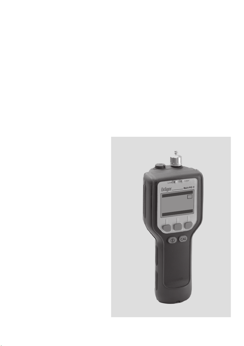
Dräger Multi-PID 2
Portable Photoionization Monitor
Instrument User manual
Software Version 3.nn
9/3/2
1.0
0.0
:
TEL
S
2.9
:
PEAK
view
T
IN
PPM
0.1
:
A
TW
0:05
nu
e
m
lear
c
9
0
:
0
1
6
00
ST–2425–2003_en.eps
Page 2

Contents
For Your Safety ...................................................................................................................................................... 5
Notices and Warnings ......................................................................................................................................... 7
FCC Warning ..................................................................................................................... 8
The Multi-PID 2 Intrinsic Safety (I/S) Notice ........................................................................ 8
ATEX Directive and EMC Directive ................................................................................... 11
WARNING ....................................................................................................................... 12
Introduction ......................................................................................................................................................... 15
About this Manual ............................................................................................................. 16
Warnings and Safety Practices ......................................................................................... 17
Approved Models of the Multi-PID 2 .................................................................................. 17
Excessive Heat and Cold .................................................................................................. 17
Intended Use .................................................................................................................... 18
Multi-PID 2 Overview ........................................................................................................ 18
General Operation ............................................................................................................ 20
Photoionization Detector ................................................................................................... 21
Unpacking Instrument ....................................................................................................... 23
Support Equipment and Consumables .............................................................................. 24
Using the Multi-PID 2 ........................................................................................................................................ 25
Battery Charging .............................................................................................................. 26
Display ............................................................................................................................. 29
Multi-PID 2 User Menu ...................................................................................................... 30
Keys ................................................................................................................................. 32
Beginning Operation ......................................................................................................... 33
Preparing for Field Operation ............................................................................................ 40
Connecting Accessories .................................................................................................................................. 43
Computer ......................................................................................................................... 44
Pre-filter Tube Holder ....................................................................................................... 45
Pre-filters and Sample Collection Tubes ............................................................................ 46
Sample Line ..................................................................................................................... 46
Wrist Strap ....................................................................................................................... 47
DC Power Cord ............................................................................................................... 47
Belt Clip Holster ............................................................................................................... 47
11.7 eV UV Lamp ............................................................................................................. 48
Off-Line Charger .............................................................................................................. 50
2
Page 3

Menu Functions .................................................................................................................................................. 53
User Interface – Basic Menu ............................................................................................. 54
Operation Modes .............................................................................................................. 54
Unit Setup Menu ............................................................................................................... 55
Memory slots Menu ........................................................................................................... 65
Data Log Options Menu .................................................................................................... 68
Clear values Menu ............................................................................................................. 70
Edit Alarms Menu .............................................................................................................. 70
Humidity Tube Menu ......................................................................................................... 70
Routine Maintenance ........................................................................................................................................ 71
Maintenance Intervals ........................................................................................................ 72
Calibration Technical Description ...................................................................................... 72
Calibration Introduction ..................................................................................................... 73
Calibration Using the Flow-Match Regulator ...................................................................... 76
Battery Charging ............................................................................................................... 78
Maintenance of the UV Lamp ............................................................................................. 80
Replacing the Sample Inlet Filter ....................................................................................... 84
Waste electrical and electronic equipment ......................................................................... 85
Troubleshooting .................................................................................................................................................. 87
General Information ........................................................................................................... 88
Troubleshooting ................................................................................................................ 89
General Questions ............................................................................................................ 91
Appendices .......................................................................................................................................................... 93
Specification ..................................................................................................................... 94
Installing Alternate AC Plug on the Battery Charger ........................................................... 96
Calibration Gas Supplier ................................................................................................... 96
Presets and Response Factors .......................................................................................... 97
Reference ....................................................................................................................... 103
3
Page 4

Figures
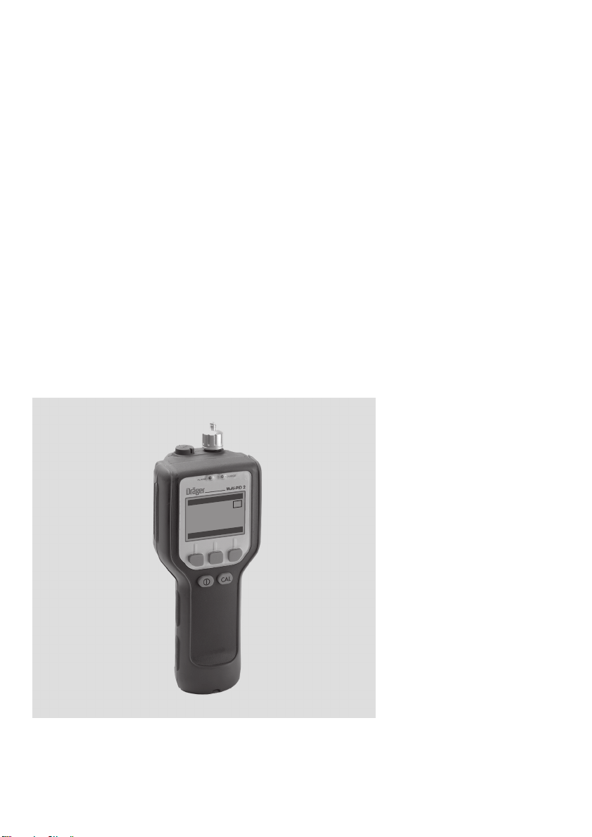
Figure 1 – Multi-PID 2 ......................................................................................................... 18
Figure 2 – Multi-PID 2 Block Diagram ................................................................................. 20
Figure 3 – Photoionization Detector .................................................................................... 22
Figure 4 – Battery Pack Removal and Replacement ............................................................ 27
Figure 5 – Multi-PID 2 Display ............................................................................................ 29
Figure 6 – User Menu, GAS mode ...................................................................................... 30
Figure 7 – User Menu, TVOC mode ................................................................................... 31
Figure 8 – GAS mode Display ............................................................................................ 33
Figure 9 – Logging Off Mode Display ................................................................................. 34
Figure 10 – TAG Mode Display ........................................................................................... 35
Figure 11 – Interval Mode Display ....................................................................................... 35
Figure 12 – Tube Holder ..................................................................................................... 45
Figure 13 – Dräger Pre-filter Tubes ..................................................................................... 46
Figure 14 – Unit Setup Map ................................................................................................ 56
Figure 15 – Intervall time adjustment ................................................................................... 61
Figure 16 – Setting the Time ............................................................................................... 62
............................................................................................................................................ 66
Figure 17 – Function Memory Slots Settings ....................................................................... 67
Figure 18 – Calibration with Flow-Math ............................................................................... 76
Figure 19 – Removing the UV Lamp .................................................................................... 81
Figure 20 – Replacing the Inlet Filter ................................................................................... 85
Tables
Table 1 – System Alerts ................................................................................................................................ 37
Table 2 – Check List for Field Items .......................................................................................................... 40
Table 3 – Additional Field Items .................................................................................................................. 40
Table 4 – Averaging Intervals and Period STEL, TWA, and REAL Operation .............................. 61
Table 5 – Response Factors ........................................................................................................................ 97
Table 6 – Library Entries ............................................................................................................................. 100
4
Page 5

5
For Your Safety
Strictly follow the Instructions for Use
Any use of this instrument requires a full understanding and strict
adherence to these instructions.
This instrument is only to be used for the purposes specified here
(see “Intended Use” on page 18).
Maintenance
The Multi-PID 2 must be inspected and serviced by trained service
personnel at regular intervals.
Repair of the Multi-PID 2 may only be carried out by trained service
personnel.
Only authentic Dräger Safety spare parts may be used for maintenance.
Observe chapter “Maintenance Intervals” on page 72..
We recommend that a service contract be obtained with the service
of Dräger Safety and that all repairs are also carried out by them.
Use in areas subject to explosion hazards
This instrument and its components have been tested and approved
according to the European Directives 94/9/ EC (ATEX Directive) and
2004/108/EC (The electromagnetic Compatibility Directive) and may
be used only under the conditions explicitly specified in the EC Declaration of Conformity, see page 11.
Modifications of components or the use of faulty or incomplete parts
is not permitted. When making repairs to equipment or components
of this type, the relevant national regulations must be adhered to.
For Your Safety
Page 6

6
For Your Safety
Copyright Information
This document contains proprietary information that is protected by
copyright. All rights are reserved. No part of this publication may be
reproduced in any form whatsoever or translated into any language
without the prior, written permission of Dräger Safety.
Trademarks
Registered names, trademarks, etc. used in this document, even
when not specifically marked as such, are protected by law.
Page 7

7
Notices and Warnings
Notices and Warnings
Page 8

8
Notices and Warnings
FCC Warning
This instrument has been tested and found to comply with the limits
for a Class B Digital Device, pursuant to Subpart B, Class B of Part
15 of the FCC rules. These limits are designed to provide reasonable
protection against harmful interference when the equipment is operated in a commercial environment. This equipment generates, uses
and can radiate radio frequency energy and if not installed and used
in accordance with the instruction manual, may cause harmful interference to radio communications. Operation of this equipment in a residential area is likely to cause harmful interference in which case the
user will be required to correct the interference at their expense.
The Multi-PID 2 Intrinsic Safety (I/S) Notice
The Multi-PID 2 is classified for use in class I, division 1, groups A, B,
C, D hazardous locations. T4 (135
The Multi-PID 2 has been listed by MET Laboratories, Inc., to comply
with Underwriters Laboratories
cally Safe Apparatus and Associated Apparatus for use in Class I,
Division 1, Groups A, B, C, D Hazardous (Classified) Locations, Sixth
Edition when powered by 83 23 622 or 83 17 670 Battery Pack.
The Multi-PID 2 is not intended to detect combustible levels of gases.
The Multi-PID 2 is classified for use in atmospheres containig combustible levels of gases.
®
Inc. UL
o
C) rating.
®
913 Standard for Intrinsi-
Page 9

9
These optional accessories may be used with the Multi-PID 2 in a
hazardous location:
Name and Discription Part No.
Calibration Regulator 68 10 688
Wrist Strap 83 17 673
Belt-Clip Holster 83 17 677
Carrying Case 83 17 664
User’s Reference Card 90 23 770
Long Sample Probe 64 05 411
Short Sample Probe 64 05 412
Tube Holder 83 19 093
Dräger Tube, Carbon filter CH 24 101
Sampling Tube (Activated Charcoal, Type BIA) 67 33 011
PID Pre-Filter Tube Benzene 81 03 511
Dräger Tube, Humidity filter 81 03 531
NiMH battery pack 83 23 622
Ni/Cd battery pack 83 17 670
Notices and Warnings
WARNING:
Do not use any other accessories with the Multi-PID 2 in a hazardous location, danger of an explosion!
Substitution of components may affect safety rating.
CAUTION:
To reduce the risk of fire or injury to persons, read and follow
these instructions:
1.
All calibration, maintenance and servicing of this device,
including battery charging, must be performed in a safe
area away from hazardous locations. Disconnect all power
before servicing.
2.
There are no operator replaceable parts inside the
Multi-PID 2 except the battery pack, UV lamp and sample
inlet filter.
3.
There are no operator serviceable par ts inside the
Multi-PID 2.
Page 10

Notices and Warnings
WARNING:
1.
For replacement battery pack use only Par t No. 83 23 622
or 83 17 670.
2.
Do not dispose of the battery pack in a fire. The cells may
explode. The battery pack must be disposed of properly.
Check with local codes for possible special disposal instructions.
3.
Do not open or mutilate the battery pack. If the Multi-PID 2 is
used in a manner not specified, the protection provided by
the Multi-PID 2 may be impaired.
4.
Exercise care in handling battery packs in order not to short
the terminals with conducting materials such as rings, bracelets and keys. The battery or conductor may overheat and
cause burns.
5.
Do not defeat proper polarity orientation between the battery pack and battery charger.
6.
Charging the battery is only to be done in a nonhazardous
area.
7.
Charge the battery pack using the AC adapter provided with
or identified for use with this product only in accordance
with the instructions and limitations specified in this manual.
For AC adapter use only Part No. 64 05 428 (115 Volt AC),
Part No. 83 17 661 (220 Volt AC). When using the AC adapter do not block access to AC outlet in use with adapter. AC
adapter is not to be used in a hazardous area.
10
Page 11
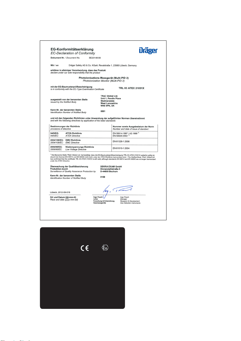
ATEX Directive and EMC Directive
11
Notices and Warnings
Model: Multi-PID 2 Photoionization Monitor
Certified Intrinsically Safe/Securite Intrinséque.
Class I, Division 1, Groups A B C and D.
Maximum surface temperature 135°C T4.
Model: Multi-PID 2
TRL: 03ATEX21031X
EEx ib IIC T4 (Ta = 0°C to +40°C)
Dräger Safety, D23560 Lübeck, Germany
WARNING - Substitution of components may impair
intrinsic safe. Avertissement - La substitution de
composants peut compromettre la securite intrinsique.
To prevent ignition of flammable or combustible
atmospheres, disconnect power before servicing.
CAUTION - To reduce the risk of explosion, only use
AC Adapter and Serial Port or recharge the batteries
outside of the hazardous location. Avertissement - Afin
de prevenir l’inflammation d’atmosphères dangereuses,
ne charger les batteries que dans des emplacements
designes non dangereux. Use only Dräger battery pack
Part No. 8317670 or 8323622 .
0158
II 2G
02423957_02.eps
Page 12

12
Notices and Warnings
WARNING
1. All calibration, maintenance and servicing of this device, including
battery charging, must be performed in a safe area away from hazardous locations.
2. Disconnect all power before servicing.
3. Do not open UV Lamp Cap when unit is energized.
4. Only use the AC Adapter in a safe area away from hazardous locations
5. Only use the Serial Port in a safe area away from hazardous locations.
CAUTION
To reduce the risk of fire or injury to persons, read and follow these
instructions:
1. There are no operator replaceable parts inside the Multi-PID 2 except the battery pack, UV lamp and sample inlet filter.
2. For replacement battery pack use only Dräger Part No. 83 23 622
or 83 17 670.
3. There are no operator serviceable parts inside the Multi-PID 2.
4. Do not dispose of the battery pack in a fire. The cells may explode.
The battery pack must be disposed of properly. Check with local codes for possible special disposal instructions.
5. Do not open or mutilate the battery pack. If the Multi-PID 2 is used
in a manner not specified, the protection provided by the
Multi-PID 2 may be impaired.
6. Exercise care in handling battery packs in order not to short the terminals with conducting materials such as rings, bracelets and keys.
The battery or conductor may overheat and cause burns.
7. Do not defeat proper polarity orientation between the battery pack
and battery charger.
8. Charge the battery pack using the AC adapter provided with or identified for use with this product only in accordance with the instructions and limitations specified in this manual. For AC adapter use
only Part No. 64 05 428 (115 Volt AC), Part No. 83 17 661
(220 Volt AC)). When using the AC adapter do not block access to
AC outlet in use with adapter. AC adapter is not to be used in a hazardous area.
Page 13

13
These optional accessories may be used with the Multi-PID 2 in a
hazardous location:
Name and Discription Part No.
Calibration Regulator 68 10 688
Wrist Strap 83 17 673
Belt-Clip Holster 83 17 677
Carrying Case 83 17 664
User’s Reference Card 90 23 770
Long Sample Probe 64 05 411
Short Sample Probe 64 05 412
Tube Holder 83 19 093
Dräger Tube, Carbon filter CH 24 101
Sampling Tube (Activated Charcoal, Type
BIA)
PID Pre-Filter Tube Benzene 81 03 511
Dräger Tube, Humidity filter 81 03 531
NiMH battery pack 83 23 622
Ni/Cd battery pack 83 17 670
67 33 011
Notices and Warnings
Do not use any other accessories with the Multi-PID 2 in a hazardous
location.
Page 14

Notices and Warnings
14
Page 15

Introduction
15
Introduction
Page 16

Introduction
About this Manual
This manual provides detailed instructions for setup, operation and
maintenance of the Multi-PID 2 Portable Photoionization Monitor.
Before unpacking the instrument, please read Warnings and Safety
Practices. This section describes possible hazards that might injure
the user, damage the instrument or compromise its operation. Some
general safety information is also provided.
To help you learn to use the Multi-PID 2 quickly, this manual is organized by tasks beginning with:
— Using the Multi-PID 2 in “Using the Multi-PID 2” on page 25..
— Accessories are covered in “Connecting Accessories” on
page 43..
— Routine maintenance is covered in “Routine Maintenance” on
page 71..
— Troubleshooting techniques are covered in “Troubleshooting” on
page 87..
The Multi-PID 2 manual uses a few conventions for key names on the
keypad and for text that is shown on the display.
16
» Display Text «
Texts shown on the Multi-PID 2 display are written with quotation
marks, e.g.
The names of soft keys are also written with quotation marks, e.g.
" select " .
In the text you will find various warnings and notes.
NOTE:
A note indicates significant information.
» Enter current time « .
WARNING:
A warning indicates an operation that could cause
personal injury if precautions are not followed.
CAUTION:
A caution indicates an operation that could cause
instrument damage if precautions are not followed.
Page 17
Warnings and Safety Practices
Please read the Notices and Warnings section of this user’s manual
before operating the Multi-PID 2.
Approved Models of the Multi-PID 2
This manual provides operational information for all models of the
Multi-PID 2. The Multi-PID 2 is intrinsically safe and approved for use
in hazardous locations. Refer to the Notices and Warnings section of
this manual for details of each approval.
Throughout the manual, notes are provided to inform you of any limitations of usage for the Multi-PID 2 models.
WARNING:
If the Multi-PID 2 you are using is not specifically
identified as intrinsically safe with a label on the
Multi-PID 2, do not use it in a location where
flammable concentrations of gases and vapors may
exist.
17
Introduction
Excessive Heat and Cold
WARNING:
Do not expose the instrument to intense sunlight for
prolonged periods.
Exposure to excessive heat or cold may result in
erroneous readings.
Page 18
Introduction
Intended Use
The Multi-PID 2 measures the concentration of airborne gases and
vapors that can be ionized by a photoionization detector.
The Multi-PID 2 automatically displays and can record these concentrations.
In the TVOC mode the Multi-PID 2 does not distinguish between
individual compounds.
The reading displayed represents the total concentration of all photoionizable chemicals present in the sample. The Multi-PID 2 is factory-set to display concentration in units of ppm.
Benzene is selectively measured in GAS mode.
This measurement requires the use of the PID pre-filter tube benzene.
The pre-filter tube adsorbs all substances with the exception of benzene. Only benzene passes into the detector.
Multi-PID 2 Overview
18
Figure 1 – Multi-PID 2
9
ST
P
v
/2006
/3
L
E
K
EA
w
ie
10
1.0
: 0.0
: 2.9
clear m
09
:
T
IN
PPM
.1
: 0
A
TW
5
0
0:
u
en
00523958_01_en.eps
Page 19

The Multi-PID 2 operates automatically. The Multi-PID 2 display
updates itself once per second. You can read concentrations directly
from the display.
The Multi-PID 2 will perform short-term exposure limit (STEL), timeweighted average (TWA) and REAL calculations when it is in INTERVAL mode. You can view any of these results in INTERVAL mode.
The Multi-PID 2 has two datalogging options, TAG and INTERVAL
mode. TAG mode allows the user to manually tag and store readings
during a walkthrough. Interval mode allows the user to datalog at selectable intervals of 3 seconds to 900 seconds.
In INTERVAL mode, the STEL, REAL and TWA are calculated. If you
select INTERVAL mode, these values are automatically recorded in
the Multi-PID 2’s memory. The Multi-PID 2 can log up to 12,000 entries.
In TAG mode operation, the Multi-PID 2 prompts you to locate a site
and then to record a background and sample readings for the site.
You can record up to 12,000 manual entries. There is no averaging of
data in TAG mode. Tags are set via the PC using the Dräger GasVision software.
19
Introduction
Recorded data can be reviewed on the display or downloaded to a
computer. Data are recorded by date and time.
The Multi-PID 2 has 5 keys for instrument operation. The keys are
used to set up and calibrate the Multi-PID 2. All information entered
with the keys and stored in the Multi-PID 2’s memory is retained when
the instrument is switched off. The clock and calendar continue to
operate and do not need to be reset when the Multi-PID 2 is turned
on.
Page 20

Introduction
General Operation
The Multi-PID 2 is a microprocessor-controlled air monitor for measuring the presence of photoionizable compounds in air at parts-per-million levels. The block diagram in Figure 2 shows the main
components of the Multi-PID 2.
Sample OutSample In
20
Inlet
Filter
Power
Supply
Photoionization
Detector
Microprocessor
Pump
Display and
I/O Connector
Keypad
Electrocal Connections
Figure 2 – Multi-PID 2 Block Diagram
The microprocessor controls the components of the instrument and
interprets and records the signal generated by the photoionization
detector (PID). Recorded data and setup information entered into the
microprocessor’s memory are retained when the Multi-PID 2 is turned
off.
A pump continuously pulls the air under test through the Multi-PID 2’s
PID. The Multi-PID 2 converts the concentration of photoionizable
compounds in the sample into an electrical signal. The microprocessor subtracts any background from the signal and divides this signal
by a sensitivity obtained by calibrating with a standard gas of known
concentration. This concentration appears on the Multi-PID 2’s display and, depending on the values entered through the Multi-PID 2’s
keypad, an alarm status may be displayed and an audio signal may be
heard.
Gas Connections
00623958_01_en.eps
The Multi-PID 2 can detect thousands of different types of airborne
gases and vapors and its response depends on the characteristics as
well as the concentration of each compound.
The Multi-PID 2 does not distinguish one type of compound from
another, but displays a number indicating the total concentration
of all photoionizable compounds in the sample.
Page 21

A standard of isobutylene at a known concentration may be used for
setting the sensitivity. If the Multi-PID 2 is calibrated with isobutylene,
it displays concentrations in units equivalent to ppm of isobutylene. If
isobutylene were the only photoionizable chemical in the sample,
then the Multi-PID 2 would display its concentration directly.
The Multi-PID 2 responds more or less readily to other chemicals than
it does to isobutylene. Because it has a medium sensitivity to isobutylene, this gas has been chosen as a reliable means of reporting an
average concentration of total ionizable compounds present.
Gases other than isobutylene can be used to calibrate the MultiPID 2. However, all response factors are based on an isobutylene
calibration.
21
Introduction
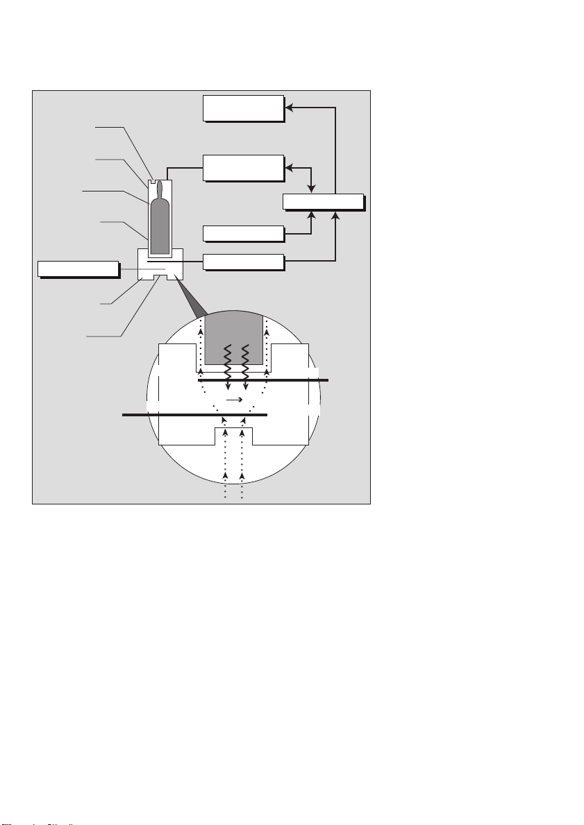
Photoionization Detector
The photoionization detector (PID) is shown in Figure 3. The PID measures the concentration of photoionizable chemicals in the gas
stream from the sample inlet and produces an electrical signal for the
microprocessor.
A UV lamp generates photons which ionize specific molecules in the
gas stream. The permanent air gases (argon, carbon dioxide, nitrogen, oxygen, water vapor, etc.) require a relatively high energy for ionization, and are not ionized by the UV photons. Many of the
compounds considered pollutants, including most hydrocarbons, are
ionized.
The gas stream is directed into the PID through a small port at the
center of the UV lamp window and through a series of larger ports
around the perimeter of the lamp window. This arrangement permits a
high sample flow rate and short response time.
Page 22
Introduction
Sample Out
Lamp Power
Supply
22
Lampholder
UV Lamp
High Voltage
Excitation
+125 Volt
Detector Cell
Sample In
UV Light
Counter Electrode
Figure 3 – Photoionization Detector
Lamp Driver
Circuit
Light Sensor
Amplifier
UV Lamp
M + hn M+ + e
M
M
M
Sample
M
Microprocessor
Measuring Electrode
–
Ionized Molecule
The ionized molecules in the detector cell are subjected to the
electric field between the electrodes. This generates a current which
is proportional to the concentration of the ionized molecules in the
detector cell. An amplifier converts the current to a voltage which is
then fed to the microprocessor.
00723958_01_en.eps
The UV lamp is operated by a high voltage lamp driver circuit which
injects its energy through plates in the lamp holder.
The lamp driver power supply is controlled by the microprocessor
based on a feedback signal from a light sensor on the driver circuit
board.
Page 23

Unpacking Instrument
Remove the Multi-PID 2 from its shipping box. The following accessories are included with the Multi-PID 2:
1. Sample Probe
2. Instrument Manual
3. Multi-Tool
4. AC Adapter or AC Adapter with AC Line Cord
5. Wrist Strap
6. Replacement Sample Inlet Filters (25 pieces)
7. Reference Card
Ensure that all of these accessories have been included with the
instrument. If any items are missing or damaged, contact Dräger
Safety immediately.
Introduction
23
Page 24

Introduction
Support Equipment and Consumables
Calibration
For normal operation these items are required:
1. Calibration Gas Regulator (Part No. 68 10 688).
2. Calibration gas containing 100 ppm isobutylene (Part No.
68 10 687). Other concentrations of the calibration gas may be required. This will depend on your application.
3. Zero air (clean dry air without any organic impurities)
There are several alternatives for clean or zero air calibration: you
can use a bottle of clean air (certified as having not more than
0.1 ppm total hydrocarbons) connected directly to the instrument;
the clean air can be transferred to a Tedlar bag which can then be
connected to the instrument; clean, ambient air without detectable
contamination; or, ambient air run first through the charcoal filter
(Part No. CH 24 101).
4. If compound threshold limit values (TLVs) are exceeded, you
should use a gas bag for sampling and calibration.
To determine the TLV of the compounds contained in the calibration gas, refer to the Material Safety Data Sheet (MSDS) supplied
with your calibration gas cylinder.
24
Field Operation
For field operation, the Multi-PID 2 Field Kit (Part No. 83 17 663) is
available.
The field kit includes a cable kit, a carrying case and a calibration
regulator, and a spare battery pack.
Refer to the check list in on page 41 to ensure you have all the necessary accessories and equipment before beginning field operation.
Computer
The Multi-PID 2 may also be connected to a computer. The computer
must be a Windows
Use the cable kit (Part No. 83 17 667) to connect the Multi-PID 2 to
the computer.
Stored datas are evaluated using the Dräger GasVision software
(Part No. 83 14 034).
TM
-based PC.
WARNING:
The Multi-PID 2 is not classified for use in hazardous locations when connected to a computer,
danger of an explosion!.
Page 25

Using the Multi-PID 2
Using the Multi-PID 2
25
Page 26

Using the Multi-PID 2
Battery Charging
Before beginning operation of the Multi-PID 2, the battery pack must
be charged.
You can also remove the battery pack and replace it with a fully charged spare battery pack (Part No. 83 23 622 or 83 17 670).
NOTE:
You must use the 220 V battery charger (Part No. 83 17 661) in
order to comply with the requirements of the applicable Council
Directives.
Removing and Replacing the Battery Pack
WARNING:
Do not remove or recharge the battery pack in a
hazardous location. danger of an explosion!
To remove the battery pack:
1. If the Multi-PID 2 has been turned on, turn it off by pressing the
ON/OFF key for five seconds and then releasing it.
NOTE:
If you do not turn the Multi-PID 2 off before removing the battery
pack, you will reset the instrument and you will lose all logged
data and setup parameters.
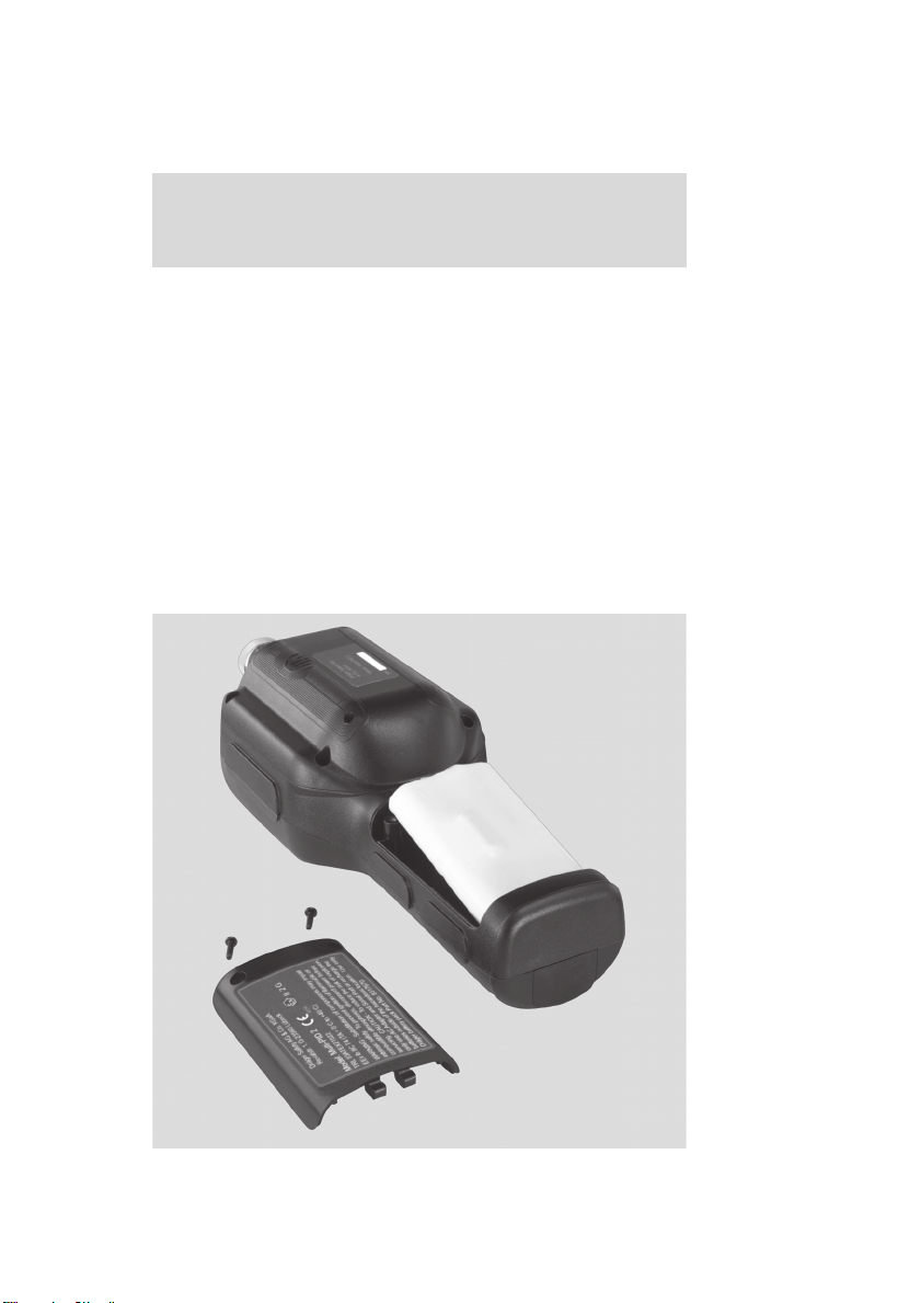
2. Locate the battery hatch on the back of the instrument.
See Figure 4.
3. Loosen the two Phillips screws in the top of the battery hatch.
4. The battery hatch can now be removed.
5. Lift the battery pack out of the case and carefully disconnect the
battery pack connector from the Multi-PID 2.
6. Attach the connector from the charged battery pack to the
Multi-PID 2.
NOTE:
The connector is polarized. It will only fit one way. Do not force
the connection.
7. Place the battery pack in the Multi-PID 2 case. Ensure the battery
wires are not pinched or strained.
8. Ensure the wrist strap ring is in proper position. This ring holds the
wrist strap in place.
9. Replace the battery hatch and then replace the two screws. Do not
overtighten the screws as you will damage the case.
26
Page 27
Charging the Battery Pack
NOTE:
Only use the AC adapter specified for use with the Multi-PID 2.
Using another AC adapter will result in damage to the battery
pack, the Multi-PID 2 or the adapter itself.
To charge the battery pack:
1. Plug the AC adapter into the jack located on the bottom of the
Multi-PID 2.
2. Plug the AC adapter into an AC outlet. If you are using the European AC adapter, ensure the correct plug is installed on the line
cord. If it is not correct for the wall outlet in your area, then it must
be replaced.
3. The Charge LED on the Multi-PID 2 indicates the charge state.
Red indicates the battery is being charged. Green indicates the
battery is fully charged and ready for use.
It is normal for a fully charged battery to indicate it is charging (red
light) when first plugged in. The Charge LED will turn green within
a few minutes to indicate the battery is fully charged.
4. When the battery pack is fully charged, remove the AC adapter
first from the wall outlet and then from the Multi-PID 2.
Using the Multi-PID 2
Figure 4 – Battery Pack Removal and Replacement
00823957_01_de.eps
27
Page 28

Using the Multi-PID 2
Charging a fully discharged battery pack will take approximately
4 hours.
Optionally you can use the off line charger (Part No. 64 05 404) to
charge the battery pack when not installed in the Multi-PID 2.
If you are charging the battery pack in the instrument you can use all
the features of the Multi-PID 2 while the battery pack is being charged.
Leaving the AC adapter connected to the Multi-PID 2 will not harm
the battery or the AC adapter in any way. If the Multi-PID 2 is to be left
unused for an extended period of time, leave it connected to the AC
adapter so that the battery will be fully charged and ready for operation.
On average a fully charged battery pack will provide 8 hours of continuous operation. Battery life is shorter if the instrument is turned off
and then on again repeatedly, or if the backlighting is turned on.
28
Page 29
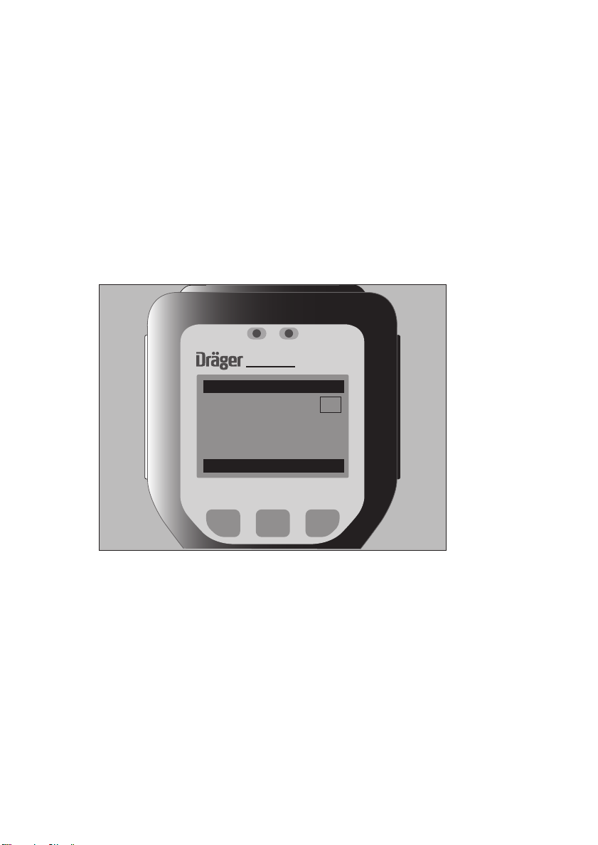
Display
The Multi-PID 2 has a graphic display for reporting detected concentration and to guide you through configuration options. All functions
of the Multi-PID 2 will be reported on the display.
Graphic Display
The Multi-PID 2 uses an 8 line graphic display. The display will always
be used for reporting detected concentration. In order to accommodate the range of concentrations the Multi-PID 2 can detect, the
meter reading will be reported using one of two resolutions. A resolution of 0.1 ppm will be used for concentrations below 100 ppm, and a
resolution of 1 ppm will be used for concentrations above 100 ppm .
ALARM CHARGE
Multi-PID 2
9/3/2006 10:09
INT
1.0
: 0.0
STEL
: 2.9
PEAK
view clear menu
TWA
PPM
: 0.1
0:05
Using the Multi-PID 2
Figure 5 – Multi-PID 2 Display
The display reports instantaneous concentration at all times when the
pump is on. In Interval mode, the display will report instantaneous
concentrations as well as REAL, STEL or TWA.
The Multi-PID 2 is designed for ease of use with a logically organized
internal menu structure/user interface.
The Multi-PID 2 User Menu is shown in Figures 6 and 7.
The Multi-PID 2 has three soft keys under the graphic LCD display,
which always show the available functions of the soft keys in any
screen.
01123958_01_en.eps
29
Page 30
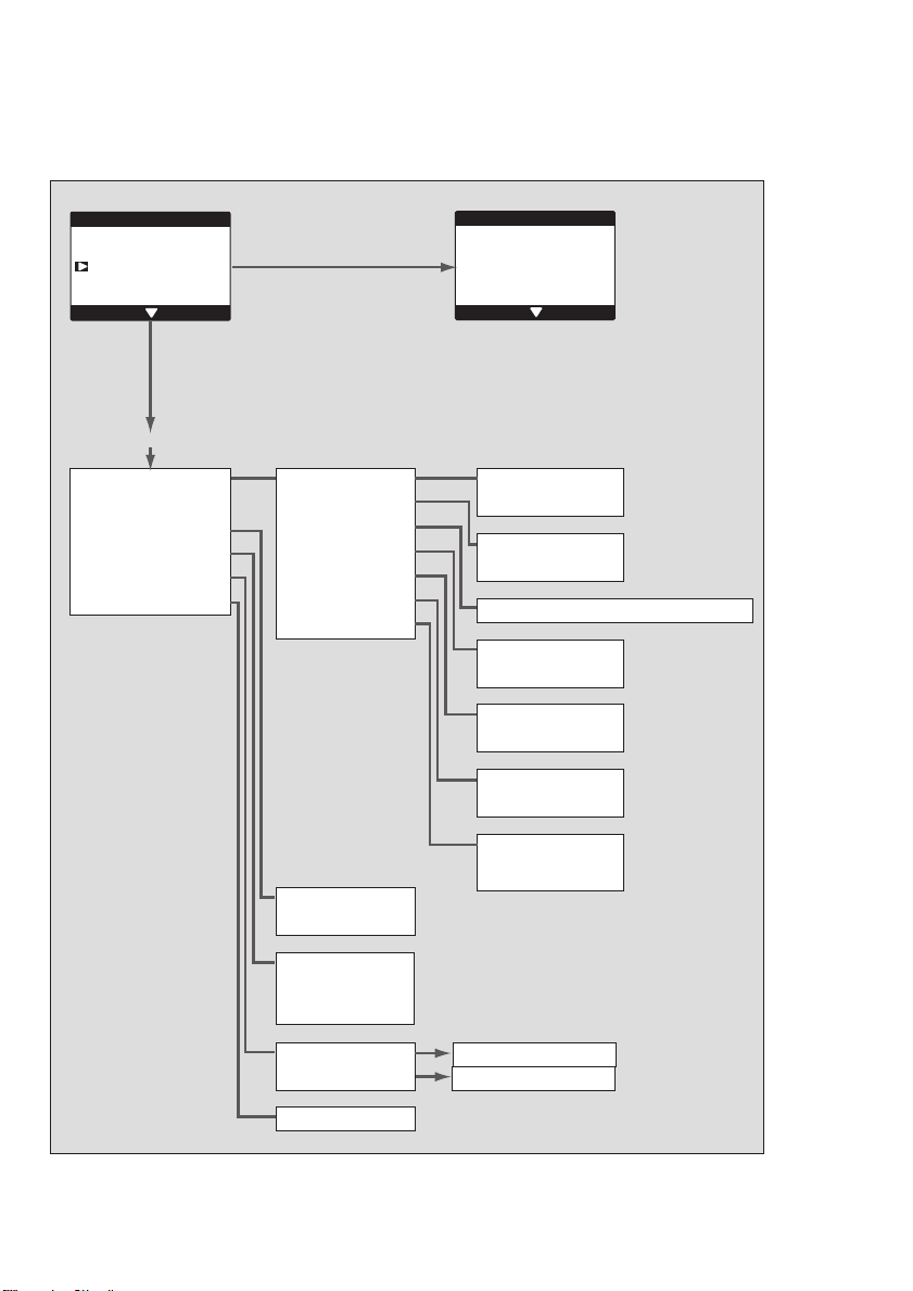
Using the Multi-PID 2
Multi-PID 2 User Menu
menu
Unit Setup
Switch to TVOC mode
Data Log Options
back select
GAS mode
Unit Setup
Switch to TVOC mode
Data Log Options
Clear values
Edit Alarms
Sample Collection
User Mode
Units
Clock
Date format
Backlight
Language
Passcode
Clear data log
Download to PC
menu
Unit Setup
Switch to GAS mode
Memory slots
back select
Logging Off
Sample
PPM
PPB
Enter current time –– Enter current date
MM/DD/YYYY
DD/MM/YYYY
on
off
English
German
Change Passcode
or lock / unlock
instrument
Figure 6 – User Menu, GAS mode
30
SMAX
STEL
ALL
STEL alarm:
REAL alarm:
Enter sample liters
Enter new STEL
Enter new REAL
02823958_01_en.eps
Page 31

Using the Multi-PID 2
menu
Unit Setup
Switch to GAS mode
Memory slots
back select
TVOC mode
Unit Setup
Switch to GAS mode
Memory slots
Data Log Options
Humidity Tube
Pump
Backlight
User Mode
Clock
Date format
Language
Passcode
Units
Sample Collection
menu
Unit Setup
Switch to TVOC mode
Data Log Options
back select
off
on
on
off
Logging off
Tag
Interval
Enter current time –– Enter current date
MM/DD/YYYY
DD/MM/YYYY
English
German
Figure 7 – User Menu, TVOC mode
1.
:
:
15.
Clear data log
Edit interval
Download to PC
Attach Tube holder
and insert new tube
Change Passcode
or lock / unlock
instrument
PPM
PPB
Enter sample liters
02923958_01_en.eps
31
Page 32

Using the Multi-PID 2
Keys
Fixed Keys
The Multi-PID 2 has two fixed keys. The first fixed key is the -key
(on/off). The second fixed key is the dedicated -key (calibration
key). Pressing the -key will start calibration in almost any mode.
CAL
The -key is used to both turn power on to the Multi-PID 2 as well
as the turn the power off. To turn on the Multi-PID 2, press the key. To turn the power off, press the -key and hold it down for 5
seconds, and then release it. This is done to prevent accidental power
off.
Soft Keys
The three soft keys on the Multi-PID 2 are located directly below the
display. Each key has varying functions for configuring the
Multi-PID 2, editing the data, and controlling the display. Since only
three soft keys are available, each function is broken down into a path.
CAL
32
Page 33

Beginning Operation
Turning the Multi-PID 2 On
1. Turn the Multi-PID 2 on by pressing the -key.
2. The Multi-PID 2 will display the instrument’s software version number. Next the Multi-PID 2 will proceed to the mode display.
3. The Multi-PID 2 has an instant-on lamp. For maximum accuracy
and stability, allow the Multi-PID 2 to warm-up for 10 minutes prior
to calibration.
Default Display
The display shows the last mode the Multi-PID 2 used. The resolution
of the display changes with the magnitude of the reading. A reading
of 0 to 99.9 will be displayed with a resolution of 0.1 ppm. A reading
greater than 99.9 will be shown with a resolution of 1 ppm. The meter
will display concentrations up to 2,000 ppm.
GAS mode:
In GAS mode, the PID pre-filter tube benzene (Order No. 81 03 511)
can be used to measure benzene, or a sample collection tube (Order
No. 67 33 011) can be filled with a defined amount of a sample.
The GAS mode is a filter tube mode. This means that all measurements require the installation of the pre-filter tube holder (83 10 093)
and of the pre-filter tubes. The PID pre-filter tube benzene which is
mounted at the head end of the tube holder and adsorbs all substances with the exception of benzene is used to selectively measure
benzene. The entire process is menu-driven. The selective benzene
measurement value is displayed after 90 seconds.
Activating the GAS mode opens a dialog which queries a device calibration. The benzene measurement screen is displayed after installation of the PID pre-filter tube benzene.:
Using the Multi-PID 2
ALARM CHARGE
1/4/2006 13:31
STEL
SMAX
2
view sample menu
Figure 8 – GAS mode Display
Benzene
: 0.0
: 0.0
0.0
SAMP
SECS
Multi-PID 2
PPM
: 01
: 90
03023958_01_en.eps
33
Page 34

Using the Multi-PID 2
The following values are displayed: benzene concentration in ppm,
STEL value, the highest benzene measurement value recorded so far
(SMAX), the amount of measurements already carried out (SAMP) –
corresponds with the amount of PID pre-filter tube benzene already
used, and the sampling interval period of 90 seconds (SECS).
Pressing the " view " key shows the Datalogger measurement values.
Pressing the " menu " key takes you back to the selection menu.
Pressing the " sample " key starts the measurement: the pump is activated and the measured air is drawn through the PID pre-filter tube
benzene for 90 seconds. The measurement status is indicated by the
flashing concentration value and by the flashing word " sampling ".
The number 90 displayed under SECS counts down to 0. So the displayed number shows the remaining measuring time. " SAMPLE
DONE " signalled in the display indicates that the measurement is finished.
The PID pre-filter tube benzene is a one-shot-device and cannot be
used for a second measurement. Repeatedly pressing the " sample "
key will call up the information that the PID pre-filter tube benzene in
use is no good and that a new PID pre-filter tube benzene must be put
into the pre-filter tube holder. Only after inserting a new tube will
pressing the " sample " key start a new measurement.
TVOC mode:
The Multi-PID 2 can power up in Logging Off, Tag, or Interval mode
depending on the mode that was set by the previous user. The current
mode is shown in the upper right-hand corner of the display.
ALARM CHARGE
9/3/2006 10:43
0.0
view clear menu
Figure 9 – Logging Off Mode Display
34
Multi-PID 2
LOG
PPM
00923959_01_en.eps
Page 35

ALARM CHARGE
Multi-PID 2
9/3/2006 10:56
TAG
0.0
view tag menu
PPM
Using the Multi-PID 2
Figure 10 – TAG Mode Display
ALARM CHARGE
9/3/2006 11:07
STEL
PEAK
view clear menu
Figure 11 – Interval Mode Display
0.0
: 0.0
: 1.0
Multi-PID 2
TWA
01023958_01_en.eps
INT
PPM
: 0.1
0:27
02723958_01_en.eps
35
Page 36

Using the Multi-PID 2
Numeric Value, Duration, Time and Date Entry
In cases where the system requires the user to enter a number, duration, time, or date, the following mechanism is used. The number of
digits to be entered depends on the type of value being entered.
Upon entering a value entry screen, a bar icon below the left most
digit highlights it as the active digit. The arrows "
ton) and "
l " (left soft button) are used to increase/ decrease the
digit. The bar icon is moved to the next digit to the right using the "
q " (middle soft but-
j "
soft button. Once the user has finished entering the value they use
the right soft button to move the bar icon to the far right to highlight
the OK check mark "
n ", the left soft button changes to » done «. The user is then able
"
n ". When the bar is under the OK check mark
to input the value. Pressing the right soft button while the OK check
n " is highlighted will return the bar icon to the left most digit.
mark "
In some cases, units may be specified (e.g., ppm or hh:mm); in others
there may be no units.
No cancel option is available to the user. They must input a value.
alarm
Enter new PEAK:
j
j
j
alarm
Enter new PEAK:
24 2 54 2 5
j
j
j
alarm
Enter new PEAK:
done
j
Enter new PEAK:
j
alarm
j
j
01223958_01_en.eps
36
Page 37

Using the Multi-PID 2
Instrument Status
The instrument status is shown on the left of the first line of the status
display. Each status has a priority assigned to it. If more than one status is in effect, then the status with the highest priority is displayed
until the condition is corrected or until the option is turned off. Table 1
is a list of the possible system alerts.
Table 1 – System Alerts
Multi-PID 2 Display Description
» Concentration for zero air too high « Zero gas too high
» Concentration for span gas too high « Span gas too low
» Pump Error « Pump fault
» UV Lamp Error « UV lamp fault
» Blocked Filter « Blocked sample inlet filter
"Low Battery" Icon Low battery
» Data log is full « Data memory full
» Unit Locked « Unit locked by passcode
» PC Connected « Instrument communicating with PC
» Sensor over range « Sample concentration over instrument
operating range
» Alarm « + R Icon Real time concentration alarm
» Alarm « + T Icon TWA concentration alarm
» Alarm « + S Icon STEL concentration alarm
System Alerts and Alarms
While operating the instrument, system alerts can occur. To accurately identify the source of the alarm, each type of alarm has been
given a unique status.
In addition to the status, the Multi-PID 2 also has an audio alarm and
an alarm LED. To conserve power, the Multi-PID 2 alternates between
the LED and audio. Different alarms are identified by the frequency at
which the Multi-PID 2 alternates between the audio and LED; REAL
alarm is 5 times per second, STEL alarm is 2.5 times per second, and
TWA alarm is 1.25 times per second.
37
Page 38

Using the Multi-PID 2
A soft key is used for acknowledging alarms and is named “ accept ”.
If no alarm exists, then the “ accept ” key is not shown. To clear the
alarm, press the “ accept ” key. Once acknowledged, the alarm indi-
cators are cleared. The alarm status will remain until the alarm condition clears.
The Multi-PID 2 updates the instantaneous concentration once every
second.
Following every update, the instantaneous concentration is compared
to the REAL alarm level, and if exceeded, an alarm is triggered.
In Interval mode, if a 15-minute average exceeds the STEL, a STEL
alarm is generated. The TWA alarm is generated when the current
average of concentration, since the TWA was last cleared, has exceeded the TWA exposure limit.
During calibration, all alarms are disabled. Once the calibration is
complete, the alarms are re-enabled.
38
Page 39

Short-Term Exposure Limit (STEL) Mode
The Short-Term Exposure Limit (STEL) mode displays the concentration as a 15-minute moving average. The Multi-PID 2 maintains
15 samples, each representing a one-minute averaging interval.
Once every minute, the oldest of the 15 samples is replaced with a
new one-minute average. This moving average provides a 15-minute
average of the last 15 minutes with a one-minute update rate. Since
the average is calculated using 15 one-minute averages, the meter
display will only update once every minute.
STEL is set to zero each time the instrument is turned on. Since STEL
is a 15-minute moving average, there is no need to clear or reset the
STEL.
STEL calculations are always being performed by the Multi-PID 2. You
can display the results of the calculations by selecting Interval Mode.
Time-Weighted Average (TWA) Mode
The TWA accumulator sums concentrations every second until 8
hours of data have been combined. If this value exceeds the TWA
alarm setting, a TWA alarm is generated. The TWA is not calculated
using a moving average. Once 8 hours of data have been summed,
the accumulation stops. In order to reset the TWA accumulator, press
the " clear " key, then select » TWA « using the "
" clear ".
This sum will only be complete after 8 hours, so the meter displays
the current sum divided by 8 hours.
TWA calculations are always being performed by the Multi-PID 2. You
can display the results of the calculations by selecting Interval mode.
l " key, then press
Using the Multi-PID 2
REAL Mode
The REAL mode displays the current detected concentration. The reading is updated once a second. In the background, the Multi-PID 2
datalogger is sampling the concentration and measuring minimum,
maximum, and average concentrations for the selected averaging
interval. At the end of every interval, one entry is placed in the datalogger until the datalogger is full.
In order to reset the REAL reading, press the " clear " key then select
» REAL « using the "
l " key then press " clear ".
39
Page 40

Using the Multi-PID 2
Preparing for Field Operation
Field Check List
When using the Multi-PID 2 for field operation, the following items
should be carried into the field to reduce or eliminate down time of
the instrument.
If you are going to be in the field for a single 8-10 hour day, then you
should include the following accessories:
Table 2 – Check List for Field Items
Spare battery pack Part No. 83 23 622
n
Spare 10.6eV lamp Part No. 83 18 307
n
Multi-PID 2 multi-tool Part No. 64 05 415
n
Short sample probe Part No. 64 05 412
n
Calibration regulator Part No. 68 10 688
n
Tank(s) of calibration gas Part No. 68 10 687
n
Spare inlet filters Part No. 83 17 681
n
Carrying case Part No. 83 17 664
n
DC power cord Part No. 64 05 421
n
Tube Holder Part No. 83 19 093
n
Dräger Charcoal Tube, Carbon filter
n
(for zero point calibration)
Dräger Tube, PID Humidity Filter Part No. 81 03 531
n
Sampling Tube (Activated Charcoal, Type BIA) Part No. 67 33 011
PID Pre-Filter Tube Benzene Part No. 81 03 511
Instrument manual Part No. 90 23 767
n
Part No. 83 17 670
Part No. CH 24 101
If you will be in the field for more than one day, you should include the
following additional items:
Table 3 – Additional Field Items
AC adapter Part No. 83 17 661
n
Cable kit Part No. 83 17 667
n
Computer and associated cables
n
40
Page 41

Operational Check List
CAUTION:
A flow test to check the tightness of the system and the
function of the flow alarm has to be performed before
each measuring mode.
Before beginning field work, set up and calibrate the Multi-PID 2 for
your particular application.
To ensure the instrument is in working order before heading into the
field:
1. Ensure the battery pack is fully charged. If you are unsure about
the status of the battery, replace the battery pack with one that is
fully charged. See battery charging on page 26.
2. Perform a flow test:
Switch on the device (pump modus starts automatically).
Block the gas inlet after 60 sec (close the hose end or hold the inlet closed). The operating noise of the pump changes audibly, it
may also stop completely.
a. Flowtest OK:
The device changes to alarm mode after a short time: "Pump
Error" is displayed on the display and a short alarm tone is
audible. Confirm the alarm by pressing the top middle key.
b. Flowtest error:
No alarm is triggered after blocking the gas inlet for 10 sec.
Switch off the device. Contact DrägerService.
3. After calibration is complete, sample the calibration gas and the
bag of zero air to ensure the Multi-PID 2 has been calibrated correctly.
4. Select the correct operating mode. See Section regarding Operation Modes page 54.
Using the Multi-PID 2
41
Page 42

Using the Multi-PID 2
42
Page 43

Connecting Accessories
Connecting Accessories
43
Page 44

Connecting Accessories
Computer
The Multi-PID 2 will download information stored in its datalogger to a
Windows
prepare reports based on the Multi-PID 2’s recorded data. This feature may also be used if you need the recorded data in a format that
can be imported into a spreadsheet or database for further calculations.
NOTE:
The Multi-PID 2 is not classified for use in hazardous locations
when connected to any computer.
The instructions below will provide you with the basic information for
using the Multi-PID 2 with the communications software Dräger GasVison. In order to use these instructions, you must be familiar with
Microsoft Windows and the software GasVision must be installed
and running on your computer.
To initiate communications between the Multi-PID 2 and a PC:
1. Turn the Multi-PID 2 off.
NOTE:
You must turn the instrument off before connecting or disconnecting the computer cable.
®
based computer. This option may be used if you need to
2. The Multi-PID 2 must be connected to a serial port. Use the computer cable (Part No. 83 17 667) to connect the Multi-PID 2 to
one of the computer’s serial ports. Remember which serial port
you are using as you will need this information when you set up the
Dräger GasVision software. Normally you will use Com1 or Com2.
3. If the Multi-PID 2 printer cable plugs directly into the port on the
computer without the gender changer or the 9 to 25-pin adapter,
you are most probably connected to a parallel port. You will need
at least one of the adapter cables to connect the Multi-PID 2 to a
serial port. Once all connections have been made, turn on the
Multi-PID 2 instrument.
4. Start the Dräger GasVision software as you would any Windows
program. The Dräger GasVision splash screen will appear on the
PC. Once the Dräger GasVision software is running, the PC is ready to receive data from the Multi-PID 2.
5. On the Multi-PID 2, the number of data bits has been fixed at 8,
stop bits has been fixed at 1. Parity has been set at None and the
Flow control is Xon/Xoff. These values are set automatically by the
Dräger GasVision software.
44
®
Page 45

6. On the Multi-PID 2, press the " menu " key, choose » Data Log
Options «, then press the " select " key.
7. Choose the » Download to PC « option using the "
l " key and
press the " select " key.
8. Follow the Multi-PID 2 prompts to start the data download.
NOTE:
A DB-25, female connector is sometimes a parallel port. Do not
connect the serial port of the converter to a parallel port.
Pre-filter Tube Holder
The optional pre-filter tube holder (Order No. 83 19 093) is shown in
figure 12. The pre-filter tube holder is designed to hold the optional
charcoal pre-filter tube (Order No. CH 24 101) for calibration in clean
air, the optional PID pre-filter tube humidity (Order No. 81 03 531) to
enhance the measuring performance in TVOC mode by reducing the
humidity, the optional sampling tube with activated carbon (Order No.
67 33 011) and the PID pre-filter tube benzene (Order No. 81 03 511)
for selective benzene measurement in GAS mode.
The tube holder attaches to the Multi-PID 2 on the inlet nozzle replacing the standard inlet nozzle cap. It is a simple twist lock application.
Connecting Accessories
Figure 12 – Tube Holder
To insert a pre-filter tube into the tube holder:
1. Unscrew the top part of the tube holder immediately above the
tube window.
2. Break off each end of the glass tube by inserting the end into the
opening as shown.
3. Insert tube into holder.
4. Re-screw on the top part of the tube holder (note: the tube holder
is designed to compensate for any minor irregularities in the tube
that result from the breaking off of each end).
02523957_01_de.eps
45
Page 46
Connecting Accessories
To remove a pre-filter tube from the tube holder:
1. Unscrew the top part of the tube holder immediately above the
tube window.
2. Lift the pre-filter tube from the tube holder.
3. Either insert another tube or re-attach the top part of the tube holder.
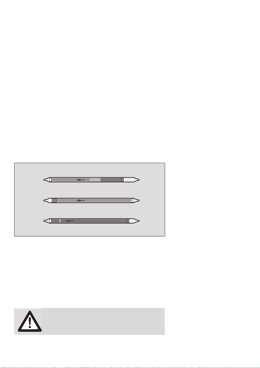
Pre-filters and Sample Collection Tubes
Dräger Safety provides a variety of pre-filter tubes for the Multi-PID 2.
The tubes are custom developed for Dräger Safety AG & Co., and
address clean air calibration and humidity reduction to facilitate more
accurate sampling.
The optional sample collection tubes are standard Dräger tubes used
for collecting VOC samples for analysis later in a lab or other analytic
facility.
Figure 13 – Dräger Pre-filter Tubes
Sample Line
A 3-meter (9’) sample line (Part No. 64 05 411) may be connected to
the Multi-PID 2 for remote sampling. Connect the sample line to the
Multi-PID 2 inlet using the fittings supplied with the sample line.
CAUTION:
When using the sample line, be especially careful
not to aspirate liquids or solids as they will damage
the Multi-PID 2.
46
02623957_01_de.eps
Page 47

Wrist Strap
To use the wrist strap:
● Turn off the Multi-PID 2 and then remove the battery cover. See
Removing and Replacing the Battery Pack on page 26.
● Place the metal ring of the wrist strap in the circular notch located
on the battery door.
● Replace the battery cover.
● Adjust the strap length as necessary.
DC Power Cord
The Multi-PID 2 can be connected to a car battery through the cigarette lighter with the DC power cord. While the Multi-PID 2 is connected to the car battery, the Multi-PID 2 battery is being charged.
WARNING:
The 2Multi-PID 2 is not classified for use in hazardous locations with a DC power cord, danger of an
explosion!
Connecting Accessories
To connect the Multi-PID 2 to a DC power supply:
1. Turn the instrument off by pressing the ON/OFF key for five seconds.
2. Connect the DC power cord (Part No. 64 05 421) to the MultiPID 2 AC adapter jack on the rear of the instrument.
3. Connect the other end of the DC power cord to the cigarette lighter in the car.
4. Turn the instrument on again by pressing the ON/OFF key.
If the vehicle is running, ensure the engine exhaust does not contaminate your samples.
Belt Clip Holster
Use the belt clip holster (Part No. 83 17 677) to protect the instrument and to mount the instrument to a belt.
47
Page 48

Connecting Accessories
11.7 eV UV Lamp
General Information
The Multi-PID 2 is equipped with a standard 10.6 eV UV lamp. An
11.7 eV UV lamp (Part No. 83 18 317) is available for special applications.
Install this lamp as outlined in Removing and Replacing the UV Lamp
on page 80. When you install a UV lamp other than the standard
10.6 eV lamp, all the response factors become invalid. You must set
the response factor for the current cal memory to 1. Contact Dräger
Safety’s Applications Department for further information.
NOTE:
Do not use the 11.7 eV lamp in conjunction with the dilution
probe.
Limitations of Lithium Fluoride Lamp Window
This lamp is intended for special applications only. It is not suitable for
normal operation, due to limitations of the lamp window material.
The 11.7 eV lamp window material is lithium fluoride (LiF). LiF is composed of two light elements which are easily disrupted within the crystal lattice by the UV light generated by the lamp. Disruption of the
lattice causes the crystal to turn a yellowish color, and again performance declines.
Unlike other lamp windows, LiF readily absorbs water from atmospheric humidity. When contaminated by moisture, the window loses its
ability to transmit UV light.
WARNING:
Do not touch the lamp window or handle it near
water.
Using the 11.7 eV UV Lamp
With an 11.7 eV lamp installed, your instrument functions as a detector responding to compounds which ionize at 11.7 eV or less. The
11.7 eV lamp may be useful for detecting compounds not ionized by
the standard 10.6 eV lamp.
Due to the lamp window limitations, the lifetime of the 11.7 eV lamp is
restricted and it must be used sparingly according to the following
instructions.
48
Page 49

To use the 11.7 eV lamp in your the Multi-PID 2:
1. Remove the 11.7 eV lamp from the supplied desiccant bottle and
install the lamp as outlined in Removing and Replacing the UV
Lamp on page 80.
WARNING:
Do not remove or replace any detector lamp in a
hazardous location, danger of an explosion!
2. Turn the instrument on and wait for the ready status. If the lamp
cannot be started, contact Dräger Safety’s Technical Support Department.
3. Calibrate the Multi-PID 2. See Calibration Using the Flow-Match
Regulator on page 76.
4. All response factors are invalid when an 11.7 eV lamp is installed.
The response factor must be set to 1.
5. Recalibrate the instrument every 15 minutes of operation.
6. Every hour of operation, switch off the instrument, remove the
lamp and examine the window for yellowing. If the window is yellow, then regenerate the window according to the procedure in
Cleaning the Lithium Fluoride Window on page 83.
7. After use, remove the lamp and store it in the supplied desiccant
bottle.
Do not leave the 11.7 eV lamp in the instrument when you turn it off.
Always remove the 11.7 eV lamp and store it in the supplied desiccant
bottle
Connecting Accessories
49
Page 50

Connecting Accessories
Off-Line Charger
General Information
The off-line charger (Part No. 64 05 404) allows you to charge a battery pack independently of the Multi-PID 2. To charge a battery pack
without removing it from the Multi-PID 2, see Battery Charging on
page 26.
The off-line charger requires one of the following the Multi-PID 2
accessories for operation:
AC Adapter Part No. 64 05 428 (North America)
AC Adapter Part No. 83 17 661 (Europe)
DC Power Cord Part No. 64 05 421
Use only the AC adapter specified for use with the Multi-PID 2. Using
another AC adapter will result in damage to the battery pack, the offline charger, or the adapter.
Charging from an AC Source
WARNING:
Do not charge the battery pack in a hazardous location, danger of an explosion!
To re-charge your battery pack:
1. Remove the battery pack as outlined in Battery Charging on page
26.
2. Attach the connector from the battery pack to the socket on the off
line charger.
NOTE:
The connector is polarized. It will only fit one way. Do not force
the connection.
3. Plug the AC adapter into the jack on the opposite face of the offline charger.
4. Plug the AC adapter into an AC outlet. If you are using the European AC adapter, ensure the correct plug is installed on the line
cord. If it is not correct for the wall outlet in your area, then it must
be replaced.
5. The LED on the upper face of the off-line charger indicates the
charge state of the battery pack. Red indicates the battery is being
charged. Green indicates the battery is fully charged.
6. Charging a fully discharged battery pack will take approximately
four hours.
50
Page 51

7. It is normal for a fully charged battery pack to indicate it is charging
(red light) when first plugged in. The LED will turn green within a
few minutes to indicate the battery is fully charged.
8. When the battery pack is fully charged, remove the AC adapter,
first from the wall outlet, then from the off line charger.
9. Remove the battery pack connector from the socket on the off-line
charger.
10. Replace the battery pack in the Multi-PID 2 as outlined in Removing and Replacing the Battery Pack on page 26.
You can keep the battery pack fully charged indefinitely, without overcharging it, by leaving it connected to the off-line charger while the
charger is operating.
Charging from a DC Source
To re-charge your battery pack:
1. Remove the battery pack as outlined in Removing and Replacing
the Battery Pack on page 26.
2. Attach the connector from the battery pack to the socket on the offline charger.
NOTE:
The connector is polarized. It will only fit one way. Do not force
the connection.
Connecting Accessories
3. Plug the DC power cord into the jack on the opposite face of the
off-line charger.
4. Plug the DC power cord into a vehicle auxiliary 12 VDC or cigarette lighter socket.
5. The LED on the upper face of the off line charger indicates the
charge state of the battery pack. Red indicates the battery is being
charged. Green indicates the battery is fully charged.
6. Charging a fully discharged battery pack will take approximately 4
hours.
7. It is normal for a fully charged battery pack to indicate it is charging
(red light) when first plugged in. The LED will turn green within a
few minutes to indicate the battery is fully charged.
8. When the battery pack is fully charged, remove the DC power
cord, first from the vehicle auxiliary 12 VDC or cigarette lighter
socket, then from the off-line charger.
9. Remove the battery pack connector from the socket on the off-line
charger.
10. Replace the battery pack in the Multi-PID 2 as outlined in Battery
Charging on page 26.
You can keep the battery pack fully charged indefinitely, without overcharging it, by leaving it connected to the off line charger while the
charger is operating.
51
Page 52

Connecting Accessories
52
Page 53

Menu Functions
Menu Functions
53
Page 54

Menu Functions
User Interface – Basic Menu
The Multi-PID 2 is designed for ease of use with a logically organized
internal menu structure/user interface. The Multi-PID 2 User Menu is
shown in Figures 6 and 7 on page 30 and page 31.
The Multi-PID 2 has three soft keys under the graphic LCD display
which always show the available functions of the soft keys in any
screen.
Operation Modes
GAS mode
The GAS mode is a filter tube mode. This means that all measurements require the installation of the pre-filter tube holder and of the
pre-filter tubes. In this selective measuring mode, the PID pre-filter
tube benzene which is mounted at the head end of the pre-filter tube
holder and adsorbs all substances with the exception of benzene is
used to selectively measure benzene. The entire process is menudriven. The selective benzene measurement value is displayed after
90 seconds.
Activating the GAS mode opens a dialog which queries a device calibration. The benzene measurement screen is displayed after installation of the PID pre-filter tube benzene. The following values are
displayed: benzene concentration in xx ppm, STEL value, the highest
benzene measurement value recorded so far (SMAX), the amount of
measurements already carried out (SAMP) – corresponds with the
amount of PID pre-filter tube benzene already used, and the sampling
interval period of 90 seconds (SECS).
Pressing the " view " key shows the Datalogger measurement values.
Pressing the " menu " key takes you back to the selection menu.
Pressing the " sample " key starts the measurement: the pump is activated and the measured air is drawn through the PID pre-filter tube
benzene for 90 seconds. The measurement status is indicated by the
flashing concentration value and by the flashing word " sampling ".
The number 90 displayed under SECS counts down to 0. So the displayed number shows the remaining measuring time. " sample
done " signalled in the display indicates that the measurement is finished.
The PID pre-filter tube benzene is a one-shot-device and cannot be
used for a second measurement. Repeatedly pressing the " sample "
key will call up the information that the PID pre-filter tube benzene in
use is no good and that a new PID pre-filter tube benzene must be put
into the pre-filter tube holder. Only after inserting a new tube will
pressing the " sample " key start a new measurement.
54
Page 55

TVOC mode
In TVOC mode, the Total Volatile Organic Compounds are detected.
Changing the Operating Mode
1. Press the " menu " key.
2. Use the "
to TVOC mode " , then press " select ".
l " key to select " Switch to GAS mode " resp. " Switch
Menu Functions
Unit Setup Menu
Unit setup functions are used to select the Multi-PID 2 features. There
are nine functions which can be set on the Multi-PID 2; » Pump «,
» Backlight «, » User Mode «, » Clock «, » Date format «,
» Language «, » Passcode «, » Units «, and » Sample Collection «.
Figure 14 shows a menu detailing the User Setup functions. Press
the " menu " key in any operating mode to access » Unit Setup «.
55
Page 56

Menu Functions
GAS mode
Unit Setup
TVOC mode
Unit Setup
Figure 14 – Unit Setup Map
User Mode
Units
Clock
Date format
Backlight
Language
Passcode
Pump
Backlight
User Mode
Clock
Date format
Language
Passcode
Units
Sample Collection
Logging Off
Sample
PPM
PPB
Enter current time –
Enter current date
MM/DD/YYYY
DD/MM/YYYY
on
off
English
German
Change Passcode
or lock / unlock
instrument
off
on
on
off
Logging Off
Tag
Interval
Enter current time –
Enter current date
MM/DD/YYYY
DD/MM/YYYY
English
German
Change Passcode
or lock / unlock
instrument
PPM
PPB
Enter sample liters
01323958_01_en.eps
56
Page 57

Pump
Only available in TVOC mode.
The function » Pump « turns the pump on and off.
The detector is turned off when you turn the pump off. This prevents
the detector from being damaged when there is no sample flowing
through the detector.
When the pump and the detector are off, the meter display will continue to read normally but the instantaneous reading is at 0.0. Turn the
pump and detector off when concentration measurements are not
necessary, and the Multi-PID 2 will only be used for setup or
reviewing data. By operating the instrument with the pump and detector off when you do not need them, you will conserve the battery and
ultraviolet (UV) lamp.
To turn the pump on:
1. Press the " menu " soft key, » Unit Setup «, press " select ",
» Pump «, press " select ", " on ", then press " select ".
To turn the pump off:
2. Press the " menu " soft key, » Unit Setup «, press " select ",
» Pump «, press " select ", " off ", then press " select ".
Menu Functions
Backlight
The function »Backlight « is used to switch the backlighting on and
off when there is insufficient light to read the display.
Switching on the backlight:
1. Press the " menu " key. Select " Unit Setup ", then press
" select ". Select " Backlight ", then press " select ". Select
" on ", then press " select ".
Switching off the backlight:
2. Press the " menu " key. Select " Unit Setup ", then press
" select ". Select " Backlight ", then press " select ", select
" off ", then press " select ".
To extend the operating life of the battery pack, turn the backlighting
off when it is not required.
57
Page 58

Menu Functions
User Mode
The " User Mode " function selects one of the offered logging
modes. The logging modes are:
In GAS mode – " Logging off " and " sample ".
In TVOC mode – " Logging off ", " Tag " and " Interval ".
» Logging off «
Logging Off mode is identified by the word » LOG « with a diagonal
line through the word » LOG « in the upper right corner of the
Multi-PID 2 display. Logging Off will continuously display the concentration of total volatile compounds present that the Multi-PID 2 can
ionize. The reading is updated approximately once per second. In
Logging Off mode, the only soft key displayed is " menu ".
" menu " selects the Multi-PID 2’s internal menu for the instrument
setup by the user.
Activating " Logging off ":
1. Press the " menu " key and select " Unit Setup ", then press
" select ". Select " User Mode ", then press " select ".
2. Select " Logging Off ", then press " select "
In this mode, the only soft key displayed is the " menu " key.
" menu " selects the Multi-PID 2’s internal menu for the Multi-PID 2
setup by the user.
» Sample «
Only available in GAS mode.
This function starts the measurement with the PID pre-filter tube benzene = benzene measurement. See also page 33 and page 54.
Activating " sample " mode:
1. Press the " menu " key and select " Unit Setup ", then press
" select ". Select " User Mode ", then press " select ".
2. Select " sample ", then press " select "
In this mode, the soft keys " view ", " sample " and " menu " are
active.
Pressing the " view " key shows the latest measured values stored in
the Datalogger.
Pressing the " sample " key starts a new benzene measurement.
" menu " selects the Multi-PID 2’s internal menu for the Multi-PID 2
setup by the user.
58
Page 59

» TAG «
Tag mode is identified by the word » TAG « in the upper right-hand
corner of the Multi-PID 2 display. Tag mode will continuously display
the instantaneous concentration of total volatile compounds. Tag
mode also allows the user to manually tag and datalog readings. Tag
mode allows the user to datalog a background reading, a sample reading and assign Site Codes to readings. Site Codes are set using the
Dräger GasVision software. See “Connecting Accessories” on
page 43., for more information on how to use the Dräger GasVision
software. In Tag mode, the soft keys are " view ", " tag " and
" menu ".
Activating " tag " mode:
1. Press the " menu " key and select " Unit Setup ", then press
" select ". Select " User Mode ", then press " select ".
2. Select " tag ", then press " select "
In this mode, the soft keys " view ", " tag " and " menu " are active.
" view " selects datalogger review.
" tag " selects “No Label”, “Background”, or “Sample”.
" menu " selects the Multi-PID 2’s internal menu for the Multi-PID 2
setup by the user.
Menu Functions
» Interval «
Interval displays the instantaneous readings as well as STEL, TWA,
and REAL readings. Interval mode is identified by the letters » INT « in
the upper right-hand corner of the Multi-PID 2 display. Interval automatically calculates and updates STEL, TWA, and REAL readings.
Interval mode also automatically stores these readings in the
Multi-PID 2’s memory at a preset interval selected by the user. In interval mode data is logged at a user selected interval value between
3 seconds and 900 seconds.
The microprocessor accumulates all readings in an averaging interval
that you select, and determines the minimum, average and maximum
readings. It stores these numbers along with the highest priority
instrument status and the most recent time and date.
These recorded data can now be reviewed and edited. Recorded
data can also be printed using the PC. For each averaging interval,
the Multi-PID 2 prints the minimum of all the minima, the average of all
the readings for the interval and the maximum of all the maxima.
59
Page 60

Menu Functions
In STEL mode, 15 samples are combined to form a 15-minute average. Once every minute, the oldest of the 15 samples is replaced with
a new one-minute average. This moving average provides a 15-minute
average with a one-minute update rate so the meter display will only
update once every minute. STEL is set to zero each time the instrument is turned on.
STEL calculations are always being performed by the Multi-PID 2. You
can display the results of the calculations by selecting STEL as the
Display mode.
In REAL mode, the reading is updated once a second. In the background, the Multi-PID 2 datalogger is sampling the concentration and
measuring min, max, and average concentrations for the selected
averaging interval. At the end of every interval, one entry is placed in
the datalogger until the datalogger is full.
TWA mode sums concentrations every second until 8 hours of data
have been accumulated. Once 8 hours of data have been summed,
the accumulation stops.
This sum will only be complete after 8 hours, so the meter displays
the current sum divided by 8 hours. While you are in TWA mode, the
time on the status display will show the number of minutes and hours
of data that TWA has accumulated. When this reaches 8 hours, the
Multi-PID 2 stops accumulating data and the TWA is complete.
TWA calculations are always being performed by the Multi-PID 2. You
can display the results of the calculations by selecting TWA as the
Display mode.
Interval mode logs readings at user-selected intervals of 3 seconds to
900 seconds.
60
Page 61

ALARM CHARGE
Multi-PID 2
Intervals
Enter new
INTERVAL (sec)
0 0 1 5
l
q
✓
j
Menu Functions
Figure 15 – Intervall time adjustment
Interval simultaneously displays the STEL, TWA, and REAL reading
along with the instantaneous reading. The Multi-PID 2’s Datalogger
can store up to 15000 entries. The interval you select will determine
the period of operation. At the end of the period, the datalogger will
be full and you will see the “Data Log Full” status.
Table 4 – Averaging Intervals and Period STEL, TWA, and REAL Operation
Averaging Interval
(example)
15 s 50
1 m 200
2 m 400
5 m 1000
15 m 3000
The Multi-PID 2’s display can show four values in Interval mode:
STEL, TWA, and REAL, plus the instantaneous reading.
Activating " Interval " mode:
1. Press the " menu " key and select " Unit Setup ", then press
" select ". Select " User Mode ", then press " select ".
2. Select " Interval ", then press " select "
Hours of Operation to
Fill the Datalogger
00323958_01_en.eps
61
Page 62

Menu Functions
In Interval mode, the soft keys are " view ", " clear " and " menu ".
" view " selects datalogger review.
" clear " shows the selection options " TWA " " REAL ", or " ALL ".
Use the "
" clear " to delete the stored data of the corresponding option.
" menu " selects the Multi-PID 2’s internal menu for the Multi-PID 2
setup by the user.
Clock The function » Clock « is used to set both the current date and time.
Entering Numbers with the Soft Keys to Set the Clock
For all information that you must enter, the left, center and right soft
keys correspond to the "
ting the Time” on page 62..
The "
by the cursor. The "
character on the right. When the cursor is advanced past the right
most character or symbol "
again. To accept the changes, press the " done " soft key when the
checkmark is highlighted.
l " key to select one of the selection options, then press
l ", " q " und " j " arrow, “Figure 16 – Set-
l " und " q " keys are used to change the character highlighted
j " key is used to advance the cursor to the next
n ", it wraps around to the first character
ALARM CHARGE
Enter current time
Figure 16 – Setting the Time
62
l
set time
10 : 12
q
Multi-PID 2
✓
j
01423958_01_en.eps
Page 63

To set the time and date:
1. Press the " menu " soft key.
2. With » Unit Setup « highlighted, press the " select " soft key.
3. Using the "
soft key.
The "
derlined by the cursor. The "
to the next character on the "right. When the cursor is advanced
past the right most character, it wraps around to the first character
again.
Formatting characters, such as the colon » : « in the time, the decimal » . « in a concentration, and the slash » / « in date are skipped
when advancing the cursor.
4. Use the "
formatted as Hour:Minute.
5. Use the "
highlighted. Press the " done " soft key to confirm the time and
move to the date option.
6. When setting the date, the Multi-PID 2 prompts you for the current
date formatted as Month/Day/Year. Use the "
to enter the correct date.
7. Press the " done " soft key to confirm the date and the display will
return to the main screen.
l " soft key, highlight » Clock «. Press the " select "
q " and " l " soft keys are used to change the character un-
j " key is used to advance the cursor
q " and " l " keys to enter the correct time. The time is
j " soft key until the checkmark " n " on the display is
q " " l " and " j "
Menu Functions
Date Format Use the " Date format " function to select the displayed date format
" MM/DD/YYYY " or " DD/MM/YYYY ".
Selecting a format:
1. Press the " menu " key and select " Unit Setup ", then press
" select ", and select " Date format ", then press " select " and
select date format, then press " select ".
Language Use the " Language " function to select the displayed language
" English " or " German ".
Selecting a format:
1. Press the " menu " key and select " Unit Setup ", then press
" select ", and select " Language ", then press " select " and select the language, then press " select ".
63
Page 64

Menu Functions
Passcode
The " Passcode " function can be used to change the passcode as
well as to activate or de-activate the menu function block.
The " lock " function is used to prevent access to the Multi-PID 2’s
sensitive options. Sensitive options are those which can affect the
Multi-PID 2’s readings. If any of these functions is selected when the
instrument is locked, the Multi-PID 2 will prompt you to unlock the
instrument before you can access the functions.
The " unlock " function is used to obtain access to the Multi-PID 2’s
sensitive options.
The " change " function can be used to change the set passcode.
The unit always has a passcode in force. When shipped from the fac-
tory, the code is 0000.
1. Press the " menu " soft key. Highlight » Unit Setup « and press
the " select " soft key. Use the "
» Passcode «, the press the " select " soft key.
2. Choose either " unlock ", " change " or " lock " soft keys. You will
be prompted for a passcode. Using the "
keys, enter the passcode. Press the "
n " is highlighted and select the " done " soft key.
mark "
NOTE:
If you change the passcode, make sure you record the setting. If
you cannot remember your passcode once the instrument is lokked, there is no way to unlock it without losing all your data log
contents. Unlocking the instrument without a password is
accomplished by doing a reset or “cold start”. To do the reset,
hold the middle-upper key while turning the instrument on with
the on/off key.
l " soft key to highlight
q " " l " and " j " soft
j " soft key until the Check-
Units
The " Units " function can be used to select the unit of the displayed
measurement value:
" PPM " (parts per million) and " PPB " (parts per billion).
1. Press the " menu " key. Highlight " Unit Setup ", then press
" select ". Use the "
" select ".
2. Select either " PPM " or " PPB ", then press " select ".
64
l " key to highlight " Units ", then press
Page 65

NOTE:
To utilize the » Mg/M3 « unit of measure, the instrument must be
configured and operated with a compound chosen from the
Multi-PID 2’s Preset RF library because a molecular weight value
is needed for the » Mg/M3 « calculation. If you wish to use the
» Mg/M3 « unit of measure while doing TVOC work, you should
use a memory slot with Isobutylene selected from the Preset RF
library. Refer to Section: Response Factors and Memory Slots
for further information.
Sample Collection
The " Sample Collection " function is used to suck a defined air volume through the device, e.g. to fill a preceding sampling tube (sampling tube with activated carbon 67 33 011) or a gas-sampling tube
with a defined air volume. The sampling tube or the air collected using
the gas-sampling tube can be later analysed in a lab. This process is
menu-driven. The desired air volume in litres can be adjusted using
the arrow keys. It takes three minutes to take a sample of one litre.
In TVOC mode, the " Sample Collection " function is in the " Unit
Setup " menu. In Gas mode, this function is in the main menu.
Menu Functions
1. Press the " menu " key. Highlight " Unit Setup ", then press
" select ". Use the "
then press " select ".
2. Use the arrow keys "
3. Press " done " to accept the set value.
l " key to highlight " Sample Collection ",
q " and " l " to set the value.
Memory slots Menu
Only available in TVOC mode.
General Information
The response of a PID to a compound is dependent on its ionization
potential. In certain situations when the user is confident that only a
single specific compound exists, they can set up the Multi-PID 2
using an isobutylene calibration to mimic the Multi-PID 2 response as
if the Multi-PID 2 was calibrated using that specific single compound.
In situations where only a single pure compound is present in air, the
Multi-PID 2 should be calibrated with a standard of that specific compound as span gas.
65
Page 66

Menu Functions
NOTE:
In the case of calibration or when changing the configuration,
the data logger has to be deleted manually to ensure consistant
data.
The Multi-PID 2’s 15 memory slots can be used to store calibration
information for 15 different span gases.
The Multi-PID 2 will always detect all ionizable compounds present in
a sample regardless of the response factor (RF) selected.
NOTE:
Even if the Multi-PID 2 has been calibrated with a specific compound, its response is not specific and the presence of another
ionizable impurity may render the numerical result invalid.
It is often impractical to carry a range of different standards into the
field. Approximate results can be obtained by calibrating the MultiPID 2 with the recommended span gas and entering the appropriate
response factor.
The response factor is based on the ratio of the response of the specific compound to the response of the span gas. The response factor
multiplies the Multi-PID 2’s reading, then displays and records it. See
table 5 on page 97 for response factors. This list should be used only
for concentrations up to 500 ppm of the specific compound, as
response factors change with concentration.
66
WARNING:
The Multi-PID 2 is a total VOC instrument and will
ALWAYS respond to all ionizable compounds present in a sample. The Multi-PID 2 will NEVER
respond only to a specific compound if an RF is programmed. It is the responsibility of the user to be
aware of the limitations of PID instruments
Page 67

Response Factors and Memory Slots
Memory slots
1.
2.
3.
:
:
15.
“ edit ”
“ select ”
“ preset ”
A - B
C - D
E - G
H - I
J - N
O - S
T - Z
Menu Functions
“ edit ”
or
“ select ”
“ edit ”
Display selected slot
settings
“ done “
Figure 17 – Function Memory Slots Settings
Name:
RRF:
STEL alarm:
TWA alarm:
REAL alarm:
Formula Wt:
Response factors built into the Multi-PID 2 are used to correct for the
response of the PID to a specific compound. These correction factors
are often called response factors (RF). The Multi-PID 2 has 15
memory slots. Each memory slot can store one preset RF. Library/RF
selections simplify Memory Slot programming and provide standard
response factors for approximately 100 compounds. The selection
allows you to select an entry from a pre-programmed library. The
name " Name ", response factor " RRF ", the three alert levels
" STEL ", " TWA " and " REAL " and the formula " FWt " are all set
from the library.
To select a preset to program the selected Memory Slot:
1. Press " menu ", then use the "
l " key to highlight " Memory
Slots ", then press " select ".
To select a memory slot:
Press the "
l " key until the memory slot you wish to use is high-
lighted. Press the " select " key.
The name of the compound, RRF, STEL, TWA, REAL and FWt are
displayed for a few seconds for this memory slot. Press " done "
to return to the main menu.
Enter new Name
Enter new RRF
Enter new STEL
Enter new TWA
Enter new REAL
Enter new FW
01523958_01_en.eps
To edit a memory slot:
1. Press " menu ", then use the "
l " key to highlight " Memory
Slots ", then press " select ".
2. Use the "
l " key to select the memory slot, then press " select "
to display the memory slot contents. Press " done " to return to the
main menu.
67
Page 68

Menu Functions
or
3. Use the "
change the values for RRF, STEL, TWA, REAL and FWt.
4. Press " edit ", then highlight either Name, RRF, STEL, TWA,
REAL or FWt using the "
5. Use the "
6. Highlight the "
7. Press the " done " key to return to the main display or press
" select " to edit another value.
8. To return to the main menu, press " select ", then " done ".
To select a pre-programmed compound stored in the Multi-PID 2’s
Preset RRF library:
1. Press " menu ", then use the "
Slots ", then press " select ".
2. Use the "
display the memory slot contents.
3. Press " preset ".
4. Use the "
interest, then press the " select " key.
6. Choose the compound of interest using the "
the " select " key.
7. Press the " back " key to accept the choice or press " edit " to
modify the preset values for RRF, STEL, TWA, REAL and FWt as
shown above.
NOTE:
If a target gas calibration is required, a new storage location
with a response factor of 1 has to be created. It should be noted
that all storage places are calibrated simultaniously. In the case
of a target gas calibration, only the created storage place
should be used. Please refer also to chapter “Calibration Technical Description” on page 72.
l " key to select the memory slot, then press " edit " to
l " key, then press " select ".
q " " l " and " j " keys to enter the desired number.
n " checkmark, then press " done ".
l " key to highlight " Memory
l " key to select the memory slot, then press " edit " to
l " key to choose the alpha range of the compound of
l " key and press
Data Log Options Menu
The " Data Log Options " function can be used for the following functions:
" Clear data log ", " Edit interval " (only in TVOC mode) and
" Download to PC " .
68
Page 69

Clear Data Log
The " Clear data log " function clears all measurement values in the
Multi-PID 2 memory.
NOTE:
Deleted information cannot be recovered. You should play back
and print or download the contents of the datalogger before
deleting any information.
To empty the data logger in the Multi-PID 2:
1. Press the " menu " key.
2. Use the "
press the " select " key.
3. Choose » Clear data log «, and then press the " select " key.
4. Press either the " yes " or " no " key in response to » Are you sure
you want to clear all data? «.
Edit interval
Only available in TVOC mode.
1. Press the " menu " key.
Use the "
" select ".
3. Highlight " Edit interval ", then press " select ".
4. Use the "
interval.
5. Highlight the "
l " key to choose » Data Logger Options «, and then
l " key to highlight " Data Logger Options ", then press
q " " l " and " j " keys to enter the desired sampling
n " checkmark, then press " done ".
Menu Functions
Download to PC
The " Download to PC " function starts the download of data from the
Multi-PID 2 onto the PC. The Multi-PID 2 computer cable, Part No.
83 17 667, must be connected between the Multi-PID 2 and the PC
before beginning the data download. The Dräger GasVision software
must be installed and running on the PC prior to download.
To download data:
1. Press the " menu " key.
2. Use the "
the " select " key.
3. Use the "
" select " key.
4. Press the " next " key at the » Connect Instrument to PC «
prompt.
5. The display will show » Downloading Data « and data will now
download to the PC. Press the " done " key to stop the download
at any time.
l "-key to choose » Data Logger Options « the press
l " key to choose » Download to PC «, then press the
69
Page 70

Menu Functions
Clear values Menu
Only available in GAS mode.
The " Clear values " function can be used to clear the latest measurement values for the highest measured concentration (SMAX), the latest STEL value or all values (ALL) which are shown in the display.
1. Press " menu ", then use the "
values ", then press " select ".
2. Selecting the values and pressing the " clear " key clear the highlighted values.
l " key to highlight " Clear
Edit Alarms Menu
Only available in GAS mode.
The " Edit Alarms " function can be used to edit the latest set alarm
values for the STEL and the REAL alarm.
1. Press " menu ", then use the "
Alarms ", then press " select ".
2. Use the "
then press " select ".
3. Use the "
5. Highlight the "
l " key to highlight " STEL alarm " or " REAL alarm ",
q " " l " and " j " keys to enter the desired value.
n " checkmark, then press " done ".
l " key to highlight " Edit
Humidity Tube Menu
Only available in TVOC mode.
The " Humidity Tube " function can be used in combination with a
PID pre-filter tube humidity (Order No. 81 03 531) to enhance the
measuring performance by reducing the humidity.
This tube is used to measure the Total Volatile Organic Compounds
value (TVOC) for 15 minutes (filter capacity of the tube at 40
100 % relative humidity). Then you are asked to check the tube and to
replace it, if necessary.
1. Press " menu ", then use the "
Tube ", then press " select ".
70
l " key to highlight " Humidity
o
C and
Page 71

Routine Maintenance
Routine Maintenance
71
Page 72

Routine Maintenance
Maintenance Intervals
The device should be calibrated before measuring, especially if it was
not used for a longer period of time.
If used, the 11.7 eV lamp should be replaced approx. every six
months.
Calibration Technical Description
Periodic calibration is required to compensate for the Multi-PID 2 output changes due to inlet filter restriction, ionization chamber contamination, lamp cleanliness, pump wear and other factors.
During calibration, the Multi-PID 2 is first exposed to zero air. A small
(zero) signal is generated. This zero signal is stored by the microprocessor.
The Multi-PID 2 is next exposed to span gas. This span gas signal is
stored by the microprocessor. The microprocessor subtracts the zero
signal from the span gas signal and divides the difference by the userentered span gas concentration. The resulting sensitivity is stored in
the selected Memory Slots with the zero signal and the alarm levels.
This number is then multiplied by the response factor and displayed.
The Multi-PID 2 readings are always relative to the calibration gas.
After calibration with isobutylene, the Multi-PID 2 will respond directly
in units equivalent to isobutylene. Most volatile organic compounds
will be detected by the Multi-PID 2.
It cannot distinguish between isobutylene and other ionizable compounds. A reading of 10 ppm indicates all ionizable compounds that
are present have generated an ion current proportional to 10 ppm of
isobutylene. The reading is actually 10 ppm isobutylene equivalent
units. The Multi-PID 2 readings give an indication of the total ionizables present and their concentration relative to the calibration gas.
NOTE:
During calibration, all storage places are always calibrated
simultaniously. Isobutene is expected as a calibration gas and
the concentration is corrected via the response factors. Please
refer to chapter “Memory slots Menu” on page 65. for a target
gas calibration.
72
Page 73

Calibration Introduction
The Multi-PID 2 must be calibrated in order to display concentration
in ppm units equivalent to the calibration gas. First, a supply of zero
air, which contains no ionizable gases or vapors, is used to set the
Multi-PID 2’s zero point. Then, a calibration gas, containing a known
concentration of a photoionizable gas or vapor, is used to set the sensitivity.
Clean indoor ambient air may be substituted for a cylinder of zero air.
Due to the Multi-PID 2’s sensitivity, outdoor air is usually unsuitable
for calibration unless the activated charcoal filter (Part No.
CH 24 101) and filter tube holder (Part No. 83 19 093) is used.
Commercially sourced zero air should not have more than 0.1 ppm
total hydrocarbons (THC).
To determine the TLV of the compounds contained in the calibration
gas, refer to the Material Safety Data Sheet (MSDS) supplied with
your calibration gas cylinder.
NOTE:
Disconnect the Multi-PID 2 from the AC adapter before beginning calibration.
Routine Maintenance
NOTE:
In the case of calibration or when changing the configuration,
the data logger has to be deleted manually to ensure consistant
data.
73
Page 74

Routine Maintenance
Compressed Gases
Cylinders of compressed gas, such as calibration gas, must be handled with extreme care. For safety, the calibration gas cylinders must
be secured before use.
Please observe the following handling procedures:
● Mark each new regulator with its intended gas service and never
use a regulator for more than one service. To ensure safety and
avoid contamination, regulators should be dedicated to one service. Do not change gas service or adapt equipment without consulting your gas supplier.
WARNING:
Do not heat or expose cylinders or regulators to
temperatures above 52
o
C (125 oF). The cylinders
may rupture at high temperatures!
● Use only the specified regulator for the calibration gas. Confirm re-
gulator type and material with your specialty gas supplier.
● Always secure cylinders before removing the cylinder valve protec-
tion cap.
● Do not drag or roll cylinders. Large cylinders should only be mo-
ved on carts designed for compressed gas cylinders. Do not move
cylinders without the valve protection cap in place.
● Wear safety glasses when working with compressed gases.
● Do not store cylinders in a hazardous location. Store cylinders in
an upright position away from possible sources of heat or sparks.
● Never plug, obstruct or tamper with safety relief devices.
Regulators for Compressed Gases
When connecting a regulator to a large cylinder:
● Ensure cylinder valve and regulator connection match.
● Ensure regulator construction materials are compatible with the
gas, and that the cylinder pressure gauge will withstand the cylinder pressure.
● Never use the regulator as a shut-off valve. Close the cylinder
when it is not in use.
● Do not subject the regulator to an inlet pressure greater than re-
commended.
● Do not move or detach the regulator when it is pressurized or
when it is in use.
74
Page 75

● Before connection, ensure the gas cylinder valve and the regulator
CGA connection are clean.
● Turn the pressure control valve on the cylinder all the way off (clo-
se the cylinder). Turn the regulator outlet to off. Open the gas cylinder valve slowly and check for leaks. Adjust the delivery
pressure and then open the regulator outlet valve.
Calibration Gas
Adequate ventilation must be provided when the Multi-PID 2 is being
calibrated.
If compound threshold limit values (TLV) are exceeded, you should
use a gas bag for sampling and calibration.
To determine the TLV of the compounds contained in the calibration
gas, refer to the Material Safety Data Sheet (MSDS) supplied with
your calibration gas cylinder.
Routine Maintenance
75
Page 76
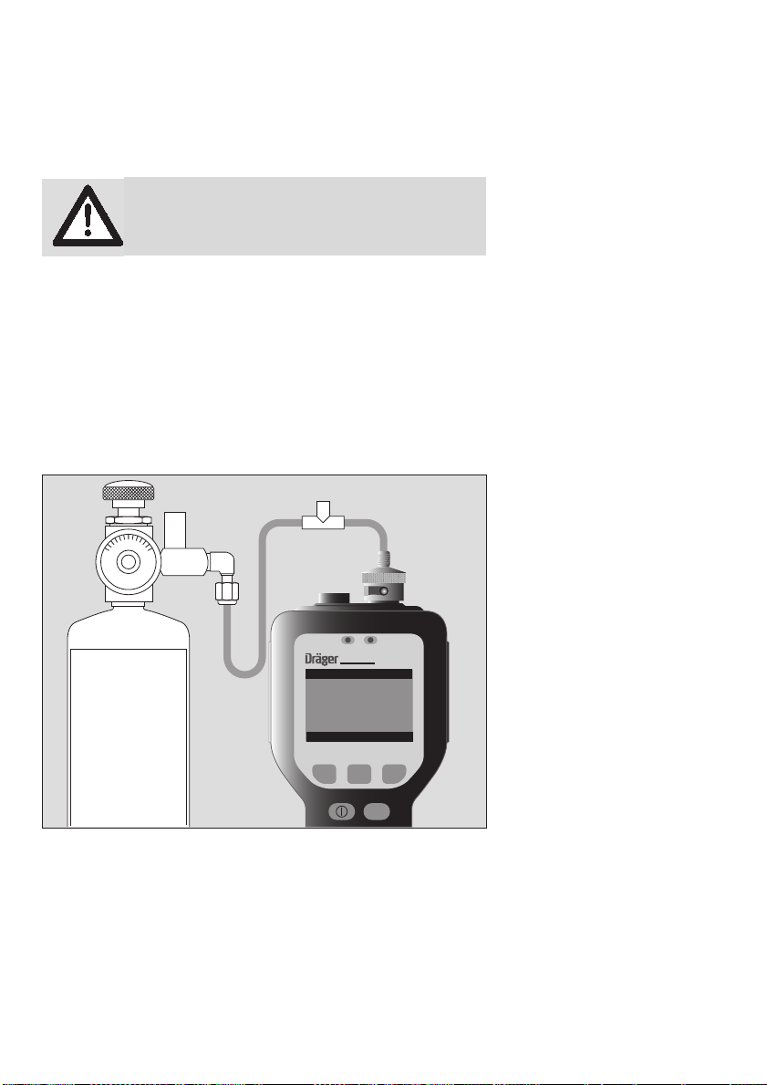
Routine Maintenance
Calibration Using the Flow-Match Regulator
Connecting the Flow-Match Regulator to the Cylinder
WARNING:
Observe proper handling procedure for all gases!
To connect the flow-match regulator to the gas cylinder:
1. Connect the regulator to the calibration gas cylinder.
2. If you are using a portable tank of calibration gas (Part No.
68 10 687), connect the regulator (Part No. 68 10 688) directly to
the tank.
3. When the regulator is connected properly, you can read the cylinder contents from the regulator gauge.
4. Connect the adapter tubing to the regulator.
5. Check if the Multi-PID 2 is sucking in the gas pressure free, e.g.
by means of a T-piece; paying attention the fact that the flow from
the gas cylinder is higher than the inlet flow of the Multi-PID 2.
Figure 18 – Calibration with Flow-Math
76
ALARM CHARGE
Multi-PID 2
Calibration
Calibration gas
concentration
100.0
cancel new next
CAL
01623958_01_en.eps
Page 77

Calibrating the Multi-PID 2 with the Flow-Match Regulator
1. Ensure that the short sample probe is connected to the MultiPID 2 inlet. If you are using the long probe for sampling, then ensure the long probe is connected to the Multi-PID 2.
NOTE:
Ensure the sample probe is free of any contamination, as this
will affect the calibration.
Routine Maintenance
2. Press the -key for approx. 2 seconds.
CAL
3. Follow the instructions on the display and either connect the MultiPID 2 to zero air, connect the optional activated charcoal filter
(Part No. CH 24 101) and filter tube holder (Part No. 83 19 093),
or leave the instrument unconnected so it can sample clean ambient air. Then press the “ next ” key. The Multi-PID 2 will take 60-90
seconds to set the zero point for calibration.
4. The Multi-PID 2 display will show » Zero air calibrated. Continue
calibration? « Press the “ next ” key.
5. Enter the span gas concentration if the concentration displayed on
the Multi-PID 2 is different than the concentration of the span gas
cylinder. Press the " new " key and follow the display prompts. For
further information, see page 36 for numeric value, duration, time,
and date entry. If the span concentration matches the span gas cylinder concentration, press the “ next ” key. To exit calibration,
press the “ cancel ” key.
6. Ensure the calibration gas cylinder is upright and open the regulator by turning the valve counter clockwise. Open the regulator until
the ball is 1/8” from its rest position.
7. Connect the span gas to the Multi-PID 2 (if the zero air calibration
was done with either a Zero Air cylinder or the optional activated
charcoal tube and tube holder, either should be disconnected before connecting the span gas fitting to the Multi-PID 2).
8. The Multi-PID 2 will take 60-90 seconds to set the span set point.
When finished with the calibration, the Multi-PID 2 will display
» Calibration complete! «.
NOTE:
If you are not using the Dräger Safety Flow-Match Regulator,
ensure that the inlet pressure is less than 0.35 bar (5 psi) when
calibrating.
NOTE:
While the Cal status is active, all alarms are deactivated.
77
Page 78

Routine Maintenance
Battery Charging
A fully charged battery pack powers the Multi-PID 2 for approximately
5,5 hours. If the instrument is to be used for more than 5,5 hours,
carry a spare battery pack (Part No. 83 23 622 or 83 17 670). When
the first one has been discharged, replace it with the spare.
NOTE:
If you do not turn the Multi-PID 2 off before removing the battery
pack, you will reset the instrument and you will lose all logged
data and setup parameters.
When the Multi-PID 2 displays the low battery symbol, the battery
pack requires charging. When the low battery symbol is displayed,
you have 30 minutes of operation left. The Multi-PID 2 will turn itself
off before the battery pack becomes critically low.
WARNING:
Do not remove or recharge the battery pack in a
hazardous location.
Upon return from field work, charge the battery packs as outlined in
Battery Charging on page 26. Use only the AC adapter specified for
use with the Multi-PID 2. Optionally you can use the off-line charger to
charge the battery pack independently of the instrument. See OffLine Charger on page 50.
NOTE:
You must use the 220 V battery charger (Part No. 83 17 661) in
order to comply with the requirements of the applicable Council
Directives.
If you do not require portable operation, you can use the Multi-PID 2
while it is connected to the AC adapter.
WARNING:
The Multi-PID 2 is not intrinsically safe when connected to an AC adapter.
When the Charge LED on the top of the Multi-PID 2 is red, the battery
is charging. When the Charge LED turns green, the battery is fully
charged.
78
Page 79

Battery Pack Care
Leaving the Multi-PID 2 for more than 3 months without charging the
batteries may result in the loss of recorded data and setup parameters. If the Multi-PID 2 is not used for long periods of time, recharge
the battery for a few hours every 30 days to avoid loss of data. See
Battery Charging on page 26 for instructions on charging the battery.
Please observe the following:
● For replacement battery pack use only Part No. 83 23 622 or
83 17 670.
WARNING:
Do not dispose of the battery pack in a fire. The cell
may explode!
● This battery pack must be disposed of properly. Check with local
codes for special disposal instructions.
● Do not open or mutilate the battery pack.
WARNING:
Exercise care in handling battery packs in order not
to short the terminals with conducting materials
such as rings, bracelets and keys. The battery or
conductor may overheat and cause burns.
● Charge the battery pack using the AC adapter provided with or
identified for use with this product only in accordance with the instructions and limitations specified in this manual. For AC adapter
use only Part No. 64 05 428 (North America) or Part No.
83 17 661 (Europe).
Routine Maintenance
79
Page 80

Routine Maintenance
Maintenance of the UV Lamp
Removing and Replacing the UV Lamp
WARNING:
Do not remove or replace the UV lamp in a hazardous location, danger of an explosion!
To remove the UV lamp from your instrument:
1. Ensure the instrument is turned off.
WARNING:
You must turn the instrument off before removing
the lamp cover.
2. Remove the lamp housing cover.
3. Tilt the Multi-PID 2 slightly and remove the UV lamp.
WARNING:
Do not touch the wire grid inside the detector cell.
Any dust or dirt in the detector cell can be blown out
with a gentle jet of compressed air.
Do not insert any object, other than the UV lamp,
into the lamp holder.
4. Without touching the lamp window, place the new lamp into the
Multi-PID 2 lamp holder, window first. See Figure 19.
80
Page 81

ALARM CHARGE
Figure 19 – Removing the UV Lamp
Multi-PID 2
Routine Maintenance
01823957_01_de.eps
NOTE:
Do not force the lamp into the lamp holder.
5. Replace the lamp housing cover. Tighten the cover down. Do not
over tighten.
6. Calibrate the Multi-PID 2 and then continue normal operation.
81
Page 82

Routine Maintenance
Cleaning the UV Lamp Window
During the course of normal operation, a film builds up on the window
of the UV lamp. The rate at which the film develops depends on the
type and concentration of the gases and vapors being sampled and
results from the UV light interacting with them.
Hot gases and vapors may contribute to a decrease in sensitivity
because they may condense on the lamp window. Condensation may
eventually evaporate off the window, but it will usually leave a residue
that must be removed by cleaning the lamp window.
Since some UV inhibiting deposits are invisible to the eye, regular cleaning of the lamp window is strongly recommended. Clean the lamp
frequently to prevent a heavy buildup of deposits that may be difficult
to remove.
WARNING:
Do not remove the UV lamp in a hazardous location.
The UV lamp cleaning kit (Part No. 83 18 318) includes aluminum
oxide powder (3.0-micron powder) and cotton swabs. Additionally,
you will require approximately 10 mL of methanol. When ordering
methanol, specify purge and trap grade.
The instructions provided below are for 10.6 eV lamps. Refer to Cleaning the Lithium Fluoride Window for special instructions to clean
the 11.7 eV lamp window.
82
WARNING:
Never touch the UV lamp window with your fingers.
Page 83

To clean the UV lamp:
1. Remove the lamp as outlined in Removing and Replacing the UV
Lamp on page 80.
2. Allow the lamp to cool to room temperature to avoid thermal
shock, which could crack the window.
3. Dampen a cotton swab in methanol and dab it into the cleaning
compound. Allow a small amount of the cleaning compound to adhere to the cotton tip.
WARNING:
Do not use methanol to clean the 11.7 eV lamp window.
4. Using small circular motions, rub the cleaning compound onto the
lamp window. Do not exert excessive force onto the window, since
the window can be permanently damaged by misuse.
5. Continue cleaning for approximately one minute.
6. Dampen a new cotton swab with methanol and remove any trace
amounts of the cleaning compound from the lamp window.
7. Wipe the window and the lamp with a dry, lint free tissue to remove
any trace amounts of the cleaning compound and methanol. All traces of cleaning compound must be removed.
8. If you removed an O-ring from the lamp, replace it now. Ensure
your hands are clean and dry.
9. Without touching the lamp window, replace the lamp as outlined
in Removing and Replacing the UV Lamp on page 80.
Routine Maintenance
Cleaning the Lithium Fluoride Window
To clean the 11.7 eV lamp window:
1. Clean the lamp window with dry aluminum oxide powder on a dry
cotton swab. Do not use methanol or water.
2. Wipe the window and the lamp with a dry, lint free tissue to remove
any trace amounts of the cleaning compound and methanol. All traces of cleaning compound must be removed.
3. The lamp window can also be regenerated by storing the lamp in
a desiccant for at least 5 days.
NOTE:
You may not be able to fully clean the 11.7 eV lamp window.
83
Page 84

Routine Maintenance
Replacing the Sample Inlet Filter
The Multi-PID 2 is equipped with a combined dust and water filter to
reduce detector contamination. As the filter collects dust, the MultiPID 2’s inlet flow rate and sensitivity decrease. The filter will not allow
water to pass through, but the filter will not stop all solvents.
NOTE:
Do not aspirate liquid samples with the Multi-PID 2!
Replace the filter on a weekly basis, or more frequently if the MultiPID 2 is used in a dusty or wet environment. You must replace the filter if the Multi-PID 2 has been exposed to water. If you are sampling
hot gases or vapors, condensation in the sample line may also affect
the filter.
WARNING:
Do not replace the inlet filter in a hazardous location.
To replace the inlet filter:
1. Turn the instrument off. Unscrew the filter housing from the detector housing. Be careful not to lose the O-ring seal.
2. Remove the Teflon/Polypropylene filter and install the new filter
(Part No. 83 17 681). Place the filter so that the Teflon side is facing down in the filter housing and the mesh side is facing the Multi-PID 2.
Handle the filter disk only by the edges. The mesh may be damaged or contaminated by excessive handling. Use forceps if possible.
3. Replace the filter housing.
4. Recalibrate and then continue normal operation.
84
Page 85

ALARM CHARGE
Figure 20 – Replacing the Inlet Filter
Routine Maintenance
Multi-PID 2
01923957_01_de.eps
Waste electrical and electronic equipment
EU-wide regulations for the disposal of electric and electronic
appliances which have been defined in the EU Directive 2002/96/
EC and in national laws are effective from August 2005 and apply to
this device.
Common household appliances can be disposed of using special collecting and recycling facilities. However, as this device has not been
registered for household usage, it must not be disposed of through
these means. The device can be returned to your national
Dräger Safety Sales Organization for disposal. Please do not hesitate
to contact the above if you have any further questions on this issue.
85
Page 86

Routine Maintenance
86
Page 87

Troubleshooting
Troubleshooting
87
Page 88

Troubleshooting
General Information
If you have a service-related question about the Multi-PID 2, consult
this manual first. If you cannot find the answer in this documentation,
contact Dräger Safety’s Technical Support Department.
When you call, please have the following information ready:
1. A description of what happened and what you were doing when
the problem occurred.
2. Any corrective action that you have tried.
3. The exact wording of any messages that appeared on the display.
WARNING:
Do not service the Multi-PID 2 in a hazardous location.
88
Page 89

Troubleshooting
Situation Cause Action
Zero Air Error Contamination of sample
lines, sample probe, inlet filter or fittings before the
detector
Span gas and zero air are
mixed up.
Ambient air is contaminated. If you are not sure of the cleanliness
Span Gas Error Span gas and zero air are
mixed up.
Span gas concentration is
too low.
UV lamp window is dirty. Clean the lamp window.
Clean or replace contaminated item
Ensure that clean air is used to zero
the Multi-PID 2s.
of the ambient air, use a commercial
zero grade air to zero the Multi-PID 2.
Ensure that clean air is used to zero
the Multi-PID 2.
Span gas concentration should be
higher than 25 ppm.
See page 82.
Troubleshooting
UV lamp is failing. Install a new lamp. See Removing
The concentration and sample gas are not com-patible
with the Multi_PID 2.
UV Lamp Error UV lamp has not started
immediately.
UV lamp is not installed Install UV lamp. See Removing and
Incorrect lamp is installed. Use only a getterless UV lamp.
Electronic problem Contact Dräger Safety for assistance.
and Replacing the UV Lamp on page
80.
Contact Dräger Safety.
This fault may occur momentarily
when the Multi-PID 2 is first turned
on. Allow 60 seconds for UV lamp to
start and fault to clear.
Turn the Multi-PID 2 off then on
again. Wait 60 seconds for UV lamp
to start.
Replacing the UV Lamp on page 80
83 18 307 or 83 18 317.
89
Page 90

Troubleshooting
Situation Cause Action
Pump Error If the pump sounds labored,
the pump is operating out-
Check for obstructions in the sample
line.
side its normal operating
range.
Verify that the sample line, sample
probe and inlet filter are not blocked.
Ensure that the sample outlet is not
blocked.
The Multi-PID 2 has aspirated
Contact Dräger Safety.
a liquid.
The pump has failed.
Contact Dräger Safety.
Blocked Filter Replace the inlet filter Dräger Safety
Part No. 83 17 681.
Instrument over
range
High concentrations of gases
will saturate the detector and
electronics.
The detector has become
saturated.
Wait until the display returns to nor-
mal. PIDs are designed to detect rela-
tively low levels of gases.
Move the Multi-PID 2 to a location
where it can sample clean air. Sample
clean air until the readings stabilize at
a low level.
Detector has been short-cir-
Contact Dräger Safety.
cuited by foreign matter in
the cell.
90
Page 91

General Questions
Fault Possible Cause Remedy
Very low or no instrument
response detected, yet compounds are known to be present
The Multi-PID 2 has not been
properl
Memory slots are not set up
correctly.
Response Factor has been
set to zero.
Detector is leaking. Ensure the UV lamp is cor-
UV lamp is the incorrect size. Contact Dräger Safety for
Sampling environment is
extremely humid or it is raining.
UV lamp is failing. Install a new UV lamp. See
High concentrations of nonionizable compounds.
Verify the concentration of
the span gas. Calibrate the
Multi-PID 2. See page 73.
Program the memory slots.
See page 67.
Set Response Factor to 1.0
or refer to Table 6 for correct
response factor.
rectly installed.
Ensure the lamp cover is
tight. Do not over tighten.
Ensure the O-ring seal on the
lamp cover is positioned correctly.
correct lamp.
Water vapor is not ionized by
the PID. Water vapor does
scatter and absorb light that
causes a higher or lower reading. The Multi-PID 2 has
been designed to work in a
humid environment but you
may notice a decreased
response.
page 80.
Chemical compounds with
an ionization potential higher
than 10.6 eV or 11.7 eV scatter and absorb UV light. Sensitivity may be decreased.
Contact Dräger Safety for
more information.
Troubleshooting
91
Page 92

Troubleshooting
Fault Possible Cause Remedy
Erroneous high readings Sampling environment is very
humid.
Water vapor may contain
mineral salts which carry a
charge. The water vapor
becomes an electrolytic solution which becomes ionized
when it enters the detector.
The Multi-PID 2 is not properly calibrated.
Ensure that the calibration
gas is the correct concentration and calibrate the MultiPID 2 as described on page
74.
Memory Slots have not been
properly programmed.
Detector has been short-cir-
Program the memory slots.
See page 67.
Contact Dräger Safety.
cuited by foreign material.
Date and time setting are not
retained
The battery pack was removed before the Multi-PID 2
was turned off.
The Multi-PID 2 has not been
used for 3 months or more.
Replace the battery pack and
reset the time and date. See
page 26.
Connect the Multi-PID 2 to
the battery charger and
recharge the battery. Reset
the date and time.
Display is blank Battery pack is critically low. Recharge or replace the bat-
tery pack.
Sample flow is less than 300
ml/min/
The battery pack is not connected to the Multi-PID 2 properly.
Inlet filter is plugged. Replace the inlet filter. See
Inlet filter is incorrectly installed.
Ensure the battery pack connector is securely attached to
the Multi-PID 2.
page 84.
Ensure the inlet filter is instal-
led correctly. See page 84.
Sample outlet is blocked. Clear blockage from sample
outlet.
Pump has been damaged. Contact Dräger Safety.
Liquid has been aspirated. The Multi-PID 2 has been
Contact Dräger Safety.
exposed to a solvent that can
pass through the inlet filter.
Very corrosive gases have
Contact Dräger Safety.
been sampled.
Cannot download data or
communicate with PC.
Cable is not connected Connect the Multi-PID 2 to
the PC. See page 24.
92
Page 93

Appendices
Appendices
93
Page 94

Appendices
Specification
Size: 9” (230 mm) long x 3” (80 mm) deep
x 4.25” (110 mm) wide at display tapering
to 2.6” (67 mm) at handle
Weight: 1.9 pounds (0.86 kg)
Detector: Instant on photoionization detector with
standard 10.6eV UV lamp, optional 11.7 eV
lamp available
Keypad: 5 keys with tactile feedback
Display: 8 line LCD display for alphanumeric rea-
douts and soft key display
Datalogger memory: 200 hours at 1 minute interval
Serial output: RS-232, 9600 baud, 8 data bits with no
parity, for connection to a Windows
patible computer
Audio output: 85 decibels on Alarm
Inlet connection: 1/8” (3.175 mm) fitting
Battery type: 83 17 670: Nickel cadmium rechargeable
cell with intelligent charger. The battery
pack is 24% cadmium (Cd) by weight.
83 23 622: NiMH rechargeable cell with
intelligent charger. The battery pack con-
tains no cadmium (Cd).
Charge/discharge time: 4 hr/6 hr
Input Power: 12 VDC, 1.0 A
Battery charger: Automatically charges and maintains full
charge in battery pack.
U.S. and Canada – Part No. 64 05 428
Input 120 VAC, 60 Hz, 21 W
Output +12 VDC 1000 mA
Regulatory Approvals: CSA, UL
All other Countries – Part No. 83 17 660
Input 100-250 VAC, 50-60 Hz, 0.5-0.3 A
Output +12 VDC 2.08 A
Regulatory Approvals: ATEX, UL
TM
com-
94
Page 95

Appendices
Materials in sample stream: Stainless steel, Teflon, Viton
®
, polypropy-
lene, nitrile-chorobutadiene rubber, nickel.
Inlet filter: Replaceable Teflon/Polypropylene, 1 μm
Inlet flow rate: Greater than 300 mL/min
o
Operating temperature range: 0 to 50
I/S Certified Temperature Range: 0 to 40
C (32 to 122 oF)
o
C (32 to 105 oF)
Operating humidity range: 0 to 95% relative humidity
(non-condensing)
Operating humidity range with optional
humidity pre-filter tube:
0 to 100% relative humidity
(non-condensing)
Operating altitude range: Up to 10,000 ft (3000 m)
o
Storage temperature range: –10 to 65
C (14 to 149 oF)
Storage humidity range: 0 to 100% relative humidity
(non-condensing)
Storage altitude range: Up to 15,000 ft (4570 m)
Operating concentration range: 0.1 to 2,000 ppm, isobutylene
Accuracy: +/–10% or +/–2 ppm, whichever is greater
Precision: 1% of calibration
(calibrated with 100 ppm isobutylene)
Response time: Less than 3 seconds to 90%
Detection limit: 0.1 ppm isobutylene
Dilution probe: Normal calibration: concentrations bet-
ween 100 to 20,000 ppm +/– 20%
High accuracy calibration: concentrations
between 100 to 1000 ppm +/– 15%.
Concentrations between 1000 to 20,000
ppm +/– 20%
NOTE:
Specifications subject to change without notice.
95
Page 96

Appendices
Installing Alternate AC Plug on the Battery Charger
In most cases the Multi-PID 2 will be shipped with an AC line cord
that will fit the AC wall outlet in your area. If this cannot be done, you
may need to obtain an AC line cord suitable for the AC receptacle in
your area.
The AC line cord, attached plug and receptacle must be marked with
your country’s certification mark and the cord must have a Harmonization (HAR) mark.
The line cord must be rated for either 100 to 120 VAC at 60 Hz or
220 to 240 VAC at 50 Hz. The voltage rating will depend on the
voltage in your area.
Contact your Dräger Safety representative to obtain more information.
Calibration Gas Supplier
The recommended span gas is isobutylene in air. 100 ppm isobutylene in air may be obtained from Dräger Safety.
The exact concentration will be determined by your application. Other
concentrations and other gases may be obtained from your local gas
supplier. If you cannot locate a local gas supplier, contact Dräger
Safety’s Technical Support Department.
96
Page 97

Presets and Response Factors
Presets simplify Memory Slot programming, and provide standard
response factors and alarm levels for approximately 100 compounds.
The name, response factor and three alarm levels are all set from the
preset.
You can change any of the values entered in the Memory Slots. Changes made to the library information that has been loaded into a Preset
will have no effect on the original library entry.
The response factors were determined over the range 5 - 500 ppm,
based on a 100-ppm isobutylene calibration. Isobutylene RF = 1.0.
The following formula is used for calculation of response factors:
Appendices
Response Factor =
Actual Concentration
Multi-PID 2 Response
A response factor less than 1.0 indicates a compound response better than that of isobutylene. A response factor greater than 1.0 indicates a lower response than that of isobutylene.
NOTE:
It does not matter which response factor is entered. The MultiPID 2’s response is not specific to any one compound. The displayed reading represents the total concentration of all ionizable compounds in the sample.
Table 5 – Response Factors
Compound Response Factor
Acetaldehyde 10.5
Acetone 1.2
Acetophenone 2.0
Acrolein (2-Propenal) 4.0
Acrylic Acid 10.9
Acrylonitrile ND
3)
Allyl Chloride (3-Chloro-1-Propene) 3.9
Benzene 0.5
Bromoform (Tribromomethane) 2.0
1,3-Butadiene 0.7
n-Butane 0.2
n-Butanol 3.4
97
Page 98

Appendices
Compound Response Factor
n-Butyl Acetate 2.3
Butyl Acrylate 1.8
Butyl Cellosolve 3.1
n-Butyl Acrylate 1.8
n-Butyl Mercaptan (Butanthiol) 0.6
Carbon Disulfide 1.3
Chlorobenzene 0.4
Crotonaldehyde (2-Butenal) 1.2
Cumene (Isopropylbenzene) 0.6
Cyclohexane 1.3
Cyclohexanol 3.4
Cyclohexanone 0.9
Diacetone alcohol 1.8
1,2-Dichlorobenzene (ortho-) 0.5
cis-1,2-Dichloroethylene 0.8
trans-1,2-Dichloroethylene 0.4
N,N-Dimethylformamide (DMF) 0.8
1,4-Dioxane 1.3
Epichlorohydrin 6.5
Ethanol 8.8
Ethyl Acetate 3.8
Ethyl Acrylate 2.3
Ethylbenzene 0.5
Ethyl Cellosolve (2-Ethoxyethanol) 1.3
Ethylene Glykol 0.1
Ethyl Ether (Diethyl Ether) 1.2
Ethyl Mercaptan (Ethanethiol) 0.6
Ethylene 10.1
n-Heptane 2.4
n-Hexane 4.7
2-Heptanone 2.1
Hydrogen Sulfide 3.3
98
Page 99

Compound Response Factor
Isoamyl Acetate 1.8
Isobutyl Acetate 2.6
Isobutyl Alcohol 0.3
Isobutyraldehyde 1.1
Isopentane 8.2
Isoprene (2-Methyl-1,3-Butadiene) 0.6
Isopropanol 4.4
Isopropyl Acetate 2.6
Isopropyl Ether 0.8
Mercaptopropionic Acid 0.1
Methacrylic Acid 000
4)
Methyl n-Amyl Ketone (2-heptanone) 2.1
Methyl Bromide (Bromomethane) 1.6
Methyl Chloroform (1,1,1 – TCA) 000
Methylene Chloride 000
4)
4)
Methyl Ethyl Ketone (2-Butanone) 0.8
Methyl Isobutyl Ketone 1.0
Methyl Mercaptan 0.5
Methyl Methacrylate 1.4
Methyl tert-Butyl Ether (MTBE) 0.8
Monomethylamine 1.3
n-Nonane 1.4
iso-Octane (2,2,4-Trimethylpentane) 1.2
n-Pentane 10.4
Polypropylene 0.8
Propane 000
4)
n-Propanol 5.1
Propionaldehyde (Propanal) 14.8
n-Propyl Acetate 3.1
Propylene 1.2
Propylene Oxide 5.8
Styrene 0.4
Appendices
99
Page 100

Appendices
Compound Response Factor
Syltherm XLT 9.8
Tetrachloroethylene (Perchloroethylene) 0.5
Tetrahydrofuran 1.5
Therminol 000
4)
Toluene 0.5
1,1,1 – Trichloroethane 000
Triethanolamine ND
4)
3)
Trichloroethylene (TCE) 0.5
Trimethylamine 0.9
1,2,4 – Trimethyl Benzene 2.3
1.3.5 – Trimethyl Benzen 1.7
Vinyl Acetate 1.2
Vinyl Bromide 0.4
Vinyl Chloride (Chloroethylene) 1.7
Vinylidene Chloride (1,1-DCE) 0.8
meta –Xylene 0.5
ortho –Xylene 0.5
para-Xylene 0.5
Table 6 – Library Entries
Compound Code RF
Acetaldehyde ACETAL 10.5
Acetone ACETONE 1.2
Acrolein (2-Propenal)
5)
Allyl Chloride (3-Chloro-1-Propene)
ACROLEIN 4.0
5)
ALLCHLOR 3.9
Benzene BENZENE 0.5
5)
Bromoform (Tribromomethane)
BROMFORM 2.0
1,3-Butadiene 13BUTADI 0.7
n-Butanol nBUTANOL 3.4
100
 Loading...