

Page 1

Wireless communication
ISA100 Wireless
TM
Technical Manual
Wireless communication
Page 2

This page has been left blank intentionally.
2 Technical Manual | Wireless communication
Page 3

Contents
TM
Wireless communicationISA100 Wireless
Contents
1 Introduction .............................................................................................. 5
1.1 Target group ................................................................................... 5
1.2 General safety statements.............................................................. 5
1.3 Meaning of the warning notes......................................................... 5
1.4 Typographical conventions............................................................. 5
1.5 Brand names .................................................................................. 6
2 Wireless data transmission in industrial settings................................. 7
3 ISA100 Wireless
TM
basics ....................................................................... 9
3.1 Network components and participants............................................ 10
3.1.1 System manager .............................................................. 11
3.1.2 Backbone.......................................................................... 11
3.1.3 Access points (AP) ........................................................... 11
3.1.4 Field devices..................................................................... 12
3.1.5 Hop points ........................................................................ 13
3.2 Network topologies ......................................................................... 14
3.2.1 Star topology .................................................................... 14
3.2.2 Mesh topology .................................................................. 15
3.2.3 Comparison of star topology and mesh topology ............. 16
3.3 Network performance and network configuration ........................... 16
3.3.1 Signal quality .................................................................... 16
3.3.2 Network coverage............................................................. 18
3.3.3 Sub-networks.................................................................... 19
3.3.4 Sky mesh.......................................................................... 20
3.3.5 Network configuration with retrofitted field devices .......... 20
3.3.6 Network configuration for small networks......................... 21
3.3.7 Network configuration with long backbone lines............... 22
3.3.8 Network configuration with a 4–20 mA control unit .......... 24
4 ISA100 Wireless
TM
data transmission basics........................................ 25
4.1 Frequency band and bandwidth ..................................................... 25
4.2 Data integrity................................................................................... 26
4.2.1 Frequency hopping........................................................... 26
4.2.2 Hopping patterns .............................................................. 26
4.2.3 Standard hopping pattern................................................. 27
4.2.4 Duo-Cast .......................................................................... 28
4.2.5 Time-Division-Multiple-Access (TDMA)............................ 28
4.2.6 Clear channel assessment (CCA) .................................... 28
4.2.7 Automatic-Repeat-reQuest (ARQ).................................... 28
4.2.8 Blacklisting........................................................................ 29
4.2.9 Adaptive hopping.............................................................. 29
4.2.10 Path diversity .................................................................... 29
4.2.11 Types of routing ................................................................30
4.3 Data structure ................................................................................. 30
4.3.1 Data fields......................................................................... 31
4.3.2 User application process (UAP) ....................................... 32
4.3.3 Object identifiers............................................................... 33
Technical Manual | Wireless communication 3
Page 4

Contents
4.3.4 Attribute classes ............................................................... 34
4.3.5 Data format (without PROFIsafe
®
communication).......... 35
4.4 Traffic.............................................................................................. 35
4.4.1 Data query ........................................................................ 36
4.4.2 Sampling rate and stale limit ............................................ 36
4.4.3 Network and energy management with ISA100 wireless
communication ................................................................. 38
4.4.4 Device performance information....................................... 39
5 Transmission basics for PROFIsafe
5.1 Black channel principle ................................................................... 40
5.2 Data integrity for PROFIsafe
5.2.1 PROFIsafe
®
network constraints...................................... 42
®
communication ......................... 40
®
communication ............................... 41
5.3 Data structure ................................................................................. 42
5.3.1 Data fields......................................................................... 42
5.3.2 Data format for PROFIsafe
5.4 Traffic for PROFIsafe
®
communication .......................................... 43
®
communication ................... 43
6 Network integration (provisioning) of gas warning devices................ 45
6.1 Network integration parameters...................................................... 45
6.1.1 Modbus parameters.......................................................... 45
6.1.2 PROFIsafe
®
traffic............................................................ 45
6.2 Out Of Band Provisioning (OOB, Yokogawa gateway only)........... 46
6.3 Over the air provisioning (OTA)...................................................... 48
7 Troubleshooting....................................................................................... 49
7.1 Errors during network integration.................................................... 49
7.2 Errors during operation ................................................................... 49
7.2.1 Status byte of a transmitted value .................................... 49
7.2.2 DIAG_STATUS attribute byte........................................... 51
8 Recommended network components..................................................... 53
8.1 Network components recommended without restrictions ............... 53
8.1.1 System manager .............................................................. 53
8.1.2 Access points ................................................................... 53
8.1.3 Other components............................................................ 53
8.2 Network components recommended with restrictions .................... 53
8.2.1 System manager .............................................................. 53
9 Glossary.................................................................................................... 54
9.1 Glossary on parameter and object names...................................... 55
4 Technical Manual | Wireless communication
Page 5

1 Introduction
This document supplements the instructions for use for gas warning devices:
– Dräger Polytron
– GasSecure GS01 / GasSecure GS01-EA
– Polytron Repeater ISA100
– Polytron 6700 IR WL
This document contains additional information on the ISA100 Wireless
1.1 Target group
This document is intended for technicians with training in PLC programming,
trained electricians or persons who have received instruction from a trained
electrician. These persons must also be familiar with the applicable standards.
1.2 General safety statements
Before using this product, carefully read the associated instructions for use. This
document does not replace the instructions for use.
®
6100 EC WL
Introduction
TM
interface.
1.3 Meaning of the warning notes
The following warning notes are used in this document to notify users of possible
dangers. The meanings of the warning notes are defined as follows:
Alert icon Signal word Consequences in case of nonob-
servance
WARNING Indicates a potentially hazardous situation
which, if not avoided, could result in death
or serious injury.
CAUTION Indicates a potentially hazardous situation
which, if not avoided, could result in injury.
It may also be used to alert against unsafe
practices.
NOTICE Indicates a potentially hazardous situation
which, if not avoided, could result in damage to the product or environment.
1.4 Typographical conventions
Text Text marked in bold denotes labeling on the device and on-screen
messages.
► This triangle labels possible methods of avoiding the hazards men-
tioned in warning notices.
> The greater-than sign denotes the navigational path in a menu.
This symbol denotes information that make using the product easier.
Technical Manual | Wireless communication 5
Page 6

Introduction
1.5 Brand names
–HART® is a registered trademark of the HART Communication Foundation.
–PROFIBUS
e. V.
– FOUNDATION
– ISA100 Wireless
Automation (ISA).
– Bluetooth
– WirelessHART
Communication Foundation.
–PROFIsafe
®
is a registered trademark of the PROFIBUS Nutzerorganisation
TM
®
is a registered trademark of Bluetooth SIG, Inc.
®
®
is a registered trademark of Siemens Aktiengesellschaft.
is a registered trademark of the Fieldbus Foundation.
TM
is a registered trademark of the International Society of
(WHART) is a registered trademark of the HART
6 Technical Manual | Wireless communication
Page 7
Wireless data transmission in industrial settings
2
3
1
P6 P6
2 Wireless data transmission in industrial settings
There are a number of different protocols and types of network for wireless data
transmission, which will be described in this manual in conjunction with Dräger
products. The following diagram shows the application areas for various protocols.
Other protocols (WPAN, for example) are not considered in this context.
40934
Fig. 1 Wireless data transmission protocols
1WFAN
2WLAN
3
Bluetooth
®
or infrared
WLAN and WFAN
In a WFAN (Wireless Field (or Factory) Area Network), industrial field devices
communicate with one another or with a control center. The control center controls
and monitors the field devices. When communicating via WFAN, protocols such as
ISA100 Wireless
TM
and WirelessHART® (WHART) are used.
WLAN (Wireless Local Area Network) is a local, usually private wireless network.
The WLAN infrastructure of an industrial plant is used for mobile end devices and
video transmission (stationary cameras).
Technical Manual | Wireless communication 7
Page 8

Wireless data transmission in industrial settings
Main application areas
There are 3 main areas of application for wireless networks:
– Plant safety
Transmitters monitor safety-critical areas and send wireless measured values.
ISA100 Wireless
TM
allows for SIL 2-compliant failsafe communication through
the transport of PROFIsafe
– Monitoring field devices
The status of field devices is monitored (e.g. temperature, sensor status of a gas
warning device).
– Process monitoring and process control
Wireless data transmission allows for detailed process monitoring and process
control without expensive cable routing costs.
These areas of application must be able to tolerate latencies of 100 ms.
Advantages of a wireless network
Wireless networks offer many advantages compared to wired networks.
– Wireless networks can be made operational more quickly and installing the
infrastructure creates less costs.
– Wireless networks can be expanded with greater ease and at less cost. Adding
new field devices and putting them into operation, as well as removing them, is
easier.
– The parameters of field devices as well as diagnostics and maintenance can be
configured centrally.
– Errors do not occur when wiring field devices (e.g. cable break, wiring problems
in the field device).
– Wireless networks can be employed in places a wired network would be
impossible, expensive, or difficult to implement (e.g. on rotating platforms).
– Temporary installations that are dismantled after a certain time also profit from
wireless networking. Temporary installations no longer need arduous and
expensive cabling.
®
messages.
Furthermore, a wired network’s infrastructure can be expanded wirelessly (creating
redundancy).
8 Technical Manual | Wireless communication
Page 9

3 ISA100 WirelessTM basics
ISA100.11a is a wireless networking protocol internationally recognized as IEC
Standard 62734 and developed by the International Society of Automation (ISA). It
is based on the ISO/OSI reference model and allows for reliable, secure data
transmission for control- and regulation-related applications, process monitoring
and alerts.
ISA100 Wireless
data transmission even over long distances with low power consumption.
As with most fieldbus systems, a ISA100 Wireless
any field devices required due to standardization. All field devices in the network
can interact with one another independent of manufacturer.
ISA100 Wireless
system management, gateway requirements and security specifications.
Failsafe communication
ISA100 Wireless
between controller and field device. This secure data transfer method is performed
via tunneling. Tunneling facilitates the use of different communication protocols via
the ISA100 Wireless
PROFIsafe
outside the ISA100 Wireless
TM
is comparable to a fieldbus system in that it allows for reliable
TM
defines basic functions and requirements for field devices,
TM
allows for failsafe communication (e.g. SIL 2-compliant)
TM
®
communication protocol. This communication protocol is transmitted
infrastructure. Failsafe communication is done via the
TM
infrastructure via PROFINET.
ISA100 WirelessTM basics
TM
network can be expanded with
Advantages of ISA100 Wireless
TM
There are different wireless network protocols. Among others, the ISA100
Wireless
– Transfer of other communication standards (e.g. PROFIsafe
TM
protocol has the following advantages over other protocols:
®
, HART®)
– Bandwidth for safety-relevant data can be reserved. This reserved bandwidth
ensures the rapid transmission of safety-relevant data at any time to the control
center. The transmission of safety-relevant data is not affected by other data
traffic.
– Response times of a ISA100 Wireless
TM
network are variable and shorter than
those of other protocols.
Technical Manual | Wireless communication 9
Page 10

ISA100 WirelessTM basics
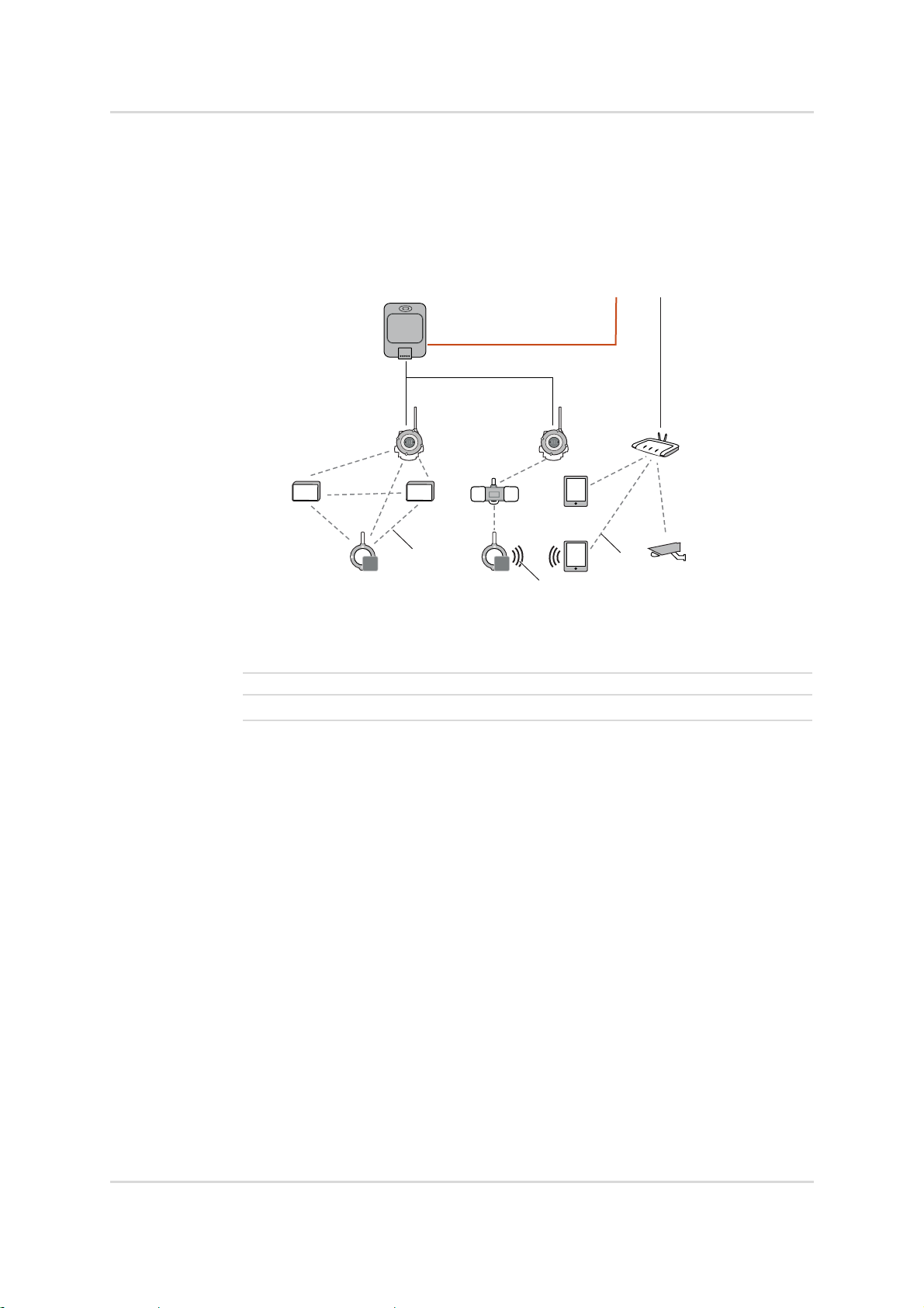
3.1 Network components and participants
4
18
5
6
7
6
10
14
15
16
13
11
12
P6
Fig. 2 Example topology of a wireless network
3
5
P6
8
1
9
17
38243
2
1 Control center
2 Control unit for wired field devices
3 Control unit
4 System manager
5 Access point in the function as a backbone router
6 Access point
7 Access point in the function as a field device access point
8Hop point
9 Retrofitted field device
10 I/O field device
11 GasSecure GS01
12
Dräger Polytron
®
6100 EC WL
13 Backbone
14 Ethernet or fiber-optics
15 Wireless data transmission from an access point to the backbone
16 Wireless data transmission between field devices and to the backbone
17 Wired analog or digital communication
18
Wired Modbus communication or PROFIsafe
®
communication via PROFI-
BUS/PROFINET
10 Technical Manual | Wireless communication
Page 11

3.1.1 System manager
The system manager monitors and manages the following system functions,
among others:
– Security management
– System performance, system latencies, redundancy
– System time
– Field device management (e.g. address allocation and routing tables)
Wireless gateway and system manager are the same thing for the purposes of this
manual. In detailed descriptions, system managers and gateways must be
considered separately from one another.
Controllers are connected to the system manager (e.g. Dräger REGARD
with Modbus Master module). Control units process the system manager’s data and
trigger alerts or countermeasures.
If PROFIsafe
F-host (failsafe host) must be used as a controller , which communicates with Fslaves (FailSafe field devices). In this case, the system manager only forwards the
messages and does not interfere with PROFIsafe
®
is used for communication purposes (e.g. for SIL 2 applications), an
ISA100 WirelessTM basics
®
communication.
®
7000
3.1.2 Backbone
The backbone is the wired part of the network, which connects the backbone router
(BBR) to the system manager. The connection is established via fiber-optic cable
(FOC) or Ethernet.
3.1.3 Access points (AP)
An access point is the transition from the wireless to the wired parts of the network.
Access points transmit the information from their end devices via cable to the
system manager. APs can be compared to the base station of a mobile landline
phone. In both cases, a wireless network is established for a multitude of mobile
end devices.
An AP performs different roles depending on the position in which it is located in the
network.
3.1.3.1 Backbone router (BBR)
If an access point is wired directly to the backbone, the access point is referred to
as the backbone router. Several backbone routers can be connected to the
backbone.
Field devices and field device access points communicate wirelessly with the
backbone router via the sub-network, which is established by the backbone router.
Technical Manual | Wireless communication 11
Page 12

ISA100 WirelessTM basics
Additional access points can be wired to the backbone router.
Risk of confusion
Backbone routers are connected to the backbone via cables. Repeaters or field
devices with routing functionalities are often also referred to as routers. However,
these "routers" are not connected to the backbone via cables and only forward the
signals.
Backbone routers as part of the system manager
Backbone routers can also be part of the system manager.
3.1.3.2 Field device access points (FDAP)
Field device access points are access points that communicate wirelessly with the
backbone. Communication to the backbone is done either via access points or
directly over the backbone router.
Dräger-approved devices are listed in the appendix.
3.1.4 Field devices
Field devices may also be called terminal devices or clients. They log on to the AP
and exchange information. Field devices are also called I/O devices because they
receive (input) and send (output) data.
There are field devices that communicate with the control center via cable in
addition to communicating wirelessly. These field devices are retrofitted with an
ISA100 Wireless
TM
antenna. They additionally communicate via wire with another
interface (a 4–20 mA interface, for example).
Field devices can be mobile field devices (tablets, smartphones, laptops), stationary
field devices or slow-moving stationary field devices. Mobile field devices often
communicate with an additional system manager or gateway via a different protocol
(non-ISA100 Wireless
TM
Due to their being integral elements of the network infrastructure, access points or
field device access points are not called field devices.
3.1.4.1 Routing functionalities
Some field devices can also act as a router in addition to their normal functionality.
Field devices with this function activated create hop points in the network.
These devices are often connected to a power line due to the extra energy
requirements involved in router operation.
Field devices with routing functionalities are also available without measuring
functions. They are then only integrated into the network as routers. The Polytron
Repeater ISA100 is a router without measuring function.
).
®
12 Technical Manual | Wireless communication
Page 13
3.1.4.2 Power supply
P6 P6
P6
1
1
2
ISA100 WirelessTM basics
Power is supplied to field devices via batteries or the power grid. ISA100
Wireless
TM
allows for every type of power supply.
If battery operation is not possible, field devices are connected to an external power
supply. An external power supply may be necessary if the routing functionality is
active and there is a lot of wireless communication.
When operating in explosion-hazard areas, an upstream safety barrier must be
installed for external power supplies.
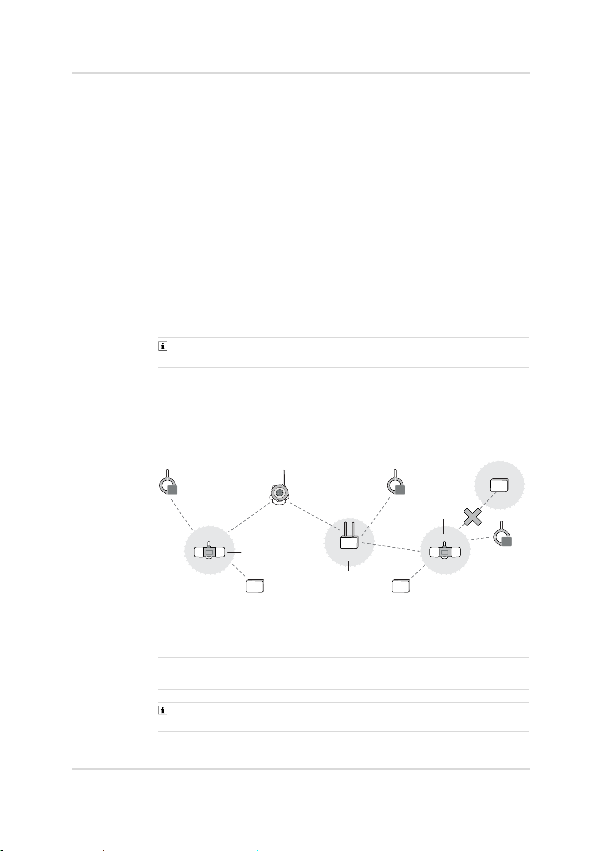
3.1.5 Hop points
Routers or field devices with a router function form a hop point in the sub-network.
Hop points expand a network and ensure redundant transmission routes. Signals
are forwarded without processing and no separate sub-network is established.
Data transmissions via hop points to the system manager are slower than direct
data transmissions to access points. Latencies (wait times) at the hop points can
delay communication.
The communication paths via hop points are prevented ex-factory for some
system managers. But, the function can be activated.
Restrictions for installations with short response times
Series-connected hop points can delay the response time. If response times are a
critical factor, there must be a limited number of hops (wireless interfaces) from the
field device to the access point. Fig. 3 shows a sub-network with only one (1) or two
(2) hops allowed.
Fig. 3 Hop points in a sub-network
1 First hop point after the sub-network access point
One further hop point is possible.
2 Second hop point after the sub-network access point
Another hop point could cause too much of a delay in the response time.
System managers from Yokogawa support a maximum of 4 hops (wireless
interfaces) between a field device and the backbone router (as at September 2020).
38255
Technical Manual | Wireless communication 13
Page 14
ISA100 WirelessTM basics
1 2
3.1.5.1 Routers
Routers are also called repeaters. Routers increase the size of the network and
cancel out weak spots. They form a hop point in the sub-network. Incoming data is
forwarded without processing.
Routers do not establish their own sub-networks.
3.2 Network topologies
There are 3 network topologies for ISA100 networks.
– Star topology
– Mesh topology
– Partial mesh topology
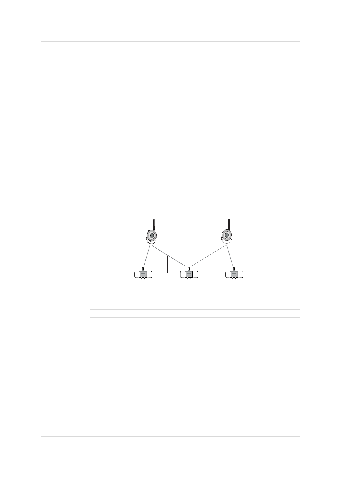
3.2.1 Star topology
In a star topology, field devices communicate with one or more access points. The
field devices can only exchange information via access points, not directly with one
another. Multiple access points are often employed to make the network more failsafe.
Fig. 4 Star topology and communication channels
1 Primary communication channel
2 Secondary communication channel
40935
14 Technical Manual | Wireless communication
Page 15
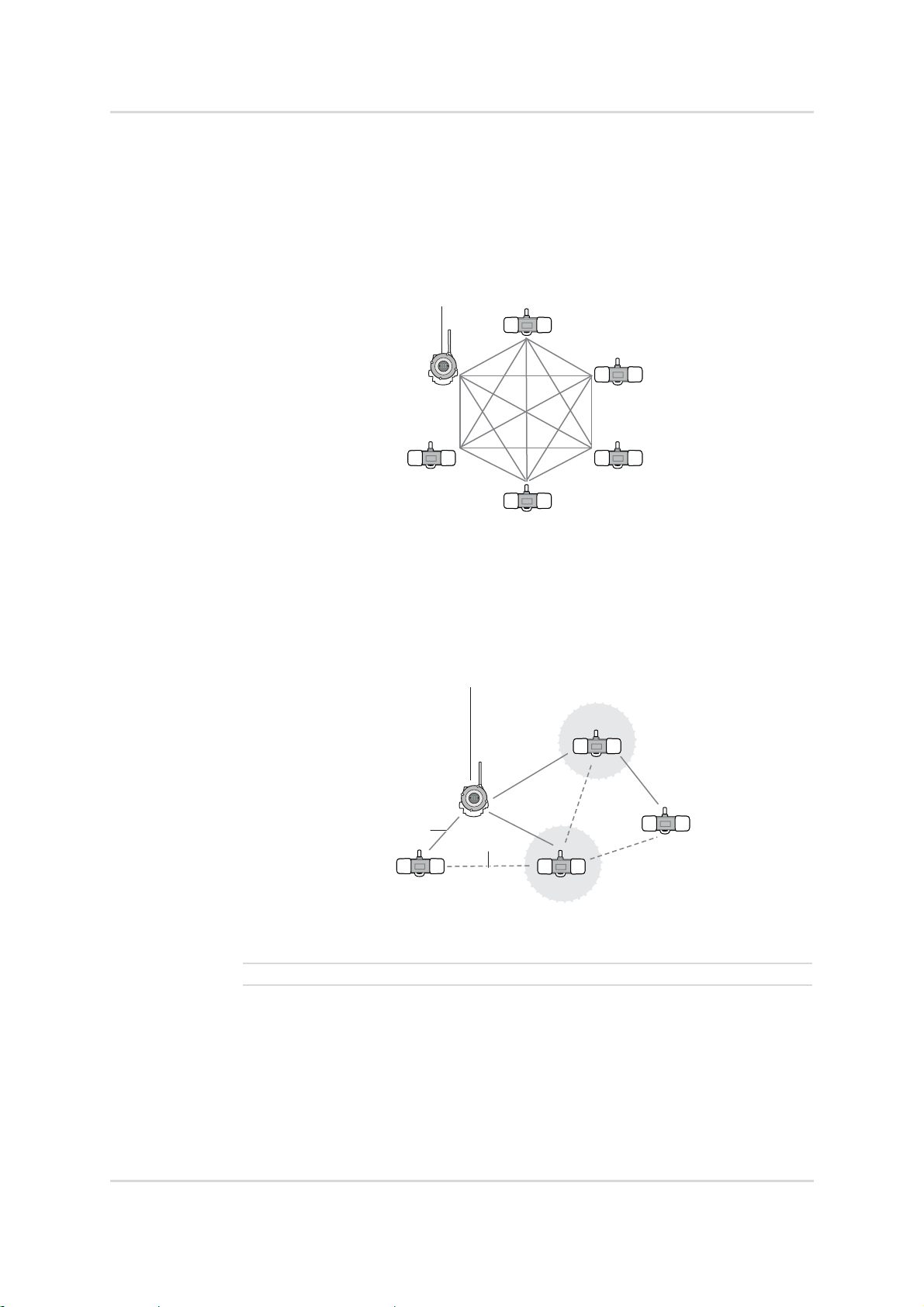
3.2.2 Mesh topology
In a mesh topology, all network participants that are within range communicate with
one another. Field devices, routers and access points can be network participants.
In a mesh network, the data transmission is redundant. If communication over a
field device or a repeater is interrupted, the data is transmitted via other network
participants.
Fig. 5 Mesh topology
ISA100 WirelessTM basics
4093640937
3.2.2.1 Partial mesh topology
The mesh topology and star topology can be mixed. This combination is called a
partial mesh topology or star-mesh topology. In this topology, a core network, in
which all network participants are interconnected, is expanded with network
participants that are no longer connected with all network participants.
Fig. 6 Partial mesh topology
1 Preferred communication channel
2 Redundant communication channel
1
2
Technical Manual | Wireless communication 15
Page 16

ISA100 WirelessTM basics
3.2.3 Comparison of star topology and mesh topology
Network cards are best compared by using the most important criteria for networks:
Reliability and latency.
Reliability
In a mesh network, network participants exchange information with each other (IoT
approach). If one network participant fails, communication is still possible. If a
network participant fails in a star topology, communication can fail.
Latencies
The latency of star topologies is usually less than that of meshed ones due to the
field devices being directly connected to an access point.
3.3 Network performance and network configuration
The wireless connection between field devices and the access point depends
greatly on the surroundings. The connection is best when there is an unobstructed
line of sight between the two. Oftentimes, however, there is no line of sight (due to
intervening pipes or walls, for example). If the line of sight is obstructed, routers or
the reflective properties of the obstacles themselves are used.
3.3.1 Signal quality
The signal quality of wireless transmissions depends on the signal strength (RSSI)
and the signal integrity (PER or TxFail rate). The RSQI range is another indicator of
signal quality.
PER or TxFail rate
This value represents the error rate during data transmission from the field device
to the backbone. This value is displayed as a percentage. The lower the value, the
better the integrity of data transmission. High values show poor data transmission
integrity. Poor data integrity can be caused by unfavorable communication paths or
interferences (other wireless technologies or obstacles, for example).
The expression and the limit values of this error rate depend on the manufacturer of
the system manager. The error rate can be expressed either as PER (packet error
rate) or as a TxFail rate.
RSSI
RSSI (received signal strength indication) shows the received signal strength
between the field device and the access point. RSSI is expressed in dBm (decibelmilliwatts). The received signal strength is always shown as a negative number.
The closer the value is to zero, the better the wireless connection.
RSQI
RSQI (received signal qualitiy indication) shows the received signal strength
between the field device and the access point. RSQI is a calculated value. Higher
values indicate better data transmission than lower values. Four quality classes are
defined in the standard ISA-100.11a (see table below).
16 Technical Manual | Wireless communication
Page 17
ISA100 WirelessTM basics
P6 P6
Signal quality values and their meaning
The interpretation of the value ranges can be adjusted in some system managers.
The following table provides an example of the ranges for the purpose of
orientation.
Indicator Value range Meaning
PER / TxFail rate 0 to 15 % Good
15 to 100 % High
RSSI -75 to -25 dBm Good
-85 to -75 dBm Acceptable
-100 to -85 dBm Poor
RSQI 196 to 255 Excellent
128 to 195 Good
64 to 127 Acceptable
0 to 63 Poor
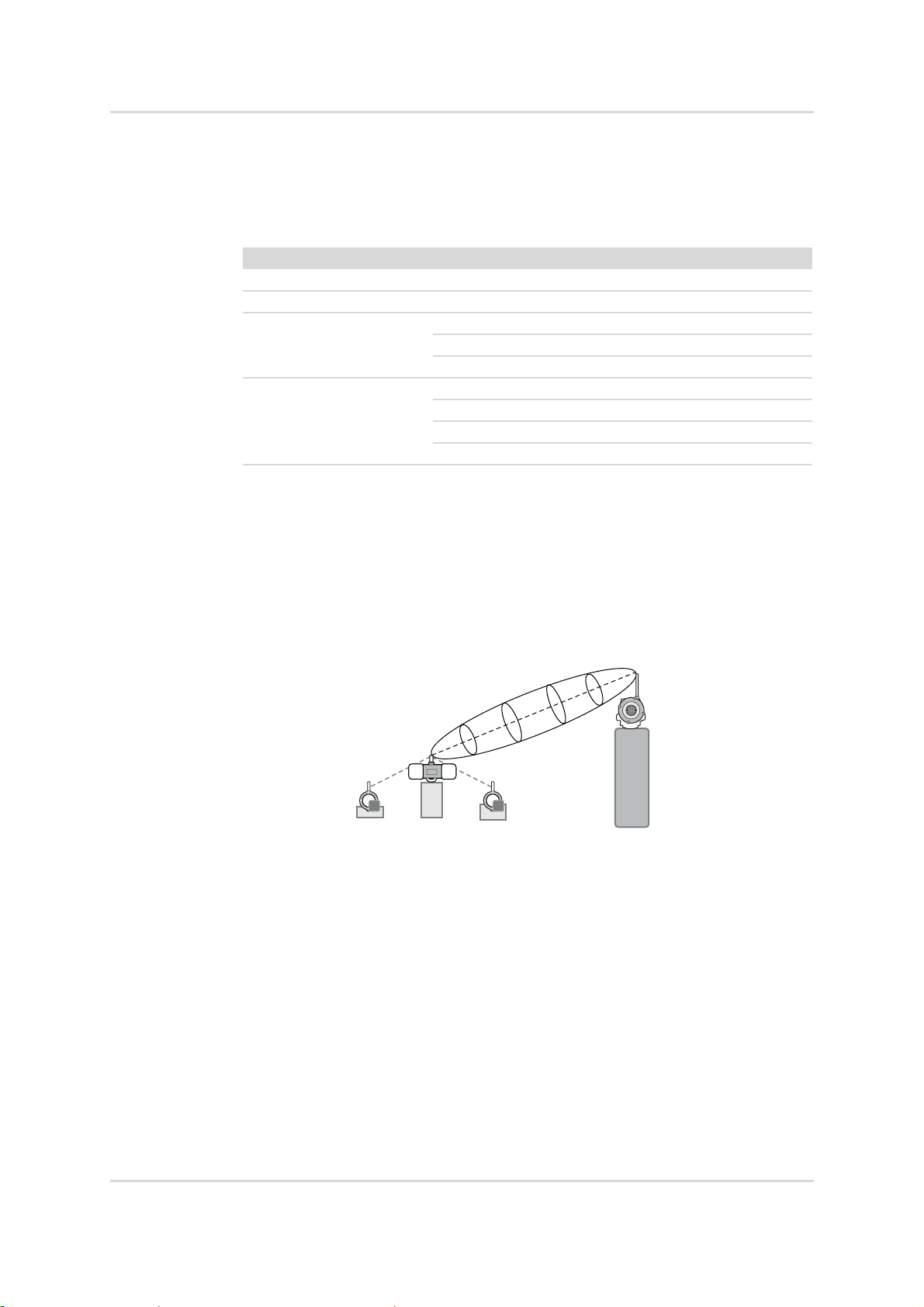
Fresnel zone
Signal quality can be disrupted by obstacles even if transmitter and receiver have
line of sight. Disruption due to obstacles occurs when obstacles are located in the
Fresnel zone. The Fresnel zone is an elliptical area formed around the line of sight,
whose diameter increases with the transmission range. It is therefore
recommended to install antennas as high up as possible to ensure longer distances
are covered.
Fig. 7 Line of sight between field device and access point with an elliptical
Fresnel zone
38862
Technical Manual | Wireless communication 17
Page 18

ISA100 WirelessTM basics
1
2
3
P6
Reflections
Metallic objects and structures can reflect radio waves. If line of sight is obstructed,
this effect can be utilized.
Fig. 8 Alternate communication paths via reflective objects
1 Preferred communication path (Primary-Path)
2 Alternate communication path via reflection ensured.
3 Obstructed, direct communication path (Line-Of-Sight)
38868
3.3.2 Network coverage
It can occur that network coverage is weaker in some areas. Weak spots such as
these are usually due to structural conditions. The routers (repeaters) and field
devices with hop point functionality are used to balance weak spots in network
coverage.
Remote antennas are another possible way to alleviate weak spots. The antenna is
positioned in a spot with good network coverage. The antenna is then connected
via cable with the gas warning device. The gas warning device can then be installed
in the area where it is required without negatively affecting communication.
Site survey (Site-Survey)
To determine the network coverage at the installation area of the gas warning
device, a site survey (measurement and analysis of the site) can be conducted in
advance.
The site survey generally involves the creation of a heat map. The heat map is a
presentation of the site, which marks the quality of the network coverage in color.
18 Technical Manual | Wireless communication
Page 19

Network size and range
The range depends on the sources of interference (e.g. building development),
infrastructure used and thus differs from location to location. The following table
shows the typical ranges for three sample environments.
Environment Example Range [m]
Free field
No sources of interference
Environment with few
sources of interference
Environment with many
sources of interference
3.3.3 Sub-networks
Sub-networks are smaller networks which together form the main network. Subnetworks are established by access points.
ISA100 Wireless
theoretically contain up to 2
practice for various reasons (e.g. flexibility for extensions and stability), addresses
still need to be assigned to the field devices at the sub-network level. Every field
device is assigned a 16 bit address on the sub-network level. On the main network
level, the 16 bit address is increased to 128 bits.
ISA100 WirelessTM basics
Fuel depot 500
Refinery (few buildings
200
and plants)
Oil platform 50
TM
allows for many sub-networks. Every sub-network can
16
field devices. While this possibility is not utilized in
For data transmission between sub-networks, the data packets are sent to the
backbone router. The BBR forwards the data packets to the target sub-network.
Communication between sub-networks is not yet provided for gas detection
applications. These applications send sub-network data packets only to the
backbone. Exchanging data between sub-networks is not yet implemented.
P6
P6
P6P6
40972
Fig. 9 Sub-networks are established by various network participants.
Technical Manual | Wireless communication 19
Page 20

ISA100 WirelessTM basics
3.3.4 Sky mesh
Field device access points are installed above field devices and establish their own
sub-networks. FDAPs then communicate wirelessly with the access point or the
backbone router. The field devices can utilize the reflective properties of the
surrounding objects for communications to the FDAP. The FDAP itself
communicates via line of sight with the access point.
The line of sight’s Fresnel zone should not be obstructed by structures (cranes or
masts, for example).
38326
P6P6
Fig. 10 Sub-networks are established by access points at a higher altitude.
3.3.5 Network configuration with retrofitted field devices
Field devices not actually designed for wireless communication can be retrofitted
with antennas. The antenna contains a ISA100 Wireless
integrated into the network as a wireless field device.
The ISA100 Wireless
device’s signals to the ISA100 Wireless
TM
module is connected to a converter that converts the field
TM
protocol. The field device’s signals can
be digital signals (RS485 Modbus, HART) or analog 4–20 mA signals. The
universal commands are supported bidirectionally for digital signals. Analog 4–
20 mA signals have to follow the NAMUR NE43 recommendation.
Some converters come equipped with built-in batteries for supplying connected
field devices with power.
TM
module. This module is
P6P6
20 Technical Manual | Wireless communication
Page 21

ISA100 WirelessTM basics
1
2
3
P8
Fig. 11 Retrofitted gas warning device (Dräger Polytron® 8xx0)
1
Antenna with ISA100 Wireless
2 Converter for digital or analog communication
3 Retrofitted field device that originally only communicates by wire
The following components from Yokogawa have been tested and approved by
Dräger as suitable field devices for retrofitting purposes (as at September 2020).
– FN110 Field Wireless Communication Module
ISA100 Wireless
TM
module (antenna)
– FN310 Field Wireless Multi-Protocol Module
Converter for digital communication (HART7 and RS485 Modbus)
– FN510 Field Wireless Multi-Function Module
Converter for analog communication (4–20 mA)
TM
module
42275
3.3.6 Network configuration for small networks
For small networks, solutions are available that combine access point and system
manager in one component. This solution saves steps during network configuration,
but is less effective than conventional installations.
2
1
P6
Fig. 12 Small network with system manager and backbone router in one
component
1
Antenna with ISA100 Wireless
TM
module that combines system manager and
backbone router
2 Interface adapter
3 Control unit
3
42273
Technical Manual | Wireless communication 21
Page 22

ISA100 WirelessTM basics
The following components from Yokogawa have been tested and approved by
Dräger for small networks (as at September 2020).
– FN110 Field Wireless Communication Module
ISA100 Wireless
TM
module (antenna)
– LN90 Interface Adapter
Interface adapter between the FN110 and the control unit
FN110 field wireless communication module
An FN110 consists of an antenna and an ISA100 Wireless
TM
connected to an interface adapter (LN90) which establishes the connection to a
controller via Modbus RTU.
The FN110 can only establish 1 sub-network. Field devices in this sub-network can
only be configured in star topology. Depending on the network’s refresh rate, 10 to
20 field devices can be integrated. SIL2 communication is not possible.
3.3.7 Network configuration with long backbone lines
The use of Ethernet cables limits the length of backbone lines to approx. 100 m. If
backbone lines need to cover long distances, the Ethernet lines can be expanded
with other transmission technologies.
– Fiber-optic cables (FOC)
To use fiber-optic cables, a converter between the backbone and the system
manager must be installed. The converter converts the signals of the fiber-optic
cable to signals for Ethernet cables (conversion between 100BASE-TX and
100BASE-FX).
– Copper cables for DSL transmission
To be able to use DSL, modems must be installed at the transfer point from the
Ethernet to the copper cables.
module. The FN110 is
Long backbone with fiber-optic cable
1
2 3
Fig. 13 Long backbone with fiber-optic cable
1 Backbone as fiber-optic cable (100BASE-FX)
2Converter
3 Backbone as Ethernet cable (100BASE-TX)
42274
22 Technical Manual | Wireless communication
Page 23

ISA100 WirelessTM basics
1
2
1
2
3
The following components from Yokogawa have been tested and approved by
Dräger for conversion between fiber-optic and Ethernet cables (as at September
2020).
– Field Wireless Media Converter (YFGW610)
Long backbone with DSL transmission
Fig. 14 Long backbone with DSL modem
43001
1 Backbone as Ethernet cable (100BASE-TX)
2DSL modem
3
Backbone as copper cable (e.g. BFOU 2x2x1.5 mm
2
)
The following components from Phoenix Contact have been tested and approved
by Dräger for conversion between Ethernet and copper cables (as at September
2018).
– TC EXTENDER 2001 ETH-2S
– TC EXTENDER 6004 ETH-2S
Technical Manual | Wireless communication 23
Page 24

ISA100 WirelessTM basics
1
2 3
3.3.8 Network configuration with a 4–20 mA control unit
The signal output of the system manager is digital (Modbus, for example). To be
able to use analog 4–20 mA link cards of control units, a digital-to-analog converter
must be inserted in between.
Fig. 15 Network configuration with a 4–20 mA control unit
1 System manager with digital signal output
2 Digital-to-analog converter
3 Control unit with 4–20 mA link card
42284
The following Phoenix Contact component has been tested and approved by
Dräger for converting the system manager’s digital signals to an analog 4-20 mA
signal to the controller (as at September 2018).
– ILC 131 ELH / IB IL AO 2UI-PAC
24 Technical Manual | Wireless communication
Page 25

ISA100 WirelessTM data transmission basics
4 ISA100 WirelessTM data transmission basics
The requirements for data transmission via wireless network in industrial settings
differ greatly from those for WLAN networks. In WLAN networks, the loss or delay
of data packets usually "only" leads to user frustration. In an industrial network,
however, this can lead to processes being halted or to injuries or material damage.
To ensure secure data transmission, the frequency spectrum and communication
paths are continuously monitored.
Communication paths are the paths the data packets follow through the network.
Monitoring is done via the field devices’ performance data.
Various mechanisms are executed based on this performance data.
– Time-Division-Multiple-Access (TDMA) (deterministic transmission and time
diversity)
– Clear-Channel-Assessment (CCA) (collision avoidance)
– Path-Diversity, Graph-Routing (different communication paths)
– Automatic-Repeat-reQuest (ARQ) (data packet acknowledgment)
– Blacklisting, Adaptive-Hopping (frequency spectrum management)
Every mechanism contributes to the error-free transmission of data within a defined
time period.
For this, every mechanism fulfills at least one of the 3 data integrity requirements.
– Latency
Data must reach the recipient without undue delay.
– Convergence
Data must remain complete and unaltered on its way to the recipient.
– Deterministics
Data must reach the recipient within the predetermined time.
4.1 Frequency band and bandwidth
Radio channel and frequency
A radio channel is a frequency range for data transmission. The wider the
frequency range, the more data can be transmitted.
The distance between radio channels and the width of the frequency range
(bandwidth) are defined. These channel characteristics are also known as the
channel spacing.
ISA100 Wireless
The bandwidth of a radio channel is 2 MHz. The distance between 2 radio channels
(distance from center of one radio channel to center of the next radio channel) is
5MHz.
ISA100 Wireless
standard 802.15.4 (channels 11-26). This frequency band can be used world-wide
with no license needed.
TM
channel spacing
TM
uses the 2.4 GHz ISM frequency band according to IEEE
Technical Manual | Wireless communication 25
Page 26

ISA100 WirelessTM data transmission basics
25 MHz
22 MHz
11
12
13 14 15
16
17
18 19 20
21
22
23 24 25
26
2 MHz5 MHz
WLAN channel 11
WLAN channel 6
WLAN channel 1
2425 MHz 2450 MHz 2475 MHz
Spectrum
ISA100
Channels
ISA100 WirelessTM shares this frequency band with channels defined for WLAN
transmission. Channels 1, 6 and 11 partially overlap with the wireless channels of
the ISA100 Wireless
Wireless
TM
channel spacing are not overlapped.
TM
channel spacing. Channels 15, 20, 25 and 26 of the ISA100
Fig. 16 ISA100 Wireless
4.2 Data integrity
TM
channel spacing and frequency band with overlapping
44320
4.2.1 Frequency hopping
When frequency hopping, the field devices change the frequency. Poor
performance data may make a change of frequency necessary. If the is the case,
an ARQ is executed.
Frequency changes follow the predefined hopping scheme (Patterns). This
sequence is assigned during provisioning of the field device.
4.2.2 Hopping patterns
Hopping patterns determine on which channels transmission and reception take
place in a time slot. Duration and sequence are predetermined.
TM
defines 3 hopping patterns.
ISA100 Wireless
Slotted hopping
Data is transmitted once on every channel in a time slot. This way, a relatively large
amount of time passes before transmission and reception occurs again on a
channel.
Slotted hopping is suitable for regular data that is transmitted synchronously. It is
therefore not suitable for event-based transmissions (alarms, for example). Field
devices wait to transmit and receive data until their channel’s turn. The time window
for this is relatively small.
Slow hopping
Transmission and reception can occur on every channel for the duration of exactly
one time slot. Slow hopping is therefore better suited for event-based transmissions
that must be sent immediately. However, the energy consumption of a field device
is increased due to the device having to wait for incoming messages for a longer
time.
26 Technical Manual | Wireless communication
Page 27

ISA100 WirelessTM data transmission basics
time
Timeslot 1
Channel
12
11
13
14
15
16
Timeslot 2
Hybrid Hopping
Slotted Hopping Slow Hopping
11
12
13
14
Channel
15
16
Timeslot 1
Timeslot 2 Timeslot 1 Timeslot 2
time
Fig. 17 Comparison of slotted hopping and slow hopping
Hybrid hopping
Hybrid hopping combines the advantages of slotted and slow hopping. The
combination of slow and slotted hopping is configurable. This way, planned
transmissions can be performed in small time slots and unplanned transmissions
can be performed on another channel that has a longer time slot available.
For further information see: "Time-Division-Multiple-Access (TDMA)", page 28.
3892138923
Fig. 18 Hybrid hopping
4.2.3 Standard hopping pattern
ISA100 WirelessTM defines 5 standard hopping patterns. A standard hopping
pattern defines the channel sequence. Every field device must support the pattern.
A 19, 12, 20, 24, 16, 23, 18, 25, 14, 21, 11, 15, 22, 17, 23, 26 (optional)
B Reverse order of A
C 3, 15, 20, 25
D Reverse order of C
E 11, 12, 13, 14, 15, 16, 17, 18, 19, 20, 21, 22, 23, 24, 25, 26 (optional)
Technical Manual | Wireless communication 27
Page 28

ISA100 WirelessTM data transmission basics
4.2.4 Duo-Cast
Duo-Cast (dual transmission) is the option of sending data packets to access points
via 2 communication paths simultaneously. The access points must be
synchronized for this. When Duo-Cast is active, communication is only possible
with the synchronized access points. This creates a star topology. Other topologies
(mesh, partial mesh) are excluded.
Fig. 19 Communication between field devices is not possible with duo-cast.
38254
Duo-Cast is configured in the system manager during Provisioning. Some
system manager user interfaces allow for setting Duo-Cast and mesh topologies.
However, these settings cannot be downloaded to the system manager.
4.2.5 Time-Division-Multiple-Access (TDMA)
Time-Division-Multiple-Access defines the time slot in which messages can be sent
and received on certain channels. The time slot duration can be set variably. It can
be between 10 and 12 ms.
The variable duration enables the close timing of many short transmissions.
To send a number of status messages from different field devices as a bundle (from
a router/access point to the backbone), a time slot with a longer duration is suitable.
4.2.6 Clear channel assessment (CCA)
Clear channel assessment is performed by a field device before sending data
packets. The field device checks whether the channel is free. If the channel is not
free, the field device waits a set amount of time (generally several milliseconds)
before attempting to send the data packet again.
4.2.7 Automatic-Repeat-reQuest (ARQ)
Automatic repeat request enables sending unacknowledged data packets on
another radio channel and via a different communication path.
Each received data packet must be acknowledged by the receiving participant
within a set amount of time.
28 Technical Manual | Wireless communication
Page 29

ISA100 WirelessTM data transmission basics
Time slot 1
11
12
13
14
Channel
15
16
Fig. 20 Repeat transmission via another channel
4.2.8 Blacklisting
Blacklisting is the exclusion of channels by the system manager. The system
manager excludes channels based on performance data sent by the field devices.
Other radio technologies can be the source of poor performance data. Field devices
avoid these excluded channels during frequency hopping.
Manual blacklisting
Wireless channels can also be blocked manually in the system manager. When the
settings have been performed in the system manager, the system manager
distributes the information in the network. The network participants are updated.
ARQ
Time slot 2
38939
Time
4.2.9 Adaptive hopping
Adaptive-Hopping is very similar to Blacklisting. As with Blacklisting, the
performance data is used to decide whether an action is performed. An action in
this case is the switch to another channel. In contrast to Blacklisting, the field device
itself decides this. This enables the field device to adjust itself independently to the
frequency spectrum without depending on the system manager.
Adaptive hopping is activated by default.
4.2.10 Path diversity
Path diversity continuously adjusts redundant communication paths. This
adjustment is made based on the collected performance data.
Redundant paths are established by the network itself. Users do not have to take
action.
Routing and Forwarding contribute to path diversity.
Forwarding
Forwarding is oftentimes also called Routing. Forwarding, however, is the decisionmaking process of a network participant on which communication path the data
packets are forwarded over.
Technical Manual | Wireless communication 29
Page 30

ISA100 WirelessTM data transmission basics
Routing
Data packets take different communication paths. The routing is the way specified
by the system manager.
Routing is possible in different ways. For further information see: "Types of
routing", page 30.
4.2.11 Types of routing
Routings are predefined communication paths for data packets. The predefined
communication paths can be implemented in various ways.
Graph routing
In graph routing, all possible communication paths in the network are loaded onto
each participant in the form of a routing table. When a data packet is sent, the
sending participant writes the identification of the communication path in the
packet’s header. The next participant compares the identification with the routing
table and forwards the packet.
Source routing
In source routing, the entire communication path is integrated into the data packet.
Every network participant forwards the packet to the node specified in the data
packet itself.
4.3 Data structure
Object-oriented data model
The ISA100 Wireless
describe and distinguish components and tasks of the real world in objects. Objects
are an abstract representation of a specific device component or field device task.
The following task is an example of an object: methane concentration monitoring.
The object must have at least one field for the current measured value data. For the
measured value, Dräger uses the Process value "PV" of the ISA100 Wireless
protocol.
ISA100 Wireless
contain optional standard objects or manufacturer-specific objects.
An example of a manufacturer-specific object is the object for the PROFIsafe
communication (Custom_(“SafeData”)). Observe the following information: "UAP,
objects, attributes and parameters using the example of the GS01 in the Yokogawa
YFGW 410 configurator (as at July 2018)", page 33.
TM
defines obligatory standard objects. In addition, devices can
TM
protocol is object-oriented. Object-oriented models
TM
®
30 Technical Manual | Wireless communication
Page 31

4.3.1 Data fields
ISA100 WirelessTM data transmission basics
Regardless of their status as either standard or manufacturer-specific objects,
objects always contain data fields for alarms, methods
1)
and attributes. Depending
on the command, these are either read, written, triggered, stopped or
acknowledged.
Methods
Methods are actions the corresponding device performs. Examples of methods are
sensor adjustments or firmware updates.
Attributes
Attributes are device values (sensor temperature, for example) or measured
values. ISA100 Wireless
TM
defines 5 classes of attributes (see "Attribute classes",
page 34).
Alarms
Alarms can be set in addition to attributes. They are provided via the "alert reporting
management object" (ARMO).
In order to be more flexible and to reduce complexity, Dräger gas warning devices
do not support the function via ARMO. Measured values are provided as process
values (PV). The user can edit the corresponding alarm values at the control unit.
Editing at the controller is more flexible than via the ISA100 Wireless
TM
protocol at
the gas warning device.
Parameters
The combination of object identifier and an object’s attribute, method or alarm is
called a parameter. The parameter for monitoring the methane concentration would
therefore be: AI_01("METHANE").PV.
AI stands for Analog Input
PV stands for Process Value
Failsafe parameters
For failsafe data transmission (e.g. via PROFIsafe
®
), manufacturer-specific objects
are available in addition to the standard objects. The parameters of the
manufacturer-specific objects are named as "SafeData" with the corresponding
attribute (Custom_00("SafeData").Attribut2(12), for example).
1) Also known as routines or operations.
Technical Manual | Wireless communication 31
Page 32

ISA100 WirelessTM data transmission basics
4.3.2 User application process (UAP)
A device’s objects can be found in the device software in the so-called User
Application Process (UAP). A device can have multiple UAPs. To ensure
compatibility with the system manager, Dräger gas warning devices only have one
UAP.
Every UAP contains a main object which indicates the status of the UAP. Aside from
the status, the main object also indicates the amount and types of the other objects
of the UAP. This main object is called the User Application Management Object
(UAPMO).
User application process n
User application process 1
UAPMO
UAP status
Objects
...
Object n
Object 1
Alarm
Method
Attribute
Fig. 21 UAP with UAPMO and corresponding objects
38824
32 Technical Manual | Wireless communication
Page 33

ISA100 WirelessTM data transmission basics
1
2
3
4
5
6
4.3.2.1 UAP and parameters in the Yokogawa YFGW 410 configurator
The following diagram uses the GS01 as an example to show the display of the
UAP, the corresponding objects, attributes and parameters in the configuration
screen of a system manager (Yokogawa YFGW410).
Here, the UAP with the corresponding UAPMO object and the other objects are
displayed.
38827
Fig. 22 UAP, objects, attributes and parameters using the example of the GS01 in
the Yokogawa YFGW 410 configurator (as at July 2018)
1 UAP with the UAPMO object, the gas concentration monitoring objects and a
Custom object named SafeData
2 Readable DIAG_Status attribute
3 Readable process value (PV) attribute for methane
4 Readable process value (PV) attribute for propane
5 Manufacturer-specific attributes
6 Readable parameters of the UAP02.
4.3.3 Object identifiers
In addition to their names, objects also have unique identifiers. Object identifiers are
16 bits long. They can be used for finding and uniquely identifying them in the
system manager.
UAPMO objects always have the identifier 1 (0x0001). Identifier 2 is reserved for
UDO objects (0x0002). UDO objects are upload/download objects. They are used
to transmit firmware updates.
Technical Manual | Wireless communication 33
Page 34

ISA100 WirelessTM data transmission basics
Dräger-specific object identifiers
In addition to UAPMO and UDO objects, gas warning devices also contain objects
with the following identifiers:
– 6 (0x0006) process value for methane
– 7 (0x0007) process value for propane
– 8 (0x0008) process value for EC sensor measuring gases (hydrogen sulfide, for
example)
4.3.4 Attribute classes
Constant
The values of these attributes must remain constant. If a device is disconnected
from the power supply, reset or rebooted, the values of these attributes must remain
unchanged (the serial number of a wireless node, for example).
Static
The values of these attributes rarely change. These values only change due to an
external trigger. A trigger can be a configuration tool, for example. The values of
these attributes should remain unchanged if a device is disconnected from the
power supply or rebooted (units or operating areas, for example).
Static-volatile
The values of these attributes can change when the device is disconnected from
the power supply or rebooted.
Dynamic
The values of these attributes can be changed by the field device itself. These
values do not have to remain unchanged when a device is disconnected from the
power supply or rebooted (process variables, timers or calculation results, for
example).
Non-bufferable
The values of these attributes may not be cached. These values must be queried
directly from the field device. These values may not be queried from the cache of a
network node (critical safety information, for example).
34 Technical Manual | Wireless communication
Page 35

ISA100 WirelessTM data transmission basics
4.3.5 Data format (without PROFIsafe® communication)
The DIAG_STATUS byte is 4 bytes long and contains information on device
performance and signal properties. The UAP parameters are 4+1 bytes long. Each
parameter includes a status byte that indicates the quality of the value.
Process Value 1, 5 bytes
PV
status
Byte
Process Value 2, 5 bytes
PV
status
Byte
PV
4 byte float
PV
4 byte float
DIAG_STATUS, 4 bytes
Diagnosis info
Not Safety Related
41774
Fig. 23 Example process value data format
4.4 Traffic
ISA100 WirelessTM defines 3 data transmission methods
– Unidirectional, buffered data
– Unidirectional, queued data
– Bidirectional, queued data
Dräger only uses 1:1 data transmission between field devices and the system
manager or F-host. This includes data transmissions via hop points. This data
transmission method is known as client-server service and uses bidirectional,
queued data.
UAP
UAPMO
DIAG_STATUS
AI METHANE
PV
AI PROPANE
PV
Technical Manual | Wireless communication 35
Page 36

ISA100 WirelessTM data transmission basics
UAP
DIAG_STATUS
UAPMO
AI METHANE
AI PROPANE
PV
PV
4.4.1 Data query
UAP data and field device performance are queried cyclically.
The UAP data contains the field device’s parameters (process value for methane
concentration, for example). Each of these parameters returns a value which
provides information on the attribute quality. This value is known as a status byte.
The field device performance contains information on the field device’s status and
signal properties. This data is transmitted in the DIAG_STATUS attribute.
For further information see: "Data format (without PROFIsafe
page 35.
®
communication)",
40915
Fig. 24 Parameter with status byte and DIAG_STATUS attribute during system
manager transmission
4.4.2 Sampling rate and stale limit
Sampling rate
The sampling rate (publication period) determines the time intervals at which uplink
transmissions are sent by the gas warning device.
Stale limit
The stale limit, together with the sampling rate, determines the time slot within
which uplink transmissions from the gas warning device must arrive at the system
manager. If no uplink transmissions arrive within the time slot, the gas warning
device will be marked as not available.
The following formula illustrates the relationship between sampling rate, time slot
and stale limit.
Time slot = stale limit x sampling rate
36 Technical Manual | Wireless communication
Page 37

ISA100 WirelessTM data transmission basics
Example: Sampling rate and stale limit
The following example illustrates the relationship between stale limit, sampling rate
and the time slot after which the gas warning device will be marked as unavailable.
In this example, the failure of the gas warning device or a poor wireless interface
will be recognized after a time slot of 60 seconds.
Stale limit = 30
Sampling rate = 2 seconds
43009
2 s
2 4 6 8 10 12 14 16 18 20 22 24 26 28 30
1 3 5 7 9 11 1315171921 23 25 2729
OK
60 s
Fig. 25 Relationship between the sampling rate and stale limit
Stale limit
NOK
Technical Manual | Wireless communication 37
Page 38

ISA100 WirelessTM data transmission basics
GAS!
1
2
Auswerteeinheit
System-Manager
4.4.3 Network and energy management with ISA100 wireless
communication
The wireless communication takes place between the field device and the system
manager. Field devices must transmit new sampling rate and stale limit data within
the time slot defined in the system manager. If new data does not arrive within the
predefined time limit, the field device in the system manager and in the controller
will be marked as unavailable.
The number of available time slots for the uplink transmission, i.e. from field device
to system manager, is determined by the sampling rate. If there is no internal alarm
condition, not all uplink time slots will be used (see illustration below). This mode of
operation saves energy. If there is an internal alarm condition, all uplink time slots
will be used to ensure quick communication. The relationship between available
time slots and time slots used in the absence of an alarm condition is described as
the publication factor. The threshold value for the internal alarm condition and the
publication factor are determined in the field device.
49320
Fig. 26 Relationship between time slots and alarm conditions
Blue Time slots for uplink transmissions
1 Time slots are not used because no alarm condition is present.
2 The presence of an alarm condition means all time slots will be used.
38 Technical Manual | Wireless communication
Page 39

ISA100 WirelessTM data transmission basics
4.4.4 Device performance information
Energy life
The battery status gives an estimate of the remaining operating time of the field
device. This status is also displayed as "Days Left".
Unit: Values greater than 0 specify the remaining operating time in months. If the
remaining operating times are only days, values smaller than zero are displayed.
Listen rate
Duration for which the field device can have its receiver switched on.
Unit: seconds or hours
Transmit rate
Duration for which the field device can have its transmitter switched on.
Unit: data packets or minutes
Advertisement rate
Duration for which the field device can transmit Advertisements. Field devices that
support OTA send Advertisements. For further information see: "Over the air
provisioning (OTA)", page 48.
Unit: Advertisements or minutes
Technical Manual | Wireless communication 39
Page 40

Transmission basics for PROFIsafe® communication
P6
P6
P6
P6
5
3
1
2
4
5 Transmission basics for PROFIsafe®
communication
With PROFIsafe® communication, failsafe field devices (F-slave) and failsafe
controllers (F-host) communicate directly with each other. The infrastructure (e.g.
system manager) only forwards the data.
The PROFIsafe
Wireless
TM
follow the specifications described in this document (e.g. requirements from 4).
®
communication takes place in the black channel of the ISA100
communication. Communication via ISA100 WirelessTM continues to
38256
Fig. 27 PROFIsafe
®
communication between gas warning device (F-slave) and
controller (F-host)
1
2
3
Wireless standard communication via ISA100 Wireless
PROFIsafe
PROFIsafe
4 Field device (hop point) that forwards the tunneled message without
processing.
5
The PROFIsafe
Controller for interpreting the PROFIsafe
®
protocol allows for the use of a failsafe network for safety-oriented
applications according to the following standards:
– SIL 3 (IEC 61508 / IEC 62061)
– Safety category 4 (EN 954-1)
– PL "e" (ISO 13849-1)
5.1 Black channel principle
The black channel principle enables the exchange of system- and safety-relevant
data over the same network (Physical Layer). System-relevant data in this case can
be the sensor vitality or adjustment interval status, etc. Safety-relevant data
comprises error messages, alarm acknowledgments and pre- and main alarms.
TM
®
in black channel via ISA100 WirelessTM protocol
®
in black channel via PROFINET protocol
®
signals
protocol
40 Technical Manual | Wireless communication
Page 41

Transmission basics for PROFIsafe® communication
PROFIsafe PROFIsafe
ISA100 Wireless Standard
PROFINET
Safety-relevant data is only evaluated by the corresponding F-slave and the F-host.
All other network participants such as hop points, access points, or system
managers are considered transparent.
38376
Fig. 28 PROFIsafe
®
communication
5.2 Data integrity for PROFIsafe® communication
The following measures and parameters guarantee the integrity of the data
exchanged between F-host and F-slave in the black channel.
– Signal of life
Data packages must be sent sequentially. A sequential number counter in the Fhost and F-slave ensures this is the case.
– Watchdog
Received data packets must be acknowledged.
– Safe address
Transmitter and receiver must have a unique identifier.
– Time stamped security
A timeout counter always starts when the transmission of a data package
begins. The data package will only be accepted if it is received within a
predefined “WD_timeout” time limit. F-host and F-slave have their own counters
and a time stamp for uplink and downlink transmission.
– Cyclic redundancy check - CRC (cyclic block check)
Data completeness and consistency are checked.
In addition to completeness and consistency of the data, whether configuration
of the F-slave has changed is also verified. The CRC contains a parameter
which provides information about the configuration of the F-slave. This
parameter is transmitted to the F-host with the network integration of the F-slave
and synchronized during data exchange. If configuration of the F-slave changes,
the parameters specified during network integration and the transmitted
parameters are no longer identical. If the CRC parameters are not identical, an
SIL 2-compliant communication will no longer be possible.
Technical Manual | Wireless communication 41
Page 42

Transmission basics for PROFIsafe® communication
5.2.1 PROFIsafe® network constraints
– The maximum number of hop points connected in series must be observed for
short response times For further information see: "Hop points in a sub-network",
page 13.
– The IP addresses within a sub-network must be unique.
– If 2 sub-networks with the same IP address space are connected to one router,
that router must be a multi-port router.
5.3 Data structure
5.3.1 Data fields
In addition to the data fields for communication via ISA100 WirelessTM, further data
fields from the manufacturer-specific objects will be required for the PROFIsafe
communication.
Failsafe parameters
For failsafe data transmission (e.g. via PROFIsafe
are available in addition to the standard objects. The parameters of the
manufacturer-specific objects are named as "SafeData" with the corresponding
attribute (Custom_00("SafeData").Attribut2(12), for example).
®
), manufacturer-specific objects
®
42 Technical Manual | Wireless communication
Page 43

Transmission basics for PROFIsafe® communication
PROFIsafe
Empty
CRC
PROFI
status
PROFI
UAP
DIAG_STATUS
UAPMO
Custom SafeData
Attribute
Gas ReadingGas Reading
Uplink
PV
status
PV
4 byte float
Diagnosis info
Not Safety Related
Process Value, 5 bytes
DIAG_STATUS, 4 bytes
AI METHANE
PV
Downlink
PV
status
PV
4 byte float
PROFI
CRC
PROFIsafe, 9 bytes
PROFI
status
5.3.2 Data format for PROFIsafe® communication
In addition to standard data formats, manufacturer-specific custom parameters
(SafeData) are also transmitted during PROFIsafe
®
communication
41772
®
Fig. 29 Example PROFIsafe
process value data format
5.4 Traffic for PROFIsafe® communication
PROFIsafe® communication takes place between F-host and F-slave. F-slaves are
passive. They can only respond to messages from the F-host. When the F-host has
received the response, the next message is sent directly.
F-slaves must respond within a set time period. If there is no response within the
predefined time period, the F-slave is marked as unavailable in the control center.
Each message must be followed by a reply (one-to-one communication). The Fslave can only send data once a new message has been sent from the F-host.
Stale limit, sampling rate and publication factor for PROFIsafe
The settings for ISA100 WirelessTM communication for stale limit, sampling rate
(publication period) and publication factor are also valid during PROFIsafe
communication. For further information see: "ISA100 Wireless
basics", page 25.
®
®
TM
data transmission
Technical Manual | Wireless communication 43
Page 44

Transmission basics for PROFIsafe® communication
OK
? ? ?
NOK
?
?
? ?
GAS!
OK NOK NOK NOK
1
2
Auswerteeinheit
System-Manager
Uplink and downlink transmissions
Downlink transmission is the transmission of data from the F-host to the F-slave.
The F-slave responds with an uplink transmission.
Time slots for uplink and downlink transmissions
The sampling rates set in the system manager determine the available time slots for
the downlink transmission to the F-slave and the uplink transmission to the F-host.
The threshold value for the internal alarm status is set in the field device. If no alarm
condition is present, not all uplink time slots will be used. This mode of operation
saves energy. As the response to an F-host message is delayed until just before the
subsequent F-host message is expected, the field device is always prepared and
ready to immediately report an alarm.
If an alarm condition is present, the F-slave (field device) always reacts immediately
to the message from the F-host.
49316
Fig. 30 Relationship between transmissions and alarm conditions
Blue Time slots for downlink transmissions (direction F-slave) and uplink
transmissions (direction F-host)
1 Uplink time slots are not used because there is no alarm condition
present.
2 Because an alarm condition is present, the first available time slot is
used for uplink transmissions.
44 Technical Manual | Wireless communication
Page 45

Network integration (provisioning) of gas warning devices
6 Network integration (provisioning) of gas
warning devices
Gas warning devices can be integrated into networks in two ways.
– Network integration with a provisioning device "Out of band" (OOB)
In this case, a provisioning device reads out the gas warning device on-site and
sets values. The read-out data is then loaded into the system manager. A
provisioning device can be a handheld scanner or laptop with the corresponding
software, which communicates with the gas warning device via an infrared
interface, Bluetooth
– Wireless network integration "Over the air" (OTA)
In this case, the gas warning device joins an open (unsecured) provisioning subnetwork. The gas warning device is then transferred from this sub-network to the
operative sub-network.
During network integration, various settings and parameters are set for the gas
warning device and the device is integrated into the network. The settings are made
in the configuration software of the system manager. The configuration software is
called up in the browser of a computer (Microsoft Internet Explorer and Microsoft
Edge are currently suitable options).
®
, or wired adapter.
6.1 Network integration parameters
6.1.1 Modbus parameters
The parameters for the device status and process values are mapped to the
Modbus registers (16 bits) in the configuration software of the system manager.
Process values (PV) occupy 3 registers. The status byte of the process values
occupies the first 8 bits of the first register. The process value (32 bit floating point
number) is divided among the other two registers.
The device status in the DIAG_STATUS parameter is mapped to 2 registers.
Several gateways (e.g. Yokogawa) insert a status byte into the preceding register.
This gateway status byte is ignored as the content has already been provided by
the PV status byte.
6.1.2 PROFIsafe® traffic
PROFIsafe® parameters contain data for the parameterization and operation of
failsafe networks. The integrity of the data is verified by the receiver.
The following parameters are required for network integration.
– F-device address (safe address of the F-slave)
Unique address of a field device in the network for failsafe data transmission.
– F-host address (safe address of the host)
Unique address of the control unit in the network for failsafe data transmission.
– Watchdog timeout
The time [ms] that may elapse after sending a data packet is entered here (timestamped security).
–SIL
Contains the expected SIL.
Technical Manual | Wireless communication 45
Page 46

Network integration (provisioning) of gas warning devices
– iParameter CRC
The configuration of the F-slave defines the value of this parameter. The F-slave
parameter is stored in the F-host during network integration. For further
information see: "Data integrity for PROFIsafe
– With Dräger Polytron
Dräger PolySoft configuration software (Version 1.9.0 or later).
– With GasSecure GS01, possible values for this parameter can be found in
the GS01 and GS01-EA Safety Manual (Doc-ID 21440).
®
6100 EC WL, this parameter is read out using the
®
communication", page 41.
6.2 Out Of Band Provisioning (OOB, Yokogawa gateway
only)
A provisioning device is required for OOB. OOB communication devices include the
infrared adapter (e.g. Actisys ACT-IR224UN-LN96-LE), BLE (Bluetooth Low
Energy), and wired front ports (e.g. serial GS01 adapter). Various data and files are
required for the network integration of gas warning devices and provisioning
devices:
– Information on stale limit and sampling rate
– Capability file (CF file)
1)
for the gas warning device
These files contain information from the gas warning device. They can be
compared to drivers for devices connected to a computer.
– Provisioning file (.ypif file)
This file is created with the provisioning device that is connected to the field
device and contains the following information:
– Date and time of the provisioning file creation
–Join-Key
The join key is a 128-bit-long alphanumeric key which is synchronized during
network integration in the system manager.
– Device tag of the gas warning device
The device tag is the gas warning device’s unique identifier in the network.
– EUI64 address
The EUI64 is the gas warning device’s world-wide unique identifier. It is
64 bits long and is formatted as a standard MAC address.
–Network ID
The network ID is the unique identifier of the network into which the gas
warning device is integrated.
1) Device description files (DD) are not currently supported (as at September 2020).
46 Technical Manual | Wireless communication
Page 47

Network integration (provisioning) of gas warning devices
Network integration with provisioning device
The integration of gas warning devices into a wireless network can be divided into a
few main steps.
1. Create the gas warning device’s provisioning file (.ypif file).
A connection between the gas warning device and a provisioning device (a
laptop, for example) with the corresponding software is required for this. For
Polytron
®
6100 EC WL and Polytron® Repeater ISA100, PolySoft (Version 1.9.0
or higher) is the configuration tool, while the GasSecure GS01 Configurator is
used for GS01. Wireless products from third-party providers may require other
tools (e.g. FieldMate for Yokogawa products).
a. Set the network ID
b. Create a join key
c. Assign the device tag of the gas warning device
2. Read the provisioning file into the system manager.
3. Determine the gas warning device’s task (hop point, simple I/O field device or
both).
4. Determine the communication paths for the gas warning device.
5. Read the gas warning device’s capability file (CF) into the system manager.
6. Set the parameters of the gas warning device.
Values for the read and write parameters must be set in the system manager
(the process value for the gas concentration, for example).
7. Set the properties for reading and writing parameters
(stale limit and sampling rate, for example).
8. Save the settings in the system manager.
The settings made in the system manager’s configuration software must still be
saved in the system manager. In the configuration software, saving is often
called "downloading".
✓ The system manager updates the network and the gas warning device with the
data entered.
Technical Manual | Wireless communication 47
Page 48

Network integration (provisioning) of gas warning devices
6.3 Over the air provisioning (OTA)
Neighbor discovery and advertisements
Some field devices support OTA provisioning. OTA provisioning integrates new field
devices directly from the system manager. No provisioning device is required.
A neighbor discovery is performed by some field devices for this function. These
field devices send Advertisements. A field device wishing to be integrated into the
network responds to the advertisements.
Wireless network integration (OTA)
The wireless network integration of gas warning devices can be divided into a few
main steps.
1. Set the gas warning device to default via the configuration software of the gas
warning device.
2. Turn on the gas warning device.
The gas warning device waits for Advertisements
3. Add the gas warning device in the configuration software of the system
manager.
The system manager searches for and establishes the communication paths
and access points for the gas warning device.
4. Read the gas warning device’s capability file (CF) or the device description file
(DD) into the system manager.
5. Set the parameters of the gas warning device.
The read/write parameters must be set in the system manager (send/uplink and
receive/downlink).
6. Set the properties for reading and writing parameters
(stale limit and sampling rate, for example).
7. Download the settings to the system manager.
The settings made in the system manager’s configuration software must still be
saved in the system manager. In the configuration software, saving is often
called "downloading".
✓ The system manager updates the network and the gas warning device with the
data entered.
48 Technical Manual | Wireless communication
Page 49

7 Troubleshooting
7.1 Errors during network integration
Errors in large networks
Communication paths with more than 4 series-connected hop points are not
supported by the Yokogawa system managers (status: September 2020).
7.2 Errors during operation
Errors in the field device or the connection to the field device are visible in the
DIAG_STATUS attribute and in the status byte.
– Status byte
Every attribute provided in the UAP has a status byte. The status byte provides
information on the quality of the transmitted value.
– DIAG_STATUS attribute
The DIAG_STATUS attribute provides information on the gas warning device’s
state.
Troubleshooting
7.2.1 Status byte of a transmitted value
If the status of the byte is "Good" or "Uncertain", the content of the process value
corresponds to the current measured value (for process values for gas
concentrations)
If the status is "Bad", NaN (Not a Number) will be transmitted as a process value
and 0x7fc00000 as a status byte. This corresponds to the definition of IEEE754.
The cause of the bad status is given in the DIAG_STATUS attribute.
Quality Decimal
value
Good 128 Normal operation
Uncertain 64 ... 127 The integrity of the data is uncertain.
Bad < 64 No connection or hardware failure.
Description
Technical Manual | Wireless communication 49
Page 50

Troubleshooting
The following table shows the status byte bits determined by the standard. Not all
substatus and limit conditions are implemented in the gas warning devices; please
refer to the documentation provided with the respective gas warning device for
implemented bits.
Status byte bits
Bit 7 Bit 6 Bit 5 Bit 4 Bit 3 Bit 2 Bit 1 Bit 0
(MSB) (LSB)
Quality <reserved> Substatus (quality-dependent) Limit condition
0 = Bad
Value should not
be used
This bit should
always be set to 0.
0 = non-specific 0 = Not limited
1 = configuration error
2 = not connected
3 = device failure
4 = sensor failure
5 = no communication with LUV (last used
value)
6 = no communication no LUV
7 = out of service
1 = Low limit
2 = High limit
4 = Constant
1 = Uncertain
Quality less than
normal
2 = Good
(Good)
Measured value
quality good, but
alarm condition
could be present
3 = Reserved
(Reserved)
This bit should
always be set to 0.
This bit should
always be set to 0.
This bit should
always be set to 0.
All other values are reserved.
0 = non-specific 0 = Not limited
1 = last usable value
2 = substituted or manual entry
3 = initial value
4 = sensor conversion inaccurate
5 = range limits exceeded
6 = sub normal
All other values are reserved.
0 = no special conditions exist
All other values are reserved.
All values are reserved. Should always be
set to 0 in this configuration.
1 = Low limit
2 = High limit
4 = Constant
0 = Not limited
1 = Low limit
2 = High limit
4 = Constant
0 = Not limited
1 = Low limit
2 = High limit
4 = Constant
50 Technical Manual | Wireless communication
Page 51

Troubleshooting
7.2.2 DIAG_STATUS attribute byte
Bit DIAG_STATUS NAMUR
NE 107
31 F: Failure status
30 C: Function check
29 O: Out of specification status
28 M: Maintenance required status
27 Faults in electronics F
26 Faults in sensor or actuator element F
25 Installation, calibration problem
24 Out of service C
23 Outside sensor limits O
22 Environmental conditions, out of device spec.
21 Fault prediction:
Maintenance required
20 Power is critically low: maintenance short term
19 Power is low: maintenance Iong term
18 Software update incomplete C
17 Simulation is active C
16 Faults due to process influence
15 Faults due to non-compliance with operation conditions
14 Other faults F
13 Reserved for baseline device profile
12 Reserved for baseline device profile
11 Reserved for baseline device profile
10 Reserved for baseline device profile
09 Reserved for baseline device profile
08 Manufacturer-specific, only for GS01:
Optical beam block fault
07 Manufacturer-specific, only for GS01:
Attenuated optical beam
06 Manufacturer-specific, only for Polytron 6100 EC WL:
Warm-up 1
05 Manufacturer-specific, only for Polytron 6100 EC WL:
Calibration interval warning
04 Manufacturer-specific, only for Polytron 6100 EC WL:
Sensor selftest warning
M
F M
M
C
F M
M
O
M
M
C
O
F
Technical Manual | Wireless communication 51
Page 52

Troubleshooting
Bit DIAG_STATUS NAMUR
NE 107
03 Manufacturer-specific, only for Polytron 6100 EC WL:
Network connectivity error
02 Manufacturer-specific
01 Manufacturer-specific
00 Detailed information available
F
52 Technical Manual | Wireless communication
Page 53

Recommended network components
8 Recommended network components
The interoperability of network components from different manufacturers has not
yet been tested (e.g. a system manager from manufacturer A together with an
access point from manufacturer B). Dräger recommends only using network
components from one manufacturer.
8.1 Network components recommended without
restrictions
The following devices can be used without restrictions (status September 2018).
8.1.1 System manager
– Honeywell OneWireless Device Manager WDMX
– Honeywell OneWireless Device Manager WDMY
– Yokogawa Field Wireless Management Station YFGW410
8.1.2 Access points
1)
2)
– Honeywell OneWireless Field Device Access Point FDAP23)
– Honeywell OneWireless Field Device Access Point FDAP1
– Yokogawa Field Wireless Access Point YFGW510
– Yokogawa Field Wireless Access Point YFGW520
4)
8.1.3 Other components
– Yokogawa Field Wireless Media Converter YFGW610
Converter for the transition between fiber-optic cables (100BASE-FX) and
copper cables (100BASE-TX)
8.2 Network components recommended with restrictions
The following devices can be used with certain restrictions (status
September 2020).
8.2.1 System manager
– Yokogawa Field Wireless Communication Module FN110 with Interface Adapter
LN90
5)
1) Software version ≥ R300 for GS01, software version ≥ R320 for Polytron 6100
2) Software version ≥ R300 for GS01, software version ≥ R320 for Polytron 6100
3) Software version ≥ R300
4) Software version ≥ R300
5) This recommendation is with restrictions because some functions are not available.
Technical Manual | Wireless communication 53
Page 54

Glossary
9 Glossary
Glossary entry Description
Network component Network components make up the net-
Network participants Network participants are not integral
IPv4 address IPv4 addresses have a 32 bit numeric
IPv6 address IPv6 addresses have a 128 bit hexadec-
Gateway In this manual: synonymous with the
Backbone The backbone is the main line of a net-
Latency In this context: delay in transmission of a
Uplink transmission Data transmission from a field device
Downlink transmission Data transmission from the system man-
100BASE-TX 100BASE-TX is a media type for Fast
100BASE-FX 100BASE-FX is a media type for Ether-
work’s infrastructure. They are an integral part of the infrastructure. Network
components include the system manager, e.g. system manager and the
access points.
parts of the infrastructure. They participate in the network and can extend it
(hop points). Field devices are network
participants.
address. The numbers are separated by
4 periods (e.g. 1.170.10.255).
imal address. The characters are separated by colons (e.g.
4ffe:1801:5545:3:155:e8ff:ef22:56df).
system manager. In another context, a
distinction would have to be made
between the gateway and the system
manager.
work.
message
(client) to the system manager or control
unit (server)
ager or the control unit (server) to a field
device (client)
Ethernet transmission. The medium is
copper in CAT 5 cables.
net transmission. The medium is fiberoptic cables.
54 Technical Manual | Wireless communication
Page 55

9.1 Glossary on parameter and object names
Parameter names consist of the object ID and the attribute. Object ID and attribute
are abbreviated.
Glossary entry Description
GW_STATUS Gateway status, status of the system
manager
BBR_STATUS Backbone router status
DEV_STATUS Device status
AI_xx("BLOCK_DEXCRIPTION").PV Analog input, analog process value
UAP The user application process is a main
component of the field device firmware.
The UAP contains all readable and writ-
able objects of the field device.
UAPMO The user application process manage-
ment object contains information on the
status and the objects of the UAP.
UDO UDO objects are upload/download
objects. They are used for transmitting
firmware updates.
Glossary
Technical Manual | Wireless communication 55
Page 56

Manufacturer
Dräger Safety AG & Co. KGaA
Revalstraße 1
D-23560 Lübeck
Germany
+49 451 8 82-0
9100000 – 4683.800 enUS
© Dräger Safety AG & Co. KGaA
Edition: 03 – 2020-11 (Edition: 1 – 2018-11)
Subject to alterations
www.draeger.com
Á9100000PÈ
 Loading...