

Page 1
Dräger Interlock® 5000 / 7000
de
Installationsanweisung
2
en
Installation Instructions
19
Page 2

Page 3

Dräger Interlock 5000/7000 3
Inhalt
Inhalt
1 Zu Ihrer Sicherheit. . . . . . . . . . . . . . . . . . . . . . . . . . . . . . . 4
1.1 Allgemeine Sicherheitshinweise . . . . . . . . . . . . . . . . . . . . . 4
1.2 Einbau . . . . . . . . . . . . . . . . . . . . . . . . . . . . . . . . . . . . . . . . .4
1.3 Bedeutung der Warnzeichen. . . . . . . . . . . . . . . . . . . . . . . . 4
2 Beschreibung . . . . . . . . . . . . . . . . . . . . . . . . . . . . . . . . . . 5
2.1 Produktübersicht . . . . . . . . . . . . . . . . . . . . . . . . . . . . . . . . . 5
2.2 Beschreibung der Anschlussleitungen an der Steuereinheit6
3 Installation . . . . . . . . . . . . . . . . . . . . . . . . . . . . . . . . . . . . . 7
3.1 Voraussetzungen für die Installation . . . . . . . . . . . . . . . . . .7
3.2 Installationsmodus. . . . . . . . . . . . . . . . . . . . . . . . . . . . . . . . 7
3.3 Komponenten vorläufig installieren . . . . . . . . . . . . . . . . . . .7
3.3.1 Steuereinheit . . . . . . . . . . . . . . . . . . . . . . . . . . . . . . . . . . . .7
3.3.2 Handteil . . . . . . . . . . . . . . . . . . . . . . . . . . . . . . . . . . . . . . . .8
3.4 Leitungen anschließen . . . . . . . . . . . . . . . . . . . . . . . . . . . .8
3.4.1 Zündleitungen des Fahrzeugs bestimmen . . . . . . . . . . . . .8
3.4.2 Fahrzeugbatterie abklemmen . . . . . . . . . . . . . . . . . . . . . . . 9
3.4.3 Stromlaufplan . . . . . . . . . . . . . . . . . . . . . . . . . . . . . . . . . .10
3.4.4 Masse-Leitung anschließen . . . . . . . . . . . . . . . . . . . . . . . 11
3.4.5 Anlasserrelais-Leitung anschließen . . . . . . . . . . . . . . . . . 11
3.4.6 Zündungsleitung anschließen . . . . . . . . . . . . . . . . . . . . . . 11
3.4.7 Plus-Leitung anschließen . . . . . . . . . . . . . . . . . . . . . . . . . 12
3.5 Hupe und Scheinwerfer anschließen (nur Interlock 7000) 12
3.6 Externe Anzeigeleuchte anschließen . . . . . . . . . . . . . . . . 14
3.7 Türkontakt anschließen . . . . . . . . . . . . . . . . . . . . . . . . . . . 14
3.8 D+ anschließen (optional) . . . . . . . . . . . . . . . . . . . . . . . . . 14
3.9 Komponenten befestigen . . . . . . . . . . . . . . . . . . . . . . . . . 14
3.9.1 Steuereinheit . . . . . . . . . . . . . . . . . . . . . . . . . . . . . . . . . . .14
3.9.2 Handteil . . . . . . . . . . . . . . . . . . . . . . . . . . . . . . . . . . . . . . .15
3.10 Funktionsprüfung. . . . . . . . . . . . . . . . . . . . . . . . . . . . . . . . 15
3.11 Einbaubescheinigung . . . . . . . . . . . . . . . . . . . . . . . . . . . . 15
3.12 Geräteeinstellung und Kalibrierung . . . . . . . . . . . . . . . . . 16
3.13 Interlock 5000/7000 ausbauen . . . . . . . . . . . . . . . . . . . . . 16
3.13.1 Fahrzeugbatterie abklemmen . . . . . . . . . . . . . . . . . . . . . . 16
3.13.2 Anschlussleitungen trennen . . . . . . . . . . . . . . . . . . . . . . . 16
4 Entsorgung . . . . . . . . . . . . . . . . . . . . . . . . . . . . . . . . . . . 16
4.1 Entsorgungshinweise . . . . . . . . . . . . . . . . . . . . . . . . . . . . 16
5 Technische Daten . . . . . . . . . . . . . . . . . . . . . . . . . . . . . . 17
6 Bestellliste. . . . . . . . . . . . . . . . . . . . . . . . . . . . . . . . . . . . 18
Page 4
4 Dräger Interlock 5000/7000
Zu Ihrer Sicherheit
1 Zu Ihrer Sicherheit
1.1 Allgemeine Sicherheitshinweise
Vor Gebrauch des Produkts die dazugehörige Gebrauchsanweisung
aufmerksam lesen. Dieses Dokument ersetzt nicht die Gebrauchsanweisung.
1.2 Einbau
Der Einbau darf nur von einem autorisierten Dräger-Interlock®-Servicezentrum oder einer Fachwerkstatt entsprechend dieser Montageanweisung durchgeführt werden.
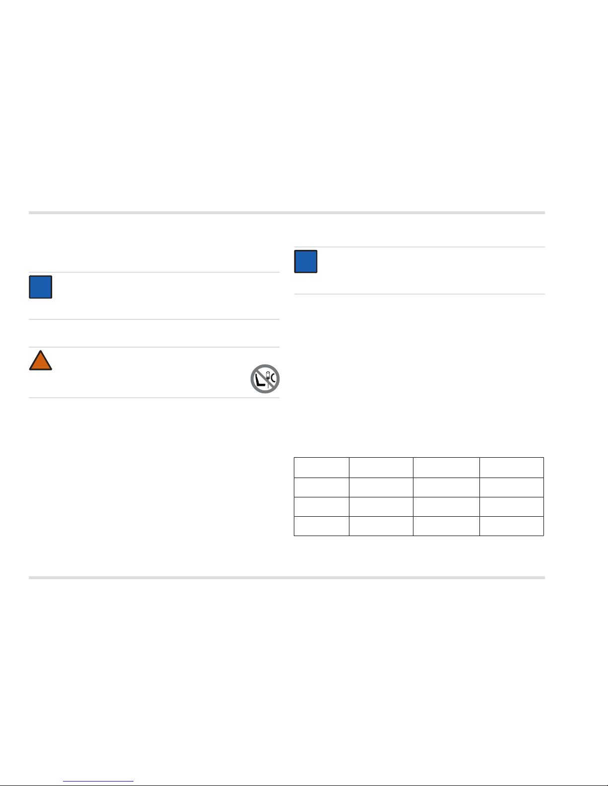
1.3 Bedeutung der Warnzeichen
Die folgenden Warnzeichen werden in diesem Dokument verwendet,
um die zugehörigen Warntexte zu kennzeichnen und hervorzuheben,
die eine erhöhte Aufmerksamkeit seitens des Anwenders erfordern.
Die Bedeutungen der Warnzeichen sind wie folgt definiert:
WARNUNG
Hinweis auf eine potenzielle Gefahrensituation.
Wenn diese nicht vermieden wird, können Tod oder schwere
Verletzungen eintreten.
VORSICHT
Hinweis auf eine potenzielle Gefahrensituation. Wenn diese
nicht vermieden wird, können Verletzungen oder Schädigungen am Produkt oder der Umwelt eintreten. Kann auch als
Warnung vor unsachgemäßem Gebrauch verwendet werden.
HINWEIS
Zusätzliche Information zum Einsatz des Produkts.
!
!
i
i
Page 5
Dräger Interlock 5000/7000 5
Beschreibung
2 Beschreibung
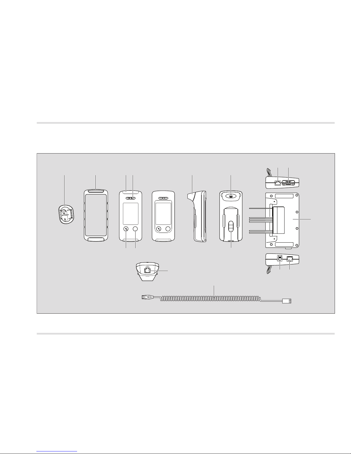
2.1 Produktübersicht
Interlock 5000Interlock 7000
1 2 3 7
8
9
4
5 13
12
11
10
14
6
00133352.eps
15
OK OK
7
Page 6

6 Dräger Interlock 5000/7000
Beschreibung
Legende
1 Halter für Handteil
2 Gehäuseschutz für Handteil (optional)
3 LED
4 Luftauslass
5 Ab/Menü-Taste
6 OK-Taste
7 Mundstück
8 Anschluss Erweiterungsbox
9 Anschluss GPRS-Modul
10 Steuereinheit
11 Buchse für Steckerverbinder des Anschlusskabels
12 Anschluss Kamera
13 IR-Schnittstelle
14 Anschlusskabel Handteil
15 Buchse für Steckerverbinder des Anschlusskabels
2.2 Beschreibung der Anschlussleitungen an der
Steuereinheit
Beschriftung Farbe Beschreibung
1 grau Anschluss zum Anlasserrelais
braun Anschluss "Anlasserrelais" des Zünd-
schalters
2 orange Relais für Anschluss zum Beispiel der
Scheinwerfer (optional)
1)
1) Nur Interlock 7000
violett
3 weiß Relais für Anschluss zum Beispiel der
Hupe (optional)
1)
gelb
4 blau Anschluss "Zündung" des Zündschal-
ters
5 schwarz Masseanschluss
6 rot Plus-Spannungsversorgung
7 weiß Ausgang geschaltet auf PIN 10
8 weiß Ausgang geschaltet auf PIN 10
9 weiß Ausgang geschaltet auf PIN 11 (GND)
10 weiß Spannungsversorgung (für PIN 7 und 8)
11 weiß Masseanschluss (Eingänge/Ausgänge)
12 LED+ weiß Anschluss einer externen LED-Anzeige
(optional)
1)
13 LED- weiß
14 weiß Eingang, auf Masse schaltend
(optional)
15 weiß Eingang, auf “Plus” schaltend
(optional)
16 weiß Eingang, auf “Plus” schaltend
(optional für D+)
Page 7
Dräger Interlock 5000/7000 7
Installation
3 Installation
3.1 Voraussetzungen für die Installation
Das Dräger Interlock 5000/7000
1)
ist für den Einbau in motorgetriebenen Fahrzeugen vorgesehen. Diese können eine Spannungsversorgung von 12 - 24 V haben.
Vor der Installation des Handteils geeigneten Einbauort und Be-
festigungsart zusammen mit dem Besitzer des Fahrzeugs festlegen.
Ist der Stromverbrauch in Bereitschaft (siehe siehe Kapitel 5 auf
Seite 17) für das entsprechende Fahrzeug zu groß, eine Fahrzeugbatterie mit größerer Kapazität verwenden.
Das Gerät ersetzt keine eventuell vorgeschriebene Wegfahrsper-
re gegen Diebstahl.
Installation der Kontrollbox nach fahrzeugspezifischen Vorgaben.
3.2 Installationsmodus
VORSICHT
Falls das Interlock 5000/7000 nach der Installation im Installati-
onsmodus verbleiben soll (Kundenwunsch), beiliegendes Infoblatt
(Bestellnr. 90 33 461) am Rückspiegel anbringen.
3.3 Komponenten vorläufig installieren
Zu Beginn der Installation alle Komponenten vorläufig am vorge-
sehenen Einbauort installieren.
Sicherstellen, dass die Kabel ausreichend lang sind, der Einbauort
geeignet ist und die Installationen bei normaler Nutzung des Fahrzeugs nicht stören.
Sicherstellen, dass die Sicherheit von Fahrzeuginsassen nicht be-
einträchtigt wird.
Einbauort so wählen, dass ausreichend Schutz vor Wasser, Staub
und hohen Temperaturen gewährleistet ist.
3.3.1 Steuereinheit
Steuereinheit möglichst verdeckt installieren, zum Beispiel unter
dem Sitz oder hinter dem Armaturenbrett an der Lenksäule. Befestigung mit Kabelbindern.
VORSICHT
Auf Einhaltung geltender Vorschriften für Installationen in
Fahrzeug-Innenräumen achten!
Veränderungen oder Zusätze an dem Gerät können zu Gefahren führen. Durch solche Veränderungen oder Zusätze
wird die in der Gebrauchsanweisung enthaltene Einbaubescheinigung ungültig.
HINWEIS
Das Gerät nur zur Unterbrechung, bzw. Freigabe der Steuerleitung des Anlasserrelais verwenden.
1) Interlock ist eine eingetragene Marke von Dräger.
!
i
i
Das Gerät wird, je nach Konfiguration, in einem Installationsmodus ausgeliefert. In diesem Modus ist die Wegfahrsperre
des Geräts noch nicht aktiv. Der Motor des Fahrzeugs kann
auch nach der Installation des Geräts ohne Abgabe einer
Atemprobe gestartet werden. Zur Inbetriebnahme des Geräts
ist dieser Modus zu deaktivieren.
HINWEIS
Dauerhafte Installation nur nach Rücksprache mit dem Besitzer des Fahrzeugs.
!
i
i
Page 8
8 Dräger Interlock 5000/7000
Installation
Anschlussleitungen am Kabelbaum der Lenksäule hochziehen
und vorläufig befestigen. Falls die Anschlussleitungen für den Anschluss an den Kabelbaum des Zündschalters zu kurz sind, einen
anderen Einbauort wählen.
3.3.2 Handteil
Befestigungsort für den Halter für das Handteil so vorsehen, dass
das Handteil möglichst wenig stört, aber für den Fahrer leicht zugänglich ist.
Wenn das Kabel von der Steuereinheit zum Halter zu stark ge-
spannt wird oder zu kurz ist, Halter, bzw. Steuereinheit oder beide
an einer anderen Stelle anbringen.
3.4 Leitungen anschließen
3.4.1 Zündleitungen des Fahrzeugs bestimmen
Abdeckung der Lenksäule und Polsterblenden entfernen, um den
Zugang zu Zündschalter und Kabelbaum zu ermöglichen.
Ist die Leitungsführung des Fahrzeugs nicht bekannt, müssen die
entsprechenden Unterlagen über das Fahrzeug herangezogen
werden oder es muss mit Hilfe eines Multimeters oder einer 12 V,
bzw. 24 V-Prüflampe die Lage der Leitungen festgestellt werden:
1. Multimeter auf einen passenden DC-Bereich einstellen.
2. Eine Prüfleitung mit Fahrzeugmasse verbinden, zum Beispiel am
Fahrzeugchassis.
3. Mit der zweiten Prüfleitung die Anschlüsse an der Rückseite des
Zündschalters prüfen und identifizieren:
Zündschalter mit dem Schlüssel durchschalten, um die Spannungsführung bei verschiedenen Schlüsselpositionen zu bestimmen.
HINWEIS
Bei der Installation der Steuereinheit darauf achten, dass das
Anschlusskabel für das Handteil gegen Zugbeanspruchung
gesichert wird (z. B. mit einem Kabelbinder).
WARNUNG
Den Halter des Handteils nicht vor Airbags anbringen.
i
i
!
A
I
R
B
A
G
HINWEIS
Überprüfen, ob fahrzeugspezifische Einbauanweisungen
existieren und ggf. danach verfahren. Eine Liste der vorhandenen Einbauanweisungen ist über Dräger verfügbar.
Schlüsselposi-
tion "START"
Schlüsselposition
"ZÜNDUNG"
Andere Schlüs-
selpositionen
Leitung
Anlasserrelais
Spannung – – – – – –
Leitung
Zündung
Spannung Spannung – – –
Plus-Leitung Spannung Spannung Spannung
i
i
Page 9

Dräger Interlock 5000/7000 9
Installation
3.4.2 Fahrzeugbatterie abklemmen
Vor den weiteren Arbeiten die Masseleitung von der Fahrzeugbat-
terie trennen.
HINWEIS
Manche Fahrzeuge haben zwei Zündungsleitungen, wobei
eine in der Stellung "START" spannungslos ist. Immer die
Zündungsleitung verwenden, die in den Schlüsselpositionen
"START" und "ZÜNDUNG" unter Spannung steht.
HINWEIS
Das Abklemmen der Fahrzeugbatterie löscht eventuell
batterieabhängige Geräteeinstellungen (z. B. den
Diebstahlcode oder die Sendereinstellung des Radios).
Bei einigen Fahrzeugen kann das Abklemmen der
Fahrzeugbatterie zum Aufleuchten der AirbagKontrollleuchte führen, was nur vom Fahrzeughersteller
rückgängig gemacht werden kann.
i
i
i
i
Page 10
10 Dräger Interlock 5000/7000
Installation
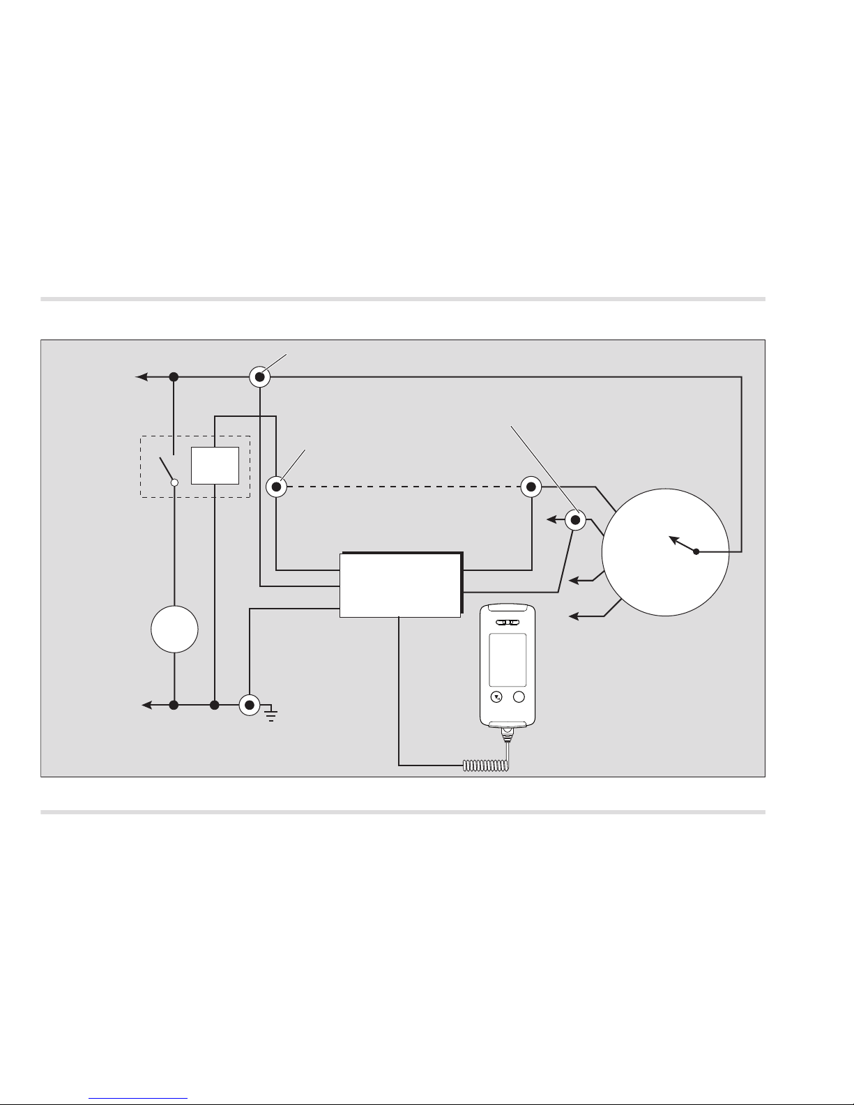
3.4.3 Stromlaufplan
00233352_de.ep
s
Zündschalter
Anlassermotor
Anlasserrelais
Unterbrechung
M
V +
V -
Anlasserrelais
(Klemme 50)
Zündung
(Klemme +15, Position 2)
Zubehör
Aus
Plus
Power
braun grau
rot
schwarz
blau
Masseanschluss
(Klemme 31)
®
Dräger
Interlock 5000/7000
Steuereinheit
®
Dräger Interlock 5000/7000
Handteil
Anlasserrelais-Anschluss
Zündungs-Anschluss
Plus-Anschluss (Klemme 30)
OK
Page 11
Dräger Interlock 5000/7000 11
Installation
3.4.4 Masse-Leitung anschließen
1. Masse-Leitung der Steuereinheit (schwarz) zum Anschluss an die
Fahrzeugmasse vorbereiten.
2. Masse-Leitung mit Hilfe einer Schneidschraube z. B. am Fahrzeugchassis anschließen oder mit einer anderen Masse-Leitung
im Kabelbaum z. B. mit Kabelverbindern verbinden.
3.4.5 Anlasserrelais-Leitung anschließen
1. Anlasserrelais-Leitung im Zündschalter-Kabelbaum so auftrennen, dass eine ausreichende Kabellänge zum Anschluss an die
beiden Leitungen der Steuereinheit vorhanden ist.
2. Anlasserrelais-Anschlussleitungen der Steuereinheit (grau und
braun) bei Bedarf kürzen und wenn nötig abisolieren.
3. Dräger-Schrumpfschlauch auf die Anlasserrelais-Leitung vom
Zündschalter aufstecken.
4. Die Anlasserrelais-Leitung vom Zündschalter-Kabelbaum mit der
grauen Anlasserrelais-Anschlussleitung der Steuereinheit kontaktsicher verbinden.
5. Dräger-Schrumpfschlauch über die Verbindungsstelle schieben
und durch Wärmeeinwirkung aufschrumpfen.
6. Die beiden verbleibenden Anlasserrelais-Leitungen der Steuereinheit und des Kabelbaums ebenfalls in gleicher Weise unter Verwendung des Dräger-Schrumpfschlauches verbinden.
3.4.6 Zündungsleitung anschließen
Das Gerät muss an eine Zündungsleitung des Zündschalters angeschlossen werden, die beim Anlassen des Fahrzeugs (Position
"START" des Zündschalters, siehe Seite 8) und bei eingeschalteter
Zündung (Position "ZÜNDUNG" des Zündschalters, siehe Seite 8) unter Spannung steht.
1. Zündungsleitung im Zündschalter-Kabelbaum so auftrennen, dass
eine ausreichende Kabellänge zum Anschluss an die ZündungsAnschlussleitung (blau) der Steuereinheit vorhanden ist.
2. Zündungs-Anschlussleitung (blau) der Steuereinheit bei Bedarf
kürzen.
3. Dräger-Schrumpfschlauch auf die Zündungs-Anschlussleitung
aufstecken.
4. Zündungs-Anschlussleitung (blau) der Steuereinheit mit den beiden aufgetrennten Enden der Zündungsleitung des Kabelbaums
kontaktsicher verbinden.
5. Dräger-Schrumpfschlauch über die Verbindungsstelle schieben
und durch Wärmeeinwirkung aufschrumpfen.
VORSICHT
Brandgefahr!
Eine saubere und zuverlässige Verbindung zwischen den
Leitungen muss sichergestellt werden!
VORSICHT
Nicht die Leitungen des Fahrzeugs kürzen, damit sie auch
nach dem Ausbau der Steuereinheit wieder benutzt werden
können.
!
!
HINWEIS
Durch den Dräger-Schrumpfschlauch kann eine spätere
Änderung oder Manipulation an der Verbindungsstelle
erkannt werden.
HINWEIS
Durch den Dräger-Schrumpfschlauch kann eine spätere
Änderung oder Manipulation an der Verbindungsstelle
erkannt werden.
i
i
i
i
Page 12

12 Dräger Interlock 5000/7000
Installation
3.4.7 Plus-Leitung anschließen
1. Geeignete Anschlussstelle in der Plus-Leitung (Klemme 30) des
Zündschalter-Kabelbaums auswählen, so dass eine ausreichende
Kabellänge zum Anschluss an die Plus-Anschlussleitung (rot) der
Steuereinheit vorhanden ist.
2. Die Plus-Leitung des Zündschalter-Kabelbaums mit der Plus-Anschlussleitung der Steuereinheit (rot) kontaktsicher verbinden.
3.5 Hupe und Scheinwerfer anschließen (nur
Interlock 7000)
Spezielle Vorschriften können es erforderlich machen, Hupe und/oder
Scheinwerfer an das Gerät anzuschließen. Wenn dies der Fall ist:
1. Schaltart der Hupe, bzw. der Scheinwerfer feststellen:
+12 V/24 V oder Masse.
2. Geeignete Anschlussstellen suchen und Hupe entsprechend dem
Anschlussplan an das Hupen-Relais des Geräts anschließen (Anschlüsse 3, siehe Kapitel 2.2 auf Seite 6), bzw. Scheinwerfer analog an das Scheinwerfer-Relais des Geräts anschließen
(Anschlüsse 2, siehe Kapitel 2.2 auf Seite 6).
Ist die Lage der Fahrzeugsicherung nicht bekannt: eventuell zu-
sätzliche Sicherung in der Zuleitung des Geräts einbauen.
HINWEIS
Manche Fahrzeuge haben Plus-Leitungen, die einige Zeit
nach Abschließen des Fahrzeugs spannungslos geschaltet
werden. Immer eine Plus-Leitung verwenden, die dauernd
Spannung führt, da sich sonst die in der Steuereinheit enthaltene Pufferbatterie entleert.
i
i
Page 13

Dräger Interlock 5000/7000 13
Installation
Anschlussalternative A: Anschlussalternative B:
00333352_de.eps
gelb
+12V/24 V
Hupenschalter
Hupe
weiß
Positiver Schalter
Sicherung (optional)
Sicherung
Dräger
Interlock® 7000
Hupen-Relais
00433352_de.eps
+12V/24 V
Hupenschalter
Hupe
weiß
gelb
Negativer Schalter
Sicherung
Sicherung (optional)
Dräger
Interlock® 7000
Hupen-Relais
Page 14

14 Dräger Interlock 5000/7000
Installation
3.6 Externe Anzeigeleuchte anschließen
In speziellen Fällen (zum Beispiel bei eingeschränktem Hörvermögen)
kann es notwendig sein, eine externe Anzeigeleuchte im direkten
Sichtfeld des Fahrers anzubringen.
1. Geeigneten Montageort auswählen, der für den Fahrer gut sichtbar ist, aber ihn nicht in seiner Sicht behindert (zum Beispiel auf
der Abdeckung der Lenksäule oder über der Instrumententafel).
2. Anzeigeleuchte befestigen und an das Gerät anschließen (Anschlüsse 12 LED+ und 13 LED-, siehe Kapitel 2.2 auf Seite 6).
3.7 Türkontakt anschließen
Es ist möglich, das Gerät (optional) so zu installieren, dass es bereits
durch das Öffnen des Türschlosses oder der Tür aktiviert wird. Dadurch wird die Wartezeit des Fahrers bis zur Betriebsbereitschaft des
Geräts für die Abgabe des Atemalkoholtests verringert.
Das weiße Kabel des Geräts (Anschluss 15, siehe Kapitel 2.2 auf
Seite 6) an einer Leitung des Fahrzeugs anschließen, die beim
Öffnen der Tür mit 12 V, zum Beispiel über die Innenraumbeleuchtung, verbunden wird.
3.8 D+ anschließen (optional)
Es ist möglich, das Gerät so zu installieren, dass das D+ Signal des
Fahrzeuges zur Starterkennung genutzt wird.
Ein Kabel an die Steuereinheit des Geräts (Anschluss 16, siehe
Kapitel 2.2 auf Seite 6) und an die D+ Leitung des Fahrzeuges anschließen.
3.9 Komponenten befestigen
3.9.1 Steuereinheit
1. Steuereinheit mit Kabelbindern an einem Stützelement (zum Beispiel der Lenksäule) befestigen. Dazu Kabelbinder durch die Befestigungslöcher der Steuereinheit ziehen und am Stützelement
befestigen oder Kabelbinder um Steuereinheit und Stützelement
wickeln.
Beispiel:
1 Steuereinheit
2 Kabelbinder
3 Lenksäule
2. Kabel der Steuereinheit möglichst unsichtbar verlegen und befestigen.
3. Spiral-Anschlusskabel zum Handteil an der Steuereinheit einstecken.
4. Verkleidungen wieder montieren.
HINWEIS
Wenn das Interlock an die D+ Leitung des Fahrzeugs angeschlossen werden soll, ist eine entsprechende Änderung der
einstellbaren Parameter des Interlocks nötig. Kontaktieren
Sie bitte vor Anschluss der D+ Leitung ein autorisiertes Dräger-Interlock-Servicezentrum.
i
i
00633352.eps
1
2
3
2
Page 15

Dräger Interlock 5000/7000 15
Installation
3.9.2 Handteil
Zum Befestigen des Handteils im Fahrzeug den zugehörigen Halter
oder das selbstklebende Klettband benutzen. Die Befestigung mit
Klettband wird empfohlen, wenn bei der Befestigung keine Montagespuren hinterlassen werden sollen.
Befestigungsort so wählen, dass das Handteil möglichst wenig
stört, aber für den Fahrer leicht zugänglich ist.
Befestigung des Halters für das Handteil
00733352.eps
Halter mit Schrauben befestigen. Darauf achten, dass die
Befestigungsschrauben immer genügend weit eingeschraubt werden können.
Befestigung mit Klettband
1.
00833352.eps
1
2
2
1
Schutzfolie (1) vom Klettband
abziehen.
2. Mit der selbstklebenden
Rückseite auf einer glatten
Oberfläche des Fahrzeugs
aufkleben (2).
3. 10 bis 15 Sekunden fest andrücken, um eine sichere Befestigung zu gewährleisten..
4. Handteil mit dem Klettband
auf der Rückseite auf dem
montierten Klettband befestigen.
3.10 Funktionsprüfung
1. Nach der Installation die Fahrzeugbatterie wieder anschließen.
2. Funktion des Geräts entsprechend der Gebrauchsanweisung prüfen.
3.11 Einbaubescheinigung
Nach der Installation die in der Gebrauchsanweisung enthaltene
Einbaubescheinigung ausfüllen.
WARNUNG
Den Halter des Handteils nicht vor Airbags
anbringen.
!
A
I
R
B
A
G
HINWEIS
Die klebende Befestigung ist nach ca. 36 Stunden vollständig
belastbar. Befestigung vorher nicht belasten.
i
i
Page 16

16 Dräger Interlock 5000/7000
Entsorgung
3.12 Geräteeinstellung und Kalibrierung
Diese Arbeiten dürfen nur von einem autorisierten Dräger-InterlockServicezentrum durchgeführt werden.
Bei Bedarf die variablen Geräteeinstellungen des Geräts einstel-
len.
Gerät kalibrieren, falls notwendig.
3.13 Interlock 5000/7000 ausbauen
3.13.1 Fahrzeugbatterie abklemmen
Vor den Arbeiten die Masseleitung von der Fahrzeugbatterie tren-
nen.
3.13.2 Anschlussleitungen trennen
1. Die Plus- (rot), Masse- (schwarz), Zündungs- (blau) und Türkontakt-Leitung (weiß) der Steuereinheit vom Kabelbaum des Fahrzeugs trennen.
2. Gegebenenfalls auch die Hupe-, Scheinwerfer- und D+ Leitungen
der Steuereinheit vom Kabelbaum des Fahrzeugs trennen.
3. Offene Leitungen des Kabelbaums gegen Kurzschluss und Korrosion mit hochwertigem Isolierband oder Schrumpfschlauch schützen.
4. Anlasserrelais-Leitungen der Steuereinheit (grau und braun) vom
Kabelbaum des Fahrzeugs trennen und die beiden AnlasserrelaisLeitungen des Kabelbaums durch Löten verbinden.
5. Die Verbindung gegen Kurzschluss und Korrosion schützen, z. B.
mit einem Schrumpfschlauch.
6. Nach dem Ausbau des Geräts die Fahrzeugbatterie wieder anschließen.
4 Entsorgung
Produkt gemäß den geltenden Vorschriften entsorgen.
4.1 Entsorgungshinweise
HINWEIS
Das Abklemmen der Fahrzeugbatterie löscht eventuell
batterieabhängige Geräteeinstellungen (z. B. den
Diebstahlcode oder die Sendereinstellung des Radios).
Bei einigen Fahrzeugen kann das Abklemmen der
Fahrzeugbatterie zum Aufleuchten der AirbagKontrollleuchte führen, was nur vom Fahrzeughersteller
rückgängig gemacht werden kann.
i
i
Gemäß Richtlinie 2002/96/EG darf dieses Produkt nicht als
Siedlungsabfall entsorgt werden. Es ist daher mit dem nebenstehenden Symbol gekennzeichnet.
Dräger nimmt dieses Produkt kostenlos zurück. Informationen dazu geben die nationalen Vertriebsorganisationen und
Dräger.
Page 17

Dräger Interlock 5000/7000 17
Technische Daten
5 Technische Daten
Messprinzip Elektrochemischer DrägerSensor
Messbereich bis 2,50 mg/L
Umgebungsbedingungen
bei Betrieb und Lagerung –45 °C bis 85 °C
20 % bis 98 % r. F.
600 bis 1100 hPa
Kein Einfluss von Höhenänderungen
auf das Messergebnis
Drift der Empfindlichkeit typisch 1 % vom Messwert / Monat
Anzeige Display
Kalibrierintervall typisch 12 Monate
Abmessungen (H x B x T)
Handteil ca. 140 mm x 60 mm x 36 mm
Steuereinheit ca. 150 mm x 90 mm x 32 mm
Gewicht
Handteil Interlock 5000 ca. 170 g
Handteil Interlock 7000 ca. 180 g
Steuereinheit ca. 195 g
Spannungsversorgung 12 V bis 24 V
Stromverbrauch
maximal <2,5 A
in Bereitschaft <1 mA
Schaltrelais für die Leitung
des Anlasserrelais
<16 A, kontinuierlich
<40 A, Spitze
Ausgangsrelais
schaltbar stromlos 48 V
schaltbar strombelastet 24 V
Leitung Zündung 5 V bis 48 V
Wartezeit für Messbereitschaft
Interlock 5000 Interlock 7000
20 °C 7 s2 s
0 °C 15 s<5 s
-25 °C <60 s <60 s
-45 °C <115 s110 s
Page 18

18 Dräger Interlock 5000/7000
Bestellliste
6 Bestellliste
Bestellnr.
83 22 550
83 22 570
83 22 597
83 22 414
83 22 417
83 22 416
83 22 418
44 11 525
83 22 497
83 15 909
83 20 248
83 22 618
83 22 619
Benennung und Beschreibung
Dräger Interlock 5000
Atemalkoholgesteuerte W
egfahrsperre (Handteil
und Steuereinheit) zum Einbau in Kraftfahrzeuge,
12 V bis 24 V, Mundstücke (3 Stück) und Montagezubehör
Dräger Interlock 7000
Atemalkoholgesteuerte Wegfahrsperre (Handteil
und Steuereinheit) zum Einbau in Kraftfahrzeuge,
12 V bis 24 V, Mundstücke (3 Stück) und Montagezubehör
Mundstücke (300 Stück), einzeln verpackt
Kabelsatz, Standard
Kabelsatz zum Anschluss von Hupe und Scheinwerfer
Kabelsatz zum Anschluss von Hupe
Kabelsatz zum Anschluss von externen Geräten
(AUX/OUT)
Externe LED-Anzeige
Halter für Handteil
Spiralkabel, Länge 1,5 m
Spiralkabel, Länge 5,5 m
Interlock 7000 Kamera Klebepad, (10 Stück)
Interlock 7000 GPRS-Antenne Klebepads,
(10 Stück)
Page 19

Dräger Interlock 5000/7000 19
Content
Content
1 For your safety . . . . . . . . . . . . . . . . . . . . . . . . . . . . . . . . 20
1.1 General safety statements . . . . . . . . . . . . . . . . . . . . . . . . 20
1.2 Installation . . . . . . . . . . . . . . . . . . . . . . . . . . . . . . . . . . . . .20
1.3 Definitions of alert icons . . . . . . . . . . . . . . . . . . . . . . . . . .20
2 Description. . . . . . . . . . . . . . . . . . . . . . . . . . . . . . . . . . . . 21
2.1 Product overview. . . . . . . . . . . . . . . . . . . . . . . . . . . . . . . . 21
2.2 Description of the connection leads on the control unit. . . 22
3 Installation . . . . . . . . . . . . . . . . . . . . . . . . . . . . . . . . . . . . 23
3.1 Requirements for installation. . . . . . . . . . . . . . . . . . . . . . . 23
3.2 Installation mode . . . . . . . . . . . . . . . . . . . . . . . . . . . . . . . .23
3.3 Preliminary installation of components . . . . . . . . . . . . . . . 23
3.3.1 Control unit . . . . . . . . . . . . . . . . . . . . . . . . . . . . . . . . . . . . 23
3.3.2 Handset . . . . . . . . . . . . . . . . . . . . . . . . . . . . . . . . . . . . . . . 24
3.4 Connecting the leads. . . . . . . . . . . . . . . . . . . . . . . . . . . . . 24
3.4.1 Tracing the vehicle ignition wires . . . . . . . . . . . . . . . . . . . 24
3.4.2 Disconnecting the vehicle battery . . . . . . . . . . . . . . . . . . . 25
3.4.3 Circuit diagram . . . . . . . . . . . . . . . . . . . . . . . . . . . . . . . . .26
3.4.4 Connecting the earth lead . . . . . . . . . . . . . . . . . . . . . . . . .27
3.4.5 Connecting starter relay lead . . . . . . . . . . . . . . . . . . . . . . 27
3.4.6 Connecting the ignition lead . . . . . . . . . . . . . . . . . . . . . . . 27
3.4.7 Connecting the positive supply lead . . . . . . . . . . . . . . . . . 28
3.5 Connecting the horn and headlights (only Interlock 7000) 28
3.6 Connecting the external indicator light . . . . . . . . . . . . . . .30
3.7 Connecting the door contact . . . . . . . . . . . . . . . . . . . . . . . 30
3.8 Connect D+ (optional) . . . . . . . . . . . . . . . . . . . . . . . . . . . . 30
3.9 Fixing the components . . . . . . . . . . . . . . . . . . . . . . . . . . .30
3.9.1 Control unit . . . . . . . . . . . . . . . . . . . . . . . . . . . . . . . . . . . . 30
3.9.2 Handset . . . . . . . . . . . . . . . . . . . . . . . . . . . . . . . . . . . . . . . 31
3.10 Functional test . . . . . . . . . . . . . . . . . . . . . . . . . . . . . . . . . . 31
3.11 Installation certificate . . . . . . . . . . . . . . . . . . . . . . . . . . . . 31
3.12 Instrument setting and calibration. . . . . . . . . . . . . . . . . . . 32
3.13 Removing the Interlock 5000/7000 . . . . . . . . . . . . . . . . . . 32
3.13.1 Disconnecting the vehicle battery . . . . . . . . . . . . . . . . . . . 32
3.13.2 Detaching the connecting leads . . . . . . . . . . . . . . . . . . . . 32
4 Disposal. . . . . . . . . . . . . . . . . . . . . . . . . . . . . . . . . . . . . . 32
4.1 WEEE . . . . . . . . . . . . . . . . . . . . . . . . . . . . . . . . . . . . . . . . 32
5 Technical data. . . . . . . . . . . . . . . . . . . . . . . . . . . . . . . . . 33
6 Order list . . . . . . . . . . . . . . . . . . . . . . . . . . . . . . . . . . . . . 34
Page 20

20 Dräger Interlock 5000/7000
For your safety
1 For your safety
1.1 General safety statements
Before using this product, carefully read the associated Instructions for
Use. This document does not replace the Instructions for Use.
1.2 Installation
Installation may only be carried out by an authorized Dräger-Interlock
®
service centre or a professional auto repair shop according to these
assembly instructions.
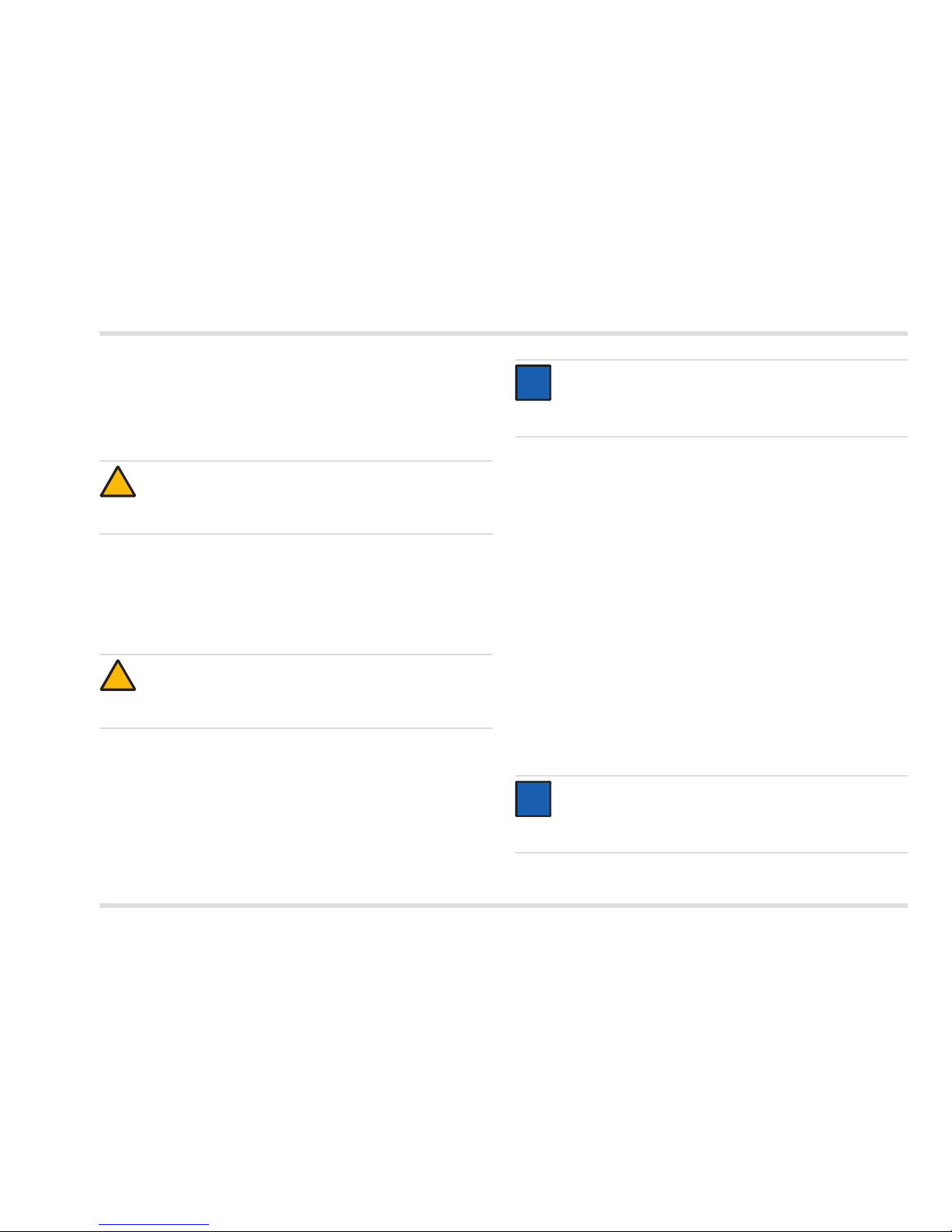
1.3 Definitions of alert icons
The following alert icons are used in this document to indicate and
highlight areas of the associated text that require a greater awareness
by the user. A definition of the meaning of each icon is as follows:
WARNING
Indicates a potentially hazardous situation.
If this is not avoided, death or serious injury may result.
CAUTION
Indicates a potentially hazardous situation. If this is not avoided,
injuries or damage to the product or the environment may occur.
It may also be used to alert against unsafe practices.
NOTICE
Indicates additional information on how to use the product.
!
!
i
i
Page 21

Dräger Interlock 5000/7000 21
Description
2 Description
2.1 Product overview
Interlock 5000Interlock 7000
1 2 3 7
8
9
4
5 13
12
11
10
14
6
00133352.eps
15
OK OK
7
Page 22

22 Dräger Interlock 5000/7000
Description
Legend
1 Holster for handset
2 Protective case for handset (optional)
3 LED
4 Air outlet
5 Down/Menu button
6 OK button
7 Mouthpiece
8 Expansion box connection
9 GPRS module connection
10 Control unit
11 Socket for plug connector on connection cable
12 Camera connection
13 IR interface
14 Handset connection cable
15 Socket for plug connector on connection cable
2.2 Description of the connection leads on
the control unit
Label Colour Description
1 grey Connection to starter relay
brown "Starter relay" connection on the ignition
switch
2 orange Relay for connection, such as for
headlights (optional)
1)
1) Only Interlock 7000
purple
3 white Relay for connection, such as for horn
(optional)
1)
yellow
4 blue "Ignition" connection of the ignition
switch
5 black Earth
6 red Positive power supply
7 white Output switched to PIN 10
8 white Output switched to PIN 10
9 white Output switched to PIN 11 (GND)
10 white Power supply (for PINs 7 and 8)
11 white Earth connection (inputs/outputs)
12 LED+ white External LED display connection
(optional)
1)
13 LED– white
14 white Input, switching to earth
(optional)
15 white Input, switching to positive
(optional)
16 white Input, switching to positive
(optional for D+)
Page 23

Dräger Interlock 5000/7000 23
Installation
3 Installation
3.1 Requirements for installation
The Dräger Interlock 5000/7000
1)
is intended for installation into
motorized vehicles. These can have a power supply voltage of
12 – 24 V.
Prior to installing the handset, please decide upon a suitable
mounting location and method together with the owner of the
vehicle.
If the stand-by current consumption (see see Chapter 5 on
page 33) is too high for the respective vehicle, use a vehicle
battery with higher capacity.
The instrument is not a substitute for a vehicle immobilizer for theft
protection.
Install the control box in line with vehicle-specific stipulations.
3.2 Installation mode
CAUTION
If the Interlock 5000/7000 is to remain in the installation mode after
installation (customer request), attach the enclosed information
sheet (order no. 90 33 461) to the rearview mirror.
3.3 Preliminary installation of components
To begin the installation process, install all components temporarily
at their intended positions.
Ensure adequate cable lengths as well as suitability of positions
and that the installation does not obstruct normal use of the
vehicle.
Ensure that the safety of passengers is not impaired.
Choose position where sufficient protection against water, dust and
high temperatures is ensured.
3.3.1 Control unit
Install control unit in as hidden a position as possible, such as
under the seat or front dash on the steering column. Fix with
cable ties.
CAUTION
Observe the existing regulations for installations in the interior
of vehicles.
Alterations and additions to the device may cause dangers.
Such alterations and additions invalidate the certificate of
installation contained in the instructions for use.
NOTICE
Install the device only for interruption and connection to
the starter relay control lead.
1) Interlock is a registered trademark of Dräger.
!
i
i
The device is supplied in an installation mode, depending on
configuration. In this mode, the device immobilizer is not yet
enabled. The vehicle's engine can be started after the unit is
installed without a breath sample being given. This mode
should be deactivated when commissioning the device.
NOTICE
Only install the device permanently following consultation
with the owner of the vehicle.
!
i
i
Page 24

24 Dräger Interlock 5000/7000
Installation
Draw connecting leads up along steering column cable harness and
temporarily secure in place. If leads are too short for connection to the
ignition switch cable harness, re-position the control unit.
3.3.2 Handset
Decide upon mounting location for the holster for the handset
ensuring minimal obstruction by the handset and easy accessibility
for the driver.
If the cable from the control unit to the handset is too tightly
stretched or too short, re-position the handset, the control unit
or both.
3.4 Connecting the leads
3.4.1 Tracing the vehicle ignition wires
Detach the steering column cover and padded screens to access
the ignition switch and cable harness.
If the vehicle wiring is unknown, the relevant documents on the
vehicle must be consulted or the circuits will have to be traced
using a multimeter or a 12 V or 24 V test light:
1. Switch multimeter to an appropriate DC measuring range.
2. Connect one lead to vehicle earth, for example onto the vehicle
chassis.
3. Test and identify the connections at the back of the ignition switch
with the second test lead:
switch the ignition switch slowly on to trace the voltage at different
key positions.
NOTICE
When installing the control unit, ensure that the
connection cable for the handset is secured against
tensile load (e. g. using a cable tie).
WARNING
Do not install holster for the handset in front of
airbags.
i
i
!
A
I
R
B
A
G
NOTICE
Check for any installation instructions specific to the vehicle,
and if these exist, continue by following those instructions.
A list of available installation instructions can be obtained
from Dräger.
"START"
key position
"IGNITION"
key position
Other
key positions
Lead
starter relay
Voltage – – – – – –
Lead
ignition
Voltage Voltage – – –
Positive
supply lead
Voltage Voltage Voltage
i
i
Page 25

Dräger Interlock 5000/7000 25
Installation
3.4.2 Disconnecting the vehicle battery
Disconnect battery earth lead before further work.
NOTICE
Some vehicles have two ignition leads where one is without
voltage in key position "START". Always use the ignition lead
that is under voltage in key positions "START" and "IGNITION".
NOTICE
Disconnecting the vehicle battery may erase batterydependent instrument settings (e. g. the theft code for
the radio or the preset stations). On some vehicles,
disconnecting the vehicle battery may turn the airbag light on,
which can then only be turned off by the vehicle manufacturer.
i
i
i
i
Page 26

26 Dräger Interlock 5000/7000
Installation
3.4.3 Circuit diagram
00233352_en.ep
s
Ignition switch
Starter motor
Starter relay
Break
M
V +
V -
Starter relay
(Terminal 50)
Ignition
(Terminal +15, Position 2)
Accessories
Off
Plus
Power
brown grey
red
black
blue
Ground termination
(Terminal 31)
®
Dräger
Interlock 5000/7000
Control box
®
Dräger Interlock 5000/7000
Handset
Starter relay termination
Ignition termination
Positive supply termination (Terminal 30)
OK
M
Page 27

Dräger Interlock 5000/7000 27
Installation
3.4.4 Connecting the earth lead
1. Prepare earth lead of the control unit (black) for connection with
vehicle earth.
2. Connect earth lead using a self-tapping screw, e. g. to the vehicle
chassis, using another earth wire in the cable harness, for example
with a solder connection.
3.4.5 Connecting starter relay lead
1. Cut starter relay lead in the ignition-switch cable harness ensuring
adequate cable has been left for termination on both leads of the
control unit.
2. Trim, as necessary, both starter relay leads on the control unit
(grey and brown) and strip.
3. Put Dräger thermo-shrinkable tubing on the starter relay lead from
the ignition switch.
4. Connect the starter relay lead from the ignition switch cable
harness to the grey starter relay connecting cable on the control
unit to ensure correct contact.
5. Push Dräger thermo-shrinkable tubing over the joint and shrink by
heat application.
6. Connect the two remaining starter relay lines of the control unit
and the cable harness in the same way using the Dräger shrink
tubing.
3.4.6 Connecting the ignition lead
The instrument must be connected to an ignition lead of the ignition
switch that remains live when the vehicle is started up (position
"START" of the ignition switch, see page 24) and when the ignition is
switched on (position "IGNITION" of the ignition switch, see page 24).
1. Cut ignition lead in the ignition-switch cable harness ensuring
adequate cable has been left for termination on the ignition lead (blue)
on the control unit.
2. Trim, as necessary, ignition lead on the control unit (blue).
3. Place Dräger thermo-shrinkable tubing on the ignition lead.
4. Join the control unit ignition cable (blue) to the two separated ends
of the cable harness ignition wire to ensure reliable contact.
5. Push Dräger thermo-shrinkable tubing over the joint and shrink by
heat application.
CAUTION
Fire hazard!
A clean and reliable connection between the leads must be
ensured!
CAUTION
Do not trim the wires of the vehicle so that they can be used
again after deinstallation of the control unit.
!
!
NOTICE
The Dräger thermo-shrinkable tubing means that any future
change or manipulation of the joint can be detected.
NOTICE
The Dräger thermo-shrinkable tubing means that any future
change or manipulation of the joint can be detected.
i
i
i
i
Page 28

28 Dräger Interlock 5000/7000
Installation
3.4.7 Connecting the positive supply lead
1. Locate suitable connection position in the positive supply lead
(terminal 30) of the ignition-switch cable harness ensuring
adequate cable has been left for termination of the positive supply
lead (red) on the control unit.
2. Connect the positive lead from the ignition switch cable harness to
the positive connecting cable on the control unit (red) to ensure
correct contact.
3.5 Connecting the horn and headlights
(only Interlock 7000)
Special regulations may require the device to be connected to the horn
and/or the headlights. If this is the case:
1. Determine the activation method of horn and/or headlights as
appropriate:
+12 V/24 V or earth.
2. Locate suitable connection positions and connect horn according
to the connection scheme to the horn relay of the device
(connections 3, see Chapter 2.2 on page 22), or connect
headlights in the same way as appropriate to the headlight relay
on the device (connections 2, see Chapter 2.2 on page 22).
If the position of the vehicle fuse is not known: install an additional
fuse in the input cable of the instrument, if required.
NOTICE
Some vehicles have positive wires whose current is switched
off some time after the vehicle is locked. Always use a positive
wire which is constantly under voltage, as otherwise the buffer
battery in the control unit will be drained.
i
i
Page 29

Dräger Interlock 5000/7000 29
Installation
Connection alternative A: Connection alternative B:
00333352_en.eps
yellow
+12V/24 V
Horn switch
Horn
white
Positive switch
Fuse (optional)
Fuse
Dräger
Interlock® 5000/7000
Horn relay
00433352_en.eps
Dräger
Interlock® 5000/7000
Horn relay
+12V/24 V
Horn switch
Horn
white
yellow
Negative switch
Fuse
Fuse (optional)
Page 30

30 Dräger Interlock 5000/7000
Installation
3.6 Connecting the external indicator light
In special cases (for example with restricted aural capability) it may be
necessary to install an external indicator light in the area directly visible
to the driver.
1. Locate suitable mounting position directly visible to the driver but
not hindering the driver (for example on top of the cover of the
steering column or above the instrument panel).
2. Mount indicator lights and connect to the device (connections 12
LED+ and 13 LED–, see Chapter 2.2 on page 22).
3.7 Connecting the door contact
It is possible (optional) to install the device in such a way that it is
activated by opening the door lock or the door alone. This reduces the
waiting time for the driver until the device is ready for operation and for
the driver to provide a breath alcohol test.
Connect the white cable on the device (connection 15, see
Chapter 2.2 on page 22) to a lead on the vehicle that is connected
to 12 V when the door opens, for example the internal light.
3.8 Connect D+ (optional)
It is possible to install the device so that the vehicle's D+ signal is used
to detect start-up.
Connect a cable to the device control unit (connection 16, see Chapter 2.2
on page 22) and to the D+ vehicle lead.
3.9 Fixing the components
3.9.1 Control unit
1. Secure the control unit with cable ties onto a support (such as the
steering column). Thread the cable ties through the tabs of the
control unit and secure onto the support or wrap the cable ties
around both the support and the steering column.
Example:
1 Control unit
2 Cable ties
3 Steering column
2. Secure cables from the control unit; where possible, lay cables out
of sight.
3. Plug in spiral connection cord for handset into the control unit.
4. Re-fit covers on the steering column.
NOTICE
If the Interlock unit is to be connected to the vehicle's D+ line
then it is necessary to change the corresponding parameter
on the Interlock. Before connecting the D+ lead, please
contact an authorized Dräger Interlock service centre.
i
i
00633352.eps
1
2
3
2
Page 31

Dräger Interlock 5000/7000 31
Installation
3.9.2 Handset
To mount the handset in the vehicle, use the dedicated holster or the
self-fixing Velcro tape. Fixing with the Velcro tape is the preferred
option in situations where it is desirable for no mounting marks to
be left.
Decide upon mounting location ensuring minimal obstruction by
the handset and easy accessibility for the driver.
Fixing the holster for the handset
00733352.eps
Fix holster with screws. Ensure
adequate clearance behind
fixing screws so that they can
be screwed in far enough.
Fixing with Velcro tape
1.
00833352.eps
1
2
2
1
Remove self-adhesive
backing (1) of the hook-andloop tape.
2. Using the self-adhesive
backing, stick onto a smooth
surface in the vehicle (2).
3. Apply firm pressure for
10 to 15 seconds for secure
adhesion.
4. Fix handset with the Velcro
tape on the reverse side onto
the mounted Velcro tape.
3.10 Functional test
1. After installation, reconnect the vehicle battery.
2. Test the function of the device in line with the instructions for use.
3.11 Installation certificate
After installation, complete the installation certificate contained in
the instructions for use.
WARNING
Do not install holster for the handset in front
of airbags.
!
A
I
R
B
A
G
NOTICE
The adhesive mounting is fully attached after approx.
36 hours. Do not load mounting before this time.
i
i
Page 32

32 Dräger Interlock 5000/7000
Disposal
3.12 Instrument setting and calibration
This work is only permitted to be carried out by an authorized DrägerInterlock service centre.
If required, set the variable device settings on the device.
Calibrate the device, if necessary.
3.13 Removing the Interlock 5000/7000
3.13.1 Disconnecting the vehicle battery
Disconnect the earth lead from the vehicle battery before doing
any work.
3.13.2 Detaching the connecting leads
1. Detach the positive lead (red), earth lead (black), ignition lead (blue),
and the door contact lead (white) on the control unit from the cable
harness of the vehicle.
2. If required, also disconnect the control unit's horn, headlights and
D+ lines from the vehicle's cable harness.
3. Protect open leads of the cable harness against short circuit and
corrosion with high-quality insulating tape or thermo shrinkable
tubing.
4. Disconnect the control unit's starter relay lines (grey and brown)
from the vehicle's cable harness and join the two starter relay lines
of the cable harness via soldering.
5. Protect the connection against short-circuit and corrosion,
e. g. using a thermo-shrinkable tubing.
6. After removing the device, re-connect the vehicle battery.
4 Disposal
Dispose of the product in accordance with the applicable rules and
regulations.
4.1 WEEE
NOTICE
Disconnecting the vehicle battery may erase battery-dependent
instrument settings (e. g. the theft code for the radio or the preset
stations). On some vehicles, disconnecting the vehicle battery
may turn the airbag light on, which can then only be turned off by
the vehicle manufacturer.
i
i
In accordance with EU Directive 2002/96/EC this product
must not be disposed of as household waste. This is indicated
by the adjacent icon.
You can return this product to Dräger free of charge.
For information please contact the national marketing
organizations and Dräger.
Page 33

Dräger Interlock 5000/7000 33
Technical data
5 Technical data
Measuring principle Electrochemical DrägerSensor
Measuring range up to 2.50 mg/l
Ambient conditions
for operation and storage –45 °C to 85 °C
20 % to 98 % r. h.
600 to 1100 hPa
No influence of changes in altitude on
the measurement result
Sensitivity drift Typically 1 % of measured value /
month
Display Display
Calibration interval Typically 12 months
Dimensions (H x W x D)
Handset approx. 140 mm x 60 mm x 36 mm
Control unit approx. 150 mm x 90 mm x 32 mm
Weight
Interlock 5000 handset approx. 170 g
Interlock 7000 handset approx. 180 g
Control unit approx. 195 g
Voltage supply 12 V to 24 V
Power consumption
maximum <2.5 A
stand-by <1 mA
Switch relay for the lead
for the starter relay
<16 A, continuous
<40 A, peak
Output relay
switchable de-energized 48 V
switchable energized 24 V
Ignition lead 5 V to 48 V
Waiting time to be ready for
measurement
Interlock 5000 Interlock 7000
20 °C 7 s2 s
0 °C 15 s<5 s
–25 °C <60 s <60 s
–45 °C <115 s110 s
Page 34

34 Dräger Interlock 5000/7000
Order list
6 Order list
Order no.
83 22 550
83 22 570
83 22 597
83 22 414
83 22 417
83 22 416
83 22 418
44 11 525
83 22 497
83 15 909
83 20 248
83 22 618
83 22 619
Name and description
Dräger Interlock 5000
Breath alcohol controlled vehicle immobilizer
(handset and control unit) for installation in motor
vehicles, 12 V to 24 V
, mouthpieces (3 pieces) and
mounting accessories
Dräger Interlock 7000
Breath alcohol controlled vehicle immobilizer
(handset and control unit) for installation in motor
vehicles, 12 V to 24 V, mouthpieces (3 pieces) and
mounting accessories
Mouthpieces (300 pieces), individually packaged
Cable set, standard
Cable set for connecting horn and headlights
Cable set for connecting horn
Cable set for connecting external equipment
(AUX/OUT)
External LED display
Holster for handset
Spiral cord, length 1.5 m
Spiral cord, length 5.5 m
Interlock 7000 camera adhesive pad (10 pieces)
Interlock 7000 GPRS antenna adhesive pads,
(10 pieces)
Page 35

Page 36

90 33 352 - MA 4754.350
© Dräger Safety AG & Co. KGaA
Edition 02 - June 2013 (Edition 01 - October 2012)
Subject to alteration
Dräger Safety AG & Co. KGaA
Revalstraße 1
23560 Lübeck, Germany
Tel +49 451 882-0
Fax +49 451 882-20 80
www.draeger.com
 Loading...