

Page 1
Instructions for Use
Infinity Delta Series
WARNING
To properly use this medical device, the
user must obtain a full understanding of
the performance characteristics of this
medical device prior to use by carefully
reading these Instructions for Use.
Infinity Patient Monitoring Series
Software VF8
Page 2

Manufactured by:
Draeger Medical Systems, Inc.
3135 Quarry Road
Telford, PA 18969-1042
Infinity Delta Series Instructions for Use
Software VF8
©Draeger Medical Systems, Inc.2010.
All rights reserved.
Printed in the United States of America.
This device bears the CE label in
accordance with the provisions of the
Directive 93/42/EEC of 14 June 1993
concerning medical devices (this label is
not applicable for US devices).
Distributed By:
Dräger Medical GmbH
Moislinger Alee 53-55
D-23558 Lübeck
Germany
Reproduction in any manner, in whole or in part, in
English or in any other languages, except for brief
excerpts in reviews and scientific papers, is prohibited
without prior written permission of Dräger Medical
GmbH.
All Dräger devices are intended for use by trained
medical personnel only.
Before using any Dräger devices, carefully read all the
manuals that are provided with your device. Patient
monitoring equipment, however sophisticated, should
never be used as a substitute for the human care,
attention, and critical judgment that only trained health
care professionals can provide.
ACE, MultiMed, Hemo2, Hemo4, Infinity, SmartPod,
Trident, Pick and Go, Scio, MicrO2+, and OxiSure are
registered trademarks of Dräger Medical GmbH.
PiCCO, PULSION, and PULSIOCATH are registered
trademarks of PULSION Medical Systems AG
CAPNOSTAT is a registered trademark of Novametrix
Medical Systems, Inc.
BIS and Bispectral Index are trademarks of Aspect
Medical Systems, Inc. and are registered in the USA, EU,
and other countries.
A-2000 and BISx are trademarks of Aspect Medical
Systems, Inc.
The Infinity BISx pod bears the CE label
in accordance with the provisions of the
Directive 93/42/EEC of 14 June 1993
concerning medical devices (this label is
not applicable for US devices).
The Infinity BISx pod is manufactured by:
Covidien
15 Hampshire St.
Mansfield, MA 02048
USA
Authorized EC representative:
Covidien Ireland Limited
IDA Business & technology Park
Tullamore, Ireland
Masimo, Masimo SET and Signal Extraction Technology
(SET) are registered trademarks of Masimo Corporation.
Nellcor is a registered trademark of Covidien
SILICON SOFTWARE © 1989, 90, 91, 92, 93, 94
Microtec Research Inc.
All rights reserved
Some graphics courtesy of Novametrix Medical Systems,
Inc.
Unpublished rights reserved under the copyright laws of
the United States.
RESTRICTED RIGHTS LEGEND Use duplication or
disclosure by the Government is subject to restrictions as
set forth in subparagraph (c)(1)(ii) of the Rights in
Technical Data & Computer Software clause at DFARS
252 227:7013
The Infinity etCO
bears the CE label in accordance with
the provisions of the Directive
93/42/EEC of 14 June 1993 concerning
medical devices.
The Infinity etCO
manufactured by:
Oridion Medical 1987 Ltd.
P.O. Box 45025
HaMarpe 7, Har-Hozvim
91450 Jerusalem
Israel
Authorized EC representative:
Obelis S. A.
Av. de Tevuren, 34 Bte 44
B-1040 Brussels
Belgium
Microstream is a registered trademark of Oridion Medical
2 Microstream pod
2 Microstream pod is
1987 Ltd.
All other brand or product names are trademarks or
registered trademarks of their respective companies.
2 Instructions for Use Delta/Delta XL/Kappa VF8
Page 3

Overview
Intended Use ..................................................................................................................... 4
Indications for Use ........................................................................................................... 4
Intended Patient Categories ............................................................................................ 5
Documentation Features.................................................................................................. 5
Warnings, Cautions, Notes ....................................................................................5
Cross-references........................................................................................................5
Quick Reference Tables ............................................................................................5
Footer ..........................................................................................................................5
Applicability ................................................................................................................ 6
Safety Considerations...................................................................................................... 6
Site of Operation ........................................................................................................ 7
Inspection and Maintenance ..................................................................................... 8
Defibrillator Precautions .........................................................................................10
Pacemakers ..............................................................................................................11
Peripheral Devices ...................................................................................................11
Electrosurgery..........................................................................................................11
Electromagnetic Compatibility ......................................................................................13
Table of Contents ...........................................................................................................14
Page 4

I
NFINITY DELTA SERIES USER’S GUIDE
Intended Use
The Infinity Delta Series (Delta/Delta XL/Kappa) Monitors are intended for multiparameter patient monitoring. The devices will produce visual and audible alarms if
any of the physiological parameters monitored vary beyond preset limits and timed or
alarm recordings will be produced. This device will connect to an R50 recorder, either
directly or via the Infinity Network.
NOTE: All Dräger hardware and screen shots shown in these Instructions for Use are
examples only. Actual product or screens may differ slightly.
Indications for Use
The Infinity Delta series monitors are capable of monitoring:
Heart rate
Respiration rate
Invasive pressure
Non-invasive pressure
Arrhythmia
Temperature
Cardiac output
Arterial oxygen saturation
Pulse rate
Apnea
ST segment analysis
12-lead ST segment analysis
tcpO2/tcpCO2
EEG signals
FiO
etCO
Respiratory mechanics
Anesthetic agents
Neuromuscular transmission
2
2
4DELTA/DELTA XL/KAPPA VF8
Page 5

INFINITY DELTA SERIES USER’S GUIDE
The devices are intended to be used in the environment where patient care is provided
by healthcare professionals, i.e. physicians, nurses, and technicians, who will
determine when use of the device is indicated, based on their professional assessment
of the patient’s medical condition.
Intended Patient Categories
The Infinity Delta Series (Delta/Delta XL/Kappa) monitors are intended to be used on
adult, pediatric, and neonatal populations, with the exception of the parameter Cardiac
Output, ST Segment Analysis, and arrhythmia which are intended for use in the adult
and pediatric populations only; and tcpO
only be used when the patient is not under gas anesthesia.
, which for the neonatal population, is to
2
Documentation Features
Warnings, Cautions, Notes
WARNING! A WARNING statement provides important
information about a potentially hazardous situation which, if
not avoided, could result in death or serious injury.
CAUTION! A CAUTION statement provides important information about a potentially
hazardous situation which, if not avoided may result in minor or moderate injury to the
user or patient, or in damage to the equipment or other property.
NOTE: A note provides additional information intended to avoid inconvenience
during operation.
Cross-references
Cross-references specify chapter and page (for example, page 16-3 refers to chapter
16, page 3). The chapter number is given when text refers to an entire chapter (for
example, chapter 1).
Quick Reference Tables
Wherever possible, a quick reference table is provided for easy access to information
about monitor functions.
VF8 DELTA/DELTA XL/KAPPA 5
Page 6

I
NFINITY DELTA SERIES USER’S GUIDE
Footer
The current software version appears at the bottom of each page, together with the
chapter and page number and the device name.
Applicability
All references to “the monitor” in this manual refer to the Delta, Delta XL and Kappa
patient monitors. Model-specific information is documented as required.
NOTE: Software funtionality is identical between the following products:
Infinity Delta = Siemens SC 7000
Infinity Delta XL = Siemens SC 9000XL
Infinity Kappa = Siemens SC 8000
with the following exceptions as noted:
Alarm bar (see pages 1-5, 2-16, and 3-17).
Internal battery (see pages 1-15, 1-18, A-3, and B-8).
Size and weight (see page B-8).
Safety Considerations
These Instructions for Use assumes a working knowledge of patient monitors. To
support proper, safe and accurate operation of equipment, read all operating
instructions carefully before you use the monitor. The monitor complies with IEC
60601-1 and applicable collateral and particular standards.
WARNING: To maintain patient safety, adhere to all
WARNINGS and CAUTIONS listed in these Instructions for
Use and on equipment labels.
6DELTA/DELTA XL/KAPPA VF8
Page 7

INFINITY DELTA SERIES USER’S GUIDE
Site of Operation
Only use these devices in areas that meet the environmental requirements outlined in
the technical data section.
WARNING:
Do not operate the device in areas such as: magnetic
resonance imaging (MRI) environments, aircraft,
ambulance, home or hyperbaric chambers.
Do not operate devices (monitor, pods, modules and
accessories) in close proximity to equipment that emits
microwave or other high-frequency emissions since
they may interfere with the devices’ operation.
When placing the device make sure adequate
ventilation exists and prevent overheating by
positioning this device with at least 2 in (5 cm) of space
around all sides. Do not cover the devices with
blankets or bedsheets. To prevent burns to the patient
avoid direct contact between these items’ external
surfaces and the patient.
Only the items indicated on the list of accessories in
the “Approved Options and Accessories” chapter have
been tested and approved to be used with the device.
Accordingly it is strongly recommended that only these
accessories be used in conjunction with the specific
device. Otherwise the correct functioning of the device
may be compromised.
Disposable accessories (such as disposable
electrodes, transducers, etc.) are for single use only.
Do not reuse disposable accessories.
To minimize the risk of patient strangulation, carefully
position and secure sensor cables. Also carefully
position sensor cables to minimize inductive loops.
To avoid explosions, devices should not be used in the
presence of flammable anesthetic mixture including
oxygen, ether, nitrous oxide, and cyclopropane.
Because of the danger of electric shock, never remove
the cover of a device while it is in operation or
connected to power.
VF8 DELTA/DELTA XL/KAPPA 7
Page 8

I
NFINITY DELTA SERIES USER’S GUIDE
CAUTION: To avoid short-circuiting and otherwise damaging the device, do not allow
fluids to come in contact with the device. If fluids are accidentally spilled on the
equipment, remove the affected unit from service as soon as possible and contact the
technical personnel to verify that patient safety is not compromised.
CAUTION: Before moving the patient, disconnect the patient from all sensors that will
not be used (to avoid patient injury).
CAUTION: Read all cleaning instructions (for example, originating from the
disinfectant manufacturer and the hospital) carefully before cleaning the device. Refer
to the “Cleaning and Disinfecting” chapter for device-specific cleaning instructions.
Moisture may damage the circuits, compromise critical performance and/or present a
safety risk.
Inspection and Maintenance
Regular inspection and maintenance of the monitoring system, its accessories and
its mounts are essential for maintaining patient safety. Failure by the responsible
individual, hospital or institution to follow the Service instructions may compromise
patient or caregiver safety and/or lead to device failure.
WARNING: If the monitor is mechanically damaged, or if it is
not working properly, do not use it. Contact your technical
personnel.
8DELTA/DELTA XL/KAPPA VF8
Page 9

INFINITY DELTA SERIES USER’S GUIDE
WARNING:
Repair of the device may only be carried out by trained
service personnel otherwise the correct functioning of
the device may be compromised. Regular annual
maintenance (functional and safety test) according to
IEC 62353 is recommended, in addition to national
regulations and laws (for example, accident prevention
regulations). Connecting this medical device to other
medical devices could result in additional maintenance
requirements. Consult the documentation for these
other devices to identify additional requirements.
Dräger recommends contracting with DrägerService for
any repairs. Use only authentic Dräger repair parts
during maintenance. Using non-Dräger repair parts may
adversely affect the operation of the device.
Contact your hospital’s technical personnel if the
monitor’s mounting mechanism appears mechanically
damaged or its structural integrity is compromised. Do
not mount the monitor under such circumstances.
Before docking, undocking or moving a monitor, verify that the mounting mechanism
is mechanically sound. Be careful not to apply too much force when docking the
monitor.
Verify that the safety labels are legible and the safety checks were performed at the
required interval.
Safety checks, verification, calibration and maintenance should be performed at least
every two years by properly trained personnel, as described in the Service manual (see
individual parameter chapters for information about calibration and verification of
parameter-specific functions and devices). All cables, alarm functions, accessories,
and associated devices should be checked for damage, ground resistance, chassis and
patient leakage currents on a yearly basis, or more frequently based on usage.
Maintain a record of these safety checks and other inspections.
NOTE:
The monitor’s service manual is available from your local DrägerService repre-
sentative.
Dispose of all equipment in accordance with local regulations.
VF8 DELTA/DELTA XL/KAPPA 9
Page 10

I
NFINITY DELTA SERIES USER’S GUIDE
Dräger recommends that:
Maintenance, modifications, and repairs are carried out by trained personnel.
Components are replaced with Dräger provided spare parts, otherwise the
correct functioning of the device may be compromised.
Devices are used in accordance with Dräger Instructions for Use.
General Electrical Safety
WARNING:
To protect the patient from possible injury due to
electrical shock:
Before putting a patient monitor into use, the installer
must verify that its leakage current meets the electrical
safety requirements of IEC 60601-1 and IEC 60601-1-1
(the safety standards for Medical Electrical Systems).
Connecting several medical devices to a patient
simultaneously increases the leakage current to which
that patient is exposed. Peripheral devices should only
be connected to a patient monitor within the same
room.
The installer or service provider should verify that the
interconnected system’s leakage currents meet the
electrical safety requirements mentioned above. The
installer or service provider should also verify that the
electrical safety classification of each device is
suitable for the intended application.
To avoid electric shock, inspect all cables before use.
Never use cables that appear cracked, worn, or
damaged in any way (doing so may compromise
performance or put the patient at risk).
To ensure that the device is properly grounded,
connect the AC adapter, communication power supply
module, and IDS power supply to a hospital-grade
outlet.
CAUTION: To avoid injuring the patient, do not touch any connector or mounting
screw on the device when you are touching the patient. Do not allow the conductive
parts of electrodes and cables to ever contact other conductive parts or ground, either.
NOTE: The potential equalization terminal can help ensure that a voltage difference
does not exist between multiple pieces of equipment.
10 DELTA/DELTA XL/KAPPA VF8
Page 11

INFINITY DELTA SERIES USER’S GUIDE
Defibrillator Precautions
The monitor and peripheral devices are protected against high-frequency interference
from defibrillators and electrosurgical units and against 50- and 60-Hz power line
interference. Following defibrillation, the monitor begins displaying waveform data
again within 10 seconds if the correct electrodes are used and those electrodes are
applied in accordance with the manufacturer’s instructions.
CAUTION:
Only defibrillate across the chest.
To avoid potentially re-routing electrical current through electrodes, thus
causing burns and electric shock, do not position the defibrillator pads near
any electrodes or sensors.
To protect the monitor from damage during defibrillation, for accurate ECG
information, and to protect against noise and other interference, use only ECG
electrodes and cables specified by Dräger.
Pacemakers
NOTE: See the section “Pacemakers” on page 8-3 for safety precautions when
monitoring paced patients.
Peripheral Devices
NOTE: See the section “Precautions” on page 28-5 for safety precautions when using
a Medical Information Bus (MIB) protocol device or the Independent Surgical Display.
WARNING: Electrical connections to equipment which is not
listed in these Instructions for Use should only be made
following consultation with the respective manufacturer.
Electrosurgery
To support user and patient safety and to reduce electro-surgical unit (ESU)
interference, observe the following precautions during electrosugery.
VF8 DELTA/DELTA XL/KAPPA 11
Page 12

I
NFINITY DELTA SERIES USER’S GUIDE
WARNING:
The NeoMed and MultiMed 12 pods are not intended for
use during electrosurgery. To protect patients from
burns, do not use these pods in an ESU environment.
For better performance and to reduce the hazard of
burns during surgery, always use accessories designed
for ESU environments.
To reduce the hazard of burns during surgery, keep the
sensor or transducer (ECG, temperature, pressure,
SpO
, BISx) and their associated cables away from the
2
surgical site, the electro-surgical unit return electrode,
and earth ground.
Always use a Dräger ESU block or MultiMed Plus OR
cable with compatible lead wires. Doing so reduces
ESU interference and protects the patient from burns
caused by ESU-induced current flowing through the
lead wires. For better performance, also set the ECG filter option to ESU.
Dräger recommends using the ESU block during
electrosurgery. If you do not have an ESU block or a
MultiMed Plus OR, use only Dräger blue ECG lead sets.
They help protect the patient from burns caused by
ESU-induced current flowing through the leads.
While the ESU block or the MultiMed Plus OR cable are
in use, impedance respiration monitoring is inoperative
and the detection of pacemaker spikes is degraded. If
pacemaker detection is enabled, the ESU interference
may be detected as pacemaker spike.
Dräger recommends the use of the MultiMed Plus OR
during electrosurgery only.
Do not use the MultiMed Plus OR cable with Dräger blue
ECG lead wires. Doing so, will degrade performance
which can result in inaccurate values.
NOTE:
Use SpO
Use rectal temperature probe sheaths to cover internally placed temperature
instead of the ECG parameter to determine heart rate.
2
sensors.
12 DELTA/DELTA XL/KAPPA VF8
Page 13

INFINITY DELTA SERIES USER’S GUIDE
Electromagnetic Compatibility
The monitor has been designed and tested for compliance with current regulatory
standards (IEC 60601-1-2 and CISPR 11 Class B) regarding its capacity to reduce
electromagnetic emissions (EMI) and to block EMI from external sources.
Dräger recommends these procedures to reduce electromagnetic interference:
Use only Dräger provided accessories, otherwise the correct functioning of
the device may be compromised (see appendix C).
Ensure that other products in patient-monitoring and/or life-support areas
comply to accepted emissions standards (CISPR 11, Class B).
Maximize distance between electro medical devices. High-power devices
relating to electrocautery, electrosurgery, and radiation (X-ray), as well as
electrical stimulators and evoked potential devices, may produce interference
on the monitor.
Strictly limit access to portable radio-frequency sources (e.g., cellular phones
and radio transmitters). Portable phones may periodically transmit even when
in standby mode.
Maintain good cable management. Avoid routing cables over electrical
equipment. Do not intertwine cables.
Ensure electrical maintenance is done by qualified personnel.
NBP and sidestream etCO
Microstream® pod) use motors that emit very low-level electromagnetic fields
that may interfere with other sensitive medical devices.
For more information on Electromagnetic Compatibility, see page B-3.
monitors and pods (except for the Infinity etCO
2
2
VF8 DELTA/DELTA XL/KAPPA 13
Page 14

I
NFINITY DELTA SERIES USER’S GUIDE
Table of Contents
Overview
Intended Use ....................................................................................................................4
Indications for Use .......................................................................................................... 4
Intended Patient Categories ........................................................................................... 5
Documentation Features ................................................................................................ 5
Safety Considerations ..................................................................................................... 6
Electromagnetic Compatibility ..................................................................................... 13
Table of Contents .......................................................................................................... 14
Introduction
Overview ........................................................................................................................1-2
Power Sources (Delta/Delta XL) ................................................................................1-13
Power Sources (Kappa) .............................................................................................1-17
Getting Started ............................................................................................................1-19
Menu Access ...............................................................................................................1-21
Data Archive Applications ......................................................................................... 1-24
Help Functions ............................................................................................................1-27
Monitor Setup
Overview ........................................................................................................................2-2
Configuring the Monitor ............................................................................................... 2-2
Setups Management ..................................................................................................... 2-9
Specialty Menus .........................................................................................................2-12
Software Upgrades ..................................................................................................... 2-24
Network Applications
Overview ........................................................................................................................3-2
Connecting to the Network ..........................................................................................3-3
Pick and Go Transport (Delta/Delta XL only) .............................................................3-5
Infinity Explorer Support .............................................................................................3-6
Wireless Network ..........................................................................................................3-6
Network Transfer ........................................................................................................ 3-12
Remote View ............................................................................................................... 3-13
Privacy .........................................................................................................................3-16
Admission, Transfer, and Discharge
Overview ........................................................................................................................4-2
14 DELTA/DELTA XL/KAPPA VF8
Page 15

INFINITY DELTA SERIES USER’S GUIDE
Admitting a Patient ....................................................................................................... 4-2
Transferring Patient Data .............................................................................................4-3
Discharging a Patient ................................................................................................... 4-7
Alarms
Overview.........................................................................................................................5-2
Alarm Priorities..............................................................................................................5-3
Alarm Latching ..............................................................................................................5-5
Alarm Management .......................................................................................................5-5
Alarm Setup (Alarm Limits Table)................................................................................5-6
Alarm History Table.....................................................................................................5-14
OR Alarms ....................................................................................................................5-15
Trends
Overview ........................................................................................................................6-2
Trend Setup ...................................................................................................................6-2
Trend Graphs ................................................................................................................6-3
Trend Table ...................................................................................................................6-6
Mini-Trends ...................................................................................................................6-7
Recordings
Overview ........................................................................................................................7-2
Recordings ....................................................................................................................7-2
Recorder Setup .............................................................................................................7-8
Print Screen ...............................................................................................................7-11
Reports ........................................................................................................................7-11
Status Messages ........................................................................................................7-13
ECG and Heart Rate
Overview ........................................................................................................................8-2
ECG Precautions ..........................................................................................................8-3
Patient Preparation .......................................................................................................8-8
ECG Leads ..................................................................................................................8-14
ECG Signal Processing and Display ........................................................................ 8-15
Alarms and Alarm Conditions ...................................................................................8-16
ECG Setup Menu ........................................................................................................8-17
Status Messages ........................................................................................................8-23
Arrhythmia Monitoring
Overview ........................................................................................................................9-2
VF8 DELTA/DELTA XL/KAPPA 15
Page 16

I
NFINITY DELTA SERIES USER’S GUIDE
About the Arrhythmia Template ..................................................................................9-3
Arrhythmia Setup .........................................................................................................9-5
Status Messages ..........................................................................................................9-9
ST Monitoring
Overview ......................................................................................................................10-2
MultiMed Pods for ST Analysis .................................................................................10-3
ST Display ...................................................................................................................10-4
ST Analysis Setup ...................................................................................................... 10-4
ST Alarms Table .......................................................................................................10-10
Status Messages .....................................................................................................10-11
EEG Monitoring
Overview ......................................................................................................................11-2
Precautions ................................................................................................................. 11-2
Connecting the EEG Pod ........................................................................................... 11-3
EEG Setup ...................................................................................................................11-6
Status Messages ........................................................................................................11-9
Respiration
Overview ......................................................................................................................12-2
RESP Precautions ......................................................................................................12-3
Patient Preparation .....................................................................................................12-4
Display Features ......................................................................................................... 12-5
RESP Setup Menu ......................................................................................................12-6
OxyCRG (OCRG) Monitoring ..................................................................................... 12-9
Status Messages ......................................................................................................12-18
Non-Invasive Blood Pressure
Overview ......................................................................................................................13-2
Display Features ......................................................................................................... 13-2
NBP Setup ................................................................................................................... 13-3
Status Messages ......................................................................................................13-13
Invasive Blood Pressure
Overview ......................................................................................................................14-2
Precautions ................................................................................................................. 14-3
Hardware Setup .......................................................................................................... 14-3
Display Features ....................................................................................................... 14-11
IBP Setup ...................................................................................................................14-13
16 DELTA/DELTA XL/KAPPA VF8
Page 17

INFINITY DELTA SERIES USER’S GUIDE
Pulmonary Wedge Pressure Display ..................................................................14-18
Status Messages ......................................................................................................14-20
Cardiac Output (C.O.)
Overview ......................................................................................................................15-2
Accuracy .....................................................................................................................15-3
Main Screen Display ...................................................................................................15-4
C.O. Setup - Hardware ................................................................................................ 15-5
C.O. Measurement Procedures ...............................................................................15-10
Averaging C.O. Measurements ...............................................................................15-12
Status Messages ......................................................................................................15-14
Calculations
Overview ......................................................................................................................16-2
Physiological Calculations (Hemo/Oxy/Vent Calculations) ....................................16-3
Hemodynamic Calculations (Hemo-Calcs) ............................................................16-10
Drug Calculations ..................................................................................................... 16-12
Pulse Oximetry (SpO2)
Overview ......................................................................................................................17-2
Precautions ................................................................................................................. 17-2
Hardware Setup .......................................................................................................... 17-4
Patient Preparation .....................................................................................................17-7
Display Features ......................................................................................................... 17-8
SpO2 Setup .................................................................................................................17-8
Status Messages ......................................................................................................17-10
MicrO2+® Standalone Pulse Oximeter ...................................................................17-19
Transcutaneous Blood Gas Monitoring
Overview ......................................................................................................................18-2
Precautions ................................................................................................................18-3
Patient Preparation .....................................................................................................18-4
Hardware .....................................................................................................................18-5
Display Features ....................................................................................................... 18-10
tpO2/CO2 Setup ........................................................................................................18-10
Status Messages ......................................................................................................18-14
etCO2 (End-Tidal CO2) monitoring
Overview ......................................................................................................................19-2
General etCO2/Gas Analysis Precautions ...............................................................19-4
VF8 DELTA/DELTA XL/KAPPA 17
Page 18

I
NFINITY DELTA SERIES USER’S GUIDE
Sampling Methods ...................................................................................................... 19-6
Display Features ......................................................................................................... 19-9
etCO2 Setup .............................................................................................................. 19-11
Cleaning, Calibration and Verification ....................................................................19-14
Status Messages ......................................................................................................19-16
Microstream® etCO2 Monitoring
Overview ......................................................................................................................20-2
Precautions ................................................................................................................. 20-2
Connection .................................................................................................................. 20-3
etCO2 Display Features .............................................................................................20-4
etCO2 Setup ................................................................................................................ 20-6
Calibration ................................................................................................................... 20-7
Status Messages ........................................................................................................20-8
Respiratory Mechanics
Overview ......................................................................................................................21-2
Precautions ................................................................................................................. 21-2
Hardware Setup .......................................................................................................... 21-4
Paw and Vent Setup Menus .......................................................................................21-7
Display Features ....................................................................................................... 21-10
Alarms .......................................................................................................................21-24
Cleaning and Calibration .........................................................................................21-24
Status Messages ......................................................................................................21-24
FiO2 (Fractional Inspired O2) monitoring
Overview ......................................................................................................................22-2
Precautions ................................................................................................................. 22-2
Display Features ......................................................................................................... 22-3
FiO2 Setup ...................................................................................................................22-3
Status Messages ........................................................................................................22-6
Scio® Four Modules
Overview ......................................................................................................................23-2
Precautions ................................................................................................................. 23-5
Hardware Setup .......................................................................................................... 23-7
Scio Setup ................................................................................................................. 23-12
Maintenance and Repair ..........................................................................................23-24
18 DELTA/DELTA XL/KAPPA VF8
Page 19

INFINITY DELTA SERIES USER’S GUIDE
Neuromuscular Transmission (NMT) monitoring
Overview ......................................................................................................................24-2
Precautions ................................................................................................................. 24-3
Connections ................................................................................................................ 24-4
Monitoring Modes .......................................................................................................24-5
Taking NMT Measurements .......................................................................................24-6
Status Messages ........................................................................................................24-9
Bispectral Index (BISx) monitoring
Overview ......................................................................................................................25-2
Precautions ................................................................................................................. 25-2
Patient Preparation .....................................................................................................25-3
Display Features ......................................................................................................... 25-3
BIS Setup ....................................................................................................................25-5
Checking the Impedance ...........................................................................................25-8
Status Messages ........................................................................................................25-9
Pulse Contour Cardiac Output (PiCCO) monitoring
Overview ......................................................................................................................26-2
Precautions ................................................................................................................. 26-6
PiCCO Setup including IBP .......................................................................................26-8
Averaging p-CO Measurements ..............................................................................26-12
Display Features ....................................................................................................... 26-15
PiCCO Parameter Setup ........................................................................................... 26-16
Optimizing Results for PiCCO Measurements .......................................................26-23
Status Messages .....................................................................................................26-26
Body Temperature
Overview ......................................................................................................................27-2
Temperature Display .................................................................................................. 27-4
Temperature Setup ..................................................................................................... 27-6
Status Messages ........................................................................................................27-6
Peripheral Devices
and Associated Software
Overview ......................................................................................................................28-2
Precautions ................................................................................................................. 28-5
Ventilation and Anesthesia Devices ........................................................................28-6
Open Lung Tool ........................................................................................................28-12
Primus, Zeus and Apollo Anesthesia Devices .......................................................28-14
VF8 DELTA/DELTA XL/KAPPA 19
Page 20

I
NFINITY DELTA SERIES USER’S GUIDE
SvO2/CCO Monitors ................................................................................................. 28-17
Radiometer MicroGas 7650 Monitor ..................................................................... 28-19
Aspect A-2000 BIS“ Monitor ....................................................................................28-19
Independent Surgical Display (ISD) ........................................................................28-20
MIB Status Messages ............................................................................................... 28-23
Dräger Infant Incubator C2000/C2000e ................................................................... 28-24
Dräger Infant Incubator Caleo .................................................................................28-27
Dräger Babytherm Infant Warmer ...........................................................................28-30
Somanetics INVOS Cerebral/Somatic Oximeter 5100C ........................................ 28-33
Cleaning and Disinfecting
Overview ......................................................................................................................29-2
ECG ..............................................................................................................................29-3
NBP ..............................................................................................................................29-4
IBP ................................................................................................................................29-4
SpO2 ............................................................................................................................29-6
Trident (NMT) Pod ......................................................................................................29-7
etCO2 and Respiratory Mechanics ........................................................................... 29-7
FiO2 ............................................................................................................................29-11
Temperature .............................................................................................................. 29-12
Glossary.................................................................................................................. A-1
Technical Data
Overview .......................................................................................................................B-3
Overall Regulatory Standard Compliance ................................................................. B-3
Electromagnetic Compatibility (EMC) ....................................................................... B-3
System Components ................................................................................................... B-8
Displays ...................................................................................................................... B-18
Monitoring Accessories ............................................................................................ B-21
Monitoring Specifications ......................................................................................... B-33
Approved Options and Accessories
Power Supply................................................................................................................ C-3
External Connection Accessories .............................................................................. C-6
Displays and Display Components............................................................................. C-9
Monitor Options........................................................................................................... C-9
ECG.............................................................................................................................. C-10
Pulse Oximetry (SpO2) .............................................................................................. C-14
Temperature................................................................................................................ C-17
Non-Invasive Blood Pressure (NBP)......................................................................... C-18
20 DELTA/DELTA XL/KAPPA VF8
Page 21

INFINITY DELTA SERIES USER’S GUIDE
Pulse Contour Cardiac Output (PiCCO) ................................................................... C-19
Invasive Blood Pressure (IBP) .................................................................................. C-20
Cardiac Output ........................................................................................................... C-23
Transcutaneous Blood Gas....................................................................................... C-24
End-Tidal CO2 (etCO2)............................................................................................... C-24
etCO2/Respiratory Mechanics................................................................................... C-26
FiO2.............................................................................................................................. C-26
MultiGas Monitoring................................................................................................... C-27
NMT Monitoring ......................................................................................................... C-28
BISx Monitoring ......................................................................................................... C-29
EEG .............................................................................................................................. C-29
Pod Communication................................................................................................... C-29
VF8 DELTA/DELTA XL/KAPPA 21
Page 22

I
NFINITY DELTA SERIES USER’S GUIDE
This page intentionally left blank
22 DELTA/DELTA XL/KAPPA VF8
Page 23

1 Introduction
Overview.........................................................................................................................1-2
Overview (Delta/Delta XL).......................................................................................1-2
Overview (Kappa)....................................................................................................1-3
System Components .............................................................................................1-4
Base Unit..................................................................................................................1-5
Kappa Video Display.............................................................................................1-10
Device Markings....................................................................................................1-11
Auxiliary Display and Other Components ..........................................................1-12
Power Sources (Delta/Delta XL) .................................................................................1-13
Infinity Docking Station (IDS)...............................................................................1-14
Battery Power ........................................................................................................1-14
Power Sources (Kappa) ..............................................................................................1-17
Getting Started.............................................................................................................1-19
Accessing the Main Screen..................................................................................1-19
Using the Rotary Knob .........................................................................................1-20
Remote Keypad .....................................................................................................1-21
Menu Access................................................................................................................1-21
Fast Access Menu.................................................................................................1-22
Main Menu..............................................................................................................1-22
Fixed Keys .............................................................................................................1-23
Control Buttons.....................................................................................................1-23
Data Archive Applications ..........................................................................................1-24
Storing Events.......................................................................................................1-25
Event Recall...........................................................................................................1-26
Navigating the Event Recall Screen ....................................................................1-27
Help Functions.............................................................................................................1-27
Page 24

1 I
NTRODUCTION
Overview
The patient monitor is intended for adult, pediatric, and neonatal monitoring. It can be
used as a standalone device or can be connected to the Infinity network. Monitor use is
restricted to one patient at a time.
The following optional software features are available:
ACE full arrhythmia (Arrhythmia II)
Hemodynamic & oxygenation/ventilation calculations (physiological
3-lead ST segment analysis
Waveform channel upgrades (Kappa only: 4 channels to 5 channels. Delta/
Aries (Advanced Review of Ischemia Event System)
One PodCom connection is standard on the Delta monitor, a second PodCom
MIB (Kappa only: Advance Communication. Delta/Delta XL only: MIB II 1
calculations)
Kappa only: 5 channels to 6 channels. Delta/Delta XL/Kappa: 6 channels to 8
channels)
connection is optional. Two PodCom connections are standard on the Kappa
Delta XL. Three PodCom connections are available on Kappa.
to 4 Option for IDS)
Wireless Networking
OR mode (for the IDS and/or monitor)
NOTE: After connecting various sensors, make sure that each sensor's parameter data
such as values and a waveform (if applicable) appear on the monitor screen.
Overview (Delta/Delta XL)
The Pick and Go feature allows you to disconnect the Delta or Delta XL monitor from
the network and transport both monitor and patient to another location; you do not
have to discharge the patient and admit him or her at another monitor. You can
therefore not only save valuable time but maintain continuous monitoring during
patient transport. At any time, you can reconnect (redock) the portable monitor to the
network via the Docking Station or the Infinity Docking Station.
1-2 DELTA/DELTA XL/KAPPA VF8
Page 25
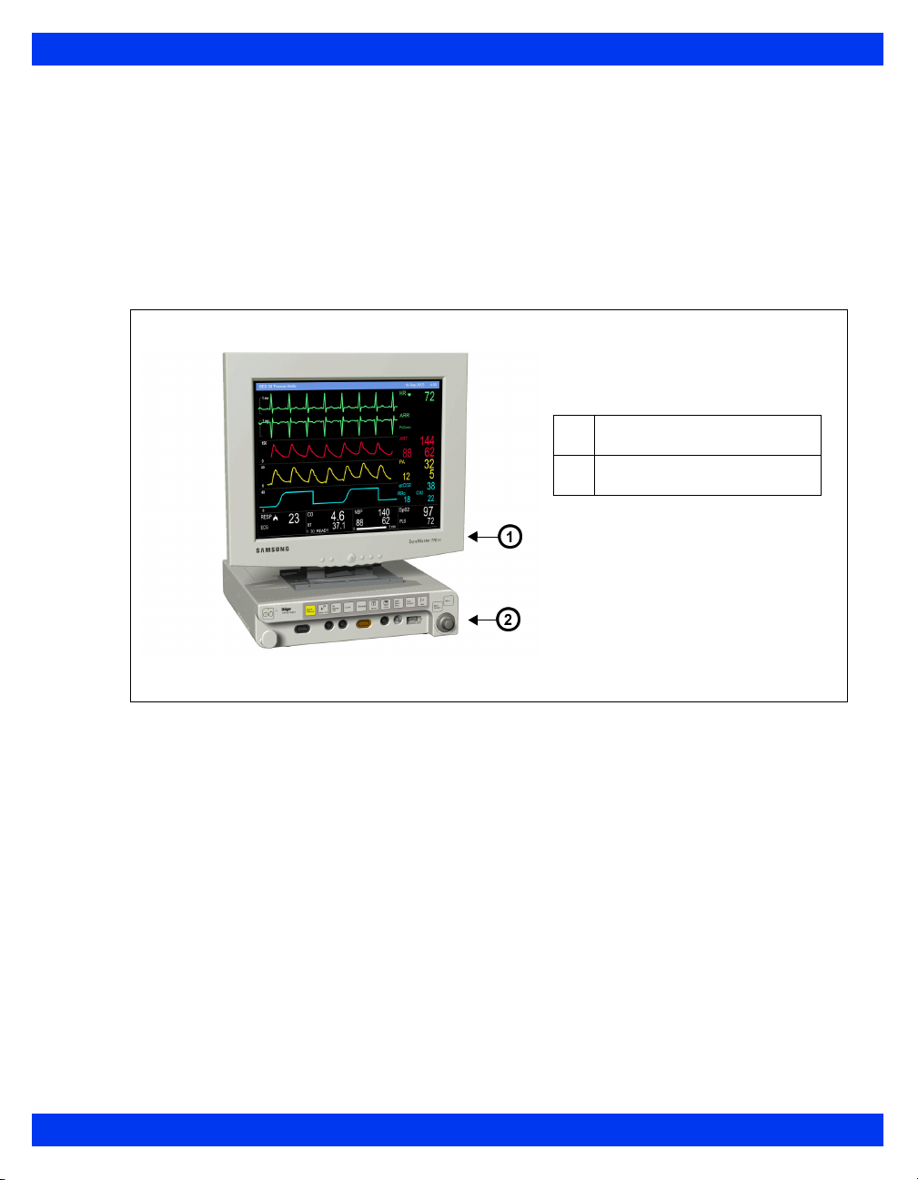
Overview (Kappa)
The basic Kappa monitoring system consists of two components: a processing CPU
base unit and a display unit. These Instructions for Use use the word “Kappa” monitor
to refer to the CPU base unit, unless otherwise specified. The Kappa is designed to
operate with a separate large screen display.
The monitor displays trended data in graphical and tabular trends.
Kappa Monitoring System
Display unit
1
Kappa base unit
2
OVERVIEW
VF8 DELTA/DELTA XL/KAPPA 1-3
Page 26

1 I
NTRODUCTION
System Components
NOTE:
For a complete list of accessories available with this product, see Appendix C.
The monitor configuration may vary. Refer to your hospital’s technical
personnel for more information.
The parts below include standard and optional components.
The Delta or Delta XL requires:
Monitor
Power supply
Country specific power cord and monitor
MultiMed or NeoMed cables
Optional: Infinity Docking Station (IDS) for mounting, power, and
networking capabilities
The Kappa requires:
Monitor front end
Country specific power cord
A display unit
MultiMed or NeoMed cables
Applicable Software Options (on a memory option card) include:
Options for Delta only:
Delta second PodPort option
Options for Kappa only:
Kappa 4 to 5 channel option
Kappa advanced communication option II
Delta and Kappa only:
Delta and Kappa 5 to 6 channel option
Delta and Delta XL only:
OR Mode option (loaded in the IDS)
1-4 DELTA/DELTA XL/KAPPA VF8
Page 27
Delta, Delta XL and Kappa:
Delta/Delta XL MIB II 1 to 4 option for IDS/ Kappa - advance
communication
6 to 8 channel option
3-Lead ST analysis option
Wireless networking option
ARIES option
Physio calculations option
ACE full arrhythmia option
ARIES/Physio Calcs/ACE arrhythmia option package
OR mode option (loaded in the monitor)
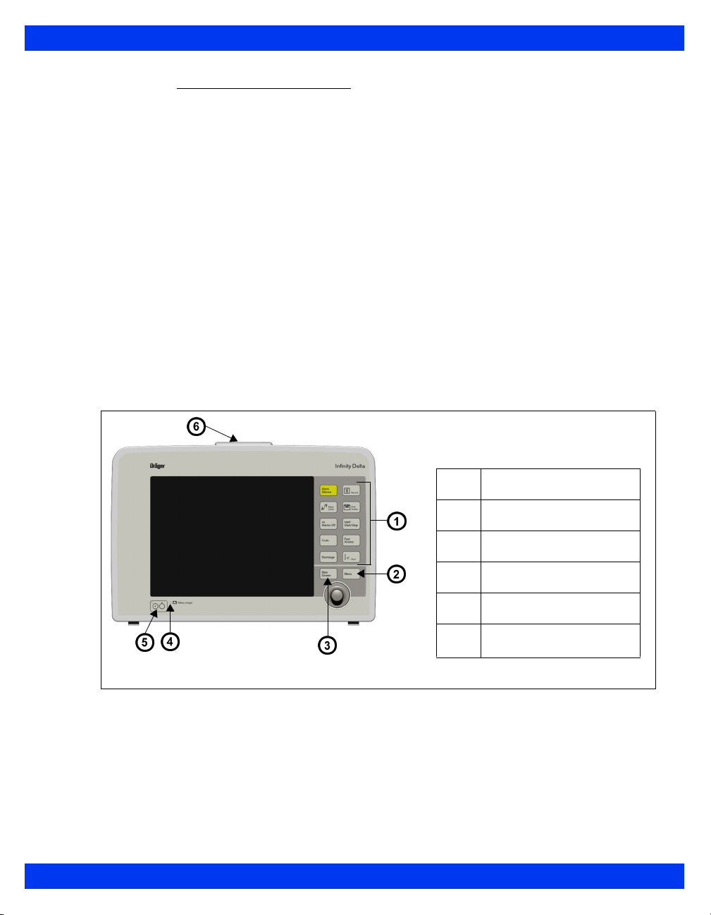
Base Unit
Monitor Front View – Delta
OVERVIEW
1
2
3
4
5
6
Fixed keys
Main menu fixed key
Main screen fixed key
Battery charge indicator
Power switch
Alarm bar (not available
on SC 7000)
VF8 DELTA/DELTA XL/KAPPA 1-5
Page 28
1 I
NTRODUCTION
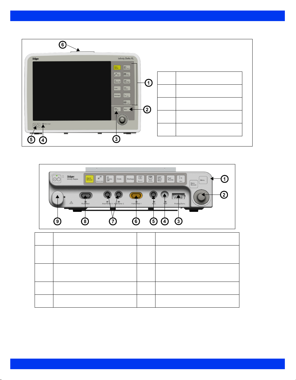
Monitor Front View – Delta XL
Monitor Front View – Kappa
1
Fixed keys
1
2
3
4
5
6
HemoMed connector
Fixed keys
Main menu fixed key
Main screen fixed key
Battery charge indicator
Power switch
2
3
4
5
Rotary knob
Analog (balloon pump)/sync
(QRS sync defib) connector
NBP hose connector
Auxiliary PodCom connector
7
8
9
Connectors for Aux/Hemo or
PodCom
MultiMed connector
Cable strain relief
1-6 DELTA/DELTA XL/KAPPA VF8
Page 29
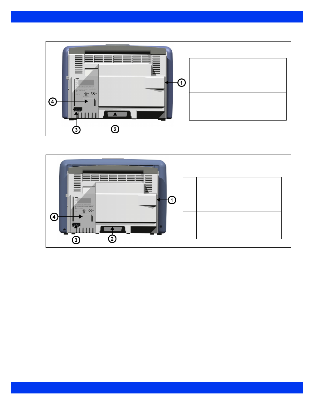
Monitor Rear View – Delta
Monitor Rear View – Delta XL
External (lead-acid) battery
1
compartment
Connector for docking station/
2
interface plate
Connector for AC adaptor
3
Slot for etCO2 module
4
External (lead-acid) battery
1
compartment
Connector for docking station/
2
interface plate
OVERVIEW
Connector for AC adapter
3
Slot for etCO2 module
4
VF8 DELTA/DELTA XL/KAPPA 1-7
Page 30
1 I
NTRODUCTION
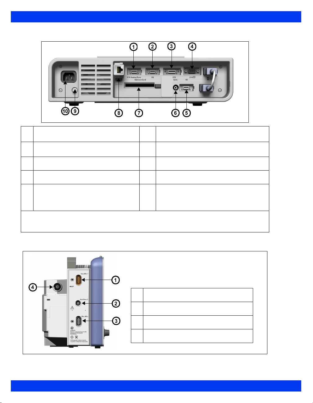
Monitor Rear View – Kappa
Analog out / Sync (balloon pump/
1
defibrillator) (X10)
Alarm output (nurse call)1, export
2
protocol (X5)
Recorder output (X13) 8 Infinity network connector (X14)
3
Video out (VGA) (X16) 9 Potential equalization
4
RS232 connector, Scio module, Smart
5
Pod, remote keypad, Vital Connect
Cable (VCC), Alarm output (nurse
call)2 – (X8)
1
NOTE: Alarm output (nurse call) requires the alarm output cable with partnumber 5194928.
2
NOTE: Alarm output (nurse call) requires the alarm output cable with partnumber 4314626.
QRS Sync (for example, for defibrillator
6
connection)
7 PCMCIA slot (“Memory card”)
10 AC input
Monitor Left Side – Delta
HemoMed connector
1
Connectors for Aux/Hemo or PodCom
2
MultiMed connector
3
NBP connector
4
1-8 DELTA/DELTA XL/KAPPA VF8
Page 31

Monitor Left Side – Delta XL
1
2
3
4
Monitor Left Side – Kappa
HemoMed connector
Connectors for Aux/Hemo or PodCom
MultiMed connector
NBP connector
Advanced Communications
1
Options
CANBUS connector for old Scio
2
module (PN 68 71 255)
MIB connectors
3
OVERVIEW
Scio/Independent Surgical Display
4
(ISD) connector
VF8 DELTA/DELTA XL/KAPPA 1-9
Page 32

1 I
NTRODUCTION
Monitor Right Side – Delta/Delta XL
Monitor Right Side – Kappa is blank
CAUTION:
PCMCIA slot: memory card
1
Infinity network connector
2
QRS sync
3
RS232 connector, Scio module, Smart Pod,
4
remote keypad, Vital Connect Cable (VCC),
Alarm output (nurse call)1 – (X8)
Analog out (X10)
5
1
NOTE: Alarm output (nurse call) requires the
alarm output cable with partnumber 4314626.
The Kappa video display is not battery-backed. When power is lost, nothing
appears on screen unless the video display is connected to an Uninterruptable
Power Supply (UPS). Dräger recommends the use of a UPS with the Kappa
video display. The UPS must meet the electrical safety requirements of IEC
60601-1 or be connected to an isolation transformer that meets those
requirements (see the “Electrical Safety” section).
Connecting the Kappa monitor, Video display unit, and the optional UPS
requires multiple line cords. To reduce the chance of electromagnetic
interference from magnetic fields, the power cords should be run as close
together as reasonably possible to reduce loop area.
The video output connector on the back of the Kappa is not galvanically
isolated.
If you use a video monitor other than one specified by Dräger, it must comply
with IEC 60601-1 and be suitable for use in the presence of flammable
anesthetic mixtures (see “Safety Considerations” on page 6). Based on the
intended use of the system, the video monitor must also have suitable
classifications for water ingress protection as well as radiated and conducted
emissions. Upon installation, the installer must make sure that all of these
requirements are met.
1-10 DELTA/DELTA XL/KAPPA VF8
Page 33

Kappa Video Display
The Kappa complies with the requirements of IEC 60601-1 when used with Dräger
approved medical grade displays, available in multiple screen sizes (see page B-18.)
CAUTION: The remote display output on the IDS is not galvanically isolated. If you use
a video monitor other than one specified by Dräger, it must comply with IEC 60601-1
and be suitable for use in the presence of flammable anesthetic mixtures and/or
flammable liquids (see “Safety Considerations” on page 6”). Based on the intended use
of the system, the video monitor must also have suitable classifications for water ingress
protection as well as radiated and conducted emissions. Upon installation, the installer
must make sure that all of these requirements are met.
OVERVIEW
VF8 DELTA/DELTA XL/KAPPA 1-11
Page 34

1 I
NTRODUCTION
Device Markings
The following table describes symbols that appear on the monitor and its accessories
that were not described on pages 1-5 through 1-10:
Monitor on/off Remote keypad in
Battery-operated
equipment
Attention! Consult the
accompanying document
Defibrillator-proof equipment,
Type CF
Direct current Analog out
Danger: Risk of explosion if
used in presence of flammable
anesthetics
Isolated patient connection,
Type CF
Complies with the European
Medical Device Directive 93/
42/EEC
Type BF, defibrillator
protected
Gas in Contains no latex material
Gas out Manufacturer’s lot number
RS 232
Analog out
Analog out
Push battery all the way into
compartment.
Close battery compartment
door.
This end up
Artery symbol and arrow
should be placed over
brachial or femoral artery.
Observe WEEE (Waste
Electrical and Electronic
Equipment) disposal
requirements (see page 2).
Manufacturing date REF Manufacturer’s reorder code
Alarm out Does not provide isolation
Monitor is receiving AC power Potential equalization
Certain cuff codes are
ethylene oxide sterile.
between connected devices
terminal
1-12 DELTA/DELTA XL/KAPPA VF8
Page 35

China RoHS marking Video display output
Contains lead - Recycle
properly
Auxiliary Display and Other Components
The following devices enable remote viewing of patient data.
Remote Display – Allows you to view but not control monitor functions away
from the bedside. Dräger strongly recommends that you use only approved
video monitors, otherwise the function of the monitor may be compromised.
For a complete list of approved video monitors, contact your Dräger local
representative to obtain a catalog. Any use of non-approved monitors may
compromise the correct functioning of the device. If you use an alternative
video monitor, be advised of the following information.
CAUTION: The remote display output on the IDS is not galvanically isolated. If you use
a video monitor other than one specified by Dräger, it must comply with IEC 60601-1
and be suitable for use in the presence of flammable anesthetic mixtures and/or
flammable liquids (see “Site of Operation” on page 7). Based on the intended use of the
system, the video monitor must also have suitable classifications for water ingress
protection as well as radiated and conducted emissions. After installation, the installer
must make sure that all of these requirements are met.
OVERVIEW
Surgical display controller – Allows you to display information acquired by
the Surgical Display Interface on a remote video display. It provides a special
interface adapted to the needs of surgeons and other operating-room
personnel (see page 28-20 for more information).
NOTE: The Kappa monitor can only connect to the Surgical Display Interface (SDI)
if the monitor is equipped with the advanced communication option.
Remote keypad – The optional remote keypad allows you to operate the
monitor from a distance. A rotary knob and fixed keys duplicate those of the
monitor and pods, while a numeric keypad allows you to enter data. See page
1-22 for more information.
Export protocol – Allows you to share data with other Dräger and third-party
devices (for example, clinical information and anesthesia record systems and
data loggers; see Dräger publication Infinity RS-232 Export Protocol
Reference Booklet).
VF8 DELTA/DELTA XL/KAPPA 1-13
Page 36

1 I
NTRODUCTION
MIB protocol converters – The monitor can display numeric, waveform, and
trended data generated by external monitoring devices. Dräger provides
protocol converters that translate the output from external devices into the
Medical Information Bus (MIB) protocol, using the appropriate 1073
standards (IEEE 1073.3.2 or 1073.3.1 and 1073.4.1). For more information,
see chapter 28.
R50 series recorders – Produce alarm, timed, continuous, and trend
recordings. See chapter 7, for more information about R50 and R50-N
recorders.
PCMCIA card – Allows you to transfer data, upgrade software, store setups,
download setups, and store diagnostic logs.
QRS Sync. output –Allows you to synchronize defibrillators to the patient’s
heart beat during cardioversion.
Balloon pump interface – Permits interaction with a balloon pump by
providing two analog output signals (ECG and ART).
Power Sources (Delta/Delta XL)
The Delta/Delta XL monitor can be powered by the Infinity Docking Station (IDS), a
hospital grade outlet with AC adapter, or battery. In case of a line outage or
disconnected cable, the monitor automatically switches to battery power to provide
continued patient monitoring without any loss of data.
CAUTION: See the section “Safety Considerations” on page 6 in these Instructions for
Use before connecting the monitor to a power source.
1-14 DELTA/DELTA XL/KAPPA VF8
Page 37

POWER SOURCES (DELTA/DELTA XL)
Infinity Docking Station (IDS)
The Infinity Docking Station (IDS) helps facilitate patient transport, allowing you to
remove the monitor from the bedside and dock it at another station while maintaining
patient and monitor connections. This feature, called Pick and Go, is explained in
further detail on page 3-5. With its companion DC power supply, the IDS provides
power and data connection, stores setup defaults, and connects your monitor to a
network.
Infinity Docking Station
(Rear View)
1
alarm output cable with partnumber 5194928
1 MultiGas module
2 Power supply
3 Export protocol/alarm output
(nurse call)
(X3)
4 Independent Surgical Display
(ISD) (X4)
5 Network
6 R50 series recorder (X13)
7 Video out / Remote display
(X5)
8 Potential equalization
9 MIB connectors
NOTE: Alarm output (nurse call) requires the
1
, Scio module,
Battery Power
The Delta/Delta XL monitor operates on an external, sealed lead-acid battery and an
internal lithium ion battery. The external battery, which can easily be replaced when
depleted, can power the monitor for approximately 50 minutes. If it runs low or you
remove it from a monitor that has been using battery power, the monitor automatically
switches to an internal battery, which can power the monitor for approximately 180
minutes (see page B-8).
NOTE: The SC7000/9000XL monitor's internal lead-acid battery can power the
monitor for approximately 75 minutes.
VF8 DELTA/DELTA XL/KAPPA 1-15
Page 38

1 I
NTRODUCTION
WARNING: Worn out or defective batteries can significantly
reduce these times.
When both batteries run low, the monitor sounds an alarm, and a status message
appears in the network message area. If both batteries are depleted, the monitor turns
off automatically.
The external battery fits into a compartment on the
monitor’s left side. When depleted or removed, replace
Insert
battery here
it immediately or connect the monitor to a power
supply. The battery is being charged (as indicated by the
battery charger LED on the front panel) whenever the
monitor is connected to AC power.
The internal battery is charged first, then the external
battery. The table below illustrates the function of the
battery charge bar graph at the top of the screen:
CAUTION: The battery charger display is only accurate if the batteries are in normal
working condition.
NOTE:
When AC power is disconnected, the battery charge display takes up to 15
seconds to reflect the internal battery's actual capacity and up to 60 seconds to
reflect the external battery's actual capacity.
The battery indicator is not displayed if the monitor is not connected to the
Infinity network and the setting
the setting
Network Control is set to ON. To display the battery indicator under
these circumstances, the setting
Network Mode is set to Direct Net Mode and
Network Control must be set to OFF.
Battery
Battery Charge Display
Display Charge Left Action
The battery is fully charged Not applicable
The battery is half full Connect the monitor to an IDS or AC
The external battery is very low
(< 25 %)
The external battery is deplete.
adapter.
Replace with a fully charged external
battery.
1
Replace with a fully charged external
battery.
1-16 DELTA/DELTA XL/KAPPA VF8
Page 39

POWER SOURCES (DELTA/DELTA XL)
Battery Charge Display
Display Charge Left Action
1
The monitor sounds single attention tone.
Internal battery is very low
(<25%).
Immediately connect monitor to AC
adapter, or Infinity Docking Station.
Replace external battery.
Internal battery is depleted; <5
minutes of power remaining.
2
The monitor sounds attention tone every 5 seconds.
2
CAUTION:
It is strongly recommended that you use batteries that are provided by Dräger.
The use of non-approved batteries may damage the device.
Do not transport the patient using this monitor if the internal battery charge is
at 25% or less, unless you are using a fully charged external battery.
High temperatures may adversely affect batteries. For optimal performance,
charge and use external batteries at temperatures below 35 °C (95 °F).
Follow local regulations for disposal of batteries. To prevent fire or explosion,
never dispose of batteries in fire.
NOTE:
To maximize the available charge for transport, leave the monitor connected
until you are ready to move the patient. Reconnect the monitor immediately
after transport.
Dräger recommends replacing any lead-acid or lithium ion battery after 24
months of continued use. Battery life may vary depending upon usage.
To prevent premature depletion, recharge the batteries immediately after
discharging them. This is particularly important for lead-acid batteries which
degrade rapidly if left in an uncharged state for several days.
In storage, lead-acid batteries discharge slowly over time and may become
depleted after several months. Batteries stored for use with the monitor should
be recharged every six months.
Immediately connect monitor to AC
adapter, or Infinity Docking Station.
Replace external battery.
VF8 DELTA/DELTA XL/KAPPA 1-17
Page 40

1 I
NTRODUCTION
Charging the Batteries
Before using the Delta/Delta XL monitor for the first time, charge the internal battery
for a maximum of 6.5 hours and the external battery for 3.5 hours.
NOTE: For the SC 7000/9000XL internal lead-acid battery, charge for a maximum of
4.5 hours the first time.
When the monitor receives DC power, batteries recharge automatically. The optional
SLA Battery Charger can charge four fully depleted external batteries simultaneously
in approximately 3.5 hours. To start a fast-charge, insert the batteries into the slots of
the battery charger with the metal contacts facing down.
CAUTION: The battery charger display is only accurate if the batteries are in normal
working condition.
Power Sources (Kappa)
WARNING: Read the sections “Safety Considerations” on
page i-6” and “Kappa Video Display” on page 1-11 of these
Instructions for Use before connecting the monitor to a power
source.
The Kappa monitor uses AC power (100-240 VAC). In case of a line outage or
disconnected cable, the monitor automatically switches to battery power to provide
continued patient monitoring without any loss of data. The base unit continues to
operate and alarm on battery power for approximately 20 minutes.
An internal battery can power the Kappa
for up to approximately 20 minutes depending on the monitoring setup. It is intended
for short-term use only, for example, as a backup during power interruptions.
WARNING: Worn out or defective batteries can significantly
reduce this time.
monitor (but not the Kappa video display)
1-18 DELTA/DELTA XL/KAPPA VF8
Page 41

POWER SOURCES (KAPPA)
When the monitor is operating solely on battery power, a message along the top of the
screen tells you if the battery charge is low, and a bar graph indicates how much
power is left (see the table below.) The battery is automatically recharged whenever
you plug the monitor into an AC outlet.
CAUTION: The battery charger display is only accurate if the batteries are in normal
working condition.
NOTE: When the monitor is disconnected from AC power, the battery charge display
takes up to 60 seconds to reflect the battery's actual capacity.
Battery Charge Display
Display Charge Left Action
The battery is fully charged Not applicable
The battery is half full Connect to power
The battery is very low; < 25% of power
remaining
The battery is depleted; < 3 minutes of
power remaining. The monitor sounds
an attention tone every 5 seconds.
Immediately connect the monitor to
power.
VF8 DELTA/DELTA XL/KAPPA 1-19
Page 42

1 I
NTRODUCTION
Getting Started
To turn the monitor on
Press the power key (
), located on the bottom left of the Delta or Delta XL
O
monitor's front panel and on the top left of the Kappa monitor’s front panel.
The monitor turns on the power indicator light, lights the alarm bar, emits a
power-on tone, lights up the screen, performs a self-test, and displays the
main screen.
To turn the monitor off
Press and hold the power key (O) for two seconds. The power indicator light
turns dark, and the monitor emits a power-down tone.
Accessing the Main Screen
After you power up the monitor, the main screen appears. To return to the main screen
from a menu or other display:
Press the Main Screen fixed key, located just above the rotary knob on the
front panel of the monitor. The main screen appears, as shown in the
following illustration.
Network message
1
Parameter boxes
2
Waveforms
3
Local message
4
The standard Delta monitor provides five waveforms with adjacent parameter boxes.
Kappa provides four waveforms with adjacent parameter boxes. Delta XL provides
six waveforms with adjacent parameter boxes. Channels can be added to display up to
eight waveforms. The bottom channel can be used to display additional parameter
boxes (see “Bottom Channel” on page 2-6).
1-20 DELTA/DELTA XL/KAPPA VF8
Page 43

GETTING S TARTED
Parameter boxes show values, alarm limits, and special icons for selected parameters.
Parameters and their associated waveforms are color-coded for easy recognition.
NOTE:
You can access parameter setup menus by scrolling through the parameter
boxes using the rotary knob and selecting the parameter you wish to configure.
See “Quick Reference – Main Menu Setup” on page 2-3 to access parameter
setup menus.
You can change the default color coding for each parameter by accessing the
Parameter Colors menu (see page 2-23). For a list of default parameter colors,
see page 2-23.
Messages appear along the top of the screen. Local messages appear in the local
message area (left) while network messages appear in the network message area
(right). When there no local messages are displayed, the monitor displays the patient’s
name and bed label. When no network message is displayed, the date and time appear
instead.
Using the Rotary Knob
The rotary knob allows you to browse menus, choose settings, and execute
menu functions. Scroll through menu items by turning the rotary knob.
Press the rotary knob (or click) to confirm.
To use the rotary knob
1. Select the required function by dialing the rotary knob.
2. Press the rotary knob and click to confirm your selection. A list of choices
appears or the field switches to its alternate value, for example,
ON to OFF.
You can also use the rotary knob to enter letters or
numbers.
1. Click on a field (for example,
Physician).
The monitor displays a data-entry screen
similar to the following:
2. Use the rotary knob to select each
character or number, then click to
confirm. Use the control buttons at the
bottom of the screen for editing.
3. Click on
Accept to confirm the entire entry or on Cancel to exit the data entry
screen.
VF8 DELTA/DELTA XL/KAPPA 1-21
Page 44

1 I
NTRODUCTION
Remote Keypad
NOTE: The remote keypad's C.O. key is not available with the PiCCO pod.
The remote keypad has all of the fixed keys that are on the monitor and additional
keys that perform the following:
To connect the remote keypad to the monitor
(Delta/Delta XL) – Plug one end of the keypad cable into the keypad and the
other into the connector marked RS232 on the right side of the monitor.
(Kappa) – Plug one end of the keypad cable into the keypad and the other end
into the keypad input connector on the monitor’s rear panel.
Trends — Displays trend graphs
Freeze — Freezes waveform display
Calcs. — Activates Calculations menu
All ECG — Displays Show All Leads screen
Remote View — Displays Remote View menu
Recall Setup — Displays Restore Setups menu
View+ — Toggles from monitor to secondary (display) screen
Menu Access
There are two ways of accessing the menus. The Fast Access menu allows you to open
commonly used menus quickly. The main menu lists the primary menus (Patient
Setup, Monitor Setup, etc.), which allow you to access additional menus.
1-22 DELTA/DELTA XL/KAPPA VF8
Page 45

MENU A CCESS
Fast Access Menu
The Fast Access menu accesses the following submenus and screens directly:
Fast Access Item See page Fast Access Item See page
Remote View 3-13 Calculations 16-1
OxyCRG (Neonatal only) 12-9 Show All Leads 8-18
Alarm History 5-14 Lab Data 16-8
Trend Graphs 6-3 Open Lung Tool (via MIB
only)
Trend Table 6-6 OR 2-12
Event Recall 1-27 Split Screen 2-7
Drug Dosage 16-12
28-12
To open the Fast Access menu
Press the Fast Access fixed key located on the front of the monitor.
You can access many of these menus by selecting
Review on the main screen. See
page 2-5 for more information.
Main Menu
The Main menu allows you to execute certain functions and access others. Icons are
used to identify menu items:
Page icon (for example, Restore Setups) – Accesses a submenu
Arrow icon (for example, Review) – Displays another column
No icon (for example, Standby) – Executes a function
To display the Main menu
1. Press the Menu fixed key. The primary list of Main menu options appears.
2. Click on a page icon next to a heading ( ) to open a main menu submenu or
on an arrow icon ( ) to display another column of main menu options (see
page 2-2 for detailed information on configuring the main menu).
VF8 DELTA/DELTA XL/KAPPA 1-23
Page 46

1 I
NTRODUCTION
Fixed Keys
Fixed keys on the monitor front panel allow you to perform commonly executed
functions.
Fixed Key Description Fixed Key Description
Alarm
Silence
Alarm Limits Opens a table from which you
All Alarms
Off
Code Activates a set of monitor
Discharge Accesses the Discharge menu.
Main Screen Activates the main screen. Freeze
Silences the active alarm tone
for one minute
can set upper and lower alarm
limits
Suspends all alarms for a preselected time or cancels the
suspension
functions for urgent care
NOTE: Press the Discharge
key a second time to discharge
the patient.
Record Starts/stops a timed
Print
Screen
NBP
Start
Stop
Fast
Access
Mark Stores data with the current
(Delta XL
only)
Menu Activates the main menu.
Control Buttons
recording.
Prints the currently displayed
screen to a network laser
printer.
Starts or stops a non-invasive
blood pressure (NBP)
measurement.
Displays the Fast Access
menu.
time stamp.
Freezes the waveforms.
Control buttons are located along the bottom of the various screens, trend tables,
graphs, loop displays, etc. They permit additional screen-specific settings.
1-24 DELTA/DELTA XL/KAPPA VF8
Page 47

DATA ARCHIVE APPLICATIONS
Data Archive Applications
The monitor stores events, alarms and trends automatically or at the user’s request,
depending on the type of information. Some events are automatically recorded and
stored. Others can be stored manually by pressing the
automatically stores alarm conditions and arrhythmia events that you have configured
for storage in the Alarm Limits table (see page 5-6) and in the Arrhythmia setup table
(see page 9-6).
NOTE: You cannot disable event storage for asystole and ventricular fibrillation
events. The monitor stores these events automatically.
You can access archived information in one or more of the following databases:
Trends
Calculations
Alarm history
Event recall
Each database indicates the time of the data capture and parameter values and/or
waveforms active at the time of capture. Trends, Calculations, and Alarm History are
discussed in the following chapters (Event Recall and Storage is explained later in this
section.):
Mark fixed key. The monitor
Trends, see chapter 6. Stored events are marked with the time and date of
capture as follows:
— Trend table; an icon ( ) over the time line marks manually stored events
only. (Automatically stored alarms and arrhythmia calls are not marked in the
trend table.)
— Trend Graphs; a small yellow vertical line at the top of the screen marks
manually and automatically stored events.
Calculations; see chapter 16.
Alarm history; see chapter 5.
VF8 DELTA/DELTA XL/KAPPA 1-25
Page 48

1 I
NTRODUCTION
Storing Events
Automatic Storage
The monitor stores events automatically, if you have first correctly configured the
Alarm Limits and Arrhythmia Setup tables.
You can enable individual parameter alarms in the
Limits and/or the ARR Setup screens. Configure event storage in the
by selecting
Store or Str./Rec.
Alarms column of the Alarm
Archive column
Storing Data Manually (Mark Key)
The Mark fixed key on the front of the monitor allows you to capture an event
manually. All data displayed on the Main Screen at the time of capture is archived for
later identification and comparison.
The number of events you can store depends on the
Main Screen menu (see page 2-5). If the
stores four sets of waveforms; if set to
are captured, stored, and displayed in pairs.
Max. Channels setting is 8, the monitor
6, the monitor stores three sets, etc. Waveforms
Max. Channels setting on the
To store data manually
Press the Mark fixed key on the front of the monitor to capture all
waveforms and parameter values currently displayed on the main screen.
1-26 DELTA/DELTA XL/KAPPA VF8
Page 49

DATA ARCHIVE APPLICATIONS
Event Recall
The monitor stores monitoring data (waveforms and parameter values), alarm
conditions, and arrhythmia events on the Event Recall screen. You can view up to 50
stored events, each containing 20 seconds of data, with associated date and time
stamps. Events are stored on a first-in, first-out basis. When event storage is full, the
monitor deletes the oldest events to make room for new ones. All stored events are
deleted whenever you discharge a patient, reset the monitor, or temporarily lose
power.
To access the Event Recall screen
1. Press the Fast Access fixed key.
2. Click on
Time of capture
1
Parameter values at time of capture
2
Print report
3
Requests recording
4
Saves/Deletes events
5
1
View: All - displays all stored events; Manual - displays manually stored events;
Alarm - displays alarm events only; BRDY - displays bradycardia events only;
Desat (Neonatal only) - displays desaturation events only
2
Parameter display: Prev - displays previous set of (2) parameters; Next - displays
next set of (2) parameters
Event Recall to display the Event Recall screen.
View1:
6
Parameter display2:
7
Parameter labels
8
Waveform delay and speed
9
VF8 DELTA/DELTA XL/KAPPA 1-27
Page 50

1 I
NTRODUCTION
Navigating the Event Recall Screen
To scroll forward and back through 20 seconds of waveform data, click on arrows at
either side of scroll bar at the bottom of the screen.
To scroll through the list of parameter values at the time of data capture, click on the
arrow keys above the list of parameters at the right of the screen:
To scroll through the waveforms displayed at the time of data capture, click on the
Prev (Previous) and Next control buttons under waveform display.
Help Functions
You can display a short description of currently highlighted functions at the bottom of
all active menus by enabling context-sensitive help.
1. Press the
2. Click on
3. Open the
4. Select
Additional information about the monitor is available in the Main Help menu.
1. Press the
2. Click on
3. Click on the appropriate selection in the table below.
Menu Item Description
Locked Options Displays active software options currently installed on the monitor.
Fixed Keys Describes functions of fixed keys.
Menu fixed key to open the Main menu.
Monitor Setup. Another column of options appears.
Display Options menu by clicking on that heading.
Help Line Display and click to choose ON.
Menu fixed key.
Help. The Main Help Menu appears.
1-28 DELTA/DELTA XL/KAPPA VF8
Page 51

2 Monitor Setup
Overview.........................................................................................................................2-2
Configuring the Monitor................................................................................................2-2
Main Menu Setup.....................................................................................................2-2
Quick Reference – Main Menu Setup ....................................................................2-3
Setups Management......................................................................................................2-9
Specialty Menus...........................................................................................................2-12
OR Mode ................................................................................................................2-12
Unit Manager .........................................................................................................2-14
Biomed ...................................................................................................................2-20
Parameter Colors ..................................................................................................2-22
Software Upgrades ......................................................................................................2-24
Page 52

2 M
ONITOR SETUP
Overview
This chapter describes how to configure the monitor and offers tips on software
upgrades. If the monitor is connected to a network, you can save defined setups and
restore them for display.
Configuring the Monitor
Main Menu Setup
The Main menu allows you to access submenus, display screens, and execute certain
monitor setup functions.
1. Press the
2. Click on a page icon ( ) to open a submenu associated with the Main menu,
or
Click on arrow icon ( ) to display another column of submenu options.
3. Click on the desired setting to execute functions or access further submenus.
4. Click on
left corner of the screen to return to prior menu or screen.
Menu fixed key to display the Main menu.
Exit at the bottom of a submenu list or on the white arrow in upper
2-2 DELTA/DELTA XL/KAPPA VF8
Page 53

CONFIGURING THE MONITOR
Quick Reference – Main Menu Setup
The Main Menu
Menu Item Description Available Settings
Cursor Tool Provides access to the Cursor Tool
Setup Opens Cursor Tool setup menu. • Waveform (up to 3)
Horizonta
l
Cursor
(One for each
waveform on
display)
submenu (see below), which allows you
to select three waveforms displayed with
horizontal cursors and a vertical cursor.
The Cursor Tool Submenu
Displays a horizontal cursor. User can
scroll up and down each waveform.
NOTES:
• Cursor value is displayed
• Cursor and value remain displayed until
the window closes.
• Buttons remain ghosted until you press
the Stop key.
1
.
•Setup
• Horizontal Cursor
•Stop
•Hemo/Calcs
• Vertical Cursor
NOTE: In 4-channel mode, a maximum
of 2 waveforms are available.
• Sweep Speed
• 6.25 mm/sec
• 12.5 mm/sec
• 25 mm/sec (Default)
• 50 mm/sec
Not applicable
To exit the cursor tool:
• Press/click the rotary knob to exit the
cursor control.
or
• Press the Main Screen fixed key.
Stop Stops scrolling of all waveforms in the
Hemo/Calcs Opens the hemo/calcs screen.
1
The cursor value is displayed only if a scale is associated with the waveform. Waveform scales
are the same as parameter main display.
cursor tool display and makes the
Horizontal and Vertical Cursor buttons
selectable.
NOTES:
• The button is ghosted unless a license
is present.
• The advanced calcs menu is available if
the option is installed.
Not applicable
Not applicable
VF8 DELTA/DELTA XL/KAPPA 2-3
Page 54

2 M
ONITOR SETUP
The Main Menu
Menu Item Description Available Settings
Vertical
Cursor
Review Provides access to submenus of the Main
Patient
Category
Displays a vertical cursor. You can scroll
forward and backward across all
waveforms.
NOTES:
• The cursor has no value.
• The cursor remains displayed until the
window closes.
• The buttons remain ghosted until you
press the Stop key.
To exit the Cursor tool:
• Press/click the rotary knob to exit the
cursor control.
or
• Press the Menu, Main Screen, Alarm
Limits, Fast Access, or Discharge
fixed key.
menu display (see page 2-2).
The Patient Setup submenu
Determines the availability of monitoring
features such as apnea detection
(neonates only) and ventilation.
Not applicable
• Click on Review to open the following
submenus and displays: Alarm
History, Trend Graphs, Trend Table,
Event Recall, Calc. Results, OxyCRG
(neonatal mode only), Show All
Leads, Lab Data, and Open Lung
To ol .
• Click on Exit to return to the first
column of the Main menu.
•Adult
• Pediatric
•Neonatal
NOTES:
• Clicking on a setting displays a popup
message that warns you that things will
change if you confirm the action. Click
on the category of your choice again to
confirm the action.
• If you change a patient’s category, the
weight selection is cleared and must be
selected again.
Pressure
Labels
Assigns IBP pressure channel labels (see
chapter 14, for detailed information).
ART, PA, CVP, LA, LV, RV, RA, ICP,
ICP2, ICP3, ICP4, GP1, GP2
2-4 DELTA/DELTA XL/KAPPA VF8
Page 55

CONFIGURING THE MONITOR
The Main Menu
Menu Item Description Available Settings
Parameters Accesses the parameters’ setup menus. • Click on one of the listed parameters
Alarm Limits Opens the alarm limits table See page 5-6
The Monitor Setup submenu
Main Screen
This submenu allows you to layout the main screen. To access the second page of this menu, click
on the down arrow at the bottom of the screen. Click on the up arrow to return to this page.
Parameter
Priority
Allows you to modify the order of
parameters displayed on the Main Screen
without regard to whether or not that
parameter is connected.
NOTES:
• Parameters must be assigned a priority;
whether they appear on the main screen
depends on their priority and on the
number of channels configured to
display waveforms (see Max. Channels
on page 2-6).
• In Automatic display mode, connected
parameters are displayed according to
their priority in the Parameter Priority
list. If all available channels are filled, a
higher priority parameter will NOT
“bump” lower priority parameter boxes
off the Main Screen when the
associated device is connected. In order
to display the parameter, the user must
double-click on the parameter in the
Parameter Priority list.
• In OR Mode, if all available channels are
filled, a higher priority parameter will
“bump” lower priority parameter boxes
off the Main Screen when the
associated device is connected.
to access its setup menu: (for
example, ECG, ARR, ST, ART, PA
CVP, RA, SPO2, NBP, RESP,
etCO2, C.O.
NOTE: The parameters that appear in
this list depend upon the monitor's
configuration and which devices are
connected.
• Click on Exit to return to the first
column of the Main menu.
To change a parameter's display order:
1) Scroll to Display Mode.
2) Select Manual.
3) Click on Parameter Priority to
highlight the first listed parameter.
NOTE: Parameters are numbered
according to their priority. The display
is color coded: A green parameter
label indicates that the associated
parameter device (for example, an
NBP hose/cuff) is connected to the
monitor. A white label indicates that the
device is not connected.
4) Scroll the list to the parameter you
wish to move and click.
5) Move the parameter to its new place
using the rotary knob.
6) Click to confirm the parameter’s new
position on the list.
7) Click again to return to Parameter
Priority.
8) Scroll to the arrow at the upper left
corner of the menu to exit, or
continue to set up other Main
Screen submenu functions.
VF8 DELTA/DELTA XL/KAPPA 2-5
Page 56

2 M
ONITOR SETUP
The Main Menu
Menu Item Description Available Settings
Max.
Channels
Bottom
Channel
ECG
Channels
ARR
Monitoring
ST
Monitoring
RESP
Monitoring
Display
Mode
Agent
Display
N2O Display Displays N
Determines the number of waveform
channels and parameters displayed.
Configures the bottom waveform channel
to display a waveform or 3 parameter
boxes.
Determines the number and format of
ECG waveforms displayed.
Selects the Arrhythmia mode
(For detailed information, see page 9-5.)
Enables and disables ST monitoring (for
detailed information, refer to chapter 10).
Enables and disables respiration
monitoring (for detailed information, refer
to chapter 12).
Reduces Main screen clutter by
displaying only parameters associated
with a connected device (see Parameter
Priority on page 2-5).
Displays an anesthetic agent parameter
box.
O/O2 parameter box.
2
NOTE: This selection is ghosted unless
MultiGas or MultiGas+ module is
connected.
• Click on 4, 5, 6, 7, or 8
NOTE: The number of waveforms
depends on the software option you
have installed (see page 1-20 for a list
of options).
Waveform, Parameters
Click on the following settings:
• ECG1 – Displays the primary ECG
waveform
• ECG1 & 2 – Displays 2 waveforms
• ECG1 & 2 & 3 – Displays 3
waveforms
• Cascade – Cascades ECG1 data
into second channel
•Select OFF to disable arrhythmia
monitoring.
•Select FULL to enable full arrhythmia
monitoring.
•Select BASIC to enable basic
arrhythmia monitoring.
•Select ON to enable ST monitoring.
•Select OFF to disable ST monitoring.
•Select ON to enable respiration
monitoring.
•Select OFF to disable respiration
monitoring.
•Select Manual to display all
parameters and assign them a
priority on the Parameter Priority
screen.
•Select Automatic to display active
parameters only.
•Select
•Select OFF to cancel display.
•Select ON to display N2O/O2.
•Select OFF to cancel display.
ON to display agent.
2-6 DELTA/DELTA XL/KAPPA VF8
Page 57

CONFIGURING THE MONITOR
The Main Menu
Menu Item Description Available Settings
MultiGas
Parameter
Displays a combined O2/Agent/N2O
parameter box.
To display the MultiGas parameter
box:
NOTE: You can also display or cancel the
MultiGas Parameter box from the O
setup menu (see chapter 23, for more
information).
Split Screen Reserves a portion of the main screen for
EEG
Channels
Display Options
This submenu allows you to access and modify waveforms and other display features by
configuring the following functions.
Monitoring
Sweep
Speed
Respiratory
Sweep
Speed
Pressure
Overlap
Pressure
Common
Scale
Monitor
Brightness
SC 9015
Brightness
Help Line
Display
Parameter
Units Display
display of trend graphs and ventilation
loops.
Sets number of EEG waveforms
displayed.
Determines the waveform speed. The
higher the sweep speed the quicker the
waveforms are move across the screen.
Allows you to set the sweep speed for the
respiration waveform independently of
other parameters.
Displays up to 4 overlapping IBP
waveforms in a single oversized channel.
Overlapped waveforms share a common
zero point, but each waveform retains the
original scale configuration (see page 14-
14).
Displays pressure waveforms with a
common scale, making it easier to
compare them.
Sets the brightness of the monitor screen. Click on Auto (ambient light), 20, 40,
Sets the brightness of the SC 9015.
Shows a contextual help line at bottom of
the menu.
Displays a unit of measure in the
parameter boxes.
• Click on MultiGas Parameter.
• Click again to toggle ON or OFF.
2
Click on one of the following:
•OFF
• 60 Min Trends
• 10 Min Trends
• Ventilation
• Click on 1, 2, 3, or 4.
Click on 6.25, 12.5, 25, or 50 mm/s
Click on 6.25, 12.5, 25, or 50 mm/s
•Select ON to display IBP waveforms
in overlapping format.
•Select OFF to cancel display of
waveforms in overlapping format.
Click on 5, 10, 15, 20, 25, 30, 40, 50,
75, 100, 150, 200, 250, 300 mmHg, or
OFF.
60, 80, or 100%.
•Select ON to display a help line.
•Select OFF to cancel the display of a
help line.
•Select ON to display units.
•Select OFF to cancel the display of
units.
VF8 DELTA/DELTA XL/KAPPA 2-7
Page 58

2 M
ONITOR SETUP
The Main Menu
Menu Item Description Available Settings
Monitor Options submenu
Date & Time Sets the date and time displayed in the
Speaker
Vol umes
Trend Se tup Allows you to configure trend display. Submenu (see chapter 6, for detailed
Recordings Allows you to configure and assign
Biomed Provides access to technical and clinical
Unit Manager Allows the unit manager, physician or
OR Configures monitor to meet the special
lower right potion of the main screen
NOTES:
• An internal battery powers the monitor’s
clock even when the monitor is turned
off.
• This option is not available when the
monitor is connected to network, since
network date and time are set at the
central station.
• Changing the time does not affect other
time-related functions such as timers
and time stamps.
Allows you to set the volume for alarms,
pulse tones, and attention tones
recorders.
logs and service menus.
head nurse to configure monitoring
functions for the clinical staff.
needs of the operating room environment.
To set the monitor date and time:
1) Click on Date & Time.
2) Click on Current Date. A data entry
screen appears.
3) Click on Day, scroll to the correct
date, and click.
4) Repeat Step 3 for Month and Year.
5) Click on Accept to confirm or on
Cancel to return to submenu.
6) Click on Current Time to set the
time, using the same method
described in steps 3 and 5.
• Click on Alarm Volume to set the
volume of alarms (10-100 % in
increments of 10).
• Click on Pulse Tone Volume to set
the volume of the pulse tone (OFF-
100 % in increments of 10 after 5).
• Click on Attention Tone Volume to
set the volume of attention tones
(OFF-100 % in increments of 10 after
5).
information).
Submenu (see chapter 7, for
information).
Submenu (see page 2-21).
Submenu (see page 2-9).
Submenu (see page 2-12).
2-8 DELTA/DELTA XL/KAPPA VF8
Page 59

SETUPS M ANAGEMENT
Setups Management
You can save and restore the current patient and monitoring settings. When you
discharge a patient, the monitor automatically saves the default settings, while both
default and user-defined settings are saved on the local IDS.
Setups Management
Menu function/item Description Reference/Procedures
Configuring Setups
To name, save, or restore setups, configure them as shown in the referenced pages.
Main screen display Main Screen menu Page 2-5
Parameters Parameter setup menu(s)
NOTE: For more information,
see parameter chapters.
Alarms Alarm Limits Table Page 5-6
Arrhythmia calls Arrhythmia Setup Table Page 9-6
Trends Trend setup
Trend graphs
Trend table
Naming and Renaming Setups
Follow these procedures to name or rename the setups you have configured.
Accessing
the Unit Manager
Menu
Rename Setups The selected setups on the
Allows you to label (name) or
modify setups on the
password-protected Unit
Manager menu.
NOTE: For information on
other Unit Manager
functions, see page 2-14.
Rename Setups menu are
listed automatically on the
Save/Restore Setups menu.
NOTE: All setups on the
Rename Setups menu
except the default setup are
ghosted if the monitor is not
connected to a IDS.
Page 2-5
Page 6-2
Page 6-3
Page 6-6
To enter the password:
1) Press the Menu fixed key to display the
Main menu.
2) Click on Monitor Setup.
3) Click on Unit Manager. A data entry box
appears.
4) Click on each number of the appropriate
password. If you make a mistake, click on
Backspace and try again.
5) Click on Accept to open the Unit Manager
menu.
1) Open Unit Manager.
2) Click on Rename Setups.
3) Select Default or a numbered setup.
4) Name a setup using the rotary knob and
the edit keys at the bottom of the display.
5) Click on Accept to replace the numbered
or default setup with the name of your
choice.
VF8 DELTA/DELTA XL/KAPPA 2-9
Page 60

2 M
ONITOR SETUP
Setups Management
Menu function/item Description Reference/Procedures
Saving Setups
Follow these procedures to save setups you have configured and named.
Save Setup
CAUTION: Save
setups with care;
Saving a setup
overwrites an
existing setup.
Follow these procedures to restore setups you have configured, named, and saved.
Restore Setup
CAUTION: Restore
setups with care;
Restoring a setup
overwrites an
existing setup.
NOTES:
•A Save Setup function is
also available on the
Independent Surgical
Display (see page 28-20).
Independent Surgical
Display configuration does
not affect monitor setups.
• You can save a setup on a
monitor that is not
connected to the network
only if you have defined the
setup as Default on the
Unit Manager menu under
Rename Setups. All other
setup options are ghosted.
Restoring Setups
NOTES:
• You can access Restore
Setups quickly as follows:
•
1) Press the Menu fixed
key.
2) Click on Restore
Setups.
3) Follow Steps 4-6 at
right.
• Save Setup and Restore
Setup menu selections are
also available on the
Independent Surgical
Display (see page 28-20).
The configuration of the
Independent Surgical
Display (ISD) Save or
Restore menu does not
affect monitor setups.
• If a monitor is not
connected to a network,
you cannot restore userdefined setups.
• You can also restore
setups from the Main
menu.
1) Open the Unit Manager menu (see page
2-9).
2) Click on Save/Restore.
3) Click on Save Setup.
4) Click on the name of the setup you wish to
save. The monitor saves the setup with its
new configuration. A tone indicates the
monitor has successfully saved the setup.
1) Open the Unit Manager menu (see page
2-9)
2) Click on Save/Restore.
3) Click on Restore Setup.
4) Click on the name of the setup you wish to
restore.
5) Select the type of setting you wish to
restore:
• Monitor Settings Only to restore settings
configured on the Monitor Setup menu, or
• Patient and Monitor Settings to restore
monitor settings and settings configured on
the Patient Setup menu.
6) The monitor restores the setup and
returns to the Restore Setups menu; or
Indicates which parameters will be
removed to make room for restored setup.
7) Click on New Setup to remove the
indicated parameter(s) and restore the
selected setup, or Cancel to return to the
main screen.
2-10 DELTA/DELTA XL/KAPPA VF8
Page 61

SETUPS M ANAGEMENT
Setups Management
Menu function/item Description Reference/Procedures
Restoring Factory Defaults
Consult your hospital’s technical personnel to restore settings shipped with the monitor to their
original configuration. For detailed information on password-protected Biomed setup functions,
Follow these procedures to specify how the monitor downloads default configurations
Pick And Go NOTE: Configure Pick and
please consult Service and installation documentation.
Managing Setups during Pick And Go (Delta & Delta XL only)
from the local Docking Station during P
Go on the Save/Restore
menu before you transport
the patient (see page 2-12).
ICK AND GO operations.
1) Open the Unit Manager menu (see page
2-9).
2) Click on Save/Restore.
3) Click on Pick And Go.
4) Click on one of the following settings to
execute the indicated function:
• Automatic — When the monitor docks, it
automatically downloads the default
configuration stored in the local Docking
Station. If this will remove existing
parameters from the display, a pop-up
menu asks you to confirm this action.
• Manual — When the monitor docks, a pop-
up menu always asks you to confirm the
downloading of the local default
configuration, whether or not this will
remove existing parameters from the
display.
• OFF — When the monitor docks, it does
not download the local configuration but
continues to operate with the existing
settings.
VF8 DELTA/DELTA XL/KAPPA 2-11
Page 62

2 M
ONITOR SETUP
Setups Management
Menu function/item Description Reference/Procedures
Managing New Setup pop-up menu during Pick And Go
(Delta & Delta XL only)
Follow these procedures to specify if the monitor should download default configurations from the
local Docking Station during P
The new setup pop-up menu appears when:
• a new setup will remove a parameter from display, or
• a new setup will cause loss of a locked option, or
• in ‘manual’ Pick and Go mode (see page 2-14).
New Setup pop-up
menu
ICK AND GO operations.
Allows you to restore monitor
settings only, or patient and
monitor settings, or cancel
the procedure.
Select one of the following settings to
execute the indicated function:
• Monitor settings — Restores monitor
settings only, patient settings remain as
they are.
• Patient and Monitor settings — Restores
both patient and monitor settings.
• Cancel — both patient and monitor settings
remain as they are.
Specialty Menus
OR Mode
OR mode is designed specifically for the operating room environment, allowing you
instant access to a particular set of parameters and functions. In addition, you can
disable audible alarms without affecting visual alarms, even when the monitor is not
connected to a network. The OR mode is a software locked option available for Delta,
Delta XL and Kappa monitors, or with the Infinity Docking Station with the Delta or
Delta XL monitors.
To access the OR menu
1. Press the Fast Access fixed key.
2. Click on
OR to display the OR menu.
2-12 DELTA/DELTA XL/KAPPA VF8
Page 63

SPECIALTY M ENUS
Quick Reference Table – OR Menu
OR Function Description Settings
The OR menu
OR Activates the OR menu functions.
NOTE: This function is a locked
option. It is installed at the time of
purchase from perioperative care unit
or it can be installed locally by
DrägerService or your hospital’s
technical personnel.
Cardiac Bypass Configures the monitor for use during
NBP Chime Controls whether an attention tone
Alarm Volume Sets the alarm volume. • 10 - 100% in increments of 10
Large IBP-Mean
Display
Attention Tone
Volume
HR Source Derives heart rate from various
Filter Determines sensitivity to noise,
cardiac surgery.
sounds upon completion of an NBP
measurement, see chapter 13 for
more information).
Determines the relative size of the
mean pressure value in invasive
pressure parameter boxes.
Sets the attention tone volume • Off, 5, 10 - 100% in increments of 10
sources (see page 8-23).
NOTE: This function is useful during
electrosurgery when artifact makes
the ECG channel unavailable.
artifact, and other signal distortion
(see page 8-20).
• ON – OR functions are enabled.
• OFF – The monitor reverts to normal
functions; The settings Cardiac
Bypass and NBP Chime are
ghosted.
• ON – Suspends all patientmonitoring alarms (except ventilator
alarms), NBP interval
measurements, and arrhythmia
detection.
• OFF – The monitor reverts to normal
functions.
• ON – Attention tone sounds when
NBP measurement is complete.
• OFF – No tone sounds when NBP
measurement is complete.
•OFF
• ON – The mean IBP value is larger
than the systolic and diastolic IBP
values.
• OFF – The systolic, diastolic and
mean IBP values are the same size.
Click on one of the following settings to
determine the Heart Rate source:
•ECG
• ART
•SpO2
• AUTO
•OFF
• ESU
•Monitor
NOTE: The ESU setting automatically
disables pacer detection.
ARR Monitoring Determines the number of arrhythmia
events you can monitor
(see page 9-5).
•OFF
• Basic
•Full
VF8 DELTA/DELTA XL/KAPPA 2-13
Page 64

2 M
ONITOR SETUP
OR Function Description Settings
Pulse Tone
Volume
Sets the pulse tone volume
(see page 2-8).
Unit Manager
The Unit Manager menu lets supervisory personnel configure monitoring functions
for the clinical staff. Access to this menu is restricted by a password. To open the Unit
Manager menu:
•10% - 100%
1. Press the
2. Click on
Menu fixed key to open the Main menu.
Monitor Setup.
3. Click on Unit Manager. A data entry box appears.
4. Scroll through the numbers and click successively on the single digits of the
clinical password. If you make a mistake, click on
5. Click on
Accept to open the Unit Manager menu. Available functions are
Backspace and try again.
described in the table that follows.
The Unit Manager Menu
Menu Item Description Available Settings
The Alarm Control Submenu
This menu allows the unit manager to configure alarm annunciation. Open the Unit Manager menu,
click on Alarm Control, then follow the procedures outlined in this table to execute the indicated
All Alarms OFF
Key
All Alarms OFF
Time
Determines whether clinical personnel
can suspend alarms by using the All
Alarms Off fixed key on the front of the
monitor.
Sets the alarm suspension time.
WARNING: If No Timeout is assigned
to the ‘alarm off period’, no counter
appears and alarms remain
deactivated until you turn them on
again.
functions.
• ON (default) – Pressing All
Alarms Off fixed key suspends
alarms.
• OFF – Pressing All Alarms Off
fixed key triggers an error tone.
• 1, 2 (default), 3, 4, or 5 min – A
timer at the top of the screen
indicates the amount of time
remaining in All Alarms OFF
Time.
• No Timeout – Alarms are
suspended indefinitely; no timer
appears.
2-14 DELTA/DELTA XL/KAPPA VF8
Page 65

SPECIALTY M ENUS
The Unit Manager Menu
Menu Item Description Available Settings
Extend All Alarms
OFF
Alarm
Validation
SpO2 Alarm
Delay
ASY/VF Alarms Allows user to prevent disabling of ASY
Determines whether clinical personnel can
use the All Alarms Off fixed key to extend
the All Alarms Off time.
NOTE: This item only appears if your
monitor is configured for this feature
(contact your hospital’s technical
personnel for more information).
Validates the alarm conditions to limit
nuisance alarms due to artifact or motion/
movement by delaying time to alarm.
NOTE: When the Alarm Validation
setting is set to ON, the time to alarm from
the onset of a limit violation equals the time
for detection plus the designated alarm
validation signal delay. For HR, this time
may exceed the maximum of 10 seconds
as required by AAMI EC13 and IEC
60601-2-27.
Alarm validation times are:
Upper limitLower limit
HR 6 sec 6 sec
RESP 14 sec 14 sec
IBP 4 sec 10 sec
SpO
PLS 6 sec. 10 sec
SpO2* 4 sec 4 sec
PLS* 4 sec. immediately
All other parametersimmediately
1
See SpO2 Alarm Delay below.
Validates an SpO
requiring that the violation persists for
10 seconds (lower limit) before sounding
an alarm.
NOTE: Alarm validation must be turned
ON. If Alarm Validation is turned OFF,
SpO2 Alarm Delay is automatically
turned OFF and menu selection is
ghosted.
and VFIB alarms.
6 sec 10 sec
2
alarm condition by
2
1
1
WARNING: When the HR alarm
is set to OFF and ARR
monitoring is set to “OFF”, the
monitor cannot generate ASY/VF
alarms.
• Enabled
• Disabled (default)
• ON – Enables the alarm
validation.
• OFF (default) – Disables the
alarm validation.
• ON – SpO2 or PLS lower limit
alarm conditions are
annunciated after it persists for
a period of 10 seconds.
• OFF – SpO2 or PLS lower limit
alarm condition is not validated
before annunciation.
• Always ON – ASY and VFIB
alarms are always active.
• Follow HR Alarms (default) –
ASY and VFIB alarms follow the
HR alarm settings.
VF8 DELTA/DELTA XL/KAPPA 2-15
Page 66

2 M
ONITOR SETUP
The Unit Manager Menu
Menu Item Description Available Settings
NBP/SpO2
Interlock
Alarm Limits
Display
Alarm Light Allows you to enable/disable the alarm
MIB Alarm
Control
Remote View
Display
Allows user to render SpO2 alarm inactive
when NBP measurement is in progress.
WARNING: Visually check that
the NBP cuff is on the same arm
as the SpO2 sensor. The monitor
will not automatically detect
that NBP cuff and SpO2 sensor
are on the same arm.
Enables/disables the display of alarm
limits in the parameter boxes.
bar which is located on top of the
monitor’s housing.
NOTE: The alarm bar is not available on a
SC 7000/8000/9000XL or Kappa monitor.
NOTE: During multiple alarm conditions,
the alarm bar flashes only for the alarm
condition with the highest priority.
Allows you to activate/deactivate MIB
disconnect alarms associated with
ventilators and/or anesthesia machines.
NOTE: This selection applies only with
ventilators and/or anesthesia machines
Allows user to set Remote View (see
page 3-13) behavior when the Remote
View is displaying telemetry ECG data.
• ON – The SpO2 alarm function
is inactive during an NBP
measurement.
• OFF (default) – The SpO
is active during an NBP
measurement.
• ON (default) – Alarm limits
display next to the current
parameter value in the
parameter box. A crossed bell is
displayed there if that alarm is
disabled.
• OFF – Alarm limits are not
displayed.
• ON (default) – Alarm bar reacts
as follows:
- Flashes red for all high-priority
alarm conditions.
- Flashes yellow for all medium-
priority alarm conditions.
• OFF – The alarm bar is
disabled.
• ON (default) – MIB disconnect
alarms are active.
• OFF – MIB disconnect alarms
are inactive.
• Always ON – the local bed
alarm will not cause remote
view feature to “pull down” the
remote bed display.
• Pull Down on Alarm (default) –
the local bed alarm will cause
remote the view feature to “pull
down” remote bed display.
alarm
2
2-16 DELTA/DELTA XL/KAPPA VF8
Page 67

SPECIALTY M ENUS
The Unit Manager Menu
Menu Item Description Available Settings
Audio Alarm
Reminder
This menu allows the unit manager to configure the monitor for quick emergency response. Open
the Unit Manager menu (page 2-14), click on Code Setup, then select and execute functions as
Continuous
Record
Continuous NBP NOTE: You must attach the NBP cuff and
Alarm Volume
OFF
Allows you to set a reminder when the
Alarm Volume feature is set to OFF.
The Code Setup submenu
described in this table. For more information, see page 5-6.
NOTE: If no recorder is available, the
recording request remains pending for
later printing.
display the NBP parameter box before
requesting NBP measurements.
Allows you to lower the alarm volume to
its minimum setting (see page 2-8 and
page 2-13) when you press the Code
fixed key.
• ON (default) – When the Alarm
Vol ume feature is set to OFF, a
reminder tone sounds every
30 seconds at 50 % volume.
NOTE: For monitors in OR mode:
At the end of an alarm silence or
an alarm off period, if the alarm
condition is still active, the
parameter box will flash and an
appropriate reminder tone (high,
medium, or low) sounds every 30
seconds at 50 % volume.
• OFF – There is no reminder
tone when Alarm Volume is set
to OFF.
• Yes (default) – Provides a
continuous recording when you
press the Code fixed key.
• No – No continuous recording is
started when you press the
Code fixed key.
• Yes – Starts continuous NBP
measurements when you press
the Code fixed key.
• No (default) – No NBP
measurements are started when
you press the Code fixed key.
• Yes – Allows you to lower the
alarm volume.
• No (default) – The alarm volume
is not affected when you press
the Code fixed key.
VF8 DELTA/DELTA XL/KAPPA 2-17
Page 68

2 M
ONITOR SETUP
The Unit Manager Menu
Menu Item Description Available Settings
All Alarms OFF When the Code fixed key is pressed, the
following happens if the All Alarms OFF
setting set to Enabled:
• All alarms (audible and visual) are
disabled immediately and an All Alarms
OFF banner is displayed in the top
center of the monitor.
• A code timer is displayed in the bottom
left of the monitor.
•The Code Setup menu selection for
Alarm Volume OFF is disabled/
ghosted.
• If the Code function is disabled by
pressing the Code fixed key again, the
All Alarms OFF feature is deactivated
and the All Alarms OFF banner is
removed from the display.
When the Code fixed key is pressed, the
following happens if the All Alarms OFF
setting is set to Disabled:
•The Audio Volume setting is disabled
immediately and a speaker icon with a
slash mark is displayed in the top center
of the monitor.
• A code timer is displayed in the bottom
left of the monitor.
• Enabled
• Disabled (default)
2-18 DELTA/DELTA XL/KAPPA VF8
Page 69

SPECIALTY M ENUS
The Unit Manager Menu
Menu Item Description Available Settings
The Menu Setup submenu
Menu Setup Determines amount of time menus and
screens remain displayed
NOTE: This setting determines menu
display time in Remote View also.
The Save/Restore and Rename Setups submenus
These menus allow the unit manager to save and restore user-defined and default setups. Open
the Unit Manager menu (page 2-14), click on Save/Restore or Rename Setups, then follow the
procedures outlined on page 2-10 to execute the indicated functions.
The TPO
/CO2 submenu
2
This menu configures the monitor for transcutaneous blood gas monitoring. Open the Unit
Manager menu (page 2-14), click on TPO2/CO2, select and execute functions as described in this
table. For more about tpO
Site Timer
Control
Restricts or permits access to the site
timer (see page 18-11).
Site Timer Limits the use of the tpO
specified period of time. When the time
/CO2 functions, see page 18-10.
2
/CO2 sensor to a
2
has expired, an alarm sounds and all
network devices are advised with a
message.
Timer OFF
Control
Auto Heater
Shutdown
Enables/disables the control of the site
timer (see page 18-11).
Refer to your hospital’s policy for this
feature.
NOTE:
The sensor heater is disabled in standby
mode to conserve power and prolong the
life of the sensor.
1) Click on Menu Setup.
2) Click on Menu Time Limit.
3) Click on one of the following:
• ON – Active menus and screens
are displayed for a limited time
only (approximately 5 minutes).
• OFF – Menus and screens
remain displayed until you
cancel them or select another
display.
• Nurse – Clinical personnel can
set the site timer in the
/CO2 menu.
tpO
2
• Manager – Access to the site
timer is restricted by the
password-protected Unit
Manager menu.
• 0.5 - 8.0 hr in 0.5 hr increments
•OFF
• ON – Only the unit manager can
disable the site timer.
• OFF – The clinical personnel
can disable the site timer in the
/CO2 menu.
tpO
2
• ON – Disables the sensor
heater when site timer expires.
• OFF – Continues tpO
monitoring when the site timer
/CO2
2
expires.
VF8 DELTA/DELTA XL/KAPPA 2-19
Page 70

2 M
ONITOR SETUP
The Unit Manager Menu
Menu Item Description Available Settings
Correction
Factors
Adjusts the tpCO2 values to more closely
align them with arterial CO2 values by
compensating for certain metabolic
factors.
NOTES:
• The monitor does not apply correction
factors while the electrode is in the
calibration chamber.
• When you change the correction factor
setting, the monitor displays a line in the
trend graph and an event marker (+CF
or -CF) into the trend table.
• Changing settings in the Unit Manager
menu while monitoring invalidates
/CO2 sensor calibration. A message
tpO
2
prompts you to recalibrate the sensor.
Extend Site Timer Clears the site timer alarm and extends
the site timer by 30 minutes. This
extension is only allowed once.
NOTES:
• Selection is ghosted and not selectable
until the TP/TP* site timer alarm sounds.
• Once activated, the selection is ghosted
again and is not selectable until the site
has been changed and the timer has
expired for that TP or TP* site.
• If the Site Timer Control setting has
been set to Manager in Unit Manager
menu, the Extend Site Timer setting on
the tpO
/CO2 setup menu is ghosted.
2
• If the Auto Heater Shutdown setting is
set to ON in the Unit Manager menu, the
Extend Site Timer setting on the
/CO2 setup menu is ghosted on the
tpO
2
Unit Manager menu.
• If the Site Timer Control setting is set to
Nurse, the Extend Site Timer setting is
ghosted on the Unit Manager menu.
• Severing (default) – The
monitor applies the
Severinghaus/metabolic
correction factors to tpCO
parameter and trend values
according to the following
equation
tpCO
2Severinghaus
[tpCO
2uncorrected
where:
t = sensor temperature; k=metabolic
correction factor = 4 (fixed)
• None – No correction factors
are applied.
Not applicable
2
:
=
-0.0484(t-37)
* e
]-k
2-20 DELTA/DELTA XL/KAPPA VF8
Page 71

SPECIALTY M ENUS
The Unit Manager Menu
Menu Item Description Available Settings
The Drug List Setup submenu
This menu allows the unit manager to store up to 44 types of drugs and their dosages for use
during drug calculations. Open the Unit Manager menu (page 2-14), click on Drug Setup, then
This feature allows you to change the password of the Unit Manager menu.
Open the Unit Manager menu (page 2-14), click on Change Password, then follow the procedures
1) Scroll through the numbers and click successively on the single digits of the clinical password. If
you make a mistake, click on Backspace and try again.
2) Click on Accept to confirm the new password.
Open the Unit Manager menu (page 2-14), click on Pacer Detection Mode, then follow the
Basic (default) Sets the Pacer Detection selections in
Advanced Sets Pacer Detection selections in the
follow the procedures outlined on page 16-16.
The Change Password submenu
outlined in this table.
The Pacer Detection Mode submenu
This feature allows you to set pacer detection function.
procedures outlined in this table.
Not applicable
the ECG options submenu to ON/OFF
(see page 8-21) only.
Not applicable
ECG options submenu to ON/OFF/
Fusion (see page 8-21).
Biomed
The Biomed menu addresses technical aspects of the monitor.
To open the Biomed menu:
1. Press the Menu fixed key to open the Main menu.
2. Click on
3. Click on
Monitor Setup.
Biomed.
VF8 DELTA/DELTA XL/KAPPA 2-21
Page 72

2 M
ONITOR SETUP
Biomed functions are described in the following table:
Quick Reference – Biomed Menu
Menu Item Description Settings/Procedures
Logs Submenu
The
This menu displays clinical and technical diagnostic records. Open the Biomed menu (page 2-21)
Component Log The monitor maintains read-only
Status Log Displays information about your
Diagnostic Log Captures data about hardware and
CPS/IDS Diag. Log Captures data about CPS and IDS
FE Diag. Log Captures and displays data about
Copy All Logs Downloads status logs and
Print Log Prints an expanded version of the
Test Pulse Tests the ECG and EEG signal
and click on Logs, then follow the procedures described in this table.
logs for principal components or
devices. These logs include a part
number, revision numbers, serial
numbers, software version, and
compatibility information.
current software and hardware
versions.
software performance relating to the
monitor’s operation.
performance relating to the monitor’s
operation.
front-end performance related to the
monitor’s operation.
diagnostic logs to a memory card.
Diagnostic Log to an Infinity network
laser printer
Service submenu
The
and intended for the hospital’s technical personnel or DrägerService personnel only.
The Service menu is password-protected
1) Scroll to the component you
wish to inspect and click on it.
The log appears with the exit
arrow already selected.
2) Return to the Logs submenu by
clicking again.
The display is read-only.
Display is read-only.
• Click on the down arrow at the
bottom of screen to scroll
through the display.
Display is read-only.
• Click on the down arrow at the
bottom of screen to scroll
through the display.
Display is read-only.
• Click on the down arrow at the
bottom of screen to scroll
through the display.
Click on Copy All Logs. A
confirmation message appears in
the message area to indicate the
download is complete.
Click on Print Log.
Test Pulse
clarity and display.
Clicking on Test Pulse causes the
following to happen:
• Injects a 300 ms pulse into the
ECG waveform (1 mV on leads I
and III, 2 mV on lead II).
• Superimposes a 100 µV pulse on
all EEG channels for 200 ms.
2-22 DELTA/DELTA XL/KAPPA VF8
Page 73

SPECIALTY M ENUS
Parameter Colors
The Parameter Colors menu allows the user to assign a color to an individual
parameter/waveform.
To open the Parameter Colors menu:
1. Press the Menu fixed key to open the Main menu.
2. Click on
3. Click on
4. Click on
Monitor Setup.
Monitor Options.
Parameter Colors.
5. Enter clinical password.
NOTE: The clinical password menu will time-out after approximately 5 minutes. It
will stay active that long unless the user clicks
6. Click on
Accept.
Accept.
7. Click on parameter and select color desired.
8. Click on desired color.
Parameter Colors functions are described in the following table:
Quick Reference – Parameter Colors Menu
Parameter Default Color
NOTES:
• Any color change set in this menu changes the color of the parameter wherever it is used (for
example, the parameter-box, waveform, trends).
• The parameter list is not limited to only connected parameters.
• Agent parameters (HAL, ISO, ENF, SEV, DES) and O
appear white.
• Possible selections for the parameter colors are: red, white, yellow, green, lt. blue, blue, purple,
orange.
ECG (inc. ST, ARR)
NOTES:
• ECG lead label on the main screen is the same color as the waveform.
• ST complexes follow the color selected for ECG (with the exception of
reference waveforms which remain purple)
ART Red
PA Yel lo w
CVP Lt. Blue
RA Orange
LA Purple
O cannot change color and always
2/N2
Green
VF8 DELTA/DELTA XL/KAPPA 2-23
Page 74

2 M
ONITOR SETUP
Parameter Default Color
LV Yel lo w
ICP and/or ICP2 and/or ICP3 and/or ICP4 Lt.Blue
RV Orange
GP1 and/or GP2 Red
P1a and/or P1b and/or P1c and/or P1d Red
P2a and/or P2b and/or P2c and/or P2d Red
P3a and/or P3b and/or P3c and/or P3d Red
CO (inc. BT, Inj. T) White
TEMP and/or TEMP2 and/or TEMP3 White
(inc. iCO2, RRc) and/or etCO2* (inc. iCO2*, RRc*) Yellow
etCO
2
(inc. PLS) and/or SPO2* (no waveform, but inc. PLS*, SPO2%) White
SPO
2
NMT White
NBP
NOTE: During NBP measurement, NBP parameter box becomes white
background with black letters/numerics regardless of color selected in this
menu.
RESP Blue
OWhite
O
2/N2
parameters White
SvO
2
Paw and/or Vent parameters Blue
BIS
White
White
NOTE: In BIS parameter box, SQI remains purple and EMG remains white
regardless of color selected in this menu.
TP and/or TP* White
FiO
2
EEG1 and/or EEG2 and/or EEG3 and/or EEG4 White
PiCCO TD (p-CO, p-CI, GEDV, GEDVI, EVLW, EVLWI, GEF, PVPI, CFI,
ITBV, ITBVI)
PiCCO PC (PCCO, PCCI, p-SV, p-SVI, p-SVR, p-SVRI, dPmax, SVV, PPV) White
INCUB1/2 White
WARMER1/2 White
HAL Red
ENF Orange
ISO Purple
SEV Yel low
White
White
2-24 DELTA/DELTA XL/KAPPA VF8
Page 75

SOFTWARE U PGRADES
Parameter Default Color
DES Blue
LrSO2 and/or RrSO2 and/or S1rSO2 and/or S2rSO2and/or BL
NOTE: In the Show All Parameters menu only, the BL parameter is always
purple.
White
Software Upgrades
When upgrading the monitor from VF8.0 to VF8.2, the following settings must be
reconfigured and saved on each monitor:
— Parameter priority list for the main screen (see page 2-5)
— Trend graph scales (see page 6-5)
— Pacer detection setting (see page 8-4)
When upgrading the monitor from VF8.0 to VF8.3, the following settings must be
reconfigured and saved on each monitor:
—Masimo Averaging/ Averaging Time settings (see page 17-9)
—ECG Cable Type setting (see page 8-20)
After upgrading one monitor, save the settings on a memory card and copy the settings
to the rest of the installed monitors. Dräger recommends that all monitors be upgraded
to the same software version in all locations. Contact your DrägerService
representative to make sure that you are using the latest available software version.
VF8 DELTA/DELTA XL/KAPPA 2-25
Page 76

2 M
ONITOR SETUP
This page intentionally left blank.
2-26 DELTA/DELTA XL/KAPPA VF8
Page 77

3 Network Applications
Overview.........................................................................................................................3-2
Connecting to the Network ...........................................................................................3-3
Connecting the Delta/Delta XL to the Network.....................................................3-3
Disconnecting the Delta/Delta XL from the Network ...........................................3-4
Connecting/disconnecting the Kappa to/from the Network................................3-4
Network Message (Delta/Delta XL/Kappa) ............................................................3-4
Pick and Go Transport (Delta/Delta XL only) ..............................................................3-5
Infinity Explorer Support...............................................................................................3-6
Wireless Network...........................................................................................................3-6
Wireless Network Safety Considerations .............................................................3-7
Wireless Network Setup .........................................................................................3-7
Wireless Mode .......................................................................................................3-10
Wireless Messages ...............................................................................................3-12
Network Transfer .........................................................................................................3-12
Patient Data ...........................................................................................................3-12
Software Licenses.................................................................................................3-13
Remote View ................................................................................................................3-13
Privacy ..........................................................................................................................3-16
Page 78

3 N
ETWORK APPLICATIONS
Overview
By connecting your bedside monitor to a network, you can access a patient’s
information from any other monitor that is connected to the network or from a central
station. Each of these devices can present Main Screen information for remote
viewing.
The Infinity network
links monitors and other devices to a central station and to
each other, providing a wide range of monitoring functions. On the Infinity
CentralStation
you can display information from up to 16 networked monitors
simultaneously. (For more information on the central station, see the Infinity
CentralStation Instructions for Use.)
Your monitor’s RemoteView
function allows you to display other networked
monitor screens, print remote recordings, and silence remote alarms (see page 3-13).
Via the Remote Control function on the Infinity CentralStation, you can perform the
following tasks at the central station for any bedside monitor:
Initiate recordings
Modify alarm limits
Silence alarms
Initiate an arrhythmia or respiration relearn
Print the current monitor screen on a network laser printer (via the optional
remote keypad)
Enter, edit, and view patient data
3-2 DELTA/DELTA XL/KAPPA VF8
Page 79

CONNECTING TO THE NETWORK
Connecting to the Network
Connecting the monitor to the network via the Infinity Docking Station (IDS) gives
you access to the following:
Power
Infinity network
Bedside recorder
Nurse call alarm
Remote keypad
Memory for storing monitor setup defaults
Scio MultiGas modules for anesthetic and respiratory monitoring
MIB device interfaces
The DirectNet feature allows you to connect your monitor directly to the Infinity
network, bypassing the need for a Docking Station or Infinity Docking Station.
DirectNet does not support the MultiGas module or MIB protocol.
Connecting the Delta/Delta XL to the Network
For the Delta/Delta XL, you can also use a Docking Station, to access the network
(refer to the
Infinity Docking Station and Docking Station Power Supply Hardware
Installation Instructions).
Connecting the monitor to the
network:
1. Place the monitor on the IDS or Docking
Station using both hands — one holding
the handle, the other steadying the
monitor. Make sure the monitor clicks
firmly into place.
2. Slide the lever to the right to lock the
monitor in place.
Be sure the monitor is securely positioned, as the
lever does not move unless the monitor is seated properly. A battery charge indicator
LED lights up when the monitor is properly docked.
IDS or
Docking
Station
Lever
Move right to
lock
VF8 DELTA/DELTA XL/KAPPA 3-3
Page 80

3 N
ETWORK APPLICATIONS
Disconnecting the Delta/Delta XL from the Network
Disconnecting the monitor from the network
1. Hold the monitor firmly by its handle. Slide the lever to the left to disengage
the power supply. The monitor automatically switches to battery power.
2. Continue to move the lever to the left until it clicks. Use both hands to tilt the
monitor forward and lift it off the IDS or Docking Station.
Connecting/disconnecting the Kappa to/from the Network
Plug the network cable into the Infinity network connector (X14) on the rear
panel of the monitor (see page 1-3).
Unplug the network cable to disconnect the Kappa monitor from the network.
Network Message (Delta/Delta XL/Kappa)
Once the monitor is connected to the network, the following message may appear.
Message Condition Display Area
Not monitored by
central
Connected to network, but not assigned
to an Infinity CentralStation
Network
3-4 DELTA/DELTA XL/KAPPA VF8
Page 81

PICK AND GO TRANSPORT (DELTA/DELTA XL ONLY)
PICK AND GO Transport (Delta/Delta XL only)
The Pick and Go patient transport system allows the monitor to travel with the patient
to different care stations within the hospital. By uploading setups from the IDS at the
new care station, the monitor adapts to its new clinical “home” (OR, ICU, CCU, etc.)
while retaining patient data.
The Pick and Go
patient from an ICU to the operating room.
1. Undock the monitor in the ICU — the monitor retains the ICU and patient
setup.
2. Transport the monitor with the patient— the monitor continues to use the
setups configured at the ICU bedside.
3. Dock the monitor in the OR — the monitor uploads the OR default monitor
settings.
4. Undock the monitor in the OR — the monitor retains the OR and patient
setups.
5. Return transport — the monitor continues to monitor the patient using the OR
monitoring configuration.
scenario below describes how monitored information follows the
6. Redock the monitor at the ICU bedside — the monitor uploads the ICU
monitoring defaults at the bedside and resumes bedside monitoring. Patient
settings are not affected.
For more information on managing setups during Pick and Go operations, see page 2-
11. For information about setups management (including restoring patient or patient
and monitor settings), see page 2-9.
NOTE: A monitor may automatically change to wireless mode during Pick and Go, if
certain criteria are met (see page 3-10).
VF8 DELTA/DELTA XL/KAPPA 3-5
Page 82

3 N
ETWORK APPLICATIONS
Infinity Explorer Support
When the Delta/Delta XL/Kappa is connected over the network to Infinity Explorer,
all parameters and their alarm status pass to Infinity Explorer. Menu items for these
parameters can be controlled from either the monitor or the Infinity Explorer. Contact
your local sales representative for details on hardware configuration available for
Infinity Explorer.
Wireless Network
NOTE: Wireless networking is a locked option. Contact your hospital’s technical
personnel for more information.
The Delta/Delta XL/Kappa can operate in a wireless network which allows the
monitor to establish and maintain contact with the Infinity network and the central
station without being connected by cable or docked at a Docking Station.
A wireless monitor transmits and receives data with the help of a wireless LAN PC
card installed in the memory card slot on the monitor. The wireless card
communicates with access points which are strategically placed within a monitoring
unit in order to cover the desired transmission area.
A wireless network offers the following:
Seamless patient transport — A wireless monitor continues to communicate
with the Infinity network during Pick and Go transport situations and its data
remains on the central display after leaving the bedside Docking Station.
Seamless patient relocation — Patient and monitor can be moved to a
different room or care unit, within the same monitoring unit, without ever
losing contact with the Infinity network.
Simplified network setup — Wireless monitors can be networks without the
need of docking stations or hard-wired hub connectors, which reduces the
need for network cables within the hospital.
NOTE: Central station, access points, and recorders/printers are connected to the
network by cable.
3-6 DELTA/DELTA XL/KAPPA VF8
Page 83

Wireless Network Safety Considerations
When operating the monitor in a wireless network, observe the following:
While the monitor is transmitting or receiving signals, do not hold the
transmitting/receiving unit close to exposed body parts, especially the face or
eyes. The antenna/wireless card should be at least 5 cm (2 inch) away from
the body.
Operation of the wireless network relies on uninterrupted signal transmission
between the transmitting and receiving components of the network. When
using the wireless network, be aware that
— certain structural limitations within the hospital building may interfere with
signal transmission,
— other devices emitting radio frequencies, such as leaky microwave ovens or
warmers, may interfere with signal transmission,
— the frequencies emitted by the device may interfere with the operation of
other medical equipment.
Wireless mode does not support Infinity Explorer.
The maximum number of wireless beds per dedicated access point is six.
Wireless Network Setup
WIRELESS N ETWORK
NOTE: Wireless mode is available only if the monitor is in DirectNet mode (see page
3-12) or during Pick and Go (see page 3-5).
VF8 DELTA/DELTA XL/KAPPA 3-7
Page 84

3 N
ETWORK APPLICATIONS
Installing the Wireless Card (Delta/Delta XL)
NOTE: The wireless card and adapter are slotted and can only be inserted in one
orientation. Do not force the card into the adapter, there are pins in the adapter that can
bend or break.
1. (Optional) Place the wireless card into the wireless card adapter. For more
information about the wireless card adapter, contact your local DrägerService
representative.
2. Facing the monitor, turn the card so that the flat side (back label) faces you.
3. Press the card firmly into the memory card slot until the slot’s release button
protrudes.
Card Slot
Release
Button
Delta/Delta XL Memory Card Slot
3-8 DELTA/DELTA XL/KAPPA VF8
Page 85

WIRELESS N ETWORK
Installing the Wireless Card (Kappa)
1. Turn the monitor off.
NOTE: The wireless card and adapter are slotted and can only be inserted in one
orientation. Do not force the card into the adapter, there are pins in the adapter that can
bend or break.
2. (Optional) Place the wireless card into the wireless card adapter. For more
information about the wireless card adapter, contact your local DrägerService
representative.
3. Facing the rear of the monitor, turn the card so that the flat side (back label)
faces down.
4. Press the card firmly into the Memory Card slot until the slot’s release button
protrudes.
5. Turn the monitor back on.
Card Slot
Release Button
Kappa Memory Card Slot
Wireless Card Removal
Press the release button and remove card from slot.
VF8 DELTA/DELTA XL/KAPPA 3-9
Page 86

3 N
ETWORK APPLICATIONS
Wireless Mode
NOTE: Wireless networking is a locked option. Contact your hospital’s technical
personnel for more information.
Accessing wireless settings
1. Press the Menu fixed key.
2. Click on
3. Click on
4. Click on
5. Click on
6. Click on
NOTE: Bed Label selection is ghosted until a valid care unit is selected.
Admit/Discharge.
Wireless.
Care Unit to select from a list of available care units.
Exit to return to the Wireless menu.
Bed Label to select from a list of available beds.
When the wireless mode is active, an icon appears with the date/time icon to
reflect signal strength. The icon and the date/time icon alternate with other secondary
messages in the network messaging area.
There are five different signal strength icons:
= 0 = 1-25 = 26-50 = 51-75 = 76-100
In wireless mode, the monitor uploads setups from the docking station and
communicates with all supported devices connected to the IDS.
NOTE: Wireless monitors cannot send recordings to a local recorder that is
connected to a CPS.
3-10 DELTA/DELTA XL/KAPPA VF8
Page 87

MVWS
WIRELESS N ETWORK
IDS
Bedside
Monitor
Wireless
Monitor
MVWS = Infinity CentralStation
IDS = Infinity Docking Station
AP = Access Point
AP IDS
Bedside
Monitor
If a wireless monitor loses contact with all access points and wireless transmission is
interrupted (for example, you remove the wireless card or the monitor is out of range),
the network generates an offline message and the monitor operates as a standalone
device.
If a wireless monitor regains contact with any access point (for example, you insert the
wireless card or the monitor is brought back into range) the normal monitoring state
will be restored and the offline message cleared within 40 seconds.
CAUTION: When the monitor is in wireless mode, patient data is not displayed at the
Infinity CentralStation while software upgrades, saved setups and card data transfers
are occurring.
Wireless During Pick and Go
A monitor in IDS mode will automatically switch to wireless mode when it is
undocked from the Docking Station, if:
a wireless card is inserted (see page 3-8).
and
all wireless settings are correct (contact your hospital’s technical personnel).
When the monitor is re-docked to the Docking Station, it will automatically return to
IDS mode.
NOTE: If the setting Keep bed label is set to yes, the IDS bed label is maintained
when the monitor is undocked.
VF8 DELTA/DELTA XL/KAPPA 3-11
Page 88

3 N
ETWORK APPLICATIONS
Wireless During DirectNet mode
To change the monitor to wireless mode, consult your hospital’s technical personnel
or the Service and installation documentation.
Wireless Messages
In wireless mode, the messages in the following table may appear:
Message Condition Display Area
Offline • The monitor travels out of range of AP
or
• The wireless card is removed
Invalid memory card • The wireless card is defective Local
Wireless option not
enabled
Not monitored by central The monitor is connected to the network, but
• The wireless card was inserted without the
wireless option enabled
NOTE: To clear the message, either install
the wireless option or power-cycle the
monitor. Although the message may not
clear, the functionality of the monitor and the
display of other messages is not affected.
is not assigned to an Infinity CentralStation
Network
Local
Network
Network Transfer
Patient Data
NOTE: Card data transferring from VF8 level software to a lower level software will
work appropriately. Card data transferring from a lower level software to VF8 level
software is not supported.
You can transfer patient data (demographic data, trends, events, and hemo/oxy/vent
calculations) from one monitor to another. Procedures differ according to whether or
not the source and destination monitors are connected to the Infinity network. To
transfer information involving a non-networked monitor, you must use a PCMCIA
memory card. To transfer information over the network, you can use menu options.
See page 4-3 for more information.
3-12 DELTA/DELTA XL/KAPPA VF8
Page 89

REMOTE V IEW
Software Licenses
Optional software functions must be “unlocked” (activated) with the proper license
before you can use them. Your hospital’s technical personnel can transfer licenses and
optional software from the monitor to the network and vice-versa. Refer to your
Service and installation manual for more information on transferring Dräger product
licenses.
License Transfer via PICK AND GO (Delta/Delta XL only)
The Pick and Go function allows you to upload the monitor setups of the care unit
where it redocks. If the monitor does not have licenses that support the care unit
setups, the care unit’s IDS (if a Docking Station is being used) temporarily “loans” its
licenses to the monitor. The following guidelines apply to the transfer of locked
options involving Pick and Go.
When the IDS of the care unit transfers its setups to a monitor, it temporarily
adds its licenses as well. These “loaned” licenses temporarily unlock options
on the monitor.
Temporary licenses remain valid on the monitor even after it undocks from
the care unit for transport.
Remote View
If the monitor is connected to the Infinity network, you can view other networked
monitors, print their recordings, and silence their alarms from your monitor.
Procedures to display the Remote View screen follow. To set menu display time, see
Main Menu Setup on page 2-2.
NOTE: You can print a Remote View screen as it appears on the local monitor by
using the
Print Screen fixed key on the monitor’s front panel.
VF8 DELTA/DELTA XL/KAPPA 3-13
Page 90

3 N
ETWORK APPLICATIONS
Quick Reference – Remote View Setup
Menu Item Description Settings
Select
Remote Bed
Alarm Group Assigns the monitor an alarm
Auto Dual View Configures the monitor to display
Displays up to two waveforms and
parameter boxes of a remote bed.
If the remote bed is not in alarm,
the top two waveforms are
displayed on the local bed,
otherwise the alarming waveform
occupies the bottom channel.
NOTES:
• The monitor continuously
updates the remote bed label,
patient name, and alarm or status
messages.
• The remote display appears on
the bottom half of the screen so
that you can continue to display
the local monitor’s top
waveform(s), parameter box(es),
and message area.
group number (0 - 255), allowing
you to restrict the number of
messages received over the
network from the central station or
other bedsides
any remote bed in alarm that is part
of the local bed’s alarm group
1) Press the Fast Access fixed key.
2) Click on Remote View.
3) Select Remote Bed to display a list of
all beds in the monitoring unit.
4) Click on the label of the bed you wish to
view.
5) Press the Main Screen fixed key to
return to Main Screen, or click on Select
Remote Bed to return to the Remote View
menu.
NOTE: To access Remote View functions,
see the section “Remote View Screen” on
page 3-15.
1) Press the Fast Access fixed key.
2) Click on Remote View.
3) Click on Alarm Group.
4) Click on the number of the desired
alarm group.
1) Press the Fast Access fixed key.
2) Click on Remote View.
3) Click on Auto Dual View.
4) Click to toggle ON or OFF.
NOTE: Beds in the same alarm group
continue to post messages in the alarm
group’s network message area when Auto
Dual View is disabled. If you do not want
to display messages at a particular bed,
place the bed in its own alarm group by
selecting an unassigned Alarm Group
number.
3-14 DELTA/DELTA XL/KAPPA VF8
Page 91

REMOTE V IEW
Remote View Screen
The Remote View menu bar divides the screen horizontally, separating the remote
display from the main screen. Follow the procedures outlined on page 3-13 (
Remote Bed
) to display the Remote View screen.
John Doe
Select
Accesses the Remote View menu
1
Local bed display 9 Local bed message
2
Remote View menu bar 10 Remote bed label
3
Remote bed display (Remote View) 11 Exit arrow (restores local bed
4
Remote bed alarm message area
5
Silences remote bed alarm for 60
6
seconds
Patient name
7
Screen label (display only)
8
display)
Local bed label
12
Initiate Remote bed recording (see
13
the note below)
VF8 DELTA/DELTA XL/KAPPA 3-15
Page 92

3 N
ETWORK APPLICATIONS
NOTE:
Recordings print on the recorder assigned to the local monitor and use that
monitor's settings for recording delay, duration, and speed. The remote patient’s
name and bed label are printed on the recording strip. (For more on timed and
continuous recordings, see Chapter 7, Recordings).
You cannot select waveforms for remote recordings. Waveforms are printed
according to the remote bed’s recording setup. If the remote bed is configured
for manual waveform selection (see page 7-9), the recording’s waveforms may
differ from those displayed on the Remote View menu.
If the local bed alarms while Remote View is displayed, the monitor behavior
depends upon the Remote View Display selection in the Unit Manager menu
(see page 2-9).
If the remote bed alarms, the top waveform and the alarming waveform channel
are displayed. In the presence of multiple alarms, the one with the highest alarm
priority is displayed.
For information about the Alarm Silence feature, see page 5-5.
Privacy
When operating in Privacy mode, the monitor blanks the screen and silences audible
alarms at the bedside. This feature is helpful when such displays and alarms are
distracting to patients and visitors. All audible alarms are suppressed, and the screen is
blank except for the following message: Privacy: Press Main Screen to resume
monitoring.
All other monitoring functions remain active, and you can continue to monitor the
patient at the central station.
NOTE:
Privacy mode is only available on bedsides connected to a central station. The
monitor exits privacy mode any time it is disconnected from the network or the
Infinity CentralStation.
The nurse call option is still supported in privacy mode.
3-16 DELTA/DELTA XL/KAPPA VF8
Page 93

Steps: Activating Privacy mode
1. Press the Menu fixed key.
PRIVACY
2. Click on
Privacy.
3. Press the Main Screen fixed key to return to the main screen.
WARNING: When a bedside monitor is in privacy mode,
audible alarms only sound at the Infinity CentralStation (the
bedside monitor does not provide audible alarms or activate
its alarm bar).
NOTE: Alarm bar not applicable to SC 7000/8000/9000XL or Kappa.
VF8 DELTA/DELTA XL/KAPPA 3-17
Page 94

3 N
ETWORK APPLICATIONS
This page intentionally left blank.
3-18 DELTA/DELTA XL/KAPPA VF8
Page 95

4 Admission, Transfer, and
Discharge
Overview.........................................................................................................................4-2
Admitting a Patient ........................................................................................................4-2
Transferring Patient Data..............................................................................................4-3
Data Transfer Using the Memory Card..................................................................4-4
Network Data Transfer............................................................................................4-6
Discharging a Patient ....................................................................................................4-7
Page 96

4 A
DMISSION, TRANSFER, AND DISCHARGE
Overview
The Patient Admit screen allows you to enter and edit a patient’s demographic data
(name, ID, birth date, height, weight, admit date, and physician). You can admit
patients at the bedside monitor or at the central station, provided your monitor is
connected to the network. You can also transfer a patient’s data, trends, and
calculations from one monitor to another. Transfer procedures differ according to
whether or not the source and destination monitors are connected to the Infinity
network. Discharging a patient deletes all related data, both on the monitor and at the
central station. Monitor and patient settings return to their local default settings and all
recordings are cancelled.
Admitting a Patient
Admitting a patient at the bedside monitor
1. Press the Menu fixed key.
2. Click on
3. Click on
4. Click on a field. A data-entry screen appears.
5. Click successively on the letters of the word you would like to enter. If you
make a mistake, click on
6. Click on
7. Click on the next field, and repeat steps 5 and 6.
Admit/Discharge.
Admit to display the Patient Admit menu.
Backspace and try again.
Accept to confirm your entry.
4-2 DELTA/DELTA XL/KAPPA VF8
Page 97

TRANSFERRING PATIENT DATA
NOTE:
To change the patient’s category (adult, pediatric, or neonatal), you must access
the Patient Setup menu (see page 2-1).
If you change a patient’s category, the weight selection is cleared and must be
entered again.
In neonatal mode additional settings (gestational age and birth weight) are
available. Day of Life and corrected GA values also appear in a read only field.
Entries and changes regarding a patient’s height and weight affect all other
monitor menus and displays that use this information.
When you admit a patient from the CentralStation to a monitor that is connected
to the Infinity network, you can enter additional patient data such as sex,
religion, blood type, and telephone number. You cannot, however, view this
additional data at the monitor. For information on admission at the central
station, see the Instructions For Use for the Infinity CentralStation.
Transferring Patient Data
You can transfer patient data, including trends, calculations, and event recall data, to
or from another monitor. To transfer information involving a non-networked monitor,
you must use a PCMCIA memory card. To transfer information over the network, you
can use either the
the menu system (see pages 4-4 and 4-6). Certain conditions restrict the transfer of
patient data:
Copy Patient Data (PCMCIA card required) or Transfer options of
Both source and destination monitors must have the same software level
(consult your hospital’s technical personnel for more information).
Calculations only transfer if the destination bed supports that option (see chapter 16,
Calculations).
CAUTION: When you begin a transfer, the destination monitor automatically
discharges its current patient. All current patient data stored in the destination monitor
is overwritten with the new patient's data.
VF8 DELTA/DELTA XL/KAPPA 4-3
Page 98

4 A
DMISSION, TRANSFER, AND DISCHARGE
Data Transfer Using the Memory Card
Transferring data from one monitor to another with the PCMCIA memory card is a
two-step process:
1. Copy data from the source monitor to the card.
2. Copy the data from the card to the destination monitor.
After the data has been copied to the destination monitor, it is no longer available on
the card. The monitor displays the current patient’s name and ID number at the
beginning of a data transfer. Because the data on the card overwrites data on the
destination monitor, you can overwrite one patient’s data with another’s, effectively
discharging the former and admitting the latter. Make sure you copy information to
the destination monitor before you perform significant monitoring functions.
Memory Card Transfer
WARNING:
Use electrostatic discharge (ESD) prevention practices
when inserting the PCMCIA card into the monitor. In
some environmental conditions, insertion of the
memory card could cause the monitor to reset as the
result of an ESD event.
The patient’s stored event and trend information will be
lost after the monitor resets.
Monitoring does not occur during data transfer.
CAUTION: Do not remove the memory card while a copy is in process. If the transfer
fails, repeat the procedure using a new card.
NOTE: A memory card transfer from a monitor with VF8 level software to a monitor
with a lower level software functions appropriately. However, a memory card transfer
from a monitor with a lower level software to one with a VF8 level software is no
supported.
4-4 DELTA/DELTA XL/KAPPA VF8
Page 99

Copying data onto the memory card
1. Press the Menu fixed key on the source monitor.
TRANSFERRING PATIENT DATA
2. Click on
3. Click on
4. Highlight
Admit/Discharge.
Copy Patient Data.
Copy To Card and click. On the right side of the screen, a large
arrow shows the direction of the data flow.
5. Go to step 7 if the patient’s name and ID appear in both the upper and lower
windows.
or
Click on
Patient Admit and follow standard data entry procedures (page 4-2)
if the upper window instructs you to enter a patient’s name or ID.
A banner informs you that the copy is in process. A message appears when the
copy is successfully completed.
6. Remove the memory card from the source monitor.
Copying patient data from the card to the destination monitor
1. Insert the memory card in the destination monitor.
2. Press the
3. Click on
4. Click on
of the data flow is from monitor to card.
Menu fixed key on the destination monitor.
Admit/Discharge.
Copy Patient Data. The large arrow now indicates that the direction
5. Click on
Move To Monitor. If the date and time are correct on both monitors,
the following message appears: Current data will be replaced. Copy data to
Monitor?
If the date and time are not correct, the following messages may appear to
indicate synchronization of monitors is needed:
Some data on the card is ahead of the monitor’s time. That data cannot be
copied to the monitor.
Some data on the card is older than the monitor can accept. That data cannot
be copied to the monitor.
6. Click
Yes to initiate the transfer, or No to cancel the transfer and return to the
Copy Patient Data menu.
VF8 DELTA/DELTA XL/KAPPA 4-5
Page 100

4 A
DMISSION, TRANSFER, AND DISCHARGE
Synchronizing the Monitors
To provide a complete and successful transfer of information, you must check that the
date and time of the source and destination monitors are identical. Trend data that is
copied from the source monitor 24 hours before or five minutes after the destination
monitor time is transferred without interruption. If you attempt to transfer data that
falls outside this time window, a banner appears requesting you to confirm the
transfer.
Network Data Transfer
To transfer data over the network, you must interrupt patient monitoring temporarily
by putting the source monitor in standby mode. The monitor saves both patient and
monitor settings until you exit standby and resume monitoring the same patient. To
transfer data over the network:
Transferring data over the network
1. Press the fixed key Menu. The main menu appears.
2. Scroll to
message: Standby: Press Main Screen to resume monitoring.
3. Press the
4. Click on
5. Click on
transferring data from outside the destination care unit, proceed with step 6.
Otherwise proceed with step 8.
6. Click on
you are monitoring only one care unit, this item is ghosted).
7. Click on the care unit from which you are transferring data. The selected unit
appears next to
8. Click on
9. Click on the source bed to display it on the menu.
10. Click on
11. Click on
message, Transfer In Progress, or on
12. Press the
Standby and click. The screen goes blank except for the following
Menu fixed key at the destination monitor.
Admit/Discharge.
Transfer to display the Transfer Patient Data menu. If you are
Select Care Unit to transfer from. A list of care units appears (if
Care Unit.
Select Bed to transfer from to display beds currently in standby.
Start Transfer to this bed.
Transfer to this bed to transfer patient data and display the
Cancel to return to the previous menu.
Main Screen fixed key on the source monitor to exit standby mode.
4-6 DELTA/DELTA XL/KAPPA VF8
 Loading...