

Page 1
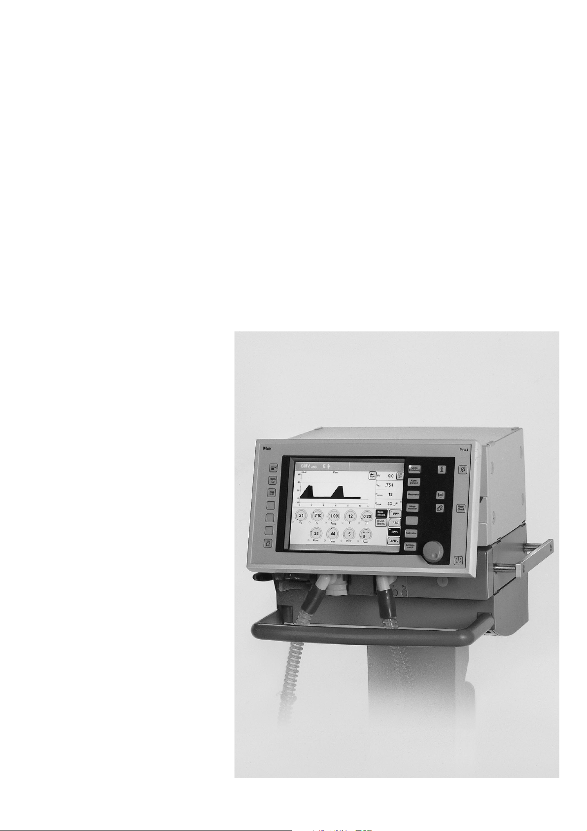
Evita 4
Intensive Care Ventilator
Instructions for Use
D
MEDICAL
Software 4.n
1-159-99
Page 2
Working with these Instructions for Use
Working with these Instructions for Use
Header line – the title...
of the main chapter
The title of the specific sub-section is printed underneath
the main header – to help you find your way quickly from
subject to subject.
Page body...
the Instructions for Use
in combined text/illustrations. The information is
expressed in the form of practical actions, giving the user
direct hands-on experience in learning how to use the
machine.
Left-hand column – the text...
provides explanations and instructs the user step-by-step
in the practical use of the product, with short, clear
instructions in easy-to-follow sequence.
Bullet points indicate separate actions. Where several
actions are described, numbers are used both to refer to
the relevant details in the illustrations and to specify the
sequence of actions.
Operation
Calibrating
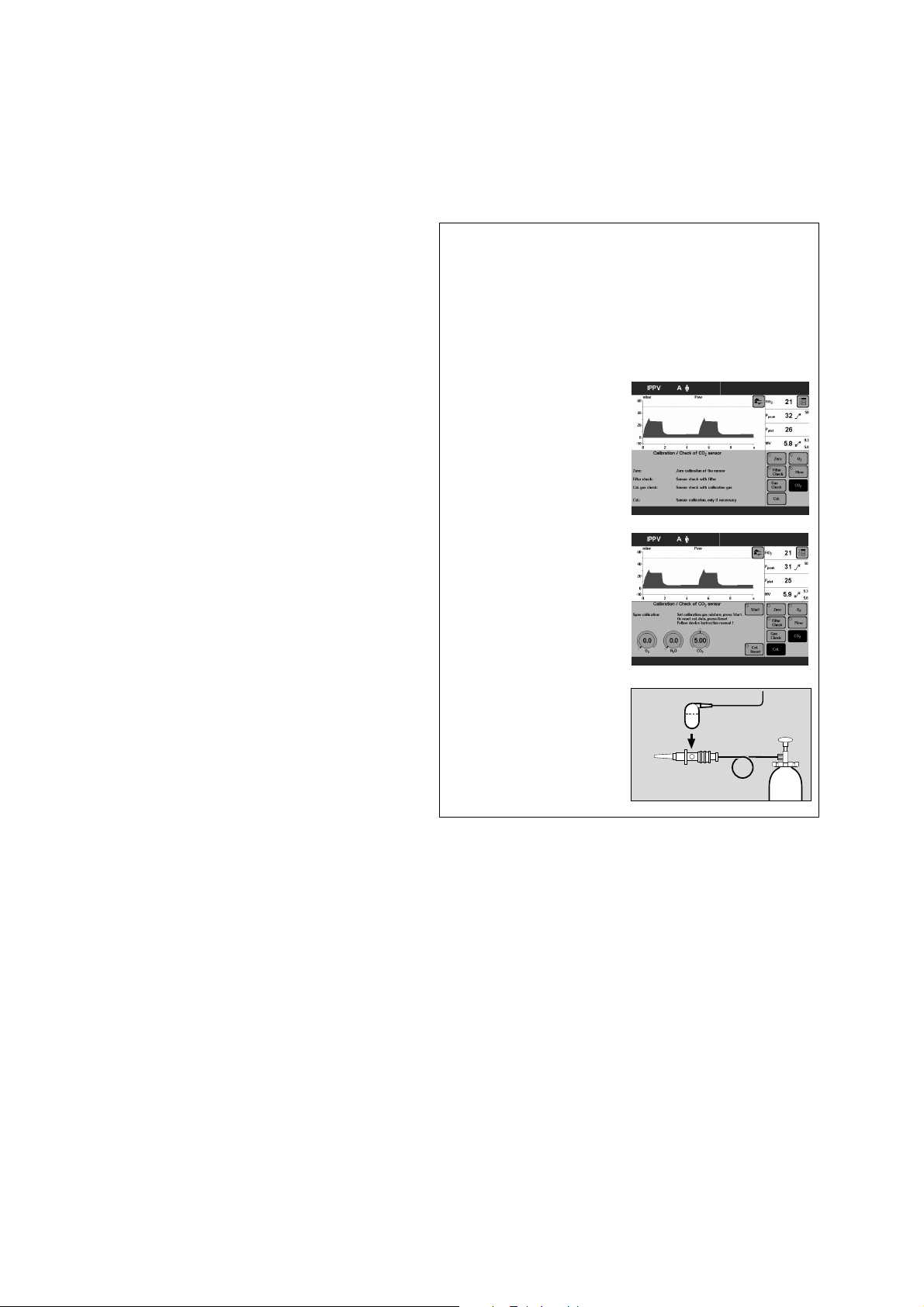
Calibrating the CO2 sensor
The CO2 sensor must be calibrated:
– if the check values are not met on checking
calibration with filter or calibration gas.
– as part of the half-yearly inspection of Evita 4.
● Switch on Evita 4. Wait about for 3 minutes for
the machine to complete its warm-up phase.
● Press the »Calibration« key.
Display (example):
● Touch »CO2« screen key.
Display (example):
● Carry out CO2 zero calibration, page 74.
After the CO2 zero calibration:
Touch the »Cal.« screen key.
Right-hand column – the illustrations...
provide the visual reference for the text and make it easier
to locate the various parts of the equipment. Elements
mentioned in the text are highlighted. Unnecessary details
are avoided.
Screen displays prompt the user to proceed and confirm
correct actions.
● Connect the calibration gas supply.
Use the cuvette from the calibration set!
1 Connect the calibration gas cylinder and the
cuvette of the calibration set to the hose.
2 Remove the CO2 sensor from its park bracket
and fit it to the cuvette of the calibration set.
● Read the CO2, O2 and N2O concentrations
(vol.%) of the calibration gas from the test
cylinder.
2
1
3
2
Page 3

What's new in Evita 4 software 4.n*
What's new in Evita 4 software 4.n
Specification of the humidifier used
– »Active humidifier«
or
– »HME/Filter« (artificial nose)
– for more accurate measurement of the volume
parameters
Apnoea ventilation On/Off
– can be selected as starting configuration
Extended range of settings for the alarm time
TApnoea >>
– from 5 to 60 seconds
Frequency can be reduced to 0
– for BIPAP and SIMV, for weaning without transitions
Ventilation mode BIPAPAssist
– for pressure-controlled assisted ventilation
>>
(formerly 15 to 60 seconds)
Additional weaning parameters
available as software version 4.n plus upgrade
in addition to the parameter occlusion pressure P 0.1
Evita 4.4n also determines the parameters
– RSB Rapid Shallow Breathing index
and
– NIF Negative Inspiratory Force index
External flow source
available as software version 4.n plus upgrade
– The amount of external flow is calculated by Evita 4.4n
(e.g. for additional tracheal gas insufflation) and
adjusts the volume monitoring tolerances in order to
avoid inadvertent alarms
Extended use of loop presentations
available as software version 4.n plus upgrade
– Loops can be zoomed and frozen
– Loops can be displayed permanently in the upper part
of the screen
Patient mode »prev. patient« can be selected
– to adopt the settings, including alarms, which were
effective before switching off the equipment
Leakage compensation On/Off
– for activation and deactivation of the automatic
leakage compensation function
Extended logbook entries
– Evita 4.4n identifies alarms which are active but not
displayed with an asterisk
Monitoring of tube blockages
– New alarm message »Tube blocked !!!«
Evita Remote (Remote Pad)
optionally available
– Remote control pad for parallel remote operation of
function keys on Evita 4
NIV
optionally available
– Application mode to support non-invasive ventilation
therapies
Nurse call
optionally available
– Connection for transmitting alarm signals to a central
hospital alarm station
* See pages 187 and 188 for new features in software
versions 2.n and 3.n
3
Page 4

4
Page 5

Contents
Contents
For Your Safety and that of Your Patients ..............................................11
Intended Medical Application.................................................................. 13
Operating Concept...................................................................................15
Structure of the Control Unit................................................................... 16
On-Screen Controls................................................................................. 17
Screen Keys for Function Selection
without Confirmation..................................................................................18
Screen keys for Function Selection,
Adjustment and Confirmation.....................................................................18
On-Screen Parameter Setting Knobs.........................................................20
Screen Pages...........................................................................................21
Standard page...........................................................................................22
»Adjustment« Screen Page........................................................................ 22
»Alarm Limits« Screen Page...................................................................... 24
»Measured values« Screen Page............................................................... 25
»Measurement Manoeuvre« Screen Page.................................................. 26
»Calibration« Screen Page.........................................................................26
»Configuration« Screen Page.....................................................................27
Positioning the Control Unit.....................................................................27
Ergonomic Positioning...............................................................................27
Preparation...............................................................................................29
Attaching components.............................................................................30
Fitting expiration valve................................................................................30
Fitting flow sensor..................................................................................... 30
Fitting O2 sensor capsule.......................................................................... 31
Note on Use of Heat and Moisture Exchanger (HME)............................. 31
Ventilation Adults and Children............................................................... 32
Connecting Aquapor humidifier..................................................................32
Connecting ventilation hoses..................................................................... 32
Fitting temperature sensor.........................................................................33
Fitting CO2 cuvette and CO2 sensor......................................................... 34
Ventilating Infants.................................................................................... 34
Fitting bacterial filter.................................................................................. 34
Fitting humidifier and ventilation hose.........................................................35
5
Page 6

Contents
Contents
If using bacterial filters............................................................................ 35
Supply and Connections..........................................................................36
Electrical power supply..............................................................................36
Note on use of a socket strip for ancillary equipment..................................36
Temporary interruption of power supply..................................................... 36
Gas supply................................................................................................37
Evita Remote (optional).............................................................................38
Connection................................................................................................38
Note automatic self-test............................................................................. 39
Nurse call (optional)..................................................................................40
Technical Data...........................................................................................40
Before Using for the First Time............................................................... 41
Selecting the language of the display texts.................................................41
Device Check...........................................................................................42
Before use on patient................................................................................ 42
Performing device check........................................................................... 43
Checking the hose system for leaks...........................................................46
Positioning the control unit......................................................................47
To position the control unit on the wall rail..................................................47
To position the control unit on the device................................................... 47
Operation................................................................................................. 49
Starting up............................................................................................... 50
Switching on............................................................................................. 50
Patient mode............................................................................................50
Selecting the patient mode........................................................................ 51
Entering the ideal body weight...................................................................51
Select the previous settings.......................................................................51
Starting ventilation..................................................................................... 52
Setting Ventilation Modes........................................................................53
IPPV..........................................................................................................53
SIMV, SIMV/ASB......................................................................................57
BIPAP, BIPAP/ASB.................................................................................. 60
BIPAPAssist................................................................................................62
CPAP, CPAP/ASB....................................................................................63
MMV, MMV/ASB...................................................................................... 65
APRV........................................................................................................ 67
Independent Lung Ventilation ILV............................................................69
Preparation................................................................................................69
Setting the master and slave device...........................................................71
6
Page 7

Contents
Contents
Apnoea ventilation................................................................................... 76
Setting Alarm Limits.................................................................................77
In the Event of an Alarm.......................................................................... 78
Cancel alarm tone..................................................................................... 79
Information J............................................................................................ 79
Displaying Curves and Measured Values................................................ 80
Displaying measured values.......................................................................81
Trends.......................................................................................................82
Loops........................................................................................................83
Reference curve displays...........................................................................83
Single stroke displays................................................................................83
Zoom loops (optional)................................................................................83
Display loops in the upper graphic area..................................................... 84
Logbook....................................................................................................85
Screen freeze............................................................................................86
Special Functions.....................................................................................87
Manual inspiration......................................................................................87
Exspiration Hold........................................................................................ 87
Medicament nebulisation........................................................................... 88
Oxygen enrichment for bronchial suction................................................... 91
Special measurement procedure: intrinsic PEEP........................................93
Special measurement procedure: occlusion pressure P 0.1....................... 94
Shut-down.................................................................................................95
Selecting Standby Mode..........................................................................96
Quitting Standby Mode..............................................................................96
Calibration................................................................................................97
Calibrating O2 sensor................................................................................97
Calibrating flow sensor..............................................................................98
External flow source.................................................................................. 99
Checking/calibrating CO2 sensor............................................................100
CO2 zero checking................................................................................. 100
Testing CO2 calibration with test filter..................................................... 102
Testing CO2 calibration with test gas...................................................... 103
Calibrating CO2 sensor...........................................................................105
Resetting CO2 calibration........................................................................106
Configuration......................................................................................... 107
Sound.....................................................................................................108
Adjusting the volume of the alarm tone.....................................................108
7
Page 8

Contents
Contents
Screen....................................................................................................109
Selecting displayed measured values.......................................................109
Selecting displayed curves...................................................................... 111
Selecting displayed trends.......................................................................112
Ventilation.............................................................................................. 113
Selecting ventilation modes..................................................................... 113
Selecting Pmax pressure limit..................................................................115
Selecting AutoFlow as start-up ventilation mode....................................116
Apnoea ventilation On/Off....................................................................... 117
Selecting patient mode............................................................................118
Start-up values for ventilation parameters and alarm limits........................119
Setting start-up values for ventilation parameters »VT, f«...........................119
Setting start-up values for ventilation parameters »Pressure, O2, I:E«....... 121
Leakage compensation On/Off................................................................122
Setting start-up values for alarm limits......................................................123
System Defaults.....................................................................................124
Setting external interface......................................................................... 124
Setting time and date.............................................................................. 125
Setting language and units...................................................................... 125
Service diagnosis....................................................................................126
Troubleshooting.....................................................................................127
Preparing............................................................................................... 135
Dismantling............................................................................................136
CO2 sensor (optional)............................................................................. 136
Temperature sensor................................................................................ 136
Medicament nebuliser............................................................................. 137
Ventilation hoses..................................................................................... 137
Flow sensor............................................................................................ 137
Expiration valve........................................................................................138
Humidifier................................................................................................138
Disinfecting/Cleaning............................................................................ 139
Assembling............................................................................................ 142
Fitting expiration valve............................................................................. 142
Before Reusing on Patient.....................................................................143
Maintenance Intervals ...........................................................................143
Clean or replace cooling air filter............................................................. 144
Disposing of batteries and O2 sensors.................................................... 144
Removing/fitting ambient air filter.............................................................144
Correct disposal of apparatus................................................................. 145
8
Page 9

Contents
Contents
What's what........................................................................................... 147
Control unit............................................................................................. 148
Front connections................................................................................... 149
Back panel..............................................................................................150
Technical Data....................................................................................... 151
Environmental conditions.........................................................................152
Settings.................................................................................................. 152
Performance data....................................................................................153
Measured value displays..........................................................................153
Monitoring...............................................................................................155
Operating data........................................................................................ 156
Machine outputs......................................................................................157
Electromagnetic compatibility (EMC)....................................................... 158
Classification...........................................................................................158
UMDNS-Code........................................................................................ 158
Materials used.........................................................................................158
Description.............................................................................................159
Ventilation Modes.................................................................................. 160
Volume-controlled ventilation with PLV and AutoFlow............................ 160
Classic volume constant mandatory ventilation stroke.............................. 160
Manual pressure limiting with Pmax ........................................................ 160
AutoFlow.............................................................................................. 161
Start-up procedure with AutoFlow.........................................................162
Sigh........................................................................................................ 163
SIMV.......................................................................................................164
ASB........................................................................................................165
BIPAP.....................................................................................................166
BIPAPAssist............................................................................................. 167
APRV......................................................................................................168
MMV.......................................................................................................168
Flow measurement..................................................................................170
Compensation of the effect of hose system compliance...........................170
Conversion according to ambient conditions............................................170
Automatic leakage compensation.............................................................172
Weaning parameters............................................................................... 174
Occlusion pressure P 0.1........................................................................174
Rapid Shallow Breathing RSB.................................................................175
Negative Inspiratory Force NIF................................................................ 175
Intrinsic PEEP......................................................................................... 176
Insp. O2 concentration during medicament nebulisation...........................177
9
Page 10

Contents
Contents
Abbreviations......................................................................................... 178
Symbols................................................................................................. 181
Bibliography...........................................................................................182
Parts List................................................................................................ 183
Order List............................................................................................... 185
What was new in Evita 4 software 2.n................................................... 187
What was new in Evita 4 software 3.n................................................... 188
Index...................................................................................................... 189
10
Page 11

For Your Safety and that of Your
Patients
For Your Safety and that of Your Patients
Strictly follow the Instructions for Use
Any use of the apparatus requires full understanding and
strict observation of these instructions. The apparatus is
only to be used for purposes specified here.
Maintenance
The apparatus must be inspected and serviced regularly
by trained service personnel at six monthly intervals
(and a record kept).
Repair and general overhaul of the apparatus may only be
carried out by trained service personnel.
We recommend that a service contract be obtained with
DrägerService and that all repairs also be carried out by
them. Only authentic Dräger spare parts may be used for
maintenance.
Observe chapter "Maintenance Intervals".
Accessories
Do not use accessory parts other than those in the order
list.
Liability for proper function or damage
The liability for the proper function of the apparatus is
irrevocably transferred to the owner or operator to the
extent that the apparatus is serviced or repaired by
personnel not employed or authorized by DrägerService
or if the apparatus is used in a manner not conforming to
its intended use.
Dräger cannot be held responsible for damage caused
by non-compliance with the recommendations given
above. The warranty and liability provisions of the terms
of sale and delivery of Dräger are likewise not modified
by the recommendations given above.
Dräger Medical AG & Co. KGaA
Not for use in areas of explosion hazard
This apparatus is neither approved nor certified for use in
areas where combustible or explosive gas mixtures are
likely to occur.
Safe connection with other electrical equipment
Electrical connections to equipment which is not listed in
these Instructions for Use should only be made following
consultations with the respective manufacturers or an
expert.
11
Page 12

For Your Safety and that of Your Patients
Safe use of the equipment
Safe use of the equipment
This equipment must only be used under the
supervision of qualified medical staff, so that help is
available immediately if any faults or malfunctions
occur.
This equipment must not be used with flammable
gases or anaesthetic agents. Danger of fire!
Do not use mobile telephones within 10 metres of
ventilators!
Mobile telephones may impair the functioning of
electromedical equipment and endanger the patient1).
Appropriate ventilation monitoring
The built-in monitoring facilities of Evita 4 ensure
appropriate monitoring of ventilation therapy and therefore detect any undesirable changes in the following
ventilation parameters:
– Airway pressure, Paw
– Expiratory minute volume, MV
– Inspiratory O2 concentration, FiO2
– Inspiratory breathing gas temperature, T
– Expiratory CO2 concentration, etCO2 (optional)
– Inspiratory breathing volume, VTI
– Apnoea time
– Tachypnoea monitoring
Back-up ventilation with an independent manual
ventilation device
If a fault is detected in Evita 4 so that its life-support
functions are no longer assured, ventilation using an
independent ventilation device must be started without
delay – if necessary with PEEP and/or increased
inspiratory O2 concentration (e.g. with the Dräger
Resutator 2000).
Changes in these parameters may be caused by:
– Acute changes in the patient's condition
– Incorrect settings and faulty handling
– Equipment malfunctions
– Failure of power and gas supplies
If a fault occurs in this equipment, separate measuring
instruments should be used.
1) Dräger medical equipment meets the requirements for immunity to
interference in accordance with the specific product standards and
EN 60601-1-2 (IEC 601-1-2). Depending on the type of mobile
telephone used and on the application situation, however, field
strengths exceeding the values specified in the applicable standards
may develop in the immediate vicinity of the mobile telephone and
therefore lead to faults and malfunctions.
12
Page 13

Intended Medical Application
Contents
Intended Medical Application
Contents
Intended Medical Application.................................................................. 14
13
Page 14

Intended Medical Application
Intended Medical Application
Long-term ventilator for intensive care.
For adults, children and neonates.
For premature babies with the "NeoFlow" option.
With the following ventilation modes:
IPPV Intermittent Positive Pressure Ventilation,
controlled and assisted constant-volume ventilation.
With the options:
– CPPV (Continuous Positive Pressure Ventilation)
– PLV (Pressure Limited Ventilation)
– AutoFlow
for automatic regulation of inspiration flow
– IRV (Inversed Ratio Ventilation)
SIMV Synchronized Intermittent Mandatory Ventilation,
procedure for weaning patients off the ventilator after
they have started spontaneous breathing.
With the options:
– PLV (Pressure Limited Ventilation)
– AutoFlow
for automatic regulation of inspiration flow.
MMV Mandatory Minute Volume Ventilation,
spontaneous breathing with automatic adjustment of
mandatory ventilation to the patient's minute volume
requirement.
With the options:
– PLV (Pressure Limited Ventilation)
– AutoFlow
for automatic regulation of inspiration flow.
BIPAPAssist (Biphasic Positive Airway Pressure Assisted)
Pressure-controlled assisted ventilation
APRV Airway Pressure Release Ventilation,
Spontaneous breathing on two pressure levels with long
time ranges – independently adjustable.
Special modes:
Apnoea Ventilation
For switching over automatically to
volume-controlled mandatory ventilation, if breathing
stops.
If apnoea occurs, Evita 4 emits an alarm after the preset
alarm period (TApnoea > ) and starts volume-controlled
ventilation.
ILV Independent Lung Ventilation,
Separate, differentiated, synchronised ventilation with
two Evita units, one for each lung.
Diagnostics:
Intrinsic PEEP-measurement
for determining intrinsic PEEP and measuring trapped
volume.
Occlusion pressure measurement
for evaluating breathing drive during spontaneous
breathing.
SB Spontaneous Breathing,
Spontaneous breathing at ambient pressure.
CPAP Continuous Positive Airway Pressure,
Spontaneous breathing with positive airway pressure.
ASB Assisted Spontaneous Breathing,
pressure-assisted spontaneous breathing.
BIPAP* Biphasic Positive Airway Pressure,
Pressure-controlled ventilation combined with free
spontaneous breathing during the complete breathing
cycle, and adjustable pressure increase to CPAP level.
–––––––––––
* Registered trade mark
With monitoring for:
airway pressure, Paw
expiratory minute volume, MV
inspiratory O2 concentration, FiO2
inspiratory breathing gas temperature, T
expiratory CO2 concentration, etCO2
inspiratory breathing volume, VTI
apnoea time
tachypnoea monitoring to detect rapid, shallow
spontaneous breathing
Automatic gas switch-over.
In the event of a gas failure, the change-over to another
gas is automatic.
14
Page 15

Operating Concept
Contents
Operating Concept
Contents
Structure of the Control Unit.................................................................. 16
On-Screen Controls................................................................................ 17
Screen Keys for Function Selection
without Confirmation................................................................................ 18
Screen keys for Function Selection,
Adjustment and Confirmation....................................................................18
On-Screen Parameter Setting Knobs........................................................20
Screen Pages..........................................................................................21
Standard page......................................................................................... 22
»Adjustment« Screen Page....................................................................... 22
»Alarm Limits« Screen Page..................................................................... 24
»Measured values« Screen Page.............................................................. 25
»Measurement Manoeuvre« Screen Page................................................. 26
»Calibration« Screen Page........................................................................26
»Configuration« Screen Page....................................................................27
Positioning the Control Unit....................................................................27
Ergonomic Positioning..............................................................................27
15
Page 16
Operating Concept
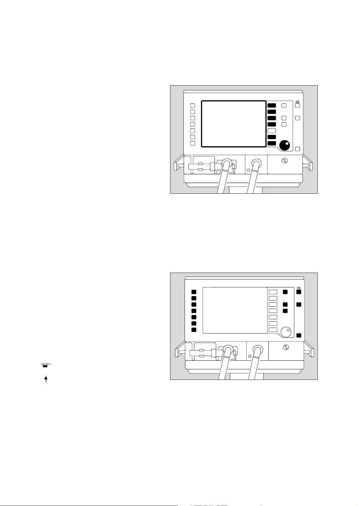
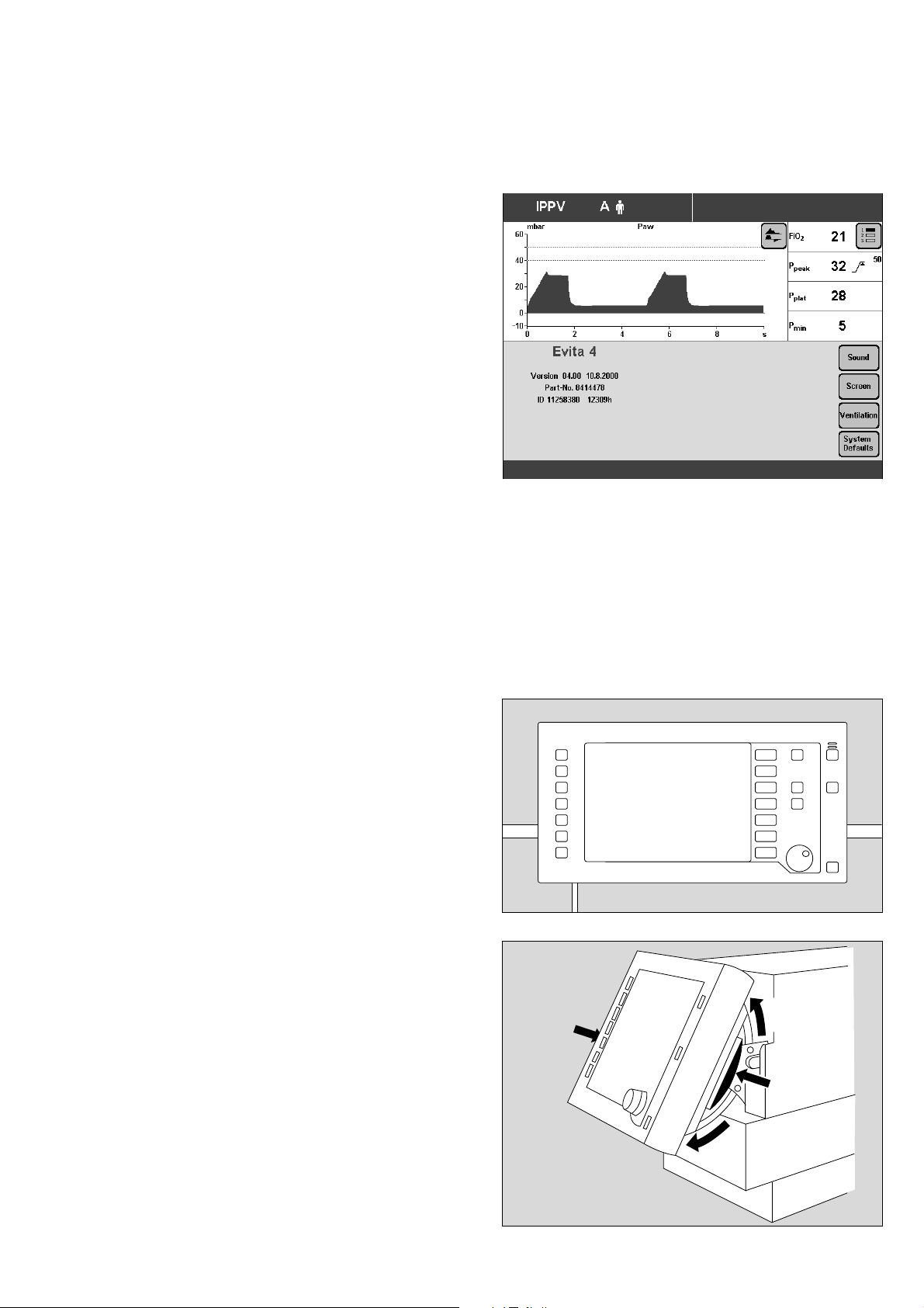
Structure of the Control Unit
Structure of the Control Unit
The main components of the control unit are the screen,
a set of fixed function keys and the central rotary dial-
knob.
The function keys are used to call up the screen pages
appropriate to the application.
In addition to curves, measured values and status
displays, the screen contains, in a separate field, touchsensitive keys and touch-sensitive rotary knobs for
parameter setting.
The touch-sensitive screen keys and the screen knobs
are used in a similar way to ordinary keys and knobs:
D Evita 4
Touching with the fingertip is equivalent to pressing a key
or taking hold of a knob.
The display always contains only the screen keys and
screen knobs required for function selection and/or
adjustment.
Settings and confirmations are made by turning and
pressing the central, rotary knob.
The keys for routine functions are placed to the right and
left on the outside of the front panel.
Frequently used function keys are placed on the right,
e.g.
the key »? « for selecting the standard page
or the »Alarm Reset« key for resetting or confirming
messages.
Less frequently used function keys are placed on the lefthand side of the front panel,
e.g.
the key » « for switching the medicament nebuliser
on/off,
or the »O2 suction« key for bronchial suctioning.
D Evita 4
16
Page 17
The power switch
for switching the device on/off.
The power switch is located on the back panel and has a
pivoting cover to protect against being inadvertently
switched off.
Operating Concept
Structure of the Control Unit
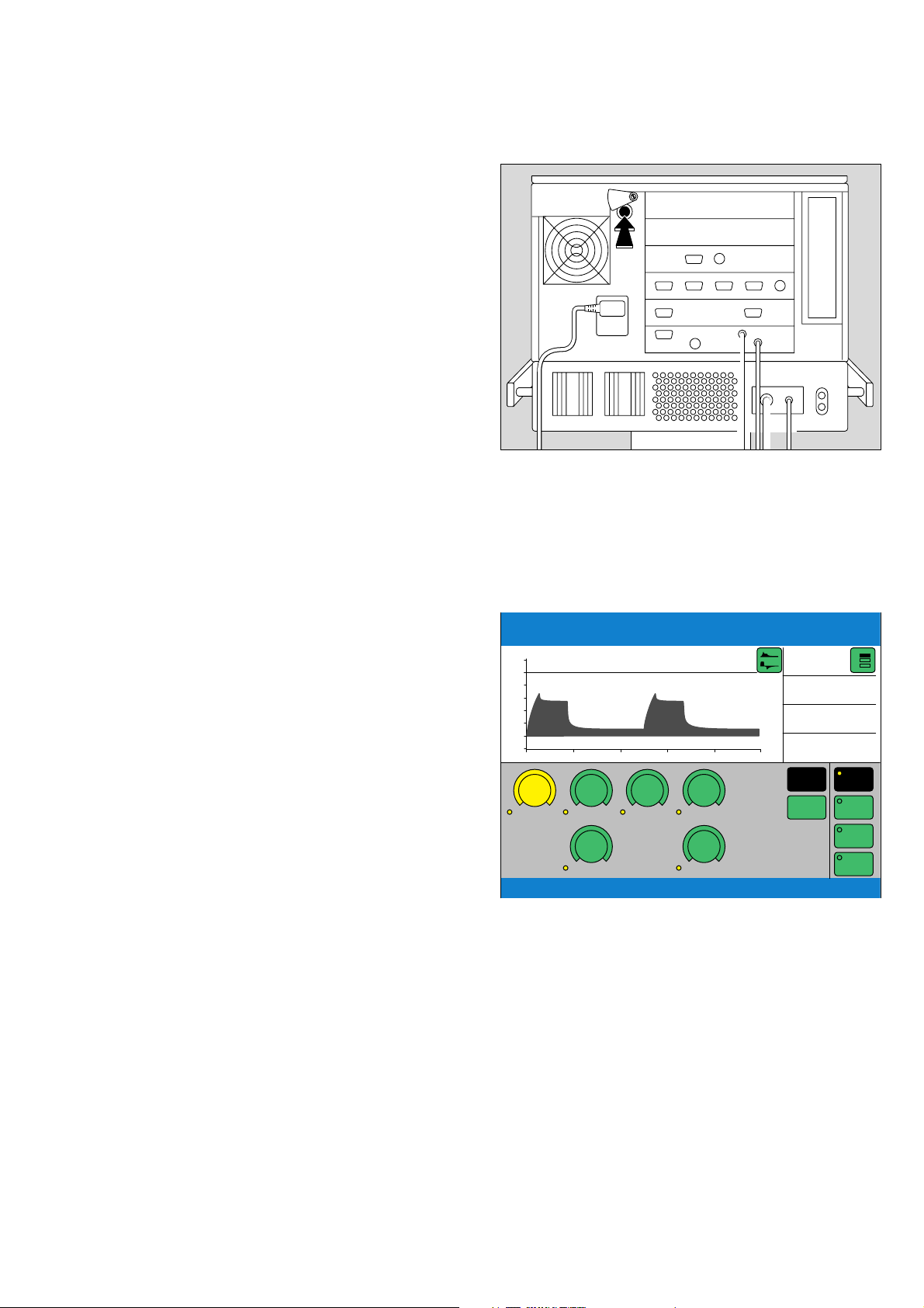
On-Screen Controls
On-Screen Controls
The lower half of the screen contains touch-sensitive
coloured screen keys and screen knobs.
Touching these controls with the fingertip is equivalent to
pressing key or taking hold of a knob.
The colour displays the status of the "control" and
"LEDs":
green = usable
white = not usable
yellow = adjust/confirm
black = effective function/display
IPPV
60
40
20
0
-10
O2 [%]
A
Assist
[mbar]
P
aw
0 2 4 6 8 t [s]
21
.500
VT
60
Flow
m
1.7
Tinsp
21
f
5
PEEP
FiO2 21
P
33 >
peak
P
27
plat
MV 5.3 _
Basic
settings
Extra
settings
IPPV
BIPAP
SIMV
ASB
1
2
3
50
7.0
4.0
17
Page 18
Operating Concept
On-Screen Controls
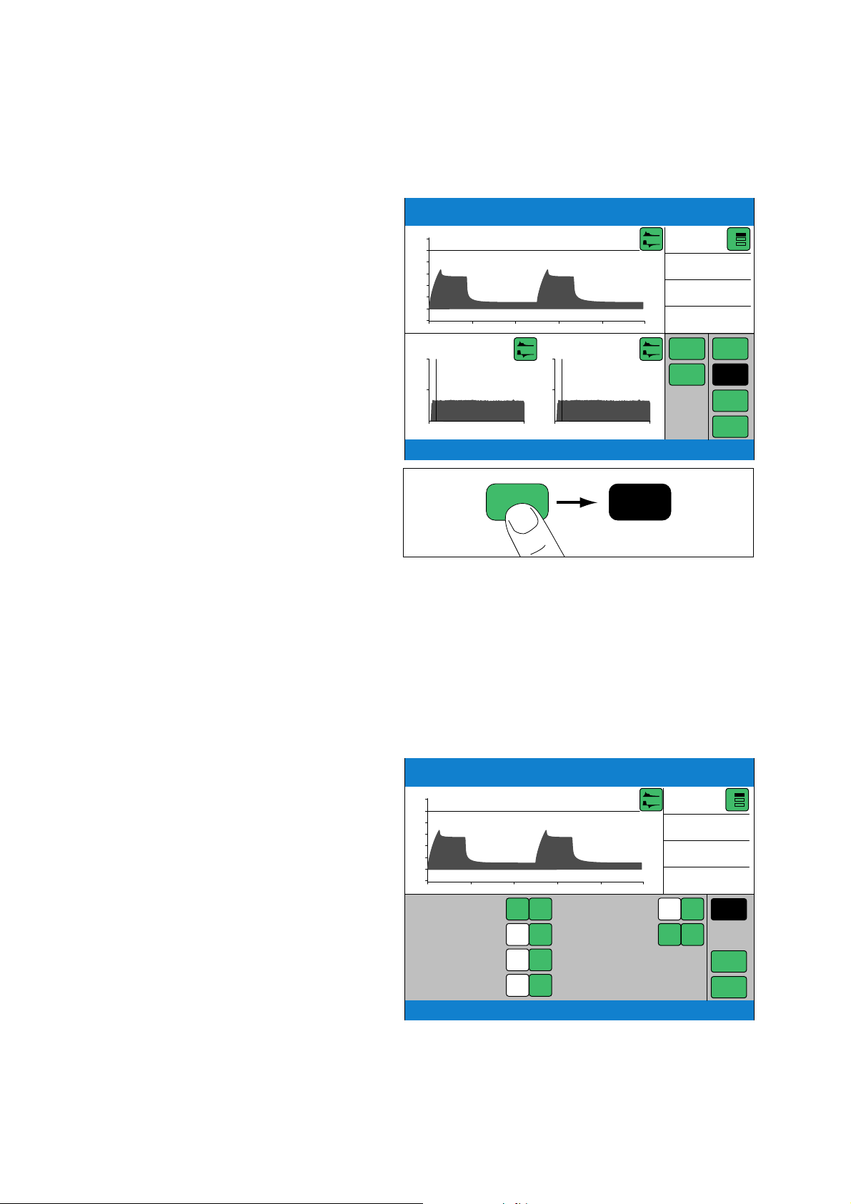
Screen Keys for Selecting Functions without
Confirmation
e.g. for paging through the system on-screen
for changing the menu
for switching over displays
example:
● Press the »Table« key = select display.
The key goes black to show that the function is active.
IPPV
60
40
20
0
-10
20
10
0
11:03 12:03
A
Assist
[mbar]
P
aw
0246
MV
11:06 total 1.5
spon 0.0
m
40
20
0
11:03 12:03
Table Table
8 t [s]
f
11:06 total 1.5
spon 0.0
FiO2 21
P
33 >
peak
P
27
plat
MV 5.3 _
Zoom in
Zoom out
Table
Trends
Loops
Logbook
1
2
3
50
7.0
4.0
Screen Keys for Function Selection,
Adjustment and Confirmation
Display (example):
IPPV
60
40
20
0
-10
MV 5.3 L/min
f
spn
V
Ti
P
aw
A
P
[mbar]
aw
0 2 4 6 8 t [s]
0.0 bpm
.497 L
33 L/min
m
7.0
4.0
_
_
_
_
30
780
50
T
Apnoea
etCO
s
– – mmHg
2
FiO2 21
P
33 >
peak
P
27
plat
MV 5.3 _
15
_
100
_
0
Monitoring
Logbook
Limits
1
2
3
50
7.0
4.0
18
Page 19
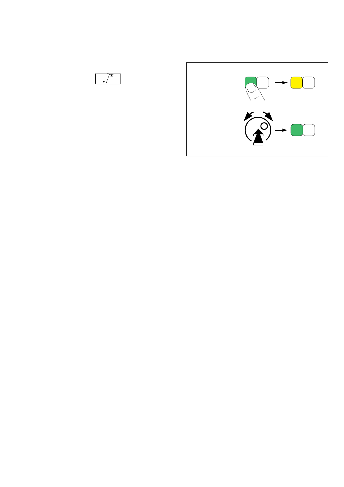
1 Touch the relevant screen key for the alarm limits,
e.g.:
MV 2.3 L/min
9.3
3.1
The colour changes from green to yellow = setting
function is set.
Operating Concept
On-Screen Controls
1
MV 2.3 L/min
2 Turn the rotary knob = adjust the alarm limit.
The value is displayed in the screen key.
3 Press the rotary knob = the colour changes from
yellow to green, and the set alarm limit is confirmed
and effective.
To cancel the setting:
● Touch the screen key again
or
● touch another screen key.
2
3
19
Page 20
Operating Concept
On-Screen Controls
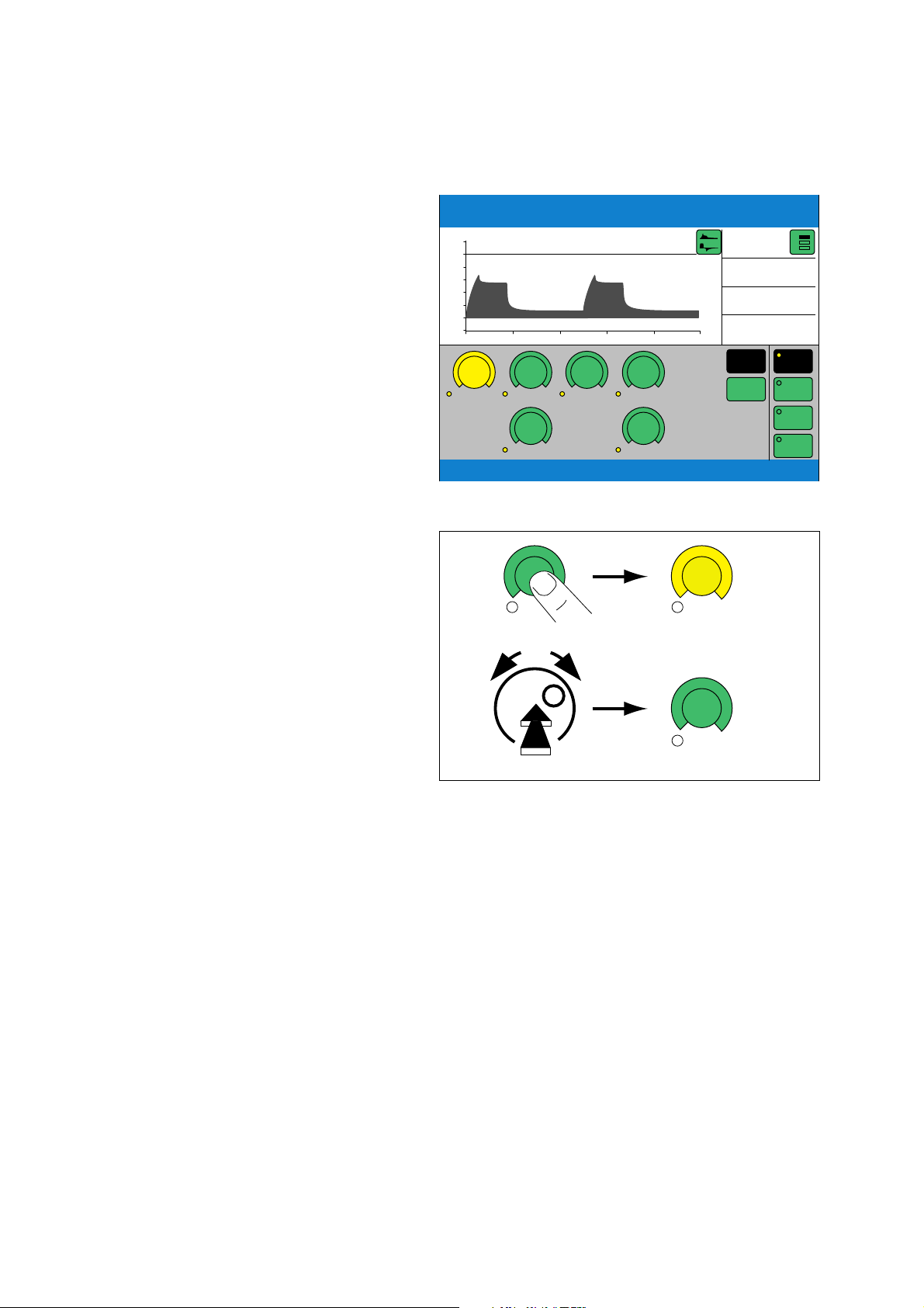
Screen Knobs for Setting Parameters
Display (example):
e.g. »PEEP« screen knob.
1 Touch the »PEEP« screen knob:
It changes colour from green to yellow =
setting function selected.
2 Turn rotary knob = Adjust setting. The value is
displayed in the knob.
3 Press rotary knob = Confirm. The knob changes
colour from yellow to green, and the setting is
validated and takes effect.
IPPV
60
40
20
0
-10
O2 [%]
A
Assist
[mbar]
P
aw
0 2 4 6 8 t [s]
21
.500
VT
60
Flow
m
1.7
Tinsp
21
f
5
PEEP
1
PEEP
2
FiO2 21
P
33 >
peak
P
27
plat
MV 5.3 _
Basic
settings
Extra
settings
5
PEEP [mbar]
10
1
2
3
IPPV
BIPAP
SIMV
ASB
50
7.0
4.0
While pressure values, such as Pmax, are being set, they
are displayed in the Paw (t) curve as a dashed black line.
To cancel the setting:
● Press the screen knob again
or
● press another screen knob.
PEEP [mbar]
3
20
Page 21

Screen Pages
Operating Concept
Screen Pages
All the screen pages have the same structure, i.e. their
contents are always arranged in the same positions on
the screen:
Messages indicating ventilation modes and alarms,
displays of measured values and curves, and help
functions, always appear in the same position on the
screen:
➀ The active ventilation mode/patient mode is
displayed on the left-hand side of the top line.
The ventilation mode is indicated by its abbreviation,
e.g. BIPAP.
The patient mode is indicated by a symbol:
A m for adults
P m for paediatric
In the case of spontaneous breathing activity by the
patient, a lung symbol ⁄ is briefly displayed as
indicator.
➁ Curves are displayed in the upper left-hand quarter of
the screen.
➂ The lower half of the screen shows curves and
measured values or screen keys and screen knobs –
depending which screen page is selected.
Current ventilation mode/patient mode Alarms
➀
Curves Measured
➁
Curves or screen knobs Measured
➂
Help functions
➅
➃
values
values or
screen keys
➄
➃ Alarms are displayed on the right of the top line.
➄ Measured values are displayed in the upper right-
hand quarter of the screen.
➅ Help functions appear in the bottom line of the
screen. On the right, Evita 4 provides setting
instructions. On the left, Evita 4 provides information
on the current status – this information can be
accessed by pressing key » «
The solid function keys to the right of the screen are used
to select the screen pages for the following specific
application situations:
– Settings
– Alarm limits
– Measured values
– Special measurement procedures
– Calibration
– Configuration
D Evita 4
21
Page 22
Operating Concept
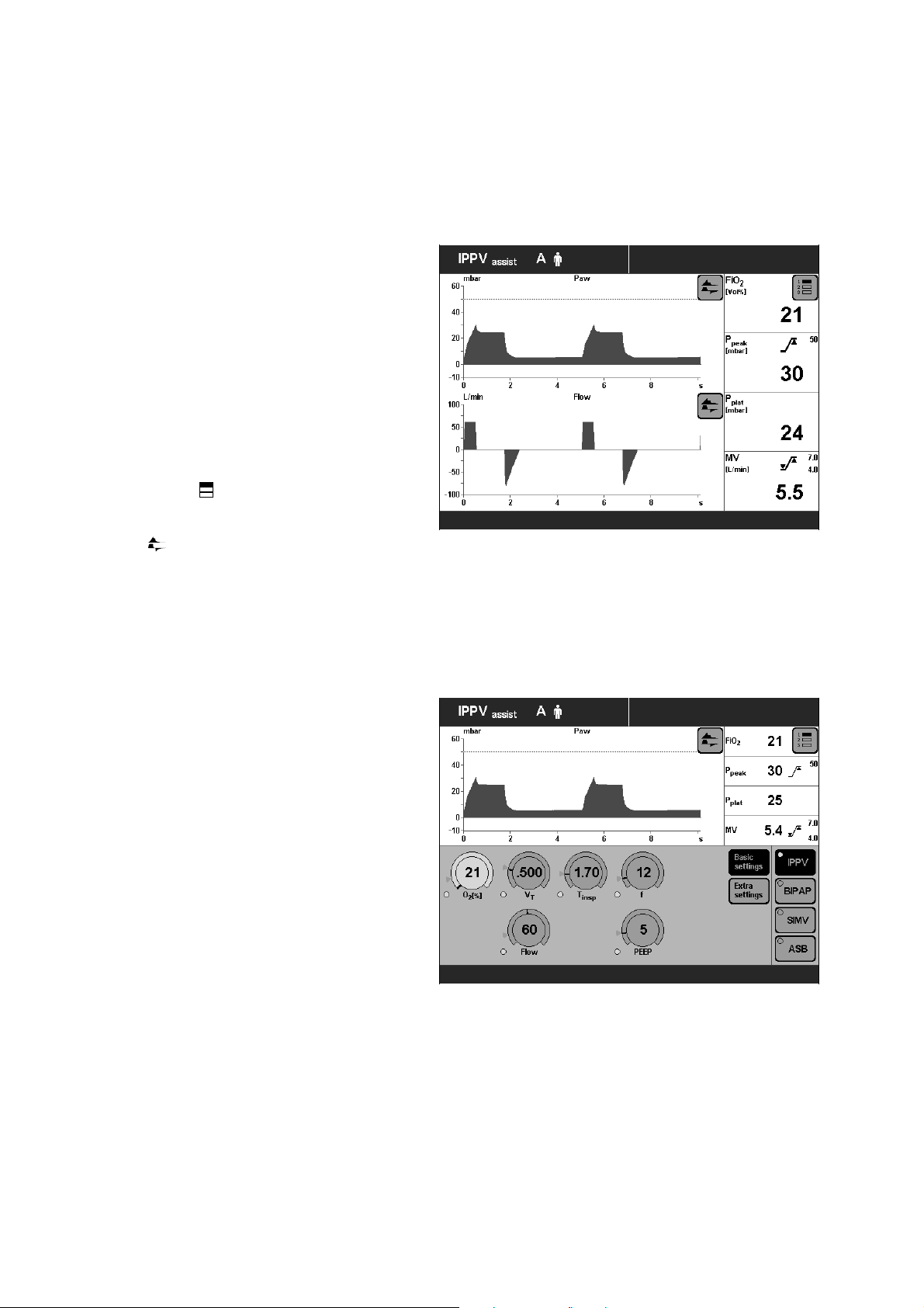
Screen Pages
Screen page
For displaying the ventilation status
● Press »? « key.
Display (example):
The standard page shows the ventilation situation at a
glance – reduced to the most important measurement
parameters and curves.
Four measured values are shown on the right, and two
curves on the left.
Other measured values and curves can be selected in
the standard page and all subsequent screen pages.
To select other measured value combinations:
1
● Touch screen key » « repeatedly.
2
3
To select other curves:
● Touch key » «, and touch the screen key
corresponding to the desired curve.
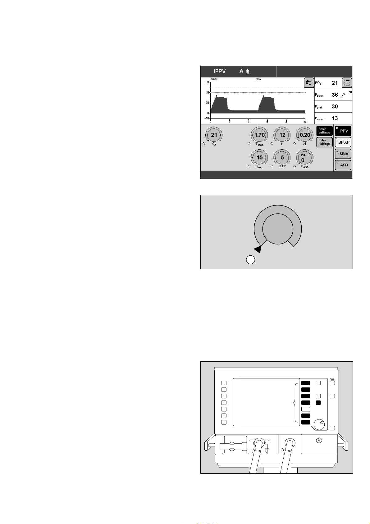
»Settings« screen
For displaying the setting parameters.
The bottom right-hand side of the screen contains the
screen keys for selecting the ventilation modes.
The screen key displayed in black (IPPV in the example)
represents the currently activated ventilation mode.
The bottom left-hand side of the screen contains the on-
screen rotary control knobs.
The values of the setting parameters are displayed in the
screen knobs relevant to the ventilation mode.
The user-definable start-up settings are marked by an
arrow (j) on the scales of the screen knobs. See
"Configuration" on page 107 onwards.
012 37 207 01337 207
Changing the settings of an active ventilation mode
● Touch the appropriate screen knob, which will change
colour from green to yellow = setting function
enabled.
● Turn the rotary knob on the control unit = adjustment
of the value of setting in the screen knob.
● Press the rotary knob: the screen knob changes
colour from green to yellow = the setting is confirmed
(validated) and active.
22
Page 23
Selecting another ventilation mode and setting its
parameters
● Touch the appropriate screen key, e.g. »BIPAP«. The
key changes colour from green to yellow, and the
parameter setting page for BIPAP is displayed.
To set the parameters for BIPAP:
● Touch the screen knob, which changes colour from
green to yellow = adjustment function selected.
● Turn rotary knob = adjust value displayed in screen
knob.
Operating Concept
Screen Pages
● Press rotary knob: the screen knob changes colour
from yellow to green = setting validated and effective.
If the indicator "LED" next to a screen knob is illuminated
white, the knob setting will only be effective after the new
ventilation mode has been switched on (example: »PASB«
knob).
If the indicator "LED" is illuminated yellow, the relevant
knob setting is already active in the existing ventilation
mode (example: »O2« knob).
The start-up values effective on switching on the
ventilator are marked on the relevant knob-scale with an
arrow (j).
Example: PASB = 0 mbar
● Press the rotary knob: the screen key changes colour
from yellow to black = the ventilation mode is active.
For detailed instructions on setting the ventilation modes,
please refer to page 49.
Cancel selection/setting
014 37 207
PEEP +
10
PASB
● Press the screen key or screen knob again.
or
● Press another screen key or another screen knob.
To quit a screen page:
1 Press »? « key = return to standard page
or
2 press any of the function keys next to the screen on
the right.
D Evita 4
2
1
23
Page 24
Operating Concept
Screen Pages
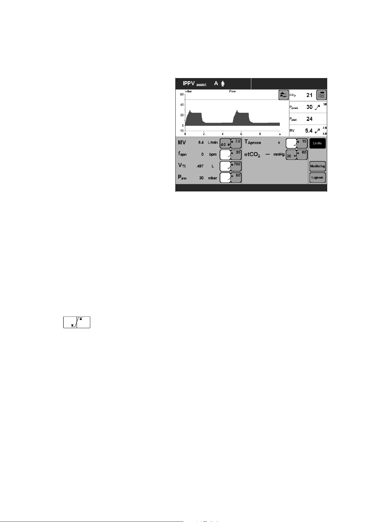
»Alarm limits« Screen Page
This page is used for:
Displaying the measured values and the corresponding
alarm limits.
Setting the alarm limits.
Setting the monitoring function.
Displaying the logbook.
The alarm limits are grouped together in a field and
combined with a curve and four measured values.
Limits, monitoring and logbook are selected by the
screen keys on the right of the screen.
The currently activated screen key is highlighted in black.
017 37 207
Displaying/Setting Alarm Limits
● Touch the »Limits« screen key. The screen key will
change to black.
The monitored measured values will be displayed,
together with their alarm limits:
Example:
MV 5.4 L/min
5.5
7.5
Left-hand screen key = lower alarm limit.
Right hand screen key = upper alarm limit.
Set the alarm limit:
● Touch the relevant screen key.
The key changes colour to yellow = adjustable.
● Turn the rotary knob = adjust value displayed in the
key.
● Press the dial-knob. The screen key changes colour
to green = setting confirmed.
The alarm limit is now effective.
For detailed operating instructions, please refer to
page 77.
24
Page 25
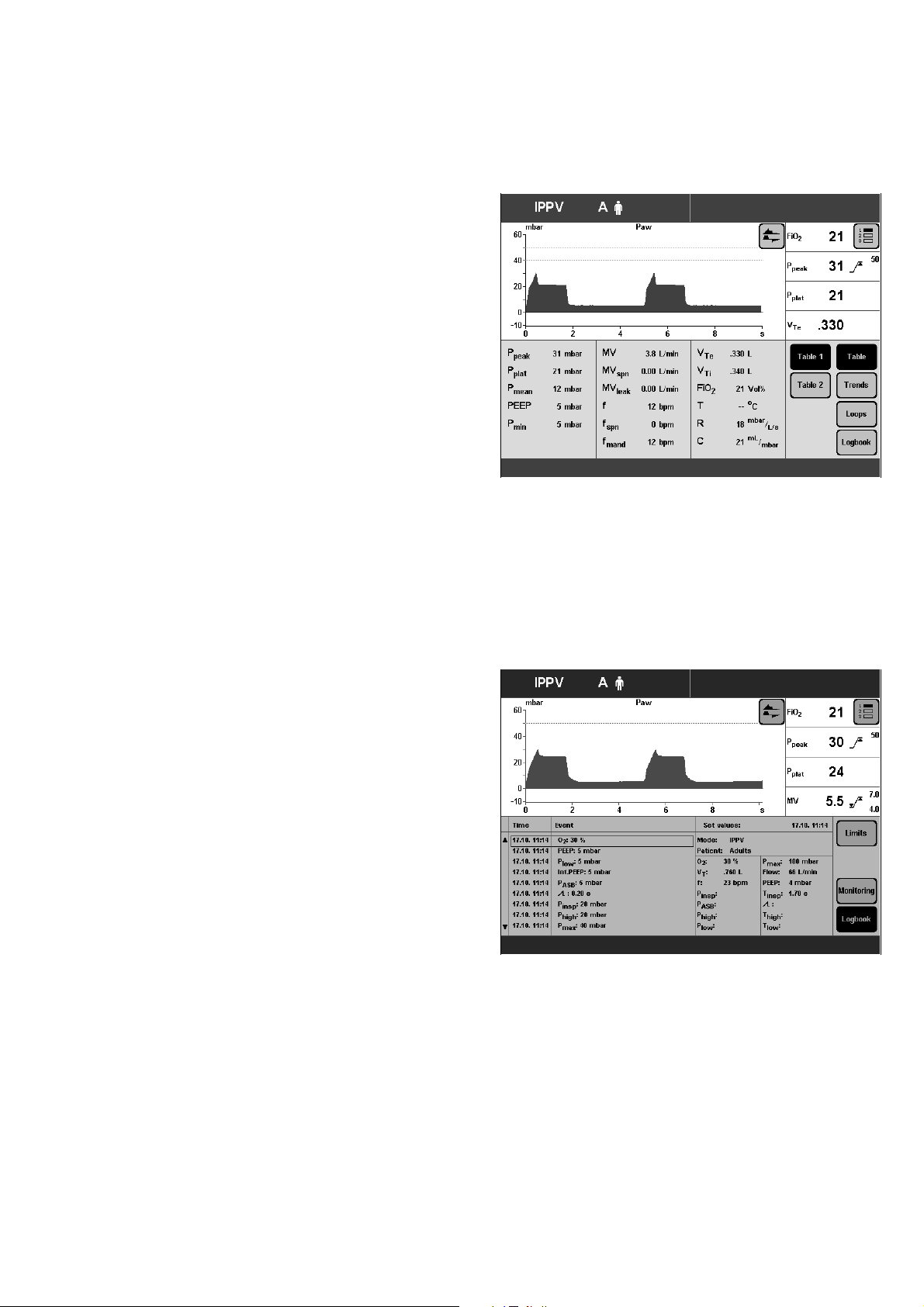
»Measured values« Screen Page
This page is used to display:
– the measured values in table format
– the trend curve
– loops
– logbook.
Tables, trend, loop and logbook are selected by the righthand block of screen keys.
Example table of measured values »Table 1«
For detailed operating instructions, please refer to
page 81.
Operating Concept
Screen Pages
018 37 207019 37 207
Display Logbook
● Touch the »Logbook« screen key.
● Turn the dial-knob = select alarm events.
For detailed operating instructions, please refer to
page 85.
25
Page 26
Operating Concept
Screen Pages
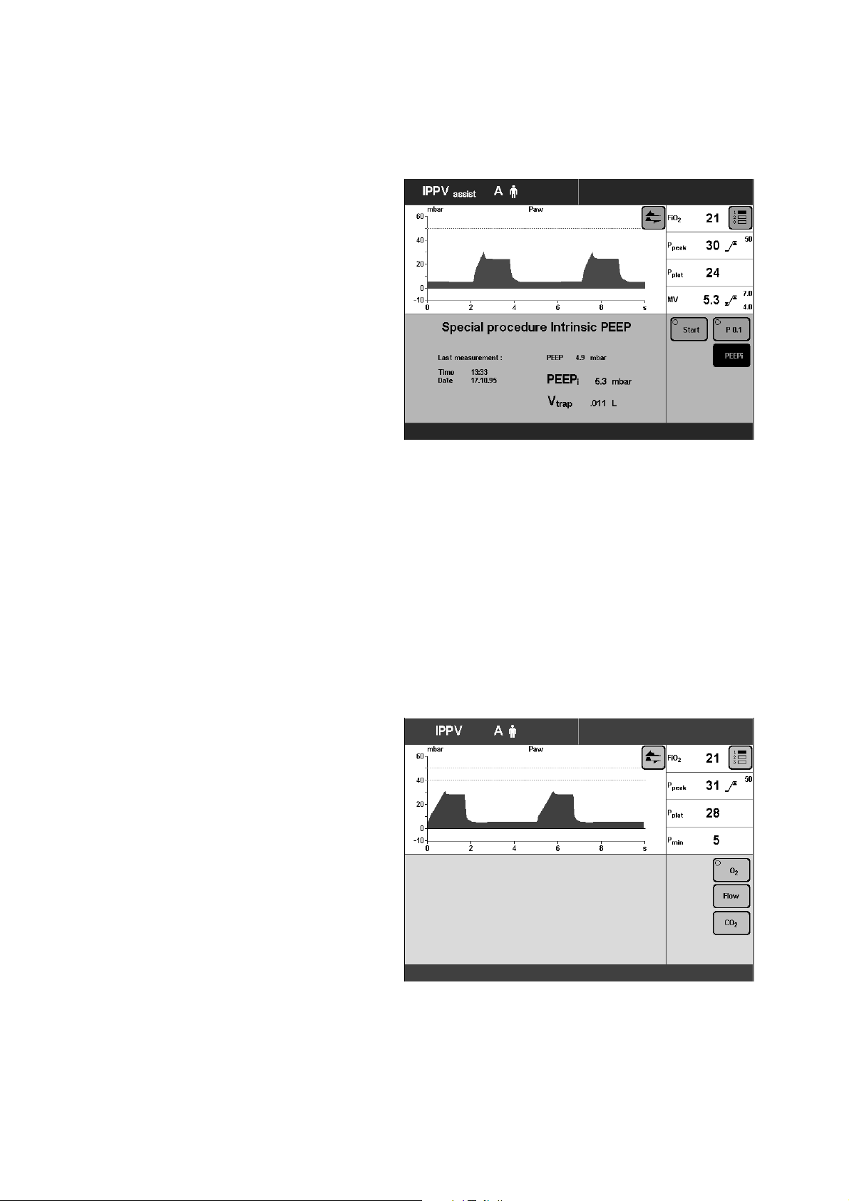
»Special Procedures« Screen Page
This page is used to display and perform the following
special measuring procedures:
– Intrinsic PEEP
and
– Occlusion pressure P 0.1
The desired special procedure is selected by the
appropriate screen key on the right. The result of the last
special procedure is displayed.
Example: Intrinsic PEEP:
To start the special procedure:
● Touch the »Start« screen key.
For detailed operating instructions, please refer to
page 93 and 94.
»Calibration« Screen Page
This page is used for calibrating
– the O2 sensor
– the Flow sensor
– the CO2 sensor
● Select the desired sensor with the »O2«, »Flow« or
»CO2« screen keys.
Calibration starts as soon as the relevant key is
pressed.
020 37 207021 37 207
Evita 4 provides the necessary calibration instructions in
the Help Function line at the bottom of the screen.
For detailed operating instructions, please refer to
page 97 et seq..
26
Page 27
»Configuration« Screen Page
For selecting/adjusting the following functions:
Sound
Setting the volume of the alarm tone.
Screen
Selecting the displayed measured values.
Selecting the displayed curves.
Selecting the displayed trends.
Ventilation
Selecting ventilation modes.
Selecting the patient mode.
Selecting the initial setting.
System Defaults
Setting the external interface.
Setting the time and date.
Selecting the language and measurement units.
Selecting service diagnosis.
Operating Concept
Screen Pages
Control Unit Location
022 37 207
For detailed operating instructions, see page 107.
Control Unit Location
To adapt to the situation of the ventilation location, the
control unit can be placed
either directly on the device
or
separately, on a wall rail.
For detailed instructions on placing, see page 47.
Ergonomic Positioning
To ensure best viewing, free of reflections.
D Evita 4
1 Hold down the blue segments on the right and left
and
2 at the same time, tilt the control unit to the desired
position.
1
2
1
2
27
Page 28

28
Page 29

Preparation
Contents
Preparation
Contents
Attaching components............................................................................30
Fitting expiration valve...............................................................................30
Fitting flow sensor.................................................................................... 30
Fitting O2 sensor capsule.........................................................................31
Note on Use of Heat and Moisture Exchanger (HME)............................31
Ventilation Adults and Children.............................................................. 32
Connecting Aquapor humidifier................................................................ 32
Connecting ventilation hoses.................................................................... 32
Fitting temperature sensor........................................................................33
Fitting CO2 cuvette and CO2 sensor........................................................34
Ventilating Infants................................................................................... 34
Fitting bacterial filter................................................................................. 34
Fitting humidifier and ventilation hose........................................................35
If using bacterial filters........................................................................... 35
Supply and Connections.........................................................................36
Electrical power supply.............................................................................36
Note on use of a socket strip for ancillary equipment.................................36
Temporary interruption of power supply....................................................36
Gas supply...............................................................................................37
Evita Remote (optional)........................................................................... 38
Connection.............................................................................................. 38
Note automatic self-test............................................................................ 39
Nurse call (optional).................................................................................40
Technical Data......................................................................................... 40
Before Using for the First Time.............................................................. 41
Selecting the language of the display texts................................................41
Device Check..........................................................................................42
Before use on patient............................................................................... 42
Performing device check.......................................................................... 43
Checking the hose system for leaks..........................................................46
Positioning the control unit.....................................................................47
To position the control unit on the wall rail.................................................47
To position the control unit on the device.................................................. 47
29
Page 30
Preparation
Attaching components
The following instructions include:
– Equipment assembly.
– Electrical and gas connections.
– Setting the language for the display texts.
– Automatic device check with sensor calibration.
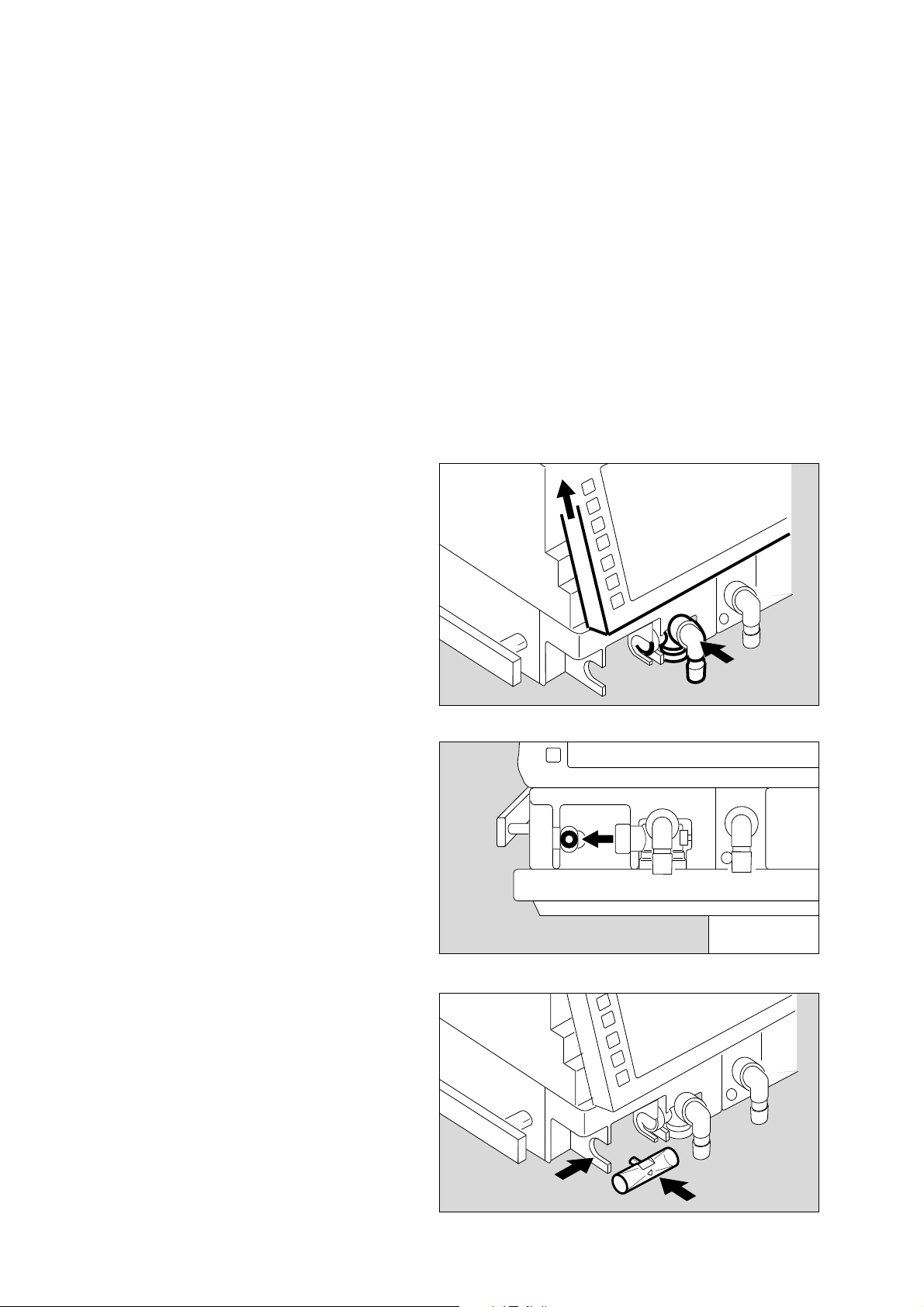
Attaching components
● Always use properly prepared parts, see Preparing,
page 135.
Fitting the expiration valve
● Tilt the control unit upwards.
● Push the expiration valve as far as it will go into the
mounting. Check that it is properly engaged by gently
pulling the port.
Fitting the flow sensor
1 Push socket to left as far as it will go.
1
2 Fit flow sensor – with the probe facing towards the
ventilator – into the mounting and push it into the
socket as far as it will go.
Then:
3 Push flow sensor to the right as far as it will go into
the rubber lip of the expiration valve.
30
3
2
Page 31

Fitting O2 sensor capsule
– when using the system for the first time
– when the display reads:
O2 measurement inop
– when calibration can no longer be performed.
● Tilt control unit upwards.
1 Turn port downwards or to the left.
2 Use coin to loosen screw, and remove protective
cover.
3 Loosen the two knurled screws and open the sensor
housing.
4 Insert new sensor capsule.
The sensor end with the circular tracks on the
contacts goes into the housing.
Preparation
Attaching components
Heat and Moisture Exchangers
1
2
3
3
● Close the sensor housing securely with the two
knurled screws.
● Screw protective cover back in place.
● Dispose of the used sensor, please refer to
page 144.
Note on the Use of Heat and
Moisture Exchangers
The use of a heat and moisture exchanger (HME) in the
patient connection can increase breathing resistance
considerably.
An increase in breathing resistance will lead to greater
effort in spontaneous breathing and greater trigger effort
during assisted ventilation. Under unfavourable
conditions, an increase in breathing resistance can lead
to an inadvertent PEEP.
This breathing resistance in the patient hose system
cannot be monitored by the ventilator.
4
3
● Therefore you should regularly check the condition of
the patient and the ventilator's measured values for
volume and resistance.
● Follow the Instructions for Use of the heat and
moisture exchanger (HME).
● Do not use the heat and moisture exchanger (HME)
at the same time as a medicament nebuliser or
humidifier!
31
Page 32

Preparation
Ventilation Adults and Children
Ventilation Adults and Children
From 100 mL tidal volume VT upwards
Patient mode: »Adults«
Do not use a heat and moisture exchanger at the
same time as a humidifier!
Risk of increased breathing resistance due to
condensation.
Connecting Aquapor humidifier
Prepare Aquapor following the relevant Instructions for
Use.
1 Hang Aquapor from rail by bracket and tighten
screws.
2 Insert elbow connector into Aquapor.
3 Insert the double connector into the elbow connector.
● Fill Aquapor bowl to the upper mark with distilled
water.
Connecting ventilation hoses
Do not use antistatic or conductive hoses*.
Depending on the desired position of the ventilator in
relation to the bed, the hinged arm can be fitted to either
side of the machine.
Attachment on left-hand side:
3
2
1
D Evita 4
4 Turn both ports to the left.
5 Turn Aquapor to the left.
The following description applies when the ventilation
hoses have been attached on the left-hand side.
______________
* DIN VDE 0750 Part 215:
The use of anti-static or electrically conductive material in the
breathing system of the lung ventilator is not considered conducive
to greater safety. On the contrary, the use of these materials
increases the danger of electric shock to the patient and of fire due
to the presence of oxygen.
32
4
5
Page 33

1 Hang the hinged arm from the rail on the left-hand
side and tighten screws.
● Connect ventilation hoses, and note length of hose
(metres).
2 Turn ports in direction of hoses.
3 Install water traps in vertical position.
● Connect the Y-piece, with the rubber sleeve of the
Y-piece on the inspiratory side.
0,6m
0,6m
Preparation
Ventilation Adults and Children
D
1
0,4m
2
Fitting temperature sensor
4 Push sensor as far as it will go into the rubber sleeve
on the inspiratory side of the Y-piece. Align the
Y-piece so that the sensor is at the top.
5 Attach the sensor cable with hose clips.
6 Insert the probe of the temperature sensor into the
socket »Temp m« at the rear of the unit.
0,6m
0,4m
3
4
5
6
33
Page 34

Preparation
Ventilation Adults and Children
Ventilating Infants
Fitting CO2 cuvette and CO2 sensor
(optional)
1 Fit the cuvette to the patient connection of the
Y-piece, with the cuvette windows facing the side.
2 Push the CO2 sensor on to the cuvette, with the cable
trailing towards the unit.
● Insert the probe of the CO2 sensor in the socket
»CO2 m« on the rear panel of the Evita 4.
2
1
Ventilating Infants
Up to 300 mL tidal volume VT
Patient mode »Paediatrics«
Do not use a heat and moisture exchanger at the
same time as a humidifier!
Risk of increased breathing resistance because of
condensation.
Fitting bacterial filter
● Fit the bacterial filter to the inspiratory port.
34
D Evita 4
Page 35

Fitting humidifier and ventilation hoses
● Prepare the "Fisher & Paykel MR 730" breathing
gas humidifier as specified in the Instructions for Use
of the humidifier.
Use the relevant hose set K (paediatric).
● Clamp the humidifier to the stand under the apparatus
and screw firmly into place.
● Clamp the articulated arm to the left-hand rail and
screw firmly into place.
● Fit the ventilation hoses.
Check the hose lengths (metres).
● Fit the water trap in the vertical position.
Preparation
Ventilating Infants
If using bacterial filters
D Evita 4
0,4m
1,1m
0,6m
0,6m
Do not place any liquid containers above or on top
of Evita 4!
Any leaking or spilled liquid could cause
malfunctions!
If using bacterial filters
The use of expiratory bacterial filters on the ventilator is
not recommended.
However, if bacterial filters are nevertheless used on the
expiration side, an undesirable increase in breathing
resistance is possible.
Especially during medicament nebulisation and
humidifying, the resistance of the bacterial filter may
increase gradually. For the patient, the effect may be
increased breathing effort and intrinsic PEEP.
An intrinsic PEEP can be recognised by the fact that the
expiratory flow does not return to "0" before the end of
expiration.
If PEEP is unacceptably high, the unit signals the
»PEEP high« alarm.
● Check the bacterial filter and replace it if it is the
cause of the PEEP.
35
Page 36

Preparation
Supply and Connections
Supply and Connections
Electrical power supply
The ventilator is designed for a mains voltage of:
either : 220 V to 240 V
or : 100 V to 127 V
● Insert the plug in the mains socket.
For operation with DC power unit and external battery
(option)
either : 12 V
or : 24 V
● Connect the external battery by cable.
Note on the use of a socket strip for ancillary
equipment
Connecting other devices to the same extension socket
strip may, in the event of earth failure, cause the current
leakage to the patient to increase beyond the permissible
values.
In this case, the risk of electric shock cannot be
eliminated.
Temporary interruption of power supply
e.g. if hospital reserve power supply is activated.
Without the 12/24 V DC power unit:
During a power interruption, Evita 4 outputs a continuous
alarm tone for max. 2 minutes.
The duration of this alarm tone may be shorter if Evita 4
was switched on for less than 15 minutes.
Evita 4 tolerates power interruptions shorter than 10 milliseconds – without any effect on ventilation.
In the case of power interrupts lasting longer then
10 milliseconds, the machine restarts with a short selftest lasting about 4 seconds – ventilation is continued
with the same values that were set before the power
interruption.
If a lower alarm limit has been set for the minute volume,
the MV low alarm is activated until the measured value
has risen above the lower alarm limit.
With 12/24 V DC power unit (option):
Follow Instructions for Use of Evita 4 DC option
(DC power supply).
36
Page 37

Gas supply
● Screw the connecting hoses for medical air and
oxygen to the back panel of Evita 4 and insert their
probes into the terminal units.
The compressed gases must be dry and free from
dust and oil. Gas pressure must be 3 to 6 bar.
Preparation
Supply and Connections
Air O2
37
Page 38

Preparation
Evita Remote
Evita Remote
Optional remote control unit (Remote Pad)
The kit may only be installed and programmed by
specialists.
For parallel, remote operation of the following LED and
key functions:
1 Red LED – to indicate warning messages
2 Yellow LED – to indicate caution and advisory
messages
3 »gggg« key – to suppress the alarm tone for approx.
2 minutes
1
2
3
4 »Alarm Reset« key – to acknowledge alarm messages
5 » Neb.« key – to start and end medicament
nebulisation
6 »O2 suction« key – for bronchial suctioning
7 »Insp. hold« key – for sustained, manually induced
inspiration
8 »Exp. hold« key – for extended and sustained
expiration
The function of the respective LEDs and keys is the same
as that of the corresponding elements on the front panel
of Evita 4 and is described in the application chapters of
the Instructions for Use.
Connection
● Plug the lead of the Remote Pad into the socket » «
on the rear of Evita 4. The plug can be connected or
disconnected at any time without impairing operation
of Evita 4.
4
5
6
7
8
38
Page 39

● Hook holder onto a standard rail and clamp into place.
● Hang Remote Pad into holder from above.
Preparation
Remote Pad
Note automatic self-test
– when connecting the Remote Pad to Evita 4 while the
latter is switched on
or
– when switching on Evita 4 after connecting the
Remote Pad.
● Do not press any keys on the Remote Pad.
● All LEDs on the Remote Pad light up for 5 seconds:
– Red LED
– Yellow LED
– Yellow LEDs in the keys
● The Remote Pad is tested by Evita 4. An advisory
message is output if a fault is detected, see page 127
"Troubleshooting".
39
Page 40

Preparation
Nurse call (optional)
Nurse call
(optional)
Socket on the rear of Evita 4 for connecting alarm signals
to a central alarm station in the hospital.
● The kit may only be installed by specialists.
● The 6-pin round DIN plug (female connector) must be
connected to the lead for the central alarm station in
the hospital by a specialist.
5
3
Connection 3-5 makes and the nurse call is activated as
soon as Evita 4 signals an alarm.
● Plug the connector into the » « socket on the rear
and screw into place.
● Check correct operation of connected nurse call
system.
Only alarm messages of the highest priority
(see page 78) are transmitted via nurse call.
Warning messages are displayed in the top line of the
screen in red and with three exclamation marks, see
page 78. Caution and advisory messages are not
transmitted. The nurse call is also activated when the
internal loudspeaker in the ventilator is defective.
Connection of a nurse call does not relieve staff of
their duty to check the monitoring on the Evita 4
screen at regular intervals.
● Screen displays must be checked regularly.
1
1 5
3
A fault in any of the components in the link between
nurse call and central hospital alarm system (e.g. in
the electronics for nurse call in Evita, in the Evita
power supply, or in the alarm generator of the central
hospital alarm system) may result in failure of the
nurse call.
Background: The hospital connections to the central
alarm typically use only one channel. The electronics for
nurse call consequently also uses only one channel.
Technical Data
Floating DC contact
Input voltage Max. 40 V =
Input current Max. 500 mA
Switching capacity Max. 15 W
40
Page 41

Before Using for the First Time
Setting the language of the screen texts
Evita 4 leaves the factory programmed with German
screen texts.
The following alternative languages can be selected:
– English
– French
– Italian
– Spanish
– Dutch
– Swedish
– American English
– Japanese
– Greek
– Russian
– Portuguese
– Arabic
– Chinese
– Turkish
Preparation
Before Using for the First Time
● Switch on machine = press power switch on the back
panel until it clicks into position.
The flap falls over the button to protect against
inadvertent switching off (to switch off, pivot the flap
upwards and press the button in fully).
Evita 4 runs through its self-test procedure,
● Wait until the 10-second test phase is complete.
After the self-test:
1 Switch Evita 4 to Standby = hold down key »O «
for about 3 seconds.
2 Switch off the standby alarm tone with the »Alarm
Reset« key.
3 Press the »Configuration« key.
● Touch the »System Defaults« screen key.
● Touch the »Language/Units« screen key.
● Touch the »Language« key.
● Select the desired language and confirm.
The selected language is now active.
D Evita 4
2
3
1
● Ask our specialists to change the labels on the control
unit keys.
049 37 207
41
Page 42

Preparation
Device Check
Device Check
Before use on patient
Immediately before using on the patient, check that the
machine is working properly and is ready for operation.
Evita 4 supports this »device check« by means of a builtin checklist that guides the user through the test in a
dialogue mode.
The following functions are performed during this device
check:
– Checking that the machine assembly is complete,
– Testing the alarm tone,
– Testing the expiratory valve,
– Testing the air-O2 change-over valve,
– Testing the safety valve,
– Calibrating the flow sensor,
– Calibrating the O2 sensor,
– Calibrating the CO2 sensor,
– Testing the leakproofing of the hose system,
– Checking the compliance of the hose system.
The test results obtained from this device check and the
calibration and zero-checking values of the sensors
remain stored until the next calibration – even if the
device is switched off.
If the hose system, type of humidification or patient mode
is changed after performing the device check, the
leakproofing test must be repeated before starting
operation.
Preparing the adult test lung 84 03 201
for the adult hose system
The test lung consists of an elbow connector for
connection to the Y-piece, a 7 mm diameter catheter
connection for simulating the resistance of the airways
and a 2 litre breathing bag to simulate compliance.
● Overextended breathing bags must not be used as
they may cause artefacts during the device check!
● The elbow connector must not be plugged into the
patient connection of the Y-piece until directed by
Evita 4.
42
Page 43

Preparing the child test lung 84 09 742
for the paediatric hose set
The test lung consists of a tracheal tube CH 12 to
simulate the resistance of the airways and a small
bellows to simulate compliance.
● Only insert the elbow connector into the Y-piece
when Evita 4 advises you to do so on the screen.
Preparation
Device Check
Performing the device check
● Switch on the machine = press power switch on the
back panel until it clicks into position.
Evita 4 runs through its self-test procedure.
● Wait until the 10-second test phase has been
completed.
After the self-test:
1 Switch Evita 4 to standby = Hold down key »O «
for about 3 seconds.
2 Switch off the standby alarm tone with the
»Alarm Reset« key.
● Touch the »Device check« screen key.
D Evita 4
2
1
43
Page 44

Preparation
Device Check
Display:
Before starting the check, enter the type of humidifier
selected:
– Active humidifier, e.g. Dräger Aquapor
or
– HME/Filter (artificial nose)
If the type of humidifier is known, Evita 4 can take the
temperature and moisture situation into account when
measuring the volume parameters.
● Touch the »Humid.« screen key.
054 37 207
Display:
● Touch the »Active Humid.« screen key
or
● Touch the »HME/Filter« screen key.
● Confirm selection = press rotary knob.
The selected type of humidifier is indicated by a yellow
LED.
The humidifier selection is saved and remains effective
even when the equipment is switched on again.
If the type of humidifier is changed and has to be
reselected on the screen, the following test steps are
shown to be invalid (– –) after the device check:
– Humidification
– Air tight check
The operator is prompted to repeat the device check for
these two steps.
055 37 207
Start the check procedure:
● Press the »Check« screen key.
Evita 4 starts running through the dialogue-oriented
check.
The check procedure is semi-automatic.
During the device check, the user is instructed by Evita 4
to perform specific actions on the device.
44
Page 45

The following tests are performed during the device
check:
– Correct operation of auxiliary and power failure alarms
– Seating and clear passage of the expiratory valve
– Seating of the flow sensor
– Seating of the neonate flow sensor
(if "NeoFlow" option is installed)
– Type of humidifier
– Completeness of hose system
– Function of the air-O2 changeover valve
– Function of the safety valve
– Gas supply
Preparation
Device Check
– Calibration of the flow sensor
– Calibration of the neonate flow sensor
(if "NeoFlow" option is installed)
– Calibration of the O2 sensor
– Leakproofing of the hose system
On completion of the device check, a checklist is
displayed on the screen to show the results of the check.
Correct result : ✓
Incorrect result : F
Check not performed : – –
In the event of incorrect results, e.g. if the hose system is
not sufficiently leakproof:
● Eliminate the cause of the fault
● Touch the »Repeat check« screen key
Only the tests with incorrect results are repeated.
After successful completion of the device check,
Evita 4 is ready for operation.
Either:
● immediately start up Evita 4 by pressing key »O «
or:
● leave Evita in standby mode
or:
● switch off Evita for later use.
Switch on back panel = pivot flap to the side and
press button in fully and release.
D Evita 4
45
Page 46

Preparation
Device Check
Checking the hose system for leaks
The hose system is tested for leaks during the device
check but must also be monitored independently of the
device check, e.g. after changing the hose system.
● Touch the »Air tight check« screen key.
During the test, the current leakage flow is continuously
displayed.
A leakage flow of 300 mL/min at a pressure of 60 mbar
is permitted.
After the leak test, the Evita 4 unit determines the
compliance and resistance of the hose system.
The calculated compliance of the hose system is used by
Evita 4 for automatically correcting the volume controlled
ventilation strokes and the measured values of the flow
monitoring system, see page 170.
057 37 207
The calculated resistance of the hose system is used by
Evita 4 to correct the pressure measurement in the
presence of a basic flow (NeoFlow option).
When changing the patient mode or type of humidifier,
the device automatically sets the hose compliance and
resistance to the default values.
By checking the system for leaks, the device determines
the momentary compliance and resistance.
Therefore:
When changing the patient mode, hose system or
type of humidifier:
● Always perform the leak test.
46
Page 47

Positioning the control unit
● Do not lean the control unit.
When changing, lay it on its back.
To position the control unit on the wall rail
1 Hold down the segments on the right and left, and tilt
the control unit fully downwards.
2 Hold down the release buttons on the left and right,
and remove the control unit from the Evita 4 mounting.
● Uncoil the cable as far as necessary.
● Clip the control unit to the wall rail and
3 lock in place = pull down the latch situated beneath
the bracket and turn it in the direction of the wall rail.
Preparation
Positioning the control unit
1
1
1 Hold down the segments on the right and left and at
the same time tilt the control unit to the desired
position.
2
2
3
To position the control unit on the device
● Hold down the segments on the right and left and tilt
the control unit fully downwards.
● Release the control unit = turn the latch away from the
wall rail and lift the control unit off the rail.
● Coil the cable.
● Hang the control unit in the Evita 4 mounting so that it
rests in position.
● Hold down the segments on the right and left, and at
the same time tilt the control unit to the optimal
position.
47
Page 48

48
Page 49

Operation
Contents
Operation
Contents
Starting up................................................................50
Switching on..............................................................50
Patient mode............................................................ 50
Selecting the patient mode.........................................51
Entering the ideal body weight................................... 51
Select the previous settings....................................... 51
Starting ventilation..................................................... 52
Setting Ventilation Modes........................................ 53
IPPV..........................................................................53
SIMV, SIMV/ASB...................................................... 57
BIPAP, BIPAP/ASB...................................................60
BIPAPAssist................................................................62
CPAP, CPAP/ASB....................................................63
MMV, MMV/ASB.......................................................65
APRV........................................................................ 67
Independent Lung Ventilation ILV............................ 69
Preparation................................................................69
Setting the master and slave device........................... 71
Apnoea ventilation....................................................76
Selecting/Quitting Standby Mode............................96
Calibration................................................................ 97
Calibrating O2 sensor................................................ 97
Calibrating flow sensor.............................................. 98
External flow source...................................................99
Checking/calibrating CO2 sensor............................ 100
CO2 zero checking..................................................100
Testing CO2 calibration with test filter......................102
Testing CO2 calibration with test gas.......................103
Calibrating CO2 sensor........................................... 105
Resetting CO2 calibration........................................106
Setting Alarm Limits.................................................77
In the Event of an Alarm...........................................78
Cancel alarm tone......................................................79
Information J............................................................ 79
Displaying Curves and Measured Values.................80
Displaying measured values....................................... 81
Trends.......................................................................82
Loops........................................................................83
Reference curve displays........................................... 83
Single stroke displays................................................ 83
Zoom loops (optional)................................................ 83
Display loops in the upper graphic area......................84
Logbook.................................................................... 85
Screen freeze............................................................ 86
Special Functions.....................................................87
Manual inspiration......................................................87
Exspiration Hold.........................................................87
Medicament nebulisation............................................88
Oxygen enrichment for bronchial suction....................91
Special measurement procedure: intrinsic PEEP........ 93
Special measurement procedure: occlusion
pressure P 0.1...........................................................94
Shut-down.................................................................95
49
Page 50

Operation
Starting up
Starting up
Switching on
● Push in power switch on back panel until it clicks into
place = ON.
The flap comes down over the switch to prevent it
being inadvertently switched off.
Evita 4 runs a self-test.
● Wait until the 10-second test phase is complete.
Evita 4 always begins ventilation with the start-up values
marked by an arrow on the on-screen knobs.
To select these start-up values, please refer to
pages 119 et seq..
After power cuts and after standby mode, the settings
valid immediately before the interruption of operation
remain in use.
Patient mode
After switching on, Evita 4 displays a choice of patient
modes:
–»Adults« = adult patients
–»Paed.« = children
–»Neo.« = neonates
(when using the "NeoFlow" option)
–»prev. patient« = previous patient
The device also asks the user to enter the weight of the
patient (ideal body weight).
Example:
Adult ventilation
With this information, Evita 4 defines the adjustment
ranges and the start-up values of the ventilation
parameters.
The starting procedure, with selection of the patient
mode, can be configured by the user, see Configuration
on page 107 onwards.
50
062 37 207
Page 51

The screen key »prev. patient« can be used to restore
the specific patient settings, including alarm limits and
monitoring status, effective before switching off the
device.
Example:
Previous patient
The previous modes are displayed in the status line:
– Previous ventilation mode
– Previous patient mode
– Previous application mode (tube or mask for
optional NIV)
Operation
Starting up
063 37 207
The key »prev. patient« is not displayed by Evita 4
following a loss of data or removal of a previously used
option (e.g. NeoFlow), thus preventing restoration of the
previous setting.
Restoration of the previous setting is similarly prevented
by Evita 4 if it was configured in such a way before
switching off that the former patient mode is no longer
available.
Selecting the patient mode
if configured
EITHER
● the »Adults« key or
the »Paed.« key or
the »Neo.« key (NeoFlow option) and
enter the ideal body weight
if configured
With the ideal body weight, Evita 4 determines the
start-up settings of the ventilation parameters. The
start-up value is marked on the relevant screen knob
by an arrow ( j).
● Touch the screen knob.
● Enter the ideal body weight [kg] with the manual
dial-knob = turn rotary knob.
● Confirm the setting = press rotary knob.
OR
Select the previous settings
● Touch the key »prev. patient«.
● Confirm = press rotary knob.
062 37 207
51
Page 52

Operation
Starting up
Starting ventilation
● Press the rotary knob again.
Evita 4 starts ventilation with the ventilation mode
configured by the user.
The machine is factory-set to IPPV.
Evita 4 displays the »Settings« screen page.
The user can check and correct the settings on the
screen.
065 37 207
52
Page 53

Setting Ventilation Modes
The ventilation modes IPPV, BIPAP, SIMV and ASB are
already configured in the unit. If other ventilation modes
are used, please refer to page 113 "Selecting ventilation
modes".
IPPV
Intermittent Positive Pressure Ventilation
Volume-controlled ventilation with fixed, mandatory
minute volume MV and user-adjusted tidal volume VT
and frequency f.
For patients having no spontaneous breathing.
Paw
Insp.
pause
Pplat
Operation
Setting Ventilation Modes
Pmax
(configurable)
PEEP
Set the pattern of ventilation for IPPV with the ventilation
parameters:
Tidal volume »VT«
Insp. Flow »Flow«
Frequency »f«
Inspiration time »Tinsp«
O2 concentration »O2«
Positive end-expiratory pressure »PEEP«
––––––––––––––––––––––––––––––––––––––––––––––––
To set:
● Touch the relevant screen knob.
● Adjust value = turn rotary knob.
● Confirm setting = push rotary knob.
––––––––––––––––––––––––––––––––––––––––––––––––
Flow
insp Te
T
1
f
Insp. flow
t
t
53
065 37 207
Page 54

Operation
Setting Ventilation Modes
IPPV can be expanded by the following ventilation
parameters:
Flowtrigger (IPPV Assist) – for synchronisation with
attempted spontaneous breathing by the patient.
By switching on the flow trigger and setting the trigger
level, the mandatory strokes are synchronised with the
patient's spontaneous breathing attempts.
Spontaneous breathing activity by the patient is indicated
by the brief display of a lung symbol instead of the usual
symbol for the patient mode.
068 37 207
Sigh – for prophylactic treatment of atelectasis.
Atelectasis can be prevented by switching on the Sigh
function and setting the sigh in the form of an intermittent
PEEP.
When the Sigh function is activated, the end-expiratory
pressure increases for two ventilation strokes every
3 minutes by the set value of the intermittent PEEP.
AutoFlow – for automatic regulation of the inspiration
flow.
With AutoFlow *, the inspiration flow is decelerated and
regulated, so that at the selected tidal volume VT with the
current lung compliance a minimum airway pressure is
reached and pressure peaks are avoided.
Evita 4 delivers additional inspiration flow if and when the
patient breathes in – limited by the alarm limit VTi >
The patient can also breathe out during the inspiratory
plateau phase.
The inspiratory pressure is limited by the Paw > alarm
limit.
069 37 207
● Set the alarm limits MV < and MV > in order to
avoid excessive or insufficient flow following rapid
changes in compliance.
––––––––––––
* Please refer to page 160 for a detailed description of AutoFlow
and PLV.
54
Page 55

––––––––––––––––––––––––––––––––––––––––––––––––
To set:
● Touch the »Extra settings« screen key.
● Touch the screen key corresponding to the desired
function.
For Flow Trigger and Sigh:
● Touch the appropriate screen key.
● Adjust the desired value = turn the rotary knob
● Confirm the desired setting = press the rotary knob
● Switch on the function = touch the »On« screen
button and press the rotary knob.
Operation
Setting Ventilation Modes
––––––––––––––––––––––––––––––––––––––––––––––––
IPPV can be configured for the additional ventilation
parameter Pmax.
Selecting »Pmax pressure limiting«, see page 115.
Pressure Limited Ventilation (PLV)* – for manually
limiting pressure peaks using the Pmax pressure limit.
The tidal volume remains constant as long as the pressure curve shows a plateau and the inspiratory flow curve
shows a brief flow pause between inspiration and
expiration.
● To set the "Pmax" pressure limit, please refer to
page 115.
The value of Pmax is displayed as a dashed blue line in
the Paw (t) curve.
The "Inconstant volume" alarm is always active. It is
triggered automatically if the tidal volume VT can no
longer be applied.
This visual and audible alarm can be suppressed with
the »Alarm Reset« key until the cause of the alarm is
remedied.
070 37 207071 37 207
––––––––––––
* Please refer to page 160 for a detailed description of AutoFlow
and PLV.
55
Page 56

56
Page 57

SIMV, SIMV/ASB
Synchronized Intermittent Mandatory Ventilation*
Assisted Spontaneous Breathing**
Fixed mandatory minute volume MV set with tidal volume
VT and frequency f. Between the mandatory ventilation
strokes, the patient can breathe spontaneously, thereby
contributing to the minute volume. Spontaneous
breathing can be supported by ASB.
Paw
PEEP
Pmax
(configurable)
Operation
Setting Ventilation Modes
ASB pressure
assist
fast
rise time
slow
rise time
For patients with insufficient spontaneous breathing or for
patients who are being weaned by progressive reduction
of the mandatory proportion of the total minute volume.
The frequency can be reduced to 0 during the weaning
process. The device automatically changes to the
ventilation mode CPAP or CPAP/ASB. This ventilation
mode is also indicated on the screen.
The screen key »SIMV« and the screen knobs for setting
the SIMV parameters remain on display.
Set the pattern of ventilation for SIMV and SIMV/ASB
with the ventilation parameters:
Tidal volume »VT«
Insp. flow »Flow«
Frequency »f«
Inspiration time »Tinsp«
O2-concentration »O2«
Positive end-expiratory pressure »PEEP«
Pressure support »PASB«
Pressure rise time » «
––––––––––––––––––––––––––––––––––––––––––––––––
To set:
Flow
T
insp
1
f
Insp. Flow
Trigger window
t
t
● Touch the appropriate screen knob.
● Adjust to the desired value = turn rotary knob.
● Confirm setting = press the rotary knob.
––––––––––––––––––––––––––––––––––––––––––––––––
SIMV and SIMV/ASB can be expanded with the following
ventilation parameters:
Flowtrigger – for synchronisation with attempted
spontaneous breathing by the patient.
By setting on the flow trigger level, the mandatory strokes
are synchronised with the patient's spontaneous
breathing attempts.
Spontaneous breathing activity by the patient is indicated
by the brief display of a lung symbol instead of the usual
symbol for the patient mode.
_____________
* Please refer to page 164 for a detailed description of SIMV.
** Please refer to page 165 for a detailed description of ASB.
073 37 207
57
Page 58

Operation
Setting Ventilation Modes
Apnoea Ventilation – for automatic switch-over to
volume-controlled mandatory ventilation if the patient
stops breathing.
If breathing stops, Evita 4 emits an alarm after the set
alarm time (TApnoea > ) and starts volume-controlled
ventilation with the set ventilation parameters:
Frequency »f Apnoea«
Tidal volume »VTApnoea«
AutoFlow – for automatic optimisation of the inspiration
flow.
With AutoFlow*, the inspiration flow is decelerated and
regulated, so that at the selected tidal volume VT with the
current lung compliance a minimum airway pressure is
reached and pressure peaks are avoided.
Evita 4 delivers additional inspiration flow when the
patient breathes in – limited by the alarm limit VTi >
The patient can also breathe out during the inspiratory
plateau phase.
The inspiratory pressure is limited by the Paw > alarm
limit.
● Set the alarm limits MV < and MV > in order to
avoid excessive or insufficient flow following rapid
changes in compliance.
Spontaneous breathing
Paw
with ASB pressure support
rapid
rise time
Flow
slow
rise time
apnoea alarm time
T
Apnoea >
Start of apnoea
ventilation
PEEP
t
t
––––––––––––––––––––––––––––––––––––––––––––––––
To set (Example: Apnoea Ventilation)
● Touch the »Extra settings« screen key.
● Touch the screen key corresponding to the desired
function , e.g. »Apnoe Vent.«.
● Switch on the function = touch the »On« screen knob
and press in the rotary knob.
● Set values = touch the corresponding screen knob,
turn and press rotary knob.
––––––––––––––––––––––––––––––––––––––––––––––––
SIMV and SIMV/ASB can be configured with the
additional ventilation parameter Pmax.
Select »Pmax pressure limiting«, see page 115.
075 37 207
58
Page 59

Pressure Limited Ventilation (PLV)* – for manually
limiting pressure peaks using the Pmax pressure limit.
The tidal volume remains constant as long as the
pressure curve shows a plateau and the inspiratory flow
curve shows a brief flow pause between inspiration and
expiration.
● To set the "Pmax" pressure limit, please refer to
page 115.
The value of Pmax is displayed as a dashed blue line in
the Paw (t) curve.
The "Inconstant volume" alarm is always active. It is
triggered automatically if the tidal volume VT can no
longer be applied.
This visual and audible alarm can be suppressed with the
»Alarm Reset« key until the cause of the alarm is
remedied.
Operation
Setting Ventilation Modes
076 37 207
––––––––––––
* Please refer to page 160 for a detailed description of AutoFlow
and PLV.
59
Page 60

Operation
Setting Ventilation Modes
BIPAP, BIPAP/ASB
Biphasic Intermittent Positive Airway Pressure
Assisted Spontaneous Breathing
Pressure-controlled ventilation combined with free
spontaneous breathing during the complete breathing
cycle, and adjustable pressure support at CPAP level.
The mandatory proportion of the total minute volume MV
is set with inspiratory pressure Pinsp above PEEP and
Frequency f.
For a range of patients, from those unable to breathe
spontaneously to those breathing spontaneously before
extubation. Patients are weaned off the ventilator by
progressive reduction of the mandatory proportion of the
overall minute volume MV and reduction of the pressure
support PASB.
PEEP
Paw
Flow
fast
rise time
Tinsp
slow
rise time
Pinsp
Trigger window for
insp. and exp. synchronisation
1
f
ASB
pressure assist
fast
rise time
slow
rise time
t
t
The frequency can be reduced to 0 during the weaning
process. The device automatically changes to the
ventilation mode CPAP or CPAP/ASB. This ventilation
mode is also indicated on the screen.
The screen key »BIPAP« and the screen knobs for setting
the BIPAP parameters remain on display.
Set the pattern of ventilation for BIPAP and BIPAP/ASB
with the ventilation parameters:
Inspiration pressure »Pinsp«
Frequency »f«
Time »Tinsp«
O2 concentration »O2«
Positive end-expiratory pressure »PEEP«
Pressure support »PASB«
Pressure rise time » «
The inspiration pressure »Pinsp« can be reduced to the
PEEP level, in which case the ventilation pattern
corresponds to CPAP or CPAP/ASB.
The inspiration pressure »Pinsp« is set as an absolute
value. Pressure support »PASB« is set relative to the
PEEP level.
without
spontaneous breathing
with
spontaneous breathing
––––––––––––––––––––––––––––––––––––––––––––––––
To set:
● Touch the appropriate screen knob.
● Adjust to the desired value = turn rotary knob.
● Confirm setting = press the rotary knob.
––––––––––––––––––––––––––––––––––––––––––––––––
60
078 37 207
Page 61

BIPAP and BIPAP/ASB can be expanded with the
following ventilation parameters:
Flowtrigger – for synchronisation with attempted
spontaneous breathing by the patient.
By setting on the flow trigger level, the mandatory strokes
are synchronised with the patient's spontaneous
breathing attempts.
Spontaneous breathing activity by the patient is indicated
by the brief display of a lung symbol instead of the usual
symbol for the patient mode.
Apnoea Ventilation – for automatic switch-over to
volume-controlled mandatory ventilation if the patient
stops breathing.
If breathing stops, Evita 4 emits an alarm after the set
alarm time (TApnoea > ) and starts volume-controlled
ventilation with the set ventilation parameters:
Frequency »fApnoea«
Tidal volume »VTApnoea«
Operation
Setting Ventilation Modes
––––––––––––––––––––––––––––––––––––––––––––––––
To set (Example: Flowtrigger)
● Touch the »Extra settings« screen key.
● Touch the screen key corresponding to
»Flowtrigger«.
● Set values = touch the »FlowTrig« screen knob, and
turn and press the rotary knob.
––––––––––––––––––––––––––––––––––––––––––––––––
079 37 207
61
Page 62

Operation
Setting Ventilation Modes
BIPAPAssist
Biphasic Positive Airway Pressure Assisted
pressure-controlled, assisted ventilation
The inspiratory strokes are the same as for BIPAP, but
the changeover from Pinsp to PEEP is not synchronised
with expiration by the patient.
The patient can breathe spontaneously at PEEP level
through the entire ventilation process.
Every spontaneous breathing activity by the patient
triggers a synchronised inspiratory stroke.
A non-synchronised inspiratory stroke is started by the
device at the latest upon expiry of the time »f«.
For all patients, from those unable to breathe
spontaneously to those breathing spontaneously before
being weaned off the ventilator.
Set ventilation pattern for BIPAPAssist with the following
parameters:
Inspiratory pressure »Pinsp«
Frequency »f«
Inspiration time »Tinsp«
PEEP
Paw
fast
rise time
Tinsp
Flow
spontaneous breathing
without
slow
rise time
Pinsp
Trigger window
1
f
for synchronisation
with
spontaneous breathing
t
t
O2 concentration »O2«
Positive end-expiratory pressure »PEEP«
Pressure rise time » «
Flow trigger »FlowTrig«
The inspiratory pressure »Pinsp« is set as an absolute
value.
––––––––––––––––––––––––––––––––––––––––––––––––
To set:
● Touch the appropriate screen knob.
● Adjust to the desired value = turn rotary knob.
● Confirm setting = press the rotary knob.
––––––––––––––––––––––––––––––––––––––––––––––––
62
081 37 207
Page 63

CPAP, CPAP/ASB
Continuous Positive Airway Pressure
Assisted Spontaneous Breathing
Operation
Setting Ventilation Modes
Spontaneous breathing at a raised pressure level in order
to increase the functional residual capacity (FRC).
Spontaneous breathing can be assisted with additional
pressure by ASB.
For patients breathing spontaneously.
Set the pattern of ventilation for CPAP and CPAP/ASB
with the following ventilation parameters:
O2 concentration »O2«
Positive end-expiratory pressure »PEEP«
Pressure support »PASB«
Pressure rise time » «
––––––––––––––––––––––––––––––––––––––––––––––––
To set:
● Touch the appropriate screen knob.
● Adjust to the desired value = turn rotary knob.
● Confirm setting = press the rotary knob.
––––––––––––––––––––––––––––––––––––––––––––––––
Spontaneous breathing
Paw
with ASB pressure support
rapid
rise time
Flow
slow
rise time
apnoea alarm time
T
Apnoea >
Start of apnoea
ventilation
PEEP
t
t
CPAP and CPAP/ASB can be expanded with the
following ventilation parameters:
Flowtrigger – for synchronisation with attempted
spontaneous breathing by the patient.
By setting the trigger level, the mandatory ventilation
strokes are synchronised with the patient's spontaneous
breathing attempts.
Spontaneous breathing activity by the patient is indicated
by the brief display of a lung symbol instead of the usual
symbol for the patient mode.
Apnoea Ventilation – for automatic switch-over to
volume-controlled mandatory ventilation if the patient
stops breathing.
If breathing stops, Evita 4 emits an alarm after the set
alarm time (TApnoea > ) and starts volume-controlled
ventilation with the set ventilation parameters.
Frequency »fApnoea«
Tidal volume »VTApnoea«
083 37 207
63
Page 64

Operation
Setting Ventilation Modes
––––––––––––––––––––––––––––––––––––––––––––––––
To set (Example: Flowtrigger)
● Touch the »Extra settings« screen key.
● Touch the »Flow trigger« screen key.
● Set the value = touch the »FlowTrig« screen knob,
and turn and press the rotary knob.
––––––––––––––––––––––––––––––––––––––––––––––––
084 37 207
64
Page 65

MMV, MMV/ASB
Mandatory Minute Volume Ventilation
Assisted Spontaneous Breathing
Operation
Setting Ventilation Modes
The overall minute volume is preset to a mandatory level,
which can be adjusted by means of the tidal volume VT
and frequency f.
The patient can breathe spontaneously, thereby
contributing a portion of the overall minute volume.
The difference between the spontaneously breathed
minute volume and the set minute volume is covered by
the mandatory ventilation strokes. Spontaneous breathing
can be assisted by ASB pressure support.
This mode is intended for patients being weaned off the
ventilator by progressively reducing the mandatory
proportion of the overall minute volume.
Set the pattern of ventilation for MMV and MMV/ASB
with the ventilation parameters:
Tidal volume »VT«
Insp. flow »Flow«
Frequency »f«
Inspiration time »Tinsp«
O2 concentration »O2«
Positive end-expiratory pressure »PEEP«
Paw
Flow
MV
set
MV
PEEP
insp
T
1
f
T
V
Insp. Flow
mandatory MV
no spontaneous
breathing
Pmax
(configurable)
beginning spontaneous
breathing
ASB
pressure support
short
rise time
trigger phase
long
rise time
spontaneously
breathed MV
sufficient spontaneous
breathing
t
t
t
Pressure support »PASB«
Pressure rise time » «
––––––––––––––––––––––––––––––––––––––––––––––––
To set:
● Touch the appropriate screen knob.
● Adjust to the desired value = turn rotary knob.
● Confirm setting = press the rotary knob.
––––––––––––––––––––––––––––––––––––––––––––––––
MMV and MMV/ASB can be expanded with the following
ventilation parameters:
Flowtrigger – for synchronisation with attempted
spontaneous breathing by the patient.
By setting on the flow trigger level, the mandatory strokes
are synchronised with the patient's spontaneous
breathing attempts.
Spontaneous breathing activity by the patient is indicated
by the brief display of a lung symbol instead of the usual
symbol for the patient mode.
087 37 207
65
Page 66

Operation
Setting Ventilation Modes
AutoFlow – for automatic regulation of the inspiration
flow.
With AutoFlow*, the inspiration flow is decelerated and
regulated, so that at the selected tidal volume VT with the
current lung compliance a minimum airway pressure is
reached and pressure peaks are avoided.
Evita 4 delivers additional inspiration flow when the
patient breathes in – limited by the alarm limit VTi >
The patient can also breathe out during the inspiratory
plateau phase.
The inspiratory pressure is limited by the Paw > alarm
limit.
● Set the alarm limits MV < and MV > in order to
avoid excessive or insufficient flow following rapid
changes in compliance.
––––––––––––––––––––––––––––––––––––––––––––––––
To set (Example: Flowtrigger)
● Touch the »Extra settings« screen key.
● Touch the »Flowtrigger« screen key.
● Set value = touch the »FlowTrig« screen knob, and
turn and press the rotary knob.
––––––––––––––––––––––––––––––––––––––––––––––––
MMV and MMV/ASB can be configured with the
additional ventilation parameter Pmax.
Select »Pmax pressure limiting«, see page 115.
Pressure Limited Ventilation (PLV)* – for manually
limiting pressure peaks using the Pmax pressure limit.
The tidal volume remains constant as long as the pressure curve shows a plateau and the inspiratory flow curve
shows a brief flow pause between inspiration and
expiration.
● To set the "Pmax" pressure limit, please refer to
page 115.
088 37 207089 37 207
The value of Pmax is displayed as a dashed blue line in
the Paw (t) curve.
The "Inconstant volume" alarm is always active. It is
triggered automatically if the tidal volume VT can no
longer be applied.
This visual and audible alarm can be suppressed with the
»Alarm Reset« key until the cause of the alarm is
remedied.
––––––––––––
* Please refer to page 160 for a detailed description of AutoFlow
and PLV.
66
Page 67

APRV
Airway Pressure Release Ventilation
Operation
Setting Ventilation Modes
Free spontaneous breathing at a raised CPAP pressure
level together with a short period of low pressure
(Release).
This mode is intended for patients who are breathing
spontaneously but who need assistance with CO2
removal.
Set the pattern of ventilation for APRV with the ventilation
parameters:
Inspiration time »Thigh«
Expiration time »Tlow«
Inspiration pressure »Phigh«
Positive end-expiratory pressure »Plow«
O2-concentration »O2«
––––––––––––––––––––––––––––––––––––––––––––––––
To set:
● Touch the appropriate screen knob.
● Adjust to the desired value = turn rotary knob.
● Confirm setting = press the rotary knob.
Paw
Flow
Thigh
high
P
t
Plow
T
low
t
––––––––––––––––––––––––––––––––––––––––––––––––
APRV can be expanded with the following ventilation
parameters:
Apnoea Ventilation – for automatic switch-over to
volume-controlled mandatory ventilation if the patient
stops breathing.
If breathing stops, Evita 4 emits an alarm after the set
alarm time (TApnoea > ) and starts volume-controlled
ventilation with the set ventilation parameters:
Frequency »fApnoea«
Tidal volume: »VTApnoea«
091 37 207
67
Page 68

Operation
Setting Ventilation Modes
––––––––––––––––––––––––––––––––––––––––––––––––
To set (Example: Apnoea Ventilation)
● Touch the »Extra settings« screen key.
● Touch the »Apnoea vent.« screen key.
● Switch on the function = touch the »On« screen knob
and press in the rotary knob.
● Set values = touch the corresponding screen knob,
turn and press rotary knob.
––––––––––––––––––––––––––––––––––––––––––––––––
092 37 207
68
Page 69

ILV
Independent Lung Ventilation
Separate, differentiated, synchronised ventilation with
two Evita units, one for each lung. The two Evita units are
connected by analogue interfaces.
The two devices operate together in master/slave mode.
The master device controls the operation.
Preparation
The following device combinations are possible:
– Combination of two Evita 4 units
– Combination of Evita 4 and Evita 2 dura
Operation
Independent Lung Ventilation ILV
– Combination of Evita 4 and Evita 2
– Combination of Evita 4 and Evita.
Requirements for combinations
– Evita 2 or Evita units must be fitted with the EvitaBus
analogue interface (optional).
– Connecting cable 84 11 794 must be used to
connect Evita 4 to another Evita 4 or with an
Evita 2 dura.
– Connecting cable 84 11 794 must be used to
connect Evita 4 to an Evita 2 or Evita.
For Evita 4 – Evita 2 dura
and
Evita 4 – Evita 4:
● Connect the ILV ports of the two Evita units using
connecting cable 84 11 794.
69
Page 70

Operation
Independent Lung Ventilation ILV
For Evita 4 – Evita 2
and
Evita 4 – Evita:
● Connect the ILV port of the Evita 4 to the analogue
interface of the other Evita unit using connecting
cable 84 11 793.
0
0
0
70
Page 71

Setting the Master and Slave device
To perform independent lung ventilation:
● Set up one device for ILV/Master mode
and
● the other device for ILV/Slave mode.
● Set the desired parameters – see page 19.
● Do not activate ILV mode until all the parameters
for the ILV/Master and ILV/Slave are fully set.
Setting ILV/Master
Operation
Independent Lung Ventilation ILV
Volume-controlled ventilation with fixed, mandatory
minute volume MV, set with tidal volume VT and
frequency f.
For independent lung ventilation of patients with no
spontaneous breathing.
Set the ILV ventilation pattern with the parameters:
Tidal volume »VT«
Insp. flow »Flow«
Frequency »f«
Inspiration time »Tinsp«
O2 concentration »O2«
Positive end-expiratory pressure »PEEP«
––––––––––––––––––––––––––––––––––––––––––––––––
To set:
● Touch the appropriate screen knob.
● Adjust the desired value = turn rotary knob
● Confirm setting = press rotary knob.
Paw
Flow
Insp.
pause
Pplat
T
insp Te
1
f
Insp. flow
Pmax
(configurable)
PEEP
t
t
––––––––––––––––––––––––––––––––––––––––––––––––
ILV/Master can be supplemented by the following
ventilation parameters:
Flowtrigger (ILV/Master Assist) – for synchronisation
with attempted spontaneous breathing by the patient.
By switching on the flow trigger and setting the trigger
level, the mandatory strokes are synchronised with the
patient's spontaneous breathing attempts.
Spontaneous breathing activity by the patient is indicated
by the brief display of a lung symbol instead of the usual
symbol for the patient mode.
096 37 207
71
Page 72

Operation
Independent Lung Ventilation ILV
Sigh – for prophylactic treatment of atelectasis.
Atelectasis can be prevented by switching on the Sigh
function and setting the sigh in the form of an intermittent
PEEP.
When the Sigh function is activated, the end-expiratory
pressure is increased by the set value of the intermittent
PEEP for 2 ventilation strokes every 3 minutes.
ILV/Master can also be configured with the additional
ventilation parameter Pmax.
To set the »Pmax pressure limit«, please refer to
page 115.
Pressure Limited Ventilation (PLV) – for manually
limiting pressure peaks using the Pmax pressure limit.
The tidal volume remains constant as long as the
pressure curve shows a plateau and the flow curve
shows a brief flow pause between inspiration and
expiration.
● To set the »Pmax pressure limit«, please refer to
page 115.
The value of Pmax is displayed as a dashed blue line in
the Paw (t) curve.
The tidal volume is constantly monitored. If the tidal
volume VT can no longer be applied, the "Inconstant
volume" alarm is automatically triggered.
This visual and audible alarm can be suppressed with the
»Alarm Reset« key until the cause of the alarm is
remedied.
097 37 207
72
Page 73

Operation
Independent Lung Ventilation ILV
Setting ILV/Slave
Volume-controlled ventilation with fixed, mandatory
minute volume MV, set with the tidal volume VT and
frequency f of the ILV Master device and selectable Slave
mode.
For independent lung ventilation of patients with no
spontaneous breathing.
––––––––––––––––––––––––––––––––––––––––––––––––
To set Slave mode:
● Touch the »Extra settings« screen key.
Paw
Flow
Insp.
pause
Pplat
T
insp Te
1
f
Insp. flow
Pmax
(configurable)
PEEP
t
t
● Touch the »Slave Mode« screen key.
To select the desired slave mode (e.g. »Async.«):
● Touch the appropriate screen key and press the
rotary knob.
––––––––––––––––––––––––––––––––––––––––––––––––
099 37 207
73
Page 74

Operation
Independent Lung Ventilation ILV
ILV: Master and Slave Synchronisation
Master device
I:E ratio
Slave device
Sync. – The I:E ratio of the slave device is determined by
the I:E ratio of the master device.
The start of inspiration is synchronised with the
inspiration of the master device.
Paw
T
insp Te
Paw
insp Te
T
Master
t
Slave Sync.
t
Slave device
Async. – The start of inspiration is synchronised with the
inspiration of the master device.
The end of inspiration (incl. pause time) is determined by
the »Tinsp« setting. The I:E ratio of the slave device is
freely selectable.
Slave device
Inverse – The start of inspiration is synchronised with
the start of expiration of the master device and vice versa.
The I:E ratio of the slave device is the inverse of the I:E
ratio of the master device.
Paw
T
insp Te
Paw
Te
Slave Async.
Slave Invers
T
insp
t
t
74
Page 75

Set the ventilation pattern for ILV/Slave with the following
ventilation parameters:
Tidal volume »VT«
Insp. flow »Flow«
Frequency »f«
Inspiration time »Tinsp«
O2 concentration »O2«
Positive end-expiratory pressure »PEEP«
––––––––––––––––––––––––––––––––––––––––––––––––
To set:
● Touch the appropriate screen knob.
● Adjust the desired value = turn rotary knob
● Confirm setting = press rotary knob.
––––––––––––––––––––––––––––––––––––––––––––––––
The »f« setting is not immediately effective.
Nevertheless, to make sure that the two lung compartments are not ventilated with different frequencies in the
event of inadvertent separation of the two devices:
Set »f« on the slave device to the same value as on the
master = safety setting.
In Async. slave mode, the »Tinsp« setting is immediately
effective.
In "Synchronised" and "Inverse" modes, "Tinsp" is only
effective if the devices are inadvertently separated.
ILV/Slave can be supplemented by the following
ventilation parameters:
Sigh – for prophylactic treatment of atelectasis.
Atelectasis can be prevented by switching on the Sigh
function and setting the sigh in the form of an intermittent
PEEP.
When the Sigh function is activated, the end-expiratory
pressure is increased by the set value of the intermittent
PEEP for 2 ventilation strokes every 3 minutes.
ILV/Slave can also be configured with the additional
ventilation parameter "Pmax". To set the "Pmax" pressure
limit, please refer to page 115.
Operation
Independent Lung Ventilation ILV
101 37 207
Pressure Limited Ventilation (PLV) – for manually
limiting pressure peaks using the Pmax pressure limit.
The tidal volume remains constant as long as the
pressure curve shows a plateau and the flow curve
shows a brief flow pause between inspiration and
expiration.
● To set the "Pmax" pressure limit, please refer to
page 115.
The value of Pmax is displayed as a dashed blue line in
the Paw (t) curve.
The tidal volume is constantly monitored. If the tidal
volume VT can no longer be applied, the "Inconstant
volume" alarm is automatically triggered. This visual and
audible alarm can be suppressed with the »Alarm Reset«
key until the cause of the alarm is remedied.
75
Page 76

Operation
Apnoea Ventilation
Apnoea Ventilation
For automatic switch-over to volume-controlled
mandatory ventilation if the patient stops breathing.
It can be switched on in the ventilation modes SIMV,
BIPAP, CPAP, APRV.
Evita 4 emits an apnoea alarm if during the set alarm
period »TApnoea« no expiration flow is measured or
insufficient inspiratory gas is delivered.
If breathing stops, Evita 4 emits an alarm after the set
alarm time (TApnoea > ) and starts volume-controlled
ventilation with the set ventilation parameters:
Frequency »fApnoea«
Tidal volume: »VTApnoea«
The ventilation parameters »O2« and »PEEP« correspond
to the settings effective at the time.
The inspiration time for apnoea ventilation is determined
from the set apnoea frequency »fApnoea« and a fixed
I:E ratio of 1:2.
As in SIMV, the patient can breathe spontaneously during
apnoea ventilation, and the mandatory ventilation strokes
will be synchronised with the patient's spontaneous
breathing. The apnoea ventilation frequency remains
constant.
Paw
Spontaneous breathing
with ASB pressure support
apnoea alarm time
Apnoea >
Flow
T
Start of apnoea
ventilation
f
PEEP
t
1
Apnoea
t
––––––––––––––––––––––––––––––––––––––––––––––––
To set:
● Touch the »Extra settings« screen key.
● Touch the »Apnoea vent.« screen key.
● Switch on the function = touch the screen knob
marked »On«, and press the rotary knob.
● Set values = touch the appropriate screen knob,
and then turn and press the rotary control.
––––––––––––––––––––––––––––––––––––––––––––––––
Status and settings for apnoea ventilation are displayed
by Evita 4 on the "Settings" screen.
To terminate Apnoea Ventilation:
● Press the »Alarm Reset« key: the device will continue
operating in its previous ventilation mode
or
● select another ventilation mode.
103 37 207
For configuring the status of apnoea ventilation when
switching on the device, see page 117.
76
Page 77

Setting Alarm Limits
● Press key »Limits«.
Display screen »Alarm limits« (example):
This page displays all the adjustable alarm limits.
< = lower alarm limit
> = upper alarm limit
Example: Lower alarm limit for minute volume MV.
● Touch the screen key for MV: the key changes
colour from green to yellow.
● Set the alarm limit and confirm by turning and
pressing the rotary knob. The new alarm limit will now
be effective.
Operation
Setting Alarm Limits
104 37 207
The lower alarm limits do not have to be set for the
airway pressure Paw, which is automatically coupled with
the PEEP setting.
The alarm limits do not have to be set for the O2
concentration. These limits are automatically coupled to
the O2 concentration setting.
Lower alarm limit:
Setting –4 Vol.% (for settings up to 60 Vol.%)
Setting –6 Vol.% (for settings from 60 to 100 Vol.%)
Upper alarm limit:
Setting +4 Vol.% (for settings up to 60 Vol.%)
Setting +6 Vol.% (for settings from 60 to 100 Vol.%)
Ventilation Parameter Adjustment Range
MV 0.1 to 41 L/min
_
fspont 5 to 120 bpm
VTi
>
>
0.01 to 40 L/min
No lower alarm limit
0.021 to 4 L
No lower alarm limit
Paw 10 to 100 mbar
>
etCO2 0 to 100 mmHg, 0.1 to15 kPa
TApnoea
_
5 to 60 seconds
>
No lower alarm limit
0 to 99 mmHg, 0 to14.9 kPa
No lower alarm limit
77
Page 78

Operation
In the Event of an Alarm
In the Event of an Alarm
1 the red lamp or yellow lamp flashes.
2 the alarm message is displayed in the right-hand
corner of the top line of the screen.
Evita 4 assesses the alarm message with corresponding
priority, marks the text with exclamation marks and
different coloured backgrounds and generates the
various alarm tone sequences.
Warning = top priority message
The red lamp flashes.
The alarm messages are marked with three exclamation
marks.
Example: Apnoea !!!
Warning messages are displayed against a red
background.
Evita 4 generates a 5-tone sequence that is sounded
twice and is repeated every 7 seconds.
Caution = medium priority message
D Evita 4
2
1
The yellow lamp flashes.
Warning messages are marked with two exclamation
marks.
Example: O2 supply pressure high !!
Caution messages are displayed against a yellow
background.
Evita 4 generates a 3-tone sequence that is repeated
every 20 seconds.
Advisory = low priority message
The yellow lamp remains constantly lit.
Note messages are marked with one exclamation mark.
Example: Malfunction fan !
Advisory messages are displayed against a yellow
background.
Evita 4 generates a 2-tone sequence that sounds only
once.
If the loudspeaker for audible alarms fails on account of a
defect, an auxiliary signal will sound continuously.
This continuous tone also serves as power failure alarm,
see page 36, if power is interrupted while the ventilator is
in use.
To remedy the faults, please refer to the "Troubleshooting" section starting on page 127.
78
Page 79

Operation
In the Event of an Alarm
Once the fault has been remedied, the alarm tone is
switched off. Caution and advisory messages disappear
automatically.
Warning messages (!!!) are displayed in the colour of the
status line and must be acknowledged:
1 Press »Alarm Reset« key.
The message is erased from the screen. However, it is
stored in Evita 4 and can be displayed with the logbook
function in the »Measured Values« screen page, see
page 85.
Cancel alarm tone
for max. 2 minutes:
2 Press the »g « key with the lit yellow indicator LED.
The acoustic alarm will be cancelled for 2 minutes. If
the fault that triggered the alarm is still not remedied,
the acoustic alarm starts up again. If you wish to
reactivate the acoustic alarm temporarily:
D Evita 4
1
D Evita 4
2
3
2 Press the »g « key (with the yellow LED now
switched off) again.
Acknowledge:
3 Press »Alarm Reset« to acknowledge the alarms that
can be suppressed with "Alarm Reset":
please refer to "Troubleshooting" on page 127.
Information J
– For help in operating the system – with setting
instructions.
– For help in troubleshooting.
4 Press the » « key: information is displayed in the
bottom line of the screen.
To erase the message:
4 Press the » « key again.
D Evita 4
4
79
Page 80

Operation
Displaying Curves and Measured Values
Displaying Curves and Measured
Values
In the standard page
● Press »? « key.
»Standard page« display:
In the right-hand field: 4 measured values
In the left-hand field: 2 curves
To select one of the three measured value combinations:
1
2
● Touch screen key » « repeatedly.
Select three other curves:
3
● Touch screen key » « , and touch the relevant
screen key.
Measured values and curves can be selected, see
configuration, page 109 or 111 onwards.
In all other screen pages
e.g. »Settings page«
● Press »Settings«.
»Settings« display:
Right-hand field: 4 measured values
(as in the standard page)
Left-hand field: 1 curve.
To select one of the three measured value combinations:
1
● Touch the screen key » « repeatedly.
2
3
To select three other curves:
● Touch the screen key » « , and touch the relevant
screen key.
109 37 207
110 37 207
Measured values and curves can be selected, see
configuration, page 109 or 111 onwards.
80
Page 81

Displaying measured values
● Press the »Meas. values« key.
»Table 1« display
Operation
Displaying Curves and Measured Values
Evita 4 displays the measured values with the units of
measure in the form of a table. The measured values are
summarised in Table 1 and Table 2.
»Table 2« display
The following are displayed optionally:
VTASB – inspiratory breathing volume during an ASB
stroke
RSB Rapid Shallow Breathing
NIF Negative Inspiratory Force
1)
2)
111 37 207112 37 207
_____________
1) For a detailed description of RSB, refer to the Annex, page 175
2) For a detailed description of NIF, refer to the Annex, page 175
For information on using NIF, refer to "Manual expiration", page 87
81
Page 82

Operation
Displaying Curves and Measured Values
Trends
● Touch the »Trends« screen key.
»Trend« display:
The trend of two measured values is displayed.
To enlarge the time window (zoom function):
● Touch the »Zoom out« screen key.
To reduce the time window:
● Touch the »Zoom in« screen key.
To evaluate the measured value at a specific time
113 37 207
● Position the l cursor on the time by turning the
rotary knob.
The time and associated measured value are
displayed above the trend curve.
To display another preset measured value trend:
● Touch the » «screen key, and touch the
corresponding screen key.
To preselect measured values for the trend display,
please refer to Configuration on page 112.
82
Page 83

Loops
● Touch the »Loops« screen key.
»Loop« display:
Two pairs of measured values plotted against each other
appear in the ventilation cycle as a loop, e.g. the Paw-V
loop and the V-Flow loop.
To select another preset pair of measured values as a
loop:
● Touch the » « screen key in the Loop display.
Reference curve displays
Operation
Displaying Curves and Measured Values
To display the recorded loop of a particular breathing
cycle as a permanent on-screen reference for the current
loop:
Date and time of the reference are displayed on the
screen.
● Press the »Reference« screen key.
The date and time of the reference curve appear below
the »Reference« screen key (available as upgrade).
Single stroke displays
To display an individual breathing cycle in ventilation
modes that have both mechanical and spontaneous
components, e.g. SIMV:
● Press the »Single stroke« screen key.
If no single stroke is selected for display, the entire
breathing activity from mandatory stroke to mandatory
stroke will be recorded.
Zoom loops (available as upgrade)
114 37 207115 37 207
The right-hand loop can be zoomed to fill the full screen
including the graphic areas at the top and bottom.
● Touch the »Zoom« screen key.
Display »Loops«.
The right-hand loop is zoomed and the other loop
disappears with the time-based curves.
The loop to be displayed can be selected even when
zoomed.
The functions »Reference« and »Single stroke« are
retained.
83
Page 84

Operation
Displaying Curves and Measured Values
Return to the normal loop display:
● Touch the »Zoom« screen key.
The time-based curve automatically reappears when the
loop page is exited.
Display loops in the upper graphic area (available as
upgrade)
● Touch the » « screen key.
● Touch the »Loops« screen key.
The time-based curves are replaced by the two loops in
the upper graphic area.
The Freeze function can also be used with loops in the
upper graphic area.
Loops in the upper graphic area cannot be configured
when
– the »Loops« menu is open,
– the »Configuration« key has been selected.
To restore the time-based curves in the upper graphic
area:
● Touch the right-hand » « screen key.
● Touch the »Curves« screen key.
116 37 207117 37 207
84
Page 85

Logbook
Settings and alarms are entered in the logbook in
chronological order by Evita 4.
Display logbook:
● Touch the »Logbook« screen key.
»Logbook« display (example):
Alarms and settings are presented in a vertical list in
chronological order.
The status of the setting is displayed with date and time
on the right, next to the logbook.
To select an older entry:
● Turn the rotary knob clockwise and position the box
cursor over the desired line.
Example: 17.10. 11:14 O2: 30 %
Operation
Displaying Curves and Measured Values
To select a more recent entry:
● Turn the rotary knob counter-clockwise, and position
the box cursor over the desired line.
Evita 4 enters all alarms in the logbook. If an alarm is not
displayed on the screen immediately when it occurs, for
instance because the device has signalled an alarm with
higher priority, the undisplayed alarm is correspondingly
highlighted with an asterisk (*) in the logbook.
Alarms are listed without asterisk if they are displayed on
the screen when they occur.
118 37 207
85
Page 86

Operation
Displaying Curves and Measured Values
Screen freeze
To "freeze" the curves and loops (freezing loops is
optional)
1 Press »Stop« key.
To display the pair of measured values, a point on the
curve or loop:
2 Position the cursor on the relevant point by turning
the rotary knob.
The corresponding pair of measured values is
displayed above and beside the curve.
The Reference key remains disabled as long as the
Freeze function is active.
To display new curves / loops again:
1 Press »Stop« key again.
Screen freeze mode is automatically terminated
3 minutes after the rotary control was last turned.
D Evita 4
1
2
86
Page 87

Special Functions
Manual inspiration
This function may be used in all modes except CPAP
without ASB pressure support.
Depending on the start time, an automatic ventilation
stroke is prolonged for a maximum of 15 seconds.
Or:
Between two automatic ventilation strokes, a ventilation
stroke can be manually started and held for max.
15 seconds.
The pattern of the manually started ventilation stroke
corresponds to the ventilation pattern of the currently
active automatic ventilation mode.
In CPAP/ASB:
a pressure-assisted ventilation stroke (defined by the
PASB setting) is triggered.
Operation
Special Functions
1 Press »Insp. hold« key and hold it down for as long
as inspiration is required.
Either a just activated automatic ventilation stroke will be
prolonged or a new ventilation stroke will be started and
appropriately prolonged – max. 15 seconds.
Exspiration Hold
This function may be used in all ventilation modes.
For determining the measured NIF1) value for weaning
2 Hold down the »Exp. hold« key.
The expiration phase remains effective as long as the key
is held down and Evita 4 determines the measured NIF
value. If the key is not released, the device automatically
terminates the expiration phase after 15 seconds.
D Evita 4
1
2
_____________
1) Display NIF, see page 81.
For a detailed description of NIF, refer to the Annex, page 175.
87
Page 88

Operation
Special Functions
Medicament nebulisation
Medicament nebulisation
During adult ventilation
Applicable in every ventilation mode.
Evita 4 applies the medicament aerosol in synchronisation with the inspiratory flow phase and maintains the
minute volume constant.
The medicament nebuliser is supplied by the ventilator
with medical air, oxygen or a mixture of medical air and
oxygen according to the set O2 concentration. Deviations
in O2 concentration are therefore kept to a minimum.
In extreme cases (with a minimum inspiration flow of
15 L/min), the deviations can be up to ± 4 % by volume*.
To avoid greater deviations, medicament nebulisation is
automatically switched off with inspiration flows below
15 L/min.
During paediatric ventilation
Medicament nebulisation is possible in the pressurecontrolled paediatric ventilation modes.
In volume-controlled ventilation modes, medicament
nebulisation is only possible with AutoFlow.
Unlike in adult ventilation, the medicament nebuliser
nebulises continuously in paediatric ventilation, but the
aerosol generated during expiration does not reach the
lungs.
Depending on the set O2 concentration, the medicament
nebuliser is supplied by the ventilator with medical air,
oxygen or a mixture of medical air and oxygen. Deviations
in O2 concentration are therefore kept to a minimum.
We recommend that you do not use the medicament
nebuliser at breathing rates of less than 12 bpm.
For breathing rates above 12 bpm, please refer to the
graph on page 177.
The maximum possible deviations in O2 concentration
are ±4 % by volume.
For breathing rates of less than 12 bpm, the
deviations in O2 concentration may be much greater.
These deviations cannot be detected by the device's
internal O2 concentration monitor.
_____________
* For a detailed description of the inspiratory O2 concentration during
medicament nebulisation, please refer to the Appendix, page 177.
88
Page 89

The medicament nebuliser is automatically switched off
after 30 minutes.
After administration of the aerosol, the flow sensor is
automatically cleaned and calibrated in order to prevent
malfunctions in flow measurement.
Only use medicament nebuliser 84 12 935
(white central body).
Prepare the medicament nebuliser in accordance with its
Instructions for Use.
If other pneumatic medicament nebulisers are used,
there may be major deviations in tidal volume and
inspiratory O2 concentration.
Operation
Special Functions
Medicament nebulisation
For use during adult ventilation
1 Connect the nebuliser to the inspiratory side
(temperature sensor side) of the Y-piece.
2 Connect the inspiration hose to the medicament
nebuliser.
● Place the medicament nebuliser in the vertical
position.
● Using clamps, route the nebuliser hose back to the
ventilator along the expiratory hose.
For use during paediatric ventilation
3 Insert the catheter connector (ISO cone Ø15 / Ø11)
in the inlet of the medicament nebuliser.
4 Insert the adapter (ISO cone Ø22 / Ø11) in the outlet.
5 Fit the corrugated hose (0.13 m long) to the outlet
adapter.
2
1
5
4
3
6 Remove the corrugated hose of the hose set from the
inspiratory adapter of the Y-piece and connect it to
the inlet adapter of the medicament nebuliser.
7 Connect the free end of the corrugated hose at the
outlet of the medicament nebuliser to the inspiratory
adapter of the Y-piece.
7
6
89
Page 90

Operation
Special Functions
Medicament nebulisation
1 Connect the nebuliser hose to the port on the front
panel of the Evita 4.
● Fill the medicament nebuliser in accordance with the
specific Instructions for Use.
Warning: the effect of aerosols on sensors, filters
and heat and moisture exchangers (HME) must be
taken into account.
The measuring function of the flow sensor may be
impaired.
The flow resistance of filters is liable to increase and
may impair ventilation.
Do not place a microbial filter on the nebuliser outlet
during nebulisation.
During medicament nebulisation, do not use a heat
and moisture exchanger (HME) at the Y-piece.
Risk of increased breathing resistance!
2 Hold down » « key until the yellow LED lights up.
● Note message on-screen:
Nebuliser on!
D Evita 4
1
D Evita 4
2
The nebuliser operates for 30 minutes.
If medicament nebulisation needs to be stopped
prematurely:
2 Press » « key again. The yellow LED goes out,
and the nebuliser is switched off.
The flow sensor is then automatically cleaned and
calibrated.
● Screen display:
Flow Calibration
● Remove any left-over medicament. Follow the Instruc-
tions for Use of the medicament nebuliser.
90
Page 91

Oxygen enrichment for bronchial suction
To avoid any risk of hypoxia during bronchial suction,
Evita 4 offers a program for oxygen enrichment during
the removal of secretions.
After the program is started, Evita 4 ventilates the patient
in the selected ventilation mode for an initial oxygen
enrichment phase of 180 seconds. In adult mode, the
ventilator supplies 100 % oxygen by volume, and in
paediatric mode it delivers the set O2 concentration
plus 25 % (for example: setting = 60 % by vol.;
administered = 75 % by vol.)
When the ventilator is disconnected for suction, Evita 4
interrupts ventilation. During the suction phase, the
audible alarms are suppressed so that the suction routine
is not disturbed.
Operation
Special Functions
Oxygen enrichment for bronchial suction
After suction and automatically recognised reconnection,
Evita 4 delivers an increased O2 concentration for the
final oxygen enrichment phase of 120 seconds. In adult
mode, the O2 concentration is 100 % by volume. In
paediatric mode, the enriched concentration is 25 %
higher than the set concentration.
During suction and for 2 minutes afterwards, the lower
alarm limit for the minute volume is switched off.
Other alarms are switched off during suction and for
15 seconds afterwards.
Oxygen enrichment is only possible with a fully
functioning flow sensor and if flow monitoring is
switched on.
Before suction
1 Hold down the »O2 suction« key until the yellow
LED comes on.
Evita 4 ventilates the patient in the set ventilation
mode with increased O2 concentration: 100 % O2 by
volume in adult mode, and 25 % higher O2 concentration than the set value in paediatric mode.
If PEEP is not set to more than 4 mbar, PEEP will be
applied automatically at 4 mbar. This PEEP will enable
Evita 4 to detect any subsequent disconnection.
The other ventilation parameters remain unaffected.
D Evita 4
1
● Display in the help line at the bottom edge of the
screen:
O2 enrichment 180 s
The remaining time is counted down continuously.
This initial oxygen enrichment lasts for a maximum of
180 seconds. During this time, Evita 4 waits for a disconnection for suction.
If there is no disconnection after expiry of the
180 seconds, the oxygen enrichment program is
terminated.
91
Page 92

Operation
Special Functions
Oxygen enrichment for bronchial suction
After disconnection for suction
Evita 4 delivers a minimal flow for the duration of suction
in order to detect automatically the end of the
disconnection phase. In the help line at the bottom edge
of the screen, the time available for suction is displayed
continuously in seconds (example):
Execute suction and reconnect 120 s
If suction is ended and the system is reconnected within
the displayed time, Evita 4 terminates the disconnection
phase.
Automatic interruption of oxygen enrichment
If there is still no reconnection after 120 seconds, the
oxygen enrichment program is interrupted. All alarms are
immediately reactivated. Evita 4 continues ventilating in
the set ventilation mode.
After reconnection
After reconnection, Evita 4 continues ventilating in the set
ventilation mode, except that for 120 seconds the
increased oxygen concentration of 100 % by volume for
adults and 25 % above the set concentration for
paediatric ventilation will continue to be delivered for final
(post-suction) oxygen enrichment.
● Display in the help line at the bottom of the screen:
Final O2 enrichment 120 s
The remaining time is counted down continuously.
If you need to interrupt oxygen enrichment:
1 Press the »O2 suction« key again.
D Evita 4
1
92
Page 93

Special measuring procedure: Intrinsic PEEP
Intrinsic PEEP* is the actual end-expiratory pressure in
the lung.
Due to the dynamics of lung mechanics (resistance,
compliance and closing volume) and the ventilation
setting parameters, the intrinsic PEEP differs from the
PEEP in the upper airways.
The Intrinsic PEEP measuring procedure also measures
the trapped volume resulting from the different PEEP
values, i.e. the amount of air trapped in the lungs and not
taking part in the gas exchange process.
This special procedure can be performed in all ventilation
modes.
Activity by the patient during this procedure can
distort the measured values.
Operation
Special Functions
Select the Intrinsic PEEP special procedure:
● Press the »Special proc.« key and touch the »PEEPi«
screen key.
Display (example):
The measured values and the time of the last measurement are displayed on the screen.
To start the Intrinsic PEEP measurement:
● Touch the »Start« screen key.
The Intrinsic PEEP measurement runs automatically.
At the end of the procedure, the new measured values
PEEPi and Vtrap are displayed.
The displayed curve is automatically stopped.
To evaluate the measured value at a particular time:
● Position the l cursor on the time by turning the dial-
knob.
The associated measured value is displayed above the
curve.
128 37 207
_____________
* For a detailed description of Intrinsic PEEP, refer to the Annex,
page 176.
93
Page 94

Operation
Special Functions
Special procedure: Occlusion pressure P 0.1
The occlusion pressure P 0.1 characterises the negative
pressure during a short occlusion (0.1 s) at the start of
spontaneous inspiration.
It is a direct measure of the neuro-muscular breathing
drive.
For patients with healthy lungs and regular breathing, a
pressure drop of –3 to –4 mbar = P 0.1.
High values represent a high breathing drive which can
only be maintained for a short time.
Values greater than –6 mbar for a patient with chronic
obstructive pulmonary disease indicate impending
exhaustion (respiratory muscle fatigue).
This special measuring procedure can be used in all
ventilation modes in order to check the breathing drive of
a spontaneously breathing patient or to assess the
amount of spontaneous breathing during controlled
ventilation.
To select the P 0.1 occlusion pressure measuring
procedure:
● Press the »Special proc.« key and touch screen
key »P 0.1«.
Display (example):
The measured value and time of the last measurement is
displayed on the screen.
To start the P 0.1 occlusion pressure measuring
procedure:
● Touch the »Start« screen key.
The P 0.1 special procedure runs automatically.
At the end of the procedure, the displayed curve is
automatically stopped.
To evaluate the measured value at a particular time:
● Position the l cursor on the time by turning the dial-
knob.
The relevant measured value is displayed above the
curve.
129 37 207
Evita 4 displays the P 0.1 value as a negative
pressure without the minus sign.
94
Page 95

Switching off the monitor functions
e.g. if a spent sensor cannot be replaced.
Immediately make sure there is an adequate external
monitor backup!
Example: Switching off Flow Monitoring.
● Press »Alarm limits« key.
Display (example):
Operation
Special Functions
● Touch »Monitoring« screen key.
Display (example):
For the example of switching off flow monitoring:
● Touch the »Flow off« screen key.
The key changes colour from green to yellow.
To confirm that you wish to switch off Flow Monitoring:
● Press rotary knob. Flow Monitoring is switched off,
and the corresponding measured values disappear.
The alarm function is switched off.
After replacing the sensor:
130 37 207131 37 207
● Switch the monitor function back on.
95
Page 96

Operation
Selecting Standby Mode
Selecting Standby Mode
No ventilation takes place in standby mode!
Uses of Standby:
– to perform the device check
D Evita 4
– to maintain Evita 4 ready for operation while the
patient is absent.
– to change patient mode.
1 Hold down the »O« key for about 3 seconds.
An alarm tone sounds after switching on standby.
To switch off the standby alarm tone:
2 Press »Alarm Reset« key.
The standby alarm tone cannot be cancelled with
the »g« key.
Display (example):
2
1
If the patient mode or ideal body weight should be
changed during Standby, Evita 4 will determine new start
values for ventilation, see page 50.
Terminating standby mode
– to continue ventilation.
1 Press »O« key.
The LED goes out, and the current ventilation
parameters are again effective.
96
133 37 207
Page 97

Calibrating
The last calibration/zeroing values remain stored until the
next calibration/zero calibration, even when the machine
is switched off.
Calibration of the pressure sensors for measuring the
airway pressure is automatic.
There is an automatic calibration of flow and O2 sensor
daily.
Manual calibration of the flow sensor can be performed
at any time, even during ventilation.
Manual calibration of the O2 sensor can be performed at
any time, even during ventilation. The applied O2 concentration is not affected by calibration.
Operation
Calibrating
The calibration of the CO2 sensor can be checked during
ventilation.
Calibrating the O2 sensor
– Before operation, during the device check.
– After replacing the O2 sensor
(wait for the 15-minute warm-up time of the O2 sensor).
– If the measured value and set value deviate from each
other by more than 2 Vol.%.
The O2 sensor can be calibrated during ventilation.
Start calibration:
● Press »Calibration« key.
Display (example):
● Touch the »O2« screen key.
The »LED« in the screen key changes colour to
yellow.
Message in the help line at the bottom of the screen:
O2 calibration
After calibration is complete, the yellow »LED« in the
screen key goes out.
134 37 207
97
Page 98

Operation
Calibrating the Flow Sensor
Calibrating the Flow Sensor
– Before operation, during the device check.
– After replacing the flow sensor.
The flow sensor is automatically cleaned before each
calibration.
After using the medicament nebuliser, the flow sensor is
automatically cleaned and calibrated.
To start calibration:
● Avoid flammable gases (e.g. alcohol vapours after
disinfection).
● Flow sensors which have been disinfected in ethanol
must be left to dry in air for at least 30 minutes.
● Press the »Calibration« key.
● Touch the »Flow« screen key.
● Touch the »Start Cal.« screen key.
The LED in the screen key turns yellow.
Display:
Evita 4 uses the next inspiration phase for the calibration.
Short inspiration times are prolonged to about 1 second.
Message in the help line at the bottom of the screen:
Flow calibration
The yellow LED in the screen key goes out when
calibration is complete.
135 37 207
98
Page 99

External flow source
When a constant external flow of up to 12 L/min is
supplied (e.g. during medicament nebulisation with
separate gas supply and not from Evita 4 or during
separate tracheal gas insufflation), this flow can be
calculated by Evita 4 and the tolerance increased for the
monitoring parameters of the flow sensor in order to
avoid generation of the alarms "Flow measurement inop."
and "Neo. flow meas. inop." (NeoFlow option) during
these applications.
The originally measured expiratory volume is maintained:
During an expiratory flow, Evita 4 measures a
correspondingly higher value for VTe and MV.
To avoid alarms:
● Adjust upper limit for MV.
For initial calculation of the external flow:
● Start external flow.
● Press the »Calibration« key.
● Touch the »Flow« screen key.
● Touch the »extern. Flow« screen key.
● Touch the »Measure« screen key.
Confirm = press rotary knob.
● Yellow LED in »Measure« key lights up.
Evita 4 calculates the external flow.
The following message is displayed on Evita 4 during this
time:
External flow is being measured...
When the external flow has been calculated, it is
displayed by Evita 4 with the time and date.
The following prompt is also displayed on Evita 4:
Confirm value with
● Confirm = press rotary knob.
Calculation of the external flow is interrupted by Evita 4 if
it is greater than 12 L/min or the flow measurement
function is defective.
Once the external flow has been calculated successfully,
it is taken into account automatically:
The yellow LED in the »On« key lights up.
The advisory message
External flow!
is displayed as long as the external flow is taken into
account by Evita 4.
If an external flow is not applied:
● Switch off: touch the »Off« key.
Confirm = press rotary knob.
Once the value of the external flow has been calculated
by Evita 4, its inclusion can be reactivated at any time:
● Touch the »On« screen key.
Confirm = press rotary knob.
If the external flow changes:
●Press the »Measure« key and the external flow is
redetermined by Evita 4.
Operation
External flow source
136 37 207
99
Page 100

Operation
Calibrating
If Capno Plus option is installed:
Checking / calibrating CO
2 sensor
The CO2 sensor is works-calibrated and can be used
without further calibration on any Evita 4 unit.
A CO2 zero calibration is performed as part of the device
check.
Calibration of the CO2 sensor is only required if:
– on checking the calibration with a test filter or with
test gas, the specified test values are not met
and
– on half-yearly device inspections.
The calibration check or calibration can be performed
during ventilation.
CO2 zero calibration
– if the device requests CO2 zero calibration with the
screen message: CO2 zero calibration?
– if the CO2 curve no longer returns to zero after each
inspiration
– before each calibration test, page 102 onwards
– before each CO2 calibration, page 105.
● Switch on Evita 4. Wait about 3 minutes for
completion of the warm-up phase of the CO2 sensor.
After about 3 minutes, the measured values will be within
the specified accuracy.
● Press the »Calibration« key.
Display (example):
● Touch the »CO2« screen key.
● Touch the »Zero« screen key.
Message:
Park CO2 sensor
● Confirm = press rotary knob.
100
137 37 207
 Loading...