

Page 1
D
Dräger E–Cal Station, Gebrauchsanweisung
E–Cal Station Basisversion
Kalibrierstation für tragbare Gasmessgeräte
Zu Ihrer Sicherheit
Gebrauchsanweisung beachten
J
ede Handhabung der Kalibrierstation setzt die genaue Kenntnis und
Beachtung dieser Gebrauchsanweisung voraus.
Die Kalibrierstation ist nur für die beschriebene Verwendung bestimmt.
Instandhaltung
Instandsetzung an der Kalibrierstation nur durch Fachleute vornehmen lassen.
Wir empfehlen, einen Service-Vertrag mit Dräger Safety abzuschließen
und alle Instandsetzungen durch Dräger Safety durchführen zu lassen.
Bei Instandhaltung nur Original-Dräger-Teile verwenden.
Kapitel "Instandhaltung" beachten.
Gefahrlose Kopplung mit elektrischen Geräten
Elektrische Kopplung mit Geräten, die nicht in dieser Gebrauchsanweisung erwähnt sind, nur nach Rückfrage bei den Herstellern
oder einem Sachverständigen.
Haftung für Funktion bzw. Schäden
Die Haftung für die Funktion der Kalibrierstation geht in jedem Fall
auf den Eigentümer oder Betreiber über, soweit die Kalibrierstation von Personen, die nicht Dräger Safety angehören, unsachgemäß gewartet oder instandgesetzt wird oder wenn eine
Handhabung erfolgt, die nicht der bestimmungsgemäßen Verwendung entspricht.
Für Schäden, die durch die Nichtbeachtung der vorstehenden Hinweise eintreten, haftet Dräger Safety nicht.
Gewährleistungs- und Haftungsbedingungen der Verkaufs- und
Lieferbedingungen von Dräger Safety werden durch vorstehende
Hinweise nicht erweitert.
Dräger Safety AG & Co. KGaA
Verwendungszweck
E-Cal Station ist eine modular aufgebaute Kalibrierstation zur automatisierten Justage und automatomatische Funktionstests von
tragbaren Gasmessgeräten.
Ein System besteht aus einer Master Station, die PC gesteuert zwischen 2 und 12 Justiergasen umschalten kann. An die Master Station können bis zu 10 Module angeschlossen werden.
Die Gerätemodule erkennen automatisch, wann ein Gerät eingelegt wurde und regeln die Gaszufuhr, so dass jederzeit eine
adäquate Gasversorgung des Gerätes gewährleistet ist.
Ein Purge Modul kann zudem zur definierten Absaugung der
Abgase eingesetzt werden. Die halbautomatische Bedienung
eines einzelnen Gerätemoduls ist mit Hilfe eines Moduladapters
möglich über das alternativ eine Verbindung zum PC erfolgt. Mit
Hilfe der PC-Software CC Vision E-Cal wird die Station gesteuert,
zudem erlaubt die Software optimales Geräte- und Datenmanagement.
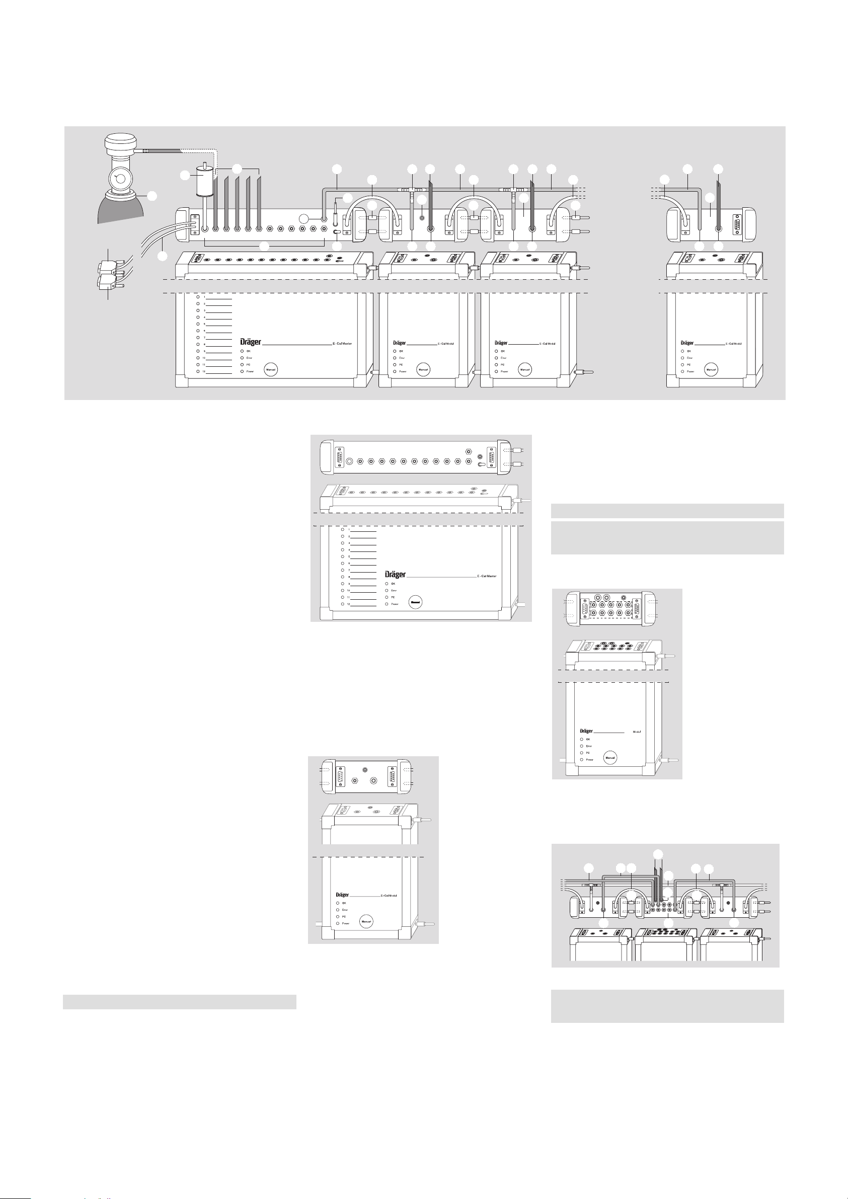
Aufbau
Eine E - Cal Station mit 10 angeschlossenen Gerätemodulen und
Purge Modul beansprucht abhängig vom Typ der erwendeten ECal Gerätemodule von min. 1,9 bis max. 2,9 m, bzw. min. 0,8 bis
max 1,2 qm exkl. PC.
Aufbau erfolgt ausgehend vom E–Cal Master (dargestellt mit 12 Gaseinlassventilen) nach rechts fortsetzend, mit Blick von oben auf die Rückseiten der Module.
Achten Sie auf ausreichenden Platz für den Gesamtaufbau!
E-Cal Master
— E-Cal Master aufstellen.
— PC-Kabel (A) an E-Cal Master (Steckplatz neben Gasaufberei-
tungspatrone (E) ) und PC (COM- oder USB-Port) aufstecken.
Bei manueller Betriebsart entfällt diese Verbindung.
— Gaszufuhrschläuche (B) (nicht mit im Lieferumfang enthalten)
auf die Gaseinlässe (J) stecken und mit dem On Demand Ventil
(C) (Sachnr. 83 16 556) der Gasflasche verbinden.
— Netzteil (D) (Sachnr. 83 15 675) anschließen. Die gesamte
E-Cal Station wird über den E-Cal Master mit Strom versorgt.
— Schutzkappe von der Gasaufbereitungspatrone (E) abnehmen.
Schutzkappe muss nicht wieder aufgesetzt werden.
E-Cal Gerätemodule
— Die den E-Cal Gerätemodulen mitgelieferten Kommunikationskabel
(
F
), Schlauchverbindungen (K) und Abgasschläuche (L) bereitlegen.
— Kommunikationskabel (F) in das E-Cal Gerätemodul und das
linksseitig benachbarte Gerätemodul einstecken.
— T-Schlauchstücke (H) auf die Gaseinlässe (J) der E-Cal Gerätemo-
dule aufstecken (ausser bei letzem E-Cal Gerätemodul rechts).
— Ausgehend vom Gasauslassventil (G) des E-Cal Masters die
E-Cal Gerätemodule mittels der Gaszufuhrschläuche (
K
) über die
T-Schlauchstücke (
H
) verbinden. Gaszufuhrschläuche (K) auf
optimale Länge kürzen, um Knicken der Schläuche zu vermeiden.
— Abgasschläuche (L) in Gasausfuhrbuchsen (M) einstecken.
— Die Abgasschläuche dürfen nicht verlängert werden!
— Verbindungsstifte (N) in die vorgesehenen Stecköffnungen der Gerätemodu-
le (rechte Seitenwand) stecken und Gerätemodul zusammenfügen (optional).
456789101112123
00123869.eps
— Bei Bedarf kann das E-Cal Gerätemodul als Ladestation genutzt wer-
den, indem es über die Netzteilbuchse (
U
) an Strom angeschlossen.
Aufstellen des letztes E - Cal Gerätemoduls (rechtsseitig)
— Der Aufbau erfolgt wie oben beschrieben mit folgender Ausnahme.
— Gaszufuhrschlauch (K) an das T-Schlauchstück (H) des links-
seitigen Gerätemoduls und an den Gaseinlass (J) des E-Cal Gerätemoduls aufstecken.
E-Cal mit Purge Modul (optional)
Das Purge Modul sorgt für die aktive und definierte Absaugung
der Abgase aus der E-Cal Station. Gleichzeitig wird die Ableitung
der Abgase über die Standardlänge des mitgelieferten Ausgangsschlauches hinaus ermöglicht.
Einbau des Purge Moduls (dargestellt mit 10 Einlassventilen) vorzugsweise mittig zwischen die Gerätemodule.
— Die dem Purge Modul mitgelieferten Kommunikationskabel (F)
und Abgasschläuche (P) bereitlegen.
— Abgasschläuche (P) in die Gasausfuhrbuchsen (M) der E-Cal
Gerätemodule einstecken.
— Die freien Schlauchenden der Abgasschläuche (P) auf die
Gaseinlassventile (R) des Purge Moduls stecken.
— Das Purge Modul über die Kommunikationskabel (F) mit den
E-Cal Gerätemodulen verbinden.
Für das letzte Gerätemodul kein T-Stück verwenden!
Hinweis:
Nach Einschalten des E-Cal Masters über den Schalter (O) leuchten alle grünen Power LEDs der angeschlossenen Gerätemodule.
Wichtig:
Nur die dem Purge-Modul beiliegenden Abgasschläuche (mit
Spülöffnung) verwenden
Purge
00323869.eps
_
p
90 23 869 – GA 4634.500 de
© Dräger Safety AG & Co. KGaA
Ausgabe 02 – 02/2009
Änderungen vorbehalten
Dräger Safety AG & Co. KGaA – Revalstrasse 1, D-23560 Lübeck, Germany
Tel. +49 451 8 82 - 0 – Fax +49 451 8 82 - 20 80 – www.draeger.com
500
1000
0
PC-Master auf
COM-Port
PC-Modul auf
COM-Port 2
PS
C
1
E
A
B
J
K H L K H K L
G
121110987654321
O J M J M
F F F
D D
N
U
N N
K L
F
U
MJ
00523869_de.eps
00223869.eps
P P F
P
P
N
M R
L
FNP
F
K
K
S
S
R
P
NN
M
s
de.e
0723869
Page 2
D
— Gasausfuhrbuchse(n) (S) mit Abgasschlauch (L) für die Ablei-
tung nach außen (oder Abzug) bestücken.
— Verbindungsstifte (N) in die vorgesehenen Stecköffnungen des
Purge Moduls (rechte Seitenwand) stecken.
— Purge Modul mit den benachbarten E-Cal Gerätemodulen über
die Verbindungsstifte zusammenfügen.
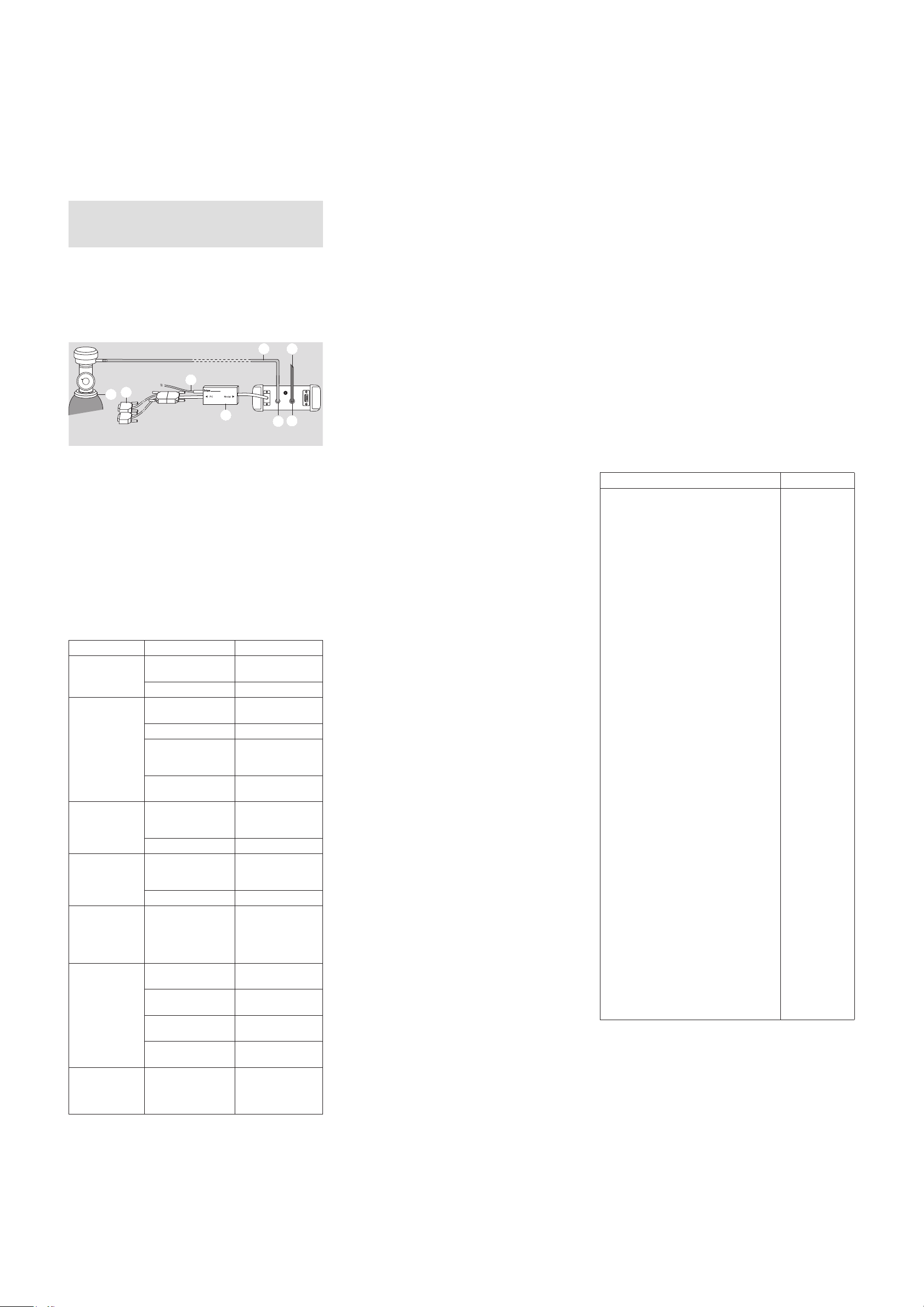
Gerätemodul mit Moduladapter (optional)
D
er Moduladapter ermöglicht den Betrieb eines einzelnen E-Cal Gerätemoduls mit und ohne der PC-Software CC-Vision E-Cal. Eine automatische Umschaltung zwischen Null- und Prüfgas ist hiemit nicht möglich.
E-Cal Gerätemodul im Einzelbetrieb
— PC-Kabel (A) am Moduladapter und PC (COM- oder USB-Port)
aufstecken.
— Für die Gaszufuhr den Gaszufuhrschlauch (K) auf den Gasein-
lass (J) stecken und mit dem On Demand Ventil (C)
(Sachnr. 83 16 556) der Gasflasche verbinden.
— Abgasschlauch (L) auf Gasausfuhrbuchsen (M) aufstecken.
— Moduladapter (T) an E-Cal Gerätemodul (Kommunikation PC)
anschließen.
— Netzteil (Sachnr. 83 15 705) (D) für das E-Cal Modul an den
Moduladapter (T) anschließen.
Verwendung
Siehe Gebrauchsanweisung Dräger CC-Vision.
Störung, Ursache, Abhilfe
Hinweis:
Es müssen immer jeweils 5 Abgasschläuche angeschlossen
werden. Sollten nicht genügend Gerätemodule vorhanden sein,
dann sollten die Schläuche freiliegend angeschlossen werden.
Störung Ursache Abhilfe
Gerät wird nicht
erkannt
Gerätemodul
verschmutzt
Gerätemodul
reinigen
Gerätemodul defekt Dräger Service
Gerätemodul
undicht
Geräte verschmutzt Gerätemodul
reinigen
Dichtung verschlissen
Dichtung austauschen
Rückschlagventil im
Nachbarmodul nicht
in Ordnung
Dräger Service
Verschlauchung nicht
korrekt
Verschlauchung
prüfen
Keine
Kommunikation
Kabel nicht richtig
angeschlossen
Verkabelung zwischen
den Modulen und vom
Master zum PC prüfen
Modul / Kabel defekt Dräger Service
Purge Modul
pumpt nicht
kein Netzteil
angeschlossen
Passendes Netzteil
für Purge Modul
anschliessen
Purge Modul defekt Dräger Service
Ladefunktion des
Gerätemoduls
funktioniert nicht
kein Netzteil
angeschlossen
zum Laden muss
entsprechendes
Netzteil
angeschlossen
werden
Kein Prüfgas
erreicht Gerät
Verschlauchung nicht
korrekt
Verschlauchung
prüfen
Gaskonfiguration
nicht korrekt
gaskonfiguration in
CC-Vision prüfen
Prüfgas leer oder
verschlossen
Prüfgasflasche
prüfen
Gerätemodul
(Pumpe) defekt
Dräger Service
Kalibrierwerte
nicht stabil oder
ungenau
Purge Modul mit
falschen Schläuchen
verwendet
(Unterdruck)
Den im Lieferumfang
des Purge Moduls
mitgelieferten
Schlauch verwenden
Instandhaltung und Wartung
Prüfung vor jeder Inbetriebnahme
Folgende Arbeiten sind vor jeder Inbetriebnahme der E-Cal Station
durchzuführen:
Verschlauchung und Anschlüsse
● Verschlauchung auf Verdreckung/ Versprödung und
Beschädigung prüfen und ggf. auswechseln.
● Festen Sitz der Schläuche prüfen, um Gasaustritt zu vermeiden.
● Überprüfung der Farbe der Trocknerperle:
orange = OK,
farblos = austauschen
● Schnittstellenkabel angeschlossen, ggf. auf festen Sitz prüfen.
Gerätemodule
● Sichtkontrolle Sensorabdichtung der einzelnen Module. (Bei
starker Verschmutzung oder sichtbaren Defekten muss die Abdichtung durch den Dräger Service ausgetauscht werden).
Purge Modul
● Gasabfuhrschlauch angeschlossen zur Abluft, auf Verstopfung
und Beschädigungen prüfen und ggf. auswechseln.
Wartung
Eine Inspektion der gesamten Station ist alle 6 Monate von Fachleuten durchzuführen.
Je nach sicherheitstechnischen Erwägungen,
verfahrenstechnischen Gegebenheiten und gerätetechnischen
Erfordernissen ist die Länge der Inspektionsintervalle auf den
Einzelfall abzustimmen und gegebenenfalls zu verkürzen. Für den
Abschluss eines Service-Vertrages sowie für Instandsetzungen
empfehlen wir den Dräger Service.
Technische Daten
Größe
Master Station (B x T x H) 29 x 29,5 x 6 cm
Purge-Modul 23,5 x 29,5 x 6 cm
Miniwarn Modul (B x T x H) 23,5 x 29,5 x 6 cm
Multiwarn II (B x T x H) 24 x 29,5 x 6 cm
X-am 3000 24 x 29,5 x 6 cm
X-am 7000 24 x 29,5 x 6 cm
X-am 1/2/5000 23,5 x 29,5 x 6 cm
Pac Ex 2 23,5 x 29,5 x 6 cm
PAC III Modul (B x T x H) 13,5 x 29,5 x 6 cm
Pac 1000-7000 29 x 29,5 x 6 cm
Stromversorgung 100 - 240 VAC
CE Kennzeichnung
Elektromagnetische Verträglichkeit (Richtlinie 89/336/EWG)
Lieferumfang
E–Cal Master
— E–Cal Master mit angeschlossener Gasaufbereitungspatrone
— PC-Kabel
— Verbindungsstifte (2 Stück)
— Netzteil (Sachnr. 83 15 675)
— Software
E–Cal Gerätemodul
— E–Cal Modul
— Kommunikationskabel (mit zwei 9-poligen Steckverbindern)
— Abgasschlauch
— Schlauchstück (ca. 25 cm) für die Gaszufuhr
— T-Schlauchstück
Purge Modul
— Purge Modul
— Kommunikationskabel (mit zwei 9-poligen Steckverbindern)
— Abgasschläuche für Kalibriermodule (10 Stück)
— Verbindungsstifte (2 Stück)
Moduladapter
— Moduladapter
— PC-Kabel
— Netzteil (Sachnr. 83 15 705)
Bestellliste
Hinweise zur Entsorgung
Ab August 2005 gelten EU-weite Vorschriften zur Entsorgung von Elektround Elektronikgeräten, die in der EU Richtlinie 2002/96/EG und nationalen Gesetzen festgelegt sind und dieses Gerät betreffen. Für private
Haushalte werden spezielle Sammel- und Recycling-Möglichkeiten eingerichtet. Da dieses Gerät nicht für die Nutzung in privaten Haushalten registriert ist, darf es auch nicht über solche Wege entsorgt werden. Es kann
zu seiner Entsorgung an ihre nationale Dräger Safety Vertriebsorganisation zurück gesandt werden, zu der Sie bei Fragen zur Entsorgung gerne
Kontakt aufnehmen können.
Zubehör Bestellnummer
Dräger E-Cal Master 12 83 16 912
Dräger E-Cal Master 6 83 16 906
Dräger E-Cal Master 2 83 19 090
Dräger E-Cal Purge Modul 83 16 560
Dräger E-Cal Modul Miniwarn 83 16 552
Dräger E-Cal Multiwarn II 83 16 553
Dräger E-Cal Modul X-am 3000 83 17 719
Dräger E-Cal Modul X-am 7000 83 17 705
Dräger E-Cal Modul X-am1/2/5000 83 18 754
Dräger E-Cal Modul Pac Ex 2 83 16 539
Dräger E-Cal Modul Pac III 83 16 554
Dräger E-Cal Modul Pac 1000 - 7000 83 18 589
Modul-Adapter USB 83 19 409
Software Dräger CC-Vision E-Cal 83 16 557
Zubehör/Ersatzteile
Filterscheibe (10 Stück) 56 00 093
Filtervlies für Gasaufbereitungspatrone
(10 Stück)
56 30 250
Rohr für Gasaufbereitungspatrone 56 30 120
Nachfüllpack T-Perlen für
Gasaufbereitungspatrone
56 00 519
O-Ring für Gasaufbereitungspatrone
(2 Stück)
56 30 012
Stopfen für Gasaufbereitungspatrone 56 30 024
Schlauchkupplung 56 10 123
Silikonschlauch, transparent 3 x 2 mm 56 65 090
Schlauch Tygon 4 x 1,6 mm 56 30 058
Membranpumpe 56 30290
Verbrauchsmaterial-Set Purge Modul 56 00 411
Verbindungsstift (2 Stück) 56 10 477
On-Demand Druckminderer 2001 83 16 556
Verbindungskabel zum PC-Master, seriell 56 00 628
Rückschlagventil 56 30 182
Arretierbügel für Multiwarn II 56 10 489
Absaugadapter für Pac 1000 - 7000 56 10 568
LK
500
1000
0
PS
A
C
Anordnung der Komponenten
D
E - Cal Moduladapter
T
M
J
Page 3

D
Dräger E-Cal station, Instructions for use
E–Cal station basic version
Calibration station for portable gas detection units
For your safety
Strictly follow the instructions for use
A
ny use of the calibration station requires full understanding and strict
observation of these instructions.
The calibration station is only to be used for the purposes specified
herein.
Maintenance
Repair of the calibration station may only be carried out by trained
service personnel.
We recommend signing a service contract with Dräger Safety to have all
maintenance jobs carried out.
Only authentic Dräger spare parts may be used for maintenance.
Observe chapter "Maintenance Intervals".
Be sure to read the information contained in the chapter "Maintenance".
Safe connection of electrical devices
Do not connect electrical devices not mentioned in this manual
before contacting the manufacturer or an expert.
Liability for proper function or damage
The liability for the proper function of the calibration station is
irrevocably transferred to the owner or operator to the extent that
the calibration station is serviced or repaired by personnel not
employed or authorized by Dräger Safety or if the calibration
station is used in a manner not conforming to its intended use.
Dräger Safety cannot be held responsible for damage caused by
non-compliance with the recommendations given above.
The warranty and liability provisions of the terms of sale and
delivery of Dräger Safety are similarly not modified by the above
recommendations.
Dräger Safety AG & Co. KGaA
Intended use
E-Cal station is a calibration station with modular structure for
automatic adjustment and function tests of portable gas detection
units.
A system consists of a master station which can switch between 2
and 12 adjusting gases via PC control. Up to 10 modules can be
connected to the master station.
The device modules automatically recognize when a device was
fitted and control the gas supply, ensuring an adequate gas supply
of the device at any time.
A purge module can be used for defined suction of exhaust gases.
The semiautomatic operation of a single device module is possible
by means of a module adapter which facilitates a connection to the
PC as an alternative. The station is controlled by the PC software
CC Vision E-Cal, the software also provides ideal device and data
management.
Design
An E-Cal station with 10 connected device modules und purge
module requires, depending on the type of the used E-Cal device
module, from min. 1.9 up to max. 2.9 m or min. 0.8 up to max 1.2
m
2
exclusive of PC, respectively.
The structure is based on the E-Cal master (shown with 12 gas inlet valves) continuing to the right, with view from top on the rear sides of the modules.
Please pay attention to sufficient space for the entire structure!
E-Cal master
— Set up the E-Cal master.
— Plug the PC cable (A) into the E-Cal master (slot next to gas
processing cartridge(E) ) and PC (COM or USB port). In case
of manual operating mode, the connection is dispensed with.
— Plug the gas supply tubes (B) (not included in the scope of
delivery) onto the gas inlets (J) and connect with the On
Demand valve (C) (Part No. 83 16 556) of the gas cylinder.
— Connect power supply (D) (Part No. 83 15 675). The entire
E-Cal station is powered up via the E-Cal master.
— Remove the protection cap from the gas processing cartridge
(E). The protection cap does not have to be put on again.
E-Cal device modules
— Put out the communication cables (F) supplied with the E-Cal device
modules, tube connections (
K
) and exhaust gas tubes (L).
— Plug the communication cables (F) into the E-Cal device
module and the device module directly on the left side.
— Place the T-tube pieces (H) onto the gas inlets (J) of the E-Cal de-
vice modules (except the last E-Cal device module on the right).
— Connect the E-Cal device modules from the gas outlet valve (G)
of the E-Cal master by means of the gas supply tubes (
K
) via the
T-tube pieces (
H
). Shorten the gas supply tubes (K) to optimum
length in order to prevent folding of the tubing.
— Plug exhaust gas tubes (L) into gas outlet bush (M).
— The exhaust gas tubes may not be extended!
— Insert the connecting pins (N) into the provided openings of the device mod-
ules (right-hand side wall) and assemble the device module (optional).
456789101112123
00123869.eps
— If required, the E-Cal device module can be used as charging cradle
by connecting it to the power supply via the power supply bush (
U
).
Set up the last E-Cal device module (right-hand)
— The set up is carried out according to the above description with the
following exception.
— Plug the gas supply tube (K) onto the T-tube piece (H) of the left-hand
device module and to the gas inlet (J) of the E-Cal device module.
E-Cal with purge module (optional)
The purge module ensures the active and defined suction of the
exhaust gases from the E-Cal station. At the same time, leakage of
the exhaust gases beyond the standard length of the supplied outlet tube is facilitated.
Installation of the purge module (shown with 10 inlet valves) preferably in the centre between the device modules.
— Put out the communication cables (F) and exhaust gas tubes (P)
supplied with the purge module.
— Insert the exhaust gas tubes (P) into the gas outlet bushes (M)
of the E-Cal device modules.
— Insert the free tube ends of the exhaust gas tubes (P) onto the
gas inlet valves (R) of the purge module.
— Connect the purge module via the communication cables (F)
with the E-Cal device modules.
Do not use a T-piece for the last device module!
Note:
After switching on the E-Cal master via the switch (O) all green
power light-emitting diodes of the connected device modules light up.
Important:
Only use the exhaust gas tubes (with flush opening) supplied
with the purge module
Purge
00323869.eps
_
p
90 23 869 - GA 4634.500 en
© Dräger Safety AG & Co. KGaA
edition 02 - 02/2009
Subject to alteration
Dräger Safety AG & Co. KGaA – Revalstrasse 1, D-23560 Lübeck, Germany
Phone +49 451 8 82 - 0 – Fax +49 451 8 82 - 20 80 – www.draeger.com
500
1000
0
PC master on
COM port
PC module on
COM port 2
PS
C
1
E
A
B
J
K H L K H K L
G
121110987654321
O J M J M
F F F
D D
N
U
N N
K L
F
U
MJ
00523869_en.eps
00223869.eps
L
P P F
P
P
N
M R
FNP
F
K
K
S
S
NN
R
P
M
s
de.e
0723869
Page 4

D
— Fit the gas outlet bush(es) (S) with exhaust gas tube (L) for leak-
age towards the outside (or outlet).
— Insert the connecting pins (N) into the provided openings of the
purge module (right-hand side wall).
— Join the purge module with the adjacent E-Cal device modules
via connecting pins.
Device module with module adapter (optional)
The
module adapter facilitates the operation of a single E-Cal device module with or without the PC software CC Vision E-Cal. Automatic switching
between zero gas and test gas is not possible with this.
E-Cal device module in independent operation
— Plug the PC cables (A) onto the module adapter and PC
(COM or USB port).
— For gas supply, plug the gas supply tube (K) onto the gas inlet
(J) and connect with the On Demand valve (C)
(Part No. 83 16 556) of the gas cylinder.
— Plug exhaust gas tube (L) onto gas outlet bush (M).
— Connect the module adapter (T) to the E-Cal device module
(communication PC).
— Connect the power supply (Part No. 83 15 705) (D) for the
E-Cal module to the module adapter (T).
Use
See Dräger CC Vision instructions for use.
Fault, cause, remedy
Note:
Always connect 5 exhaust gas tubes each. If not enough device
modules are available, the tubing should be connected openly.
Fault Cause Remedy
Device not
detected
Device module dirty Clean device module
Device module
defective
Dräger Service
Device module
leaky
Devices dirty Clean device module
Seal worn
Change seal
Check valve in the
adjacent module
faulty
Dräger Service
Tubing not correct Check tubing
No
communication
Cable not connected
correctly
Check cabling
between the modules
and from master to
PC
Module/cable
defective
Dräger Service
Purge module not
pumping
No power supply
connected
Connect matching
power supply for
purge module
Purge module
defective
Dräger Service
Charging function
of the device
module
malfunctioning
No power supply
connected
For charging,
corresponding
power supply must
be connected
Test gas does not
reach device
Tubing not correct Check tubing
Gas configuration not
correct
Check gas
configuration in CC
Vision
Test gas empty or
closed
Check test gas
cylinder
Device module
(pump) defective
Dräger Service
Calibration values
not stable or
inaccurate
Purge module
operated with wrong
tubing (negative
pressure)
Use the tubing
supplied within the
scope of delivery of
the purge module
Maintenance and upkeep
Checks before commissioning
Carry out the following work before commissioning the E-Cal Station:
Tubing and connections
● Check the tubing for contamination, embrittlement and damage
and replace if necessary.
● Check tight fit of the tubing in order to avoid gas leakage.
● Colour verification of the dryer bead:
orange = OK,
colourless = replace
● Interface cable connected, check tight fit if necessary.
Device modules
● Visual inspection of sensor gasket in individual modules.
(In case of heavy contamination or visible defects, the gasket
must be replaced by Dräger Service).
Purge module
● Check the gas supply tube connected for exhaust air for
blockage and damages and replace if necessary.
Upkeep
The entire station must be inspected by competent personnel
every 6 months.
The inspection intervals must be established in each individual
case and shortened if necessary, depending on technical safety
considerations, engineering conditions and the technical
requirements of the equipment. We recommend that a service
agreement be concluded with Dräger Service and that repairs also
be carried out by them.
Technical data
Size
Master station (W x D x H) 29 x 29.5 x 6 cm
Purge module 23.5 x 29.5 x 6 cm
Miniwarn module (W x D x H) 23.5 x 29.5 x 6 cm
Multiwarn II (W x D x H) 24 x 29.5 x 6 cm
X-am 3000 24 x 29.5 x 6 cm
X-am 7000 24 x 29.5 x 6 cm
X-am 1/2/5000 23.5 x 29.5 x 6 cm
Pac Ex 2 23.5 x 29.5 x 6 cm
PAC III module (W x D x H) 13.5 x 29.5 x 6 cm
Pac 1000-7000 29 x 29.5 x 6 cm
Power supply 100 - 240 VAC
CE marking
Electromagnetic compatibility
(Directive 89/336/EEC)
System Components
E-Cal master
— E-Cal master with connected gas processing cartridge
— PC cable
— Connecting pins (2 pieces)
— Power supply (Part No. 83 15 675)
— software
E-Cal device module
— E-Cal module
— Communication cable (with two 9-pole plug connectors)
— Exhaust gas tube
— Tube piece (approx. 25 cm) for gas supply
— T-tube piece
Purge module
— Purge module
— Communication cable (with two 9-pole plug connectors)
— Exhaust gas tubes for calibration modules (10 pieces)
— Connecting pins (2 pieces)
Module adapter
— Module adapter
— PC cable
— Power supply (Part No. 83 15 705)
Order list
Notes on disposal
As of August 2005, the Act Governing the Sale, Return and Environmentally Sound Disposal of Electrical and Electronic Equipment (Electrical
and Electronic Equipment Act - ElektroG), as stipulated in the EC directive
2002/96/EG and corresponding national legislation and concerning this
device will come into effect. Private households will have access to specialized waste disposal und recycling facilities. However, since the device
has not been registered for use in private households, it cannot be disposed of as special household waste. Therefore, you should send it to
your national Dräger Safety distribution organisation for disposal, which
you can contact for further information.
Accessories Order code
Dräger E-Cal master 12 83 16 912
Dräger E-Cal master 6 83 16 906
Dräger E-Cal master 2 83 19 090
Dräger E-Cal purge module 83 16 560
Dräger E-Cal module Miniwarn 83 16 552
Dräger E-Cal Multiwarn II 83 16 553
Dräger E-Cal module X-am 3000 83 17 719
Dräger E-Cal module X-am 7000 83 17 705
Dräger E-Cal module X-am 1/2/5000 83 18 754
Dräger E-Cal module Pac Ex 2 83 16 539
Dräger E-Cal module Pac III 83 16 554
Dräger E-Cal module Pac 1000 - 7000 83 18 589
Module adapter USB 83 119 409
Software Dräger CC Vision E-Cal 83 16 557
Accessories/spare parts
Filter disk (10 pieces) 56 00 093
Filter fleece for gas processing cartridge
(10 pieces)
56 30 250
Pipe for gas processing cartridge 56 30 120
Refill package T-beads for
gas processing cartridge
56 00 519
O-ring for gas processing cartridge
(2 pieces)
56 30 012
Plug for gas processing cartridge 56 30 024
Tube coupling 56 10 123
Silicone tube, transparent 3 x 2 mm 56 65 090
Hose Tygon 4 x 1.6 mm 56 30 058
Diaphragm pump 56 30 290
Consumables set purge module 56 00 411
Connecting pins (2 pieces) 56 10 477
On Demand pressure reducer 2001 83 16 556
Connecting cable to PC master, serial 56 00 628
Check valve 56 30 182
Locking clamp for Multiwarn II 56 10 489
Suction adapter for Pac 1000 - 7000 56 10 568
LK
500
1000
0
PS
A
C
Arrangement of components
D
E - Cal Moduladapter
T
M
J
 Loading...