

Page 1
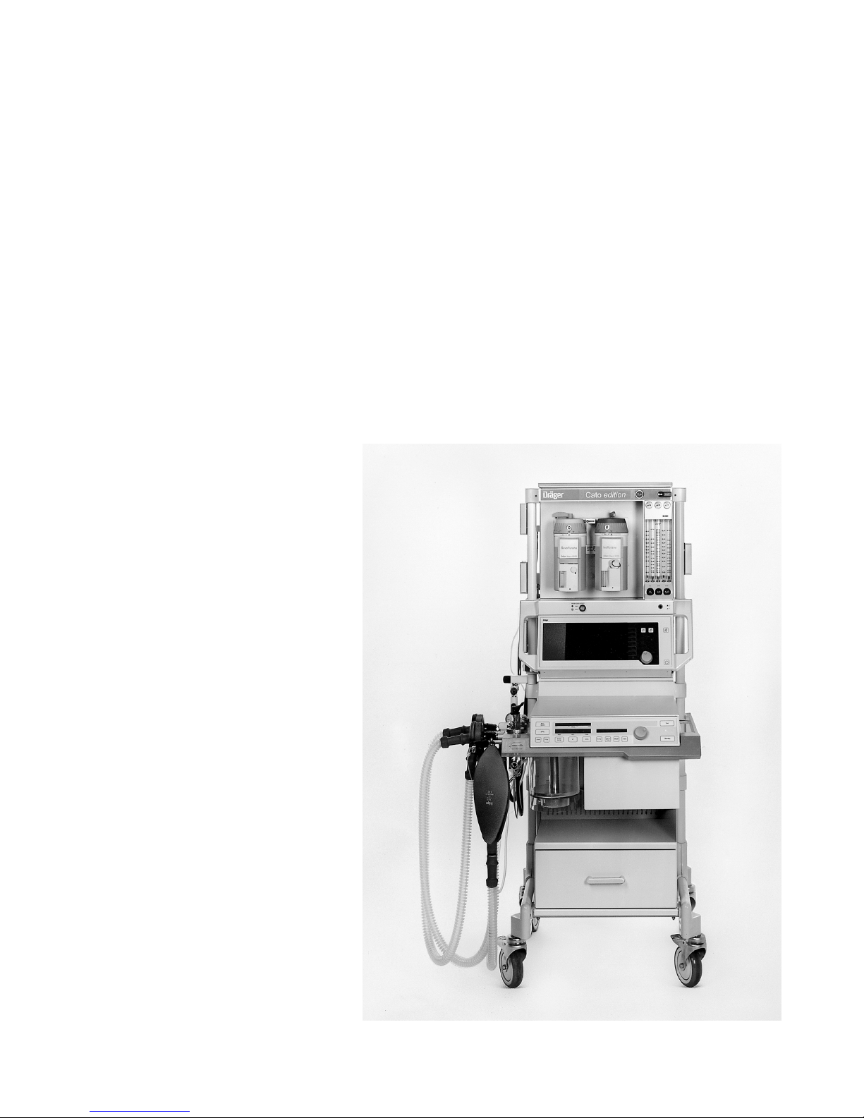
Cato edition
Anaesthetic Workstation
Instructions for Use
Software versions:
Ventilator: ...................... 7.n
Monitor: ......................... 2.n
MT-439-2000
D
Page 2
Working with these Instructions for Use
In the header line...
the subject of the main section
The sub-section title is given underneath the main title to
help you find your way rapidly through the manual.
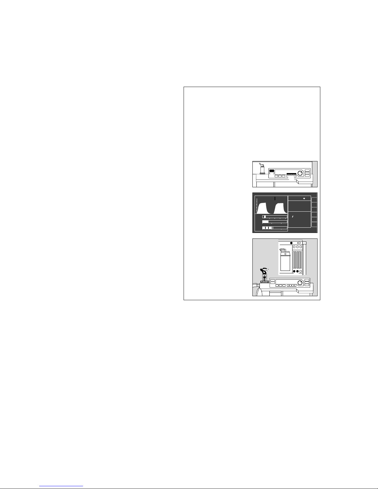
Page body
Instructions for Use
in text-graphic combination. The information is translated
directly into physical actions that teach the user in practical steps how to use the apparatus.
Left-hand column...
the text
contains explanations and guides the user in the operation of the product with concise, clear and unmistakable
instructions in ergonomic sequence.
The bullets (dots) indicate separate steps, and, when
several steps are described, the numbers indicate details
in the illustrations and also specify the order of action.
Right-hand column...
the illustrations
provide a visual reference for the text and make it easier
to locate the various parts of the equipment. Details
mentioned in the text are highlighted. Irrelevant details are
omitted.
The user is also prompted by screen displays which
confirm the operating sequence.
Working with these Instructions for Use
Manual / Spontaneous
Before connecting a patient
● Check workstation with checklist (see page 21).
– Check that breathing system is complete
(see page 20) and
– perform leakage test (see page 31).
Select Manual / Spontaneous mode
1 Press »MAN/SPONT« on ventilator for at least one
second –
2 Display in dialogue field:
MAN/SPONT
The standard screen appears with the alarm limits
for MAN/SPONT mode.
Spontaneous breathing
»PEEP« and pressure limitation »Pmax« are inactive.
3 Set pressure limiting valve APL to »SPONT«.
It is now open, regardless of the set pressure.
To fill system:
4 Press »O2 +« to inflate the breathing bag rapidly –
5 Set fresh gas –
detailed information on setting the fresh gas flow
can be found in the Annex on page 130.
1
2
Operation
Manual / Spontaneous
Select Manual / Spontaneous mode
Spontaneous breathing
alarm
limits
CO
2
al. off
curve
list
alarm
info
Man./spont. alarm limits
SpO2 98 67
etCO2 38
MV 6.0 freq 10
Fi Fet
O
2
29 25
Hal. 0.8 0.6
N2O 70 68
20
18
V
T
0.35
PAW
0
0
Volumeter 27s
5.5
05
10
0.5
1
Volumeter started.
Re-start: confirm !
40
20
CO
2
40
0
config
.
3
4
5
2
00128971 2402897000137224
Page 3

3
Contents
Index 143
Contents
For your safety and that of your patients 4
Quick start in an emergency 7
Operating concept 9
Preparing for use 17
Operation 35
Monitor functions 49
Troubleshooting (messages - cause - remedy) 71
Care 79
Check operational readiness 101
What's what 107
Technical data 115
Descriptions 123
Intended use 5
Page 4

For Your Safety and that of Your
Patients
Strictly follow the Instructions for Use
Any use of the apparatus requires full understanding and
strict observation of these instructions. The apparatus is
only to be used for purposes specified here.
Maintenance
The apparatus must be inspected and serviced regularly
by trained service personnel at six monthly intervals
(and a record kept).
Repair and general overhaul of the apparatus may only be
carried out by trained service personnel.
We recommend that a service contract be obtained with
DrägerService and that all repairs also be carried out by
them. Only authentic Dräger spare parts may be used for
maintenance.
Observe chapter "Maintenance Intervals".
Accessories
Do not use accessory parts other than those in the order
list.
Not for use in areas of explosion hazard
This apparatus is neither approved nor certified for use in
areas where combustible or explosive gas mixtures are
likely to occur.
Safe connection with other electrical equipment
Electrical connections to equipment which is not listed in
these Instructions for Use should only be made following
consultations with the respective manufacturers or an
expert.
Liability for proper function or damage
The liability for the proper function of the apparatus is
irrevocably transferred to the owner or operator to the
extent that the apparatus is serviced or repaired by
personnel not employed or authorized by DrägerService
or if the apparatus is used in a manner not conforming to
its intended use.
Dräger cannot be held responsible for damage caused
by non-compliance with the recommendations given
above. The warranty and liability provisions of the terms
of sale and delivery of Dräger are likewise not modified
by the recommendations given above.
Dräger Medizintechnik GmbH
For Your Safety and that of Your Patients
4
Page 5

Intended use
Anaesthetic Workstation Cato
Universally applicable anaesthetic workstation for
● Inhalation anaesthesia in semi-closed systems
● Inhalation anaesthesia in virtually closed systems with
»low flow« and »minimal flow« techniques for minimum
gas and anaesthetic consumption, with:
● Inhalation anaesthesia in non-rebreathing systems
with separate fresh gas outlet for connecting e.g.
Kuhn system.
● Automatic ventilation (IPPV)
● Synchronized intermittent mandatory ventilation
(SIMV)
● Manual ventilation (MAN)
● Spontaneous breathing (SPONT)
The workstation must only be used under the
supervision of qualified medical staff, so that help is
available immediately if any faults or malfunctions
occur.
Explosive anaesthetic agents, such as ether or
cyclopropane, must not be used due to the risk of fire!
The equipment cannot distinguish between different
anaesthetics. Dräger cannot accept any liability if the
wrong anaesthetic is used!
Additional electric devices clipped into the top of
the unit must be connected to the base unit via an
equipotential bonding (earthing) conductor.
Do not use mobile phones within a distance of
10 metres from the machine.
Mobile phones can cause interference to electrical and
electronic medical appliances, thereby putting patients at
risk.*
Do not use Cato for nuclear spin tomography.
The functioning of the apparatus may be impaired.
Since this equipment is not approved for use with inflammable anaesthetics (ether, cyclopropane, etc.), it is not
necessary to use antistatic (conductive) breathing hoses
or face masks.
Conductive breathing hoses and face masks may cause
burns during high-frequency surgery and are therefore
not recommended for this equipment.
The workstation should be moved using the handles
only.
* Dräger medical appliances comply with the interference immunity
requirements of the specific standards for the products or
EN 60601-1-2 (IEC 601-1-2). However, depending on the design
of the mobile phone and situation of use, field strengths may occur
in the immediate environment of a mobile phone that exceed the
values of the standards quoted and therefore cause interference.
Measurement and monitoring functions:
● Measurement of the ventilation parameters:
pressure, flow, O2 concentration (inspiratory and
expiratory)
● Continuous measurement of the CO2 concentration
and N2O/anaesthetic concentration (halothane, enflurane, isoflurane, sevoflurane, desflurane). The flow
rate for sampling the measuring gas can be varied
and is returned to the circulation.
● Automatic adjustment of the alarm limits for automatic
ventilation IPPV.
● Anaesthetic vaporizer with automatic Vapor
recognition1).
Optional:
❍ Continuous non-invasive measurement of the
functional O2 saturation.
❍ Measurement of the inspiratory breathing gas
temperature.
❍ Expiratory O2 value.
The following values are indicated:
● Continuous curve for airway pressure, peak and
plateau pressure, mean pressure and PEEP.
● Patient compliance.
● Expiratory minute volume, tidal volume and respiration
rate.
● Expiratory flow curve.
● Inspiratory and expiratory O2 concentration.
● Inspiratory and expiratory concentration of N2O and
anaesthetic halothane, enflurane, isoflurane, sevoflurane and desflurane.
● Inspiratory and end-expiratory CO2 concentration
(inCO2 and etCO2).
● Continuous CO2 curve.
● List entries and trend displays.
Optional:
❍ Functional O2 saturation, pulse rate, plethysmogram.
❍ Inspiratory breathing gas temperature.
❍ Expiratory O2 value.
1) Refer to the separate Instructions for Use for the Vapor!
5
Intended use
Anaesthetic Workstation Cato
Page 6

The following parameters are monitored:
● Airway pressure.
● Expiratory minute volume.
● Inspiratory O2 concentration.
● Inspiratory and expiratory CO2 concentration.
● Inspiratory anaesthetic concentration.
Optional:
❍ Functional O2 saturation and pulse.
❍ Inspiratory breathing gas temperature with invariable
upper alarm limit.
Accessories
– Patient monitoring
Optional monitor PM 8060 vitara1).
Parameter box for patient monitoring and measurement of the haemodynamic patient values.
● ECG/arrhythmia analysis.
● Pulse rate.
● Respiration.
● Invasive (2 channels) and non-invasive blood
pressure.
● Functional O2 saturation and pulse.
● Body temperature (2 channels).
– Aquapor
1)
for humidifying and heating the breathing gas.
– Secretion aspirator
1)
– Vapor
1)
Anaesthetic vaporiser for halothane, enflurane,
isoflurane and sevoflurane.
– Connection for two "Vapor" anaesthetic vaporisers
1)
– Devapor
1)
Anaesthetic vaporiser for desflurane.
– Anaesthetic gas scavenging system
1)
– Uninterruptible power supply
1)
1) Refer to the separate Instructions for Use for this equipment!
Intended use
Anaesthetic Workstation Cato
Accessories
6
Page 7
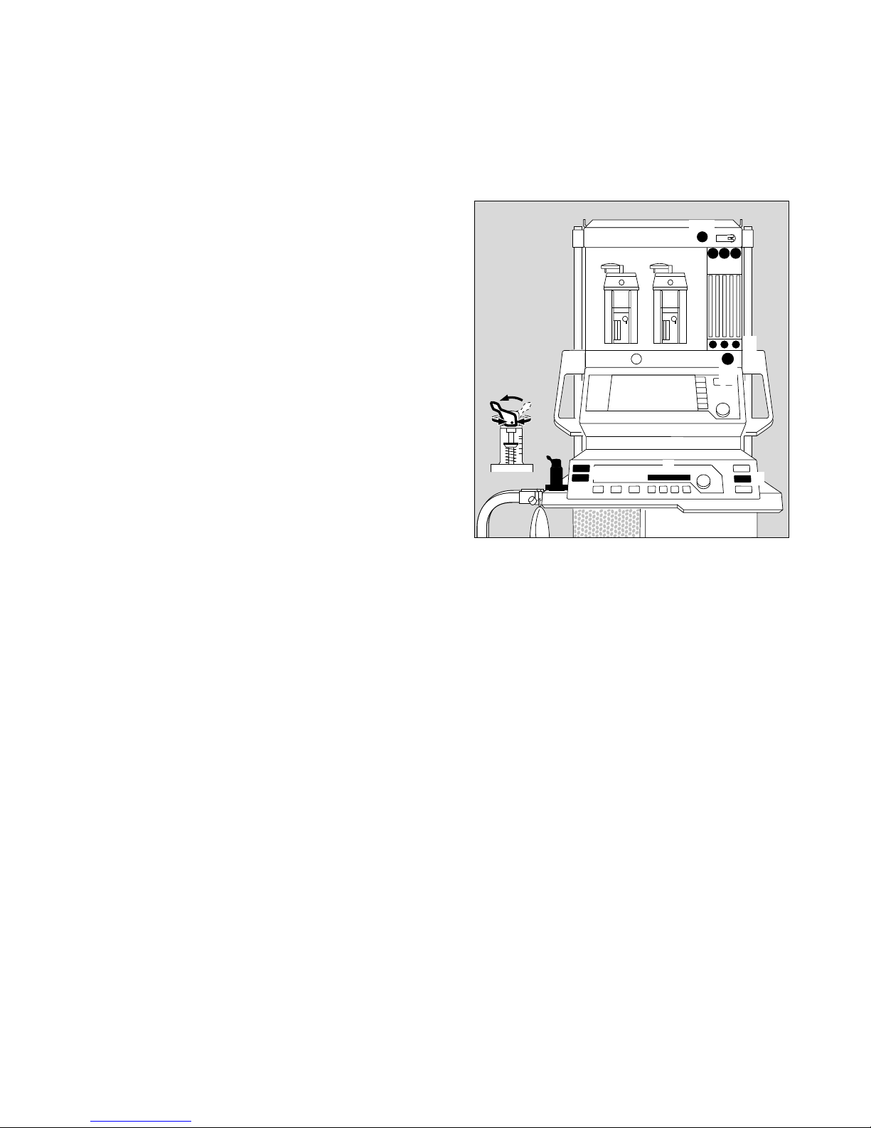
Quick start in an emergency
● Plug the gas connectors into the gas supply wall
sockets.
1 The O2, AIR and N2O pressure gauges must be in
the green range.
● Plug the power plug into the mains.
2 Press the master switch.
All the LEDs on the ventilator light up.
3 Press the key for the desired operating mode on the
ventilator –
Recommendation: hold down M for longer than
1 second.
4 The following message is displayed in the display
window of the ventilator:
Test 3 x discont (example)
Number of times that the self-test has been interrupted for a quick start since it was last completed
successfully.
● Set the selector switch to »N2O« or »AIR«.
5 Deliver fresh gas.
6 Press O2 flush – if necessary –
to fill the system and the breathing bag rapidly.
7 Switch the pressure limiting valve (APL) to »MAN«.
8 Set maximum pressure. Turn the lever of the pressure
limiting valve clockwise until the indicator (plate)
stands at maximum pressure.
No more than ten consecutive quick-starts are allowed
between two complete self-tests. This maximum is only
permitted if the previous completed self-test revealed no
fault.
After the 10th consecutive quick-start, the following
message appears in the ventilator display window:
last cancel
If a further attempt is made to cancel the self-test and carry
out a quick start, the following message is displayed:
COMPLETE TEST
Quick-start not permitted.
A complete self-test must be carried out before startup is possible.
However, in all cases, manual ventilation is always
possible.
Quick-start can be started at any time, even while a selftest is in progress.
D
1
7
8
6
2
5
3
4
3
Cato edition
7
Quick start in an emergency
00237224
Page 8

Power failure (manual ventilation is still possible)
● The master power switch must be pressed.
The audible power failure warning is muted after
45 seconds.
● Deliver fresh gas and set the pressure limiting valve
(APL). If necessary press the O2 Flush key (»O2 +«).
If there is a power failure, the ventilator piston is
forced back to its end position by the airway
pressure, thereby increasing the system volume
by max. 1.4 litre.
Gas failure
If AIR (medical compressed air) fails
– Cato automatically switches over to O2.
If O2 fails
– Cato automatically switches over to AIR. An audible
warning is emitted (O2 shortage warning). N2O
delivery is blocked:
If O2 and air fail:
Ventilate the patient immediately with the
separate emergency ventilation bag!
Auto-WakeUp
Manual ventilation cannot be performed in standby mode.
Any attempt to perform manual ventilation in standby
mode is detected by the system on account of the
pressure thrust in the breathing bag and it automatically
switches to »MAN/SPONT« mode in which manual
ventilation can then be performed. The background
lighting of the flow measuring tubes goes on at the same
time.
The system is protected against excess static pressures:
The system pressure is relieved automatically if an excess
static pressure of more than 30 mbar is present for more
than 60 seconds.
Dräger recommends that manual ventilation should
always be started by pressing the »MAN/SPONT« key.
8
Quick start in an emergency
Power failure
Gas failure
Auto-WakeUp
[
[
Page 9

Contents
Page
Operating concept, general ................................................................... 10
Master switch for electricity supply .......................................................... 10
Operating concept of the ventilator ...................................................... 11
Keys with dedicated function ................................................................... 11
Display window without dialogue function ................................................ 12
Display window with dialogue function .................................................... 12
Operating concept of the monitor ......................................................... 13
Keys with dedicated function ................................................................... 13
Displays .................................................................................................. 13
Measured values with grey numerals ....................................................... 13
Screen structure ..................................................................................... 14
Screen saver ........................................................................................... 14
Rotary control.......................................................................................... 14
The various screen displays .................................................................... 16
9
Operating concept
Contents
Operating concept
Page 10
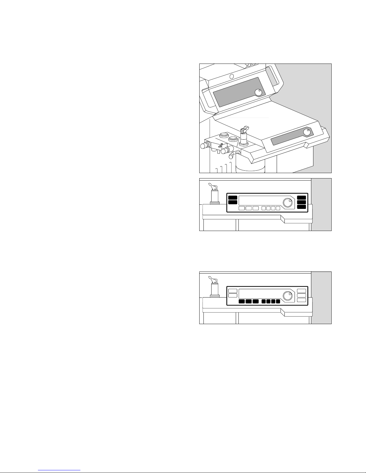
Operating concept, general
Master switch for electricity supply
Master switch
1 Press to switch on
Dialogue:
Monitor and ventilator feature a dialogue with the user
mediated by:
● keys,
● rotary controls,
● displays and
● beeps.
Basic conditions of the operating state are
established by adjusting the delivery valves
or pressure limitation (e.g. APL valve).
● Keys: For direct command input
● Rotary control:
For selection by ...
... turning
This causes a cursor frame (on the screen)
to be moved or a variable numerical value
(on the display window of the ventilator or
on the screen) to be changed.
... pressing
The value selected with the rotary control
is adopted as a valid parameter or a
process is started or ended.
● Displays: For presenting all information on the
screen and on the display windows of the
ventilator.
● Tone sequences:
As an acoustic supplement to the
messages. They are coupled with certain
sounds or tone sequences, according to
priority classes.
Tone sequences accompanying warnings
are output continuously, every 30 seconds
with caution messages and only once in
conjunction with advisory messages.
These are to draw the user's attention to
the messages which appear simultaneously in the displays.
European Standard EN 740 stipulates use
of EN tones.
Alternatively there are tones in keeping
with Dräger conventions available.
1
Operating concept
Operating concept, general
Master switch for electricity supply
10
IPPV
MAN
SPONT
003372242432897000328970
Page 11
Operating concept of the ventilator
Keys with dedicated function –
for setting the operating modes
Left-hand side:
Key for manual ventilation or
spontaneous breathing.
Key for IPPV mode.
Right-hand side:
Key for leakage test and compliance
measurement.
Key for SIMV mode.
Standby key.
for setting ventilation parameters
Below the display window:
Key for setting the maximum pressure
for IPPV and SIMV ventilation.
Key for setting the tidal volume.
Key for setting the ventilation frequency
in IPPV mode.
Key for setting the time ratio between
inspiration and expiration.
Key for setting the relative inspiratory
pause.
Key for setting the PEEP pressure for
IPPV mode.
Key for setting the ventilation frequency
in SIMV mode.
11
Operating concept
Operating concept of the ventilator
Keys with dedicated function
M
I
T
S
A
p
B
F
t
†
P
f
G
A
S
004372240052897000628970
Page 12
Operating concept
Operating concept of the ventilator
Display window without and with dialogue function
12
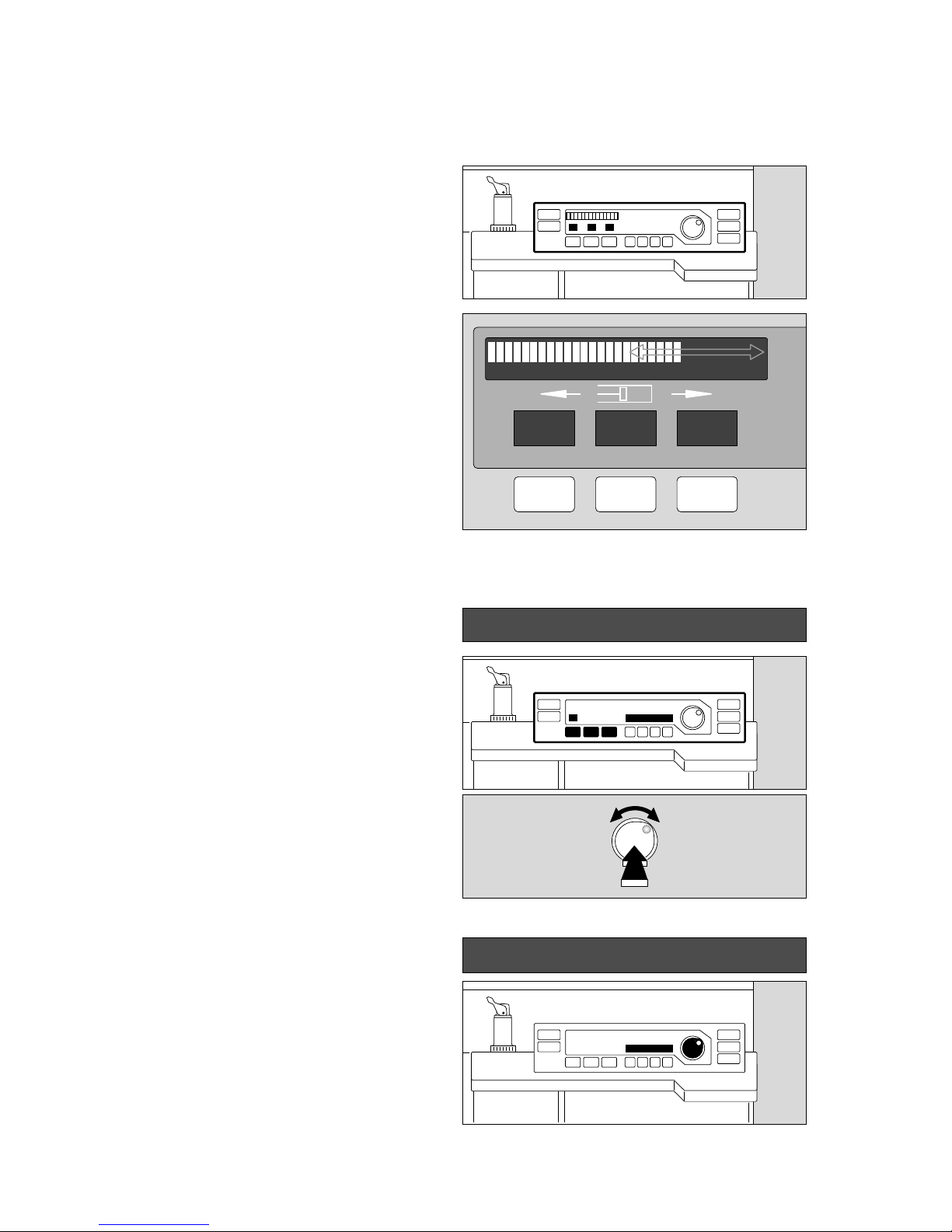
Display window without dialogue function
Top left:
Continuous indication of the relative piston movement
(in % referred to the set stroke volume VT)
The set operating parameters correspond with the keys
below:
– Indication of the maximum pressure Pmax in mbar.
– Indication of the tidal volume VT in mL or L.
– Indication of the ventilation frequency fIPPV in breaths
per minute.
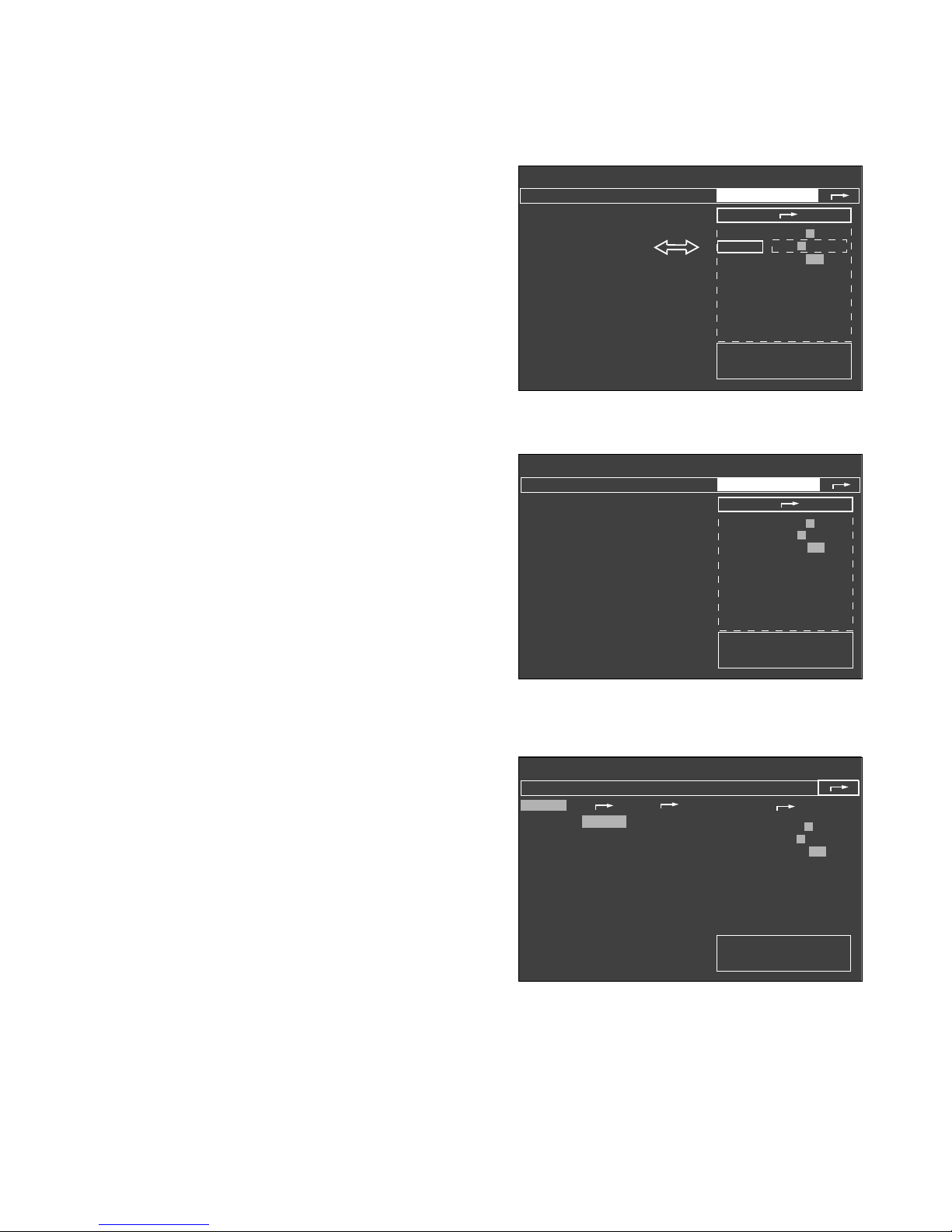
Display window with dialogue function
(in combination with the rotary control)
Example: adjusting the maximum pressure
In the black field, beside the rotary control:
1 The set value appears on the right and left-hand sides
of the field when a parameter key (Pmax, VT, fIPPV) is
pressed. Here: »23«.
2 The value on the right-hand side is changed by turning
the rotary control. Here: »28«.
The old and new values are consequently always
displayed together.
3 The value on the right («28«) is confirmed as the
definitive value by pressing the control.
If the rotary control is not pressed and not turned again,
the machine is reset after 10 seconds without changing
the setting.
● This dialogue window also displays advisory messages
(see page 78) –
Example: »Paed. hoses !«:
23 Pmax / mbar 28
Paed. hoses !
2
3
1
0% 100%
Pmax
23
VT
600
fIPPV
12
mbar ml/L 1/min
0072897000828970009289700102897001128970
Page 13
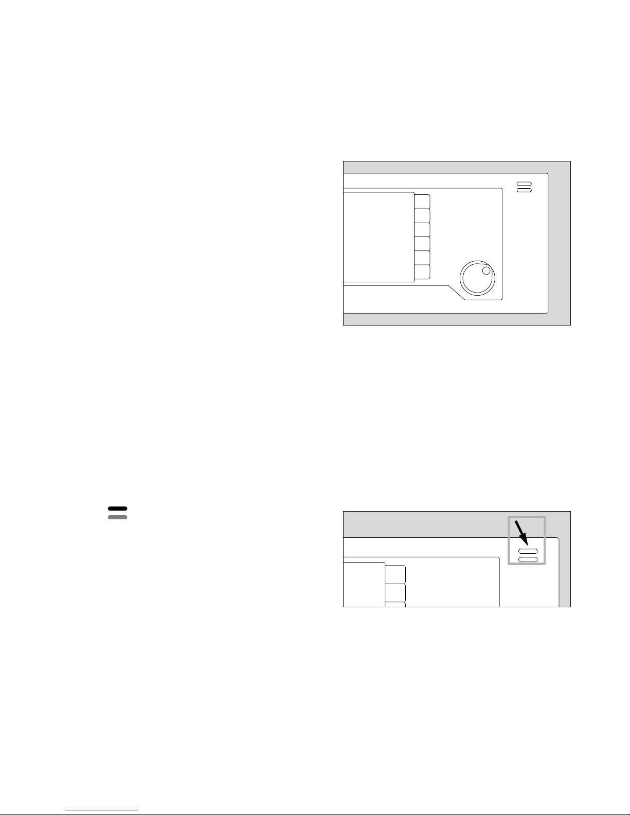
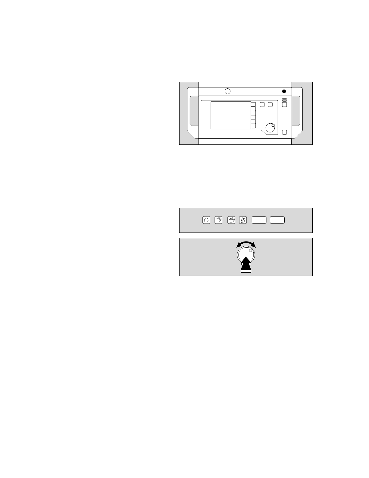
Operating concept of the monitor
Keys with dedicated function (Hardkeys)
The right-hand side is reserved for operating elements,
the left-hand side for displays.
This key switches the monitor from standby to
measuring mode and vice versa.
The monitor mode depends on the ventilator
mode:
Standby can only be selected on the monitor if
the ventilator is also in standby.
The monitor starts up when the ventilator is
started.
This key is used to deactivate the alarm tone for
two minutes. It is reactivated by pressing the key
again. The yellow LED in the key lights up while
alarms are suppressed.
Inside the dark area, there are two keys acting directly on
the screen contents:
This key is used to switch directly from one
screen to the next in succession.
This key is always used to call up the »Standard
screen« (see page 57).
Displays
Two bar-shaped indicator lamps are located above
the G key: these lamps continue to indicate the
alarm states even when the acoustic alam is
switched off.
Red (upper) lamp, flashing: Warning !!!
Yellow (lower) lamp, flashing: Caution !!
Yellow lamp, constant: Advisory !
Measured values with grey numerals
Measured values generated by an uncalibrated sensor
are shown in grey type. This may be due to the following
causes:
– Self-test has been aborted.
– Automatic sensor calibration is in progress.
– The measuring equipment for the anaesthetic gas
composition has not yet reached the required working
temperature when the system is started.
13
Operating concept
Operating concept of the monitor
Keys with dedicated function, Displays
Measured values with grey numerals
E
G
W
Q
E
G
QW
G
QW
01228970
00537224
01428970
Page 14
Operating concept
Operating concept of the monitor
Screen structure, Screen saver
Rotary control
14
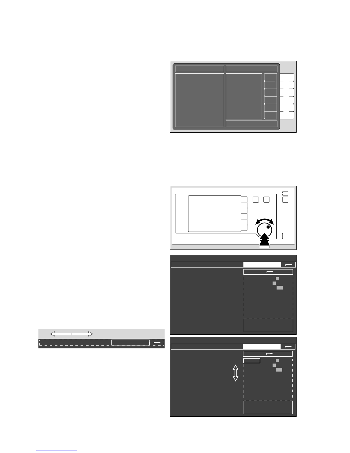
Screen structure
● Status field top:
contains information on the current alarm mode
of the monitor.
● Alarm field top:
indicates any alarms and their priority.
● Graphic field left:
for curves and bar graphs.
● Measured value field right:
for the most important numerical values.
● Operator prompts bottom right:
prompts to guide the operator.
● Softkeys right:
for rapid selection of the functions displayed on the
screen.
Screen saver
If none of the operating elements on the monitor is
operated in »standby« for approx. 2 minutes, the screen
switches off and becomes dark. The yellow LED in the
standby key and the word »standby« on the ventilator
light up. The monitor display is immediately restored as
soon as any key is pressed.
Rotary control
Selection and adjustment with a single control.
For example:
Adjusting the volume of the pulse tone
after calling up the menu of default values via the softkey
»config.« in standby (after entering a code).
● Turn rotary control = selection.
The cursor frame moves horizontally in the dashed
area.
● Press rotary control = confirm selection.
The selection is confirmed and appears in dark type
on a light background. The cursor frame is positioned
over the arrow symbol ( z) to the next higher menu.
● Turn rotary control = the cursor frame moves vertically
inside the dashed area.
Select pulse tone.
anaesth. gas
warning calibrating
defaults
Standby / Configuration
Alarms inactive!
anaesth. gas
warning calibrating
defaults
pulse tone
0 1 2 3 4 5 6 7 8 9
alarm tone 1 2 3 4 5 6 7 8 9
mode adult Neo.
parameters
record
interfaces
alarm limits
curves
basic configuration
Standby / Configuration
Alarms inactive!
anaesth. gas
warning calibrating
defaults
pulse tone
0 1 2 3 4 5 6 7 8 9
alarm tone 1 2 3 4 5 6 7 8 9
mode adult Neo.
parameters
record
interfaces
alarm limits
curves
basic configuration
Menu for setting
pulse tone volume.
Status field Alarm field
Measured
value field
Operator prompts
Graphic field
Softkeys
002289710032897100428971
00528971
01628970
Page 15
● Press rotary control = confirm selection.
The selection is confirmed and appears in dark type
on a light background.
● Turn rotary control = select new setting.
● Press rotary control = confirm selection.
The cursor frame is now on the arrow symbol ( z)
to the next higher menu.
● Turn rotary control = select new setting.
Or:
● Press rotary control again = close submenu
»defaults«.
The cursor frame is on the arrow symbol ( z)
to the next higher menu.
The current configuration is indicated by the fields with
grey background.
● Press rotary control again = exit menu.
15
Operating concept
Operating concept of the monitor
Rotary control
Standby / Configuration
✓
anaesth. gas
Halothane
Enflurane
Isoflurane
Sevoflurane
Desflurane
no
anaesth. gas
warning
default
✓
calibrating
O
2
-sensor
21 Vol.%
flow sensor
Ventilator
start up test
more
✓
Alarms inactive!
defaults
pulse to.
0 1 2 3 4 5 6 7 8 9
alarm tone 1 2 3 4 5 6 7 8 9
mode adult Neo.
parameters
record
interfaces
alarm limits
curves
basic configuration
Standby / Configuration
Alarms inactive!
anaesth. gas
warning calibrating
defaults
pulse tone
0 1 2 3 4 5 6 7 8 9
alarm tone 1 2 3 4 5 6 7 8 9
mode adult Neo.
parameters
record
interfaces
alarm limits
curves
basic configuration
Menu for setting
pulse tone volume.
Standby / Configuration
Alarms inactive!
anaesth. gas
warning calibrating
defaults
pulse tone
0 1 2 3 4 5 6 7 8 9
alarm tone 1 2 3 4 5 6 7 8 9
mode adult Neo.
parameters
record
interfaces
alarm limits
curves
basic configuration
006289710072897100828971
Page 16
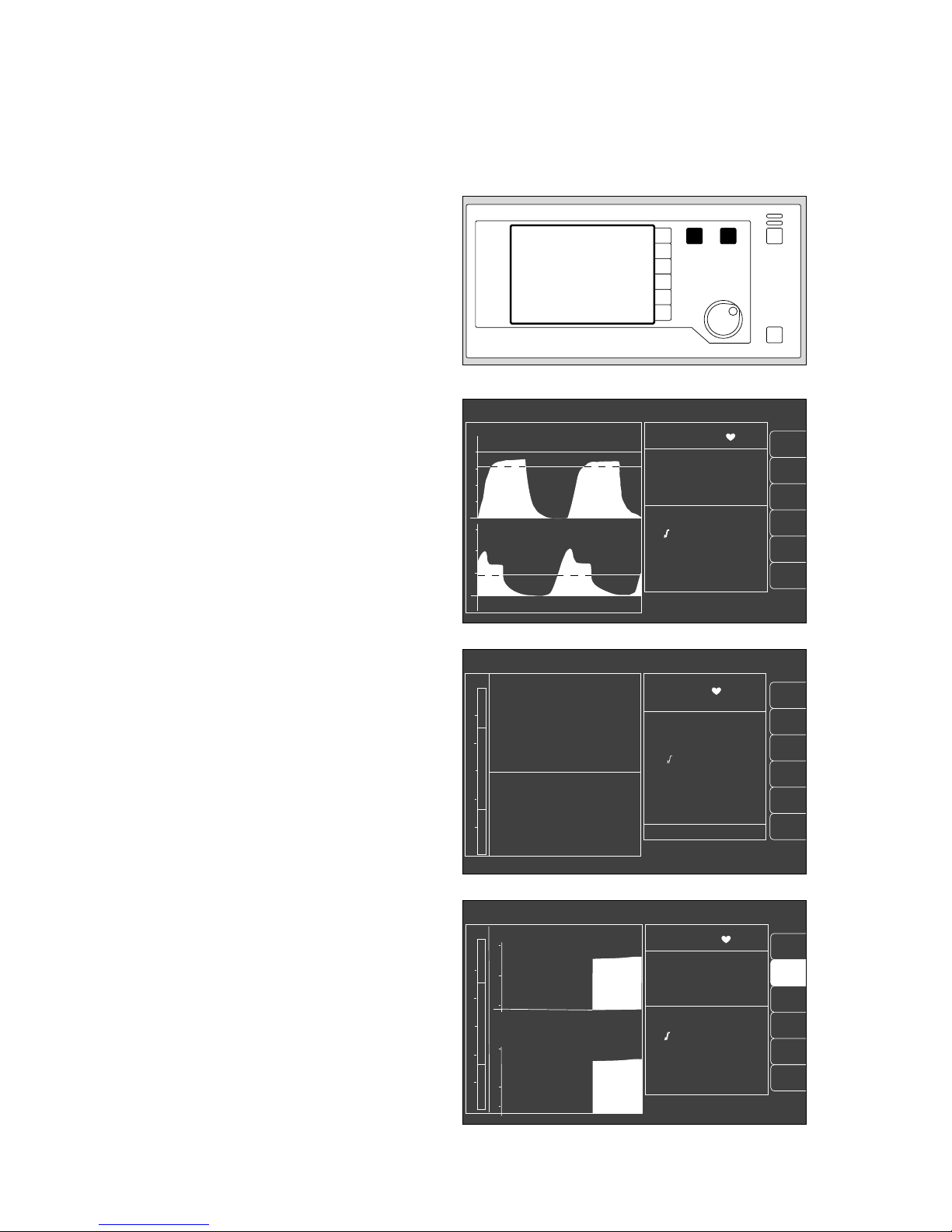
The various screen displays
1 The three different screen displays are invoked by
pressing W.
2 Press Q to return to the standard screen from any
screen display.
The standard screen
with the CO2 curve and another selectable curve. The
most important measured values are grouped together
on the right.
The data screen
contains all measured values with their units of measure;
simplifies the completion of the anaesthesia record.
The trend screen
for displaying the changes in measured values since
measurement started.
The current measured values are shown on the right.
Operating concept
Operating concept of the monitor
The various screen displays
16
alarm
limits
auto set
vent. al.
list
IPPV alarm limits
alarm
info
10 - 03 - 97 8:00
PAW
peak 37 mbar
plat. 30
PEEP 5
mean 20
compliance 15 ml/mbar
MV 6.0 L/min
V
T
0.60 L
freq 10 1/min
AW-temp 38
o
C
20
40
0
Fi Fet
SpO
2
98 67
% 1/min
0 36
29 25
0.8 0.6
70 68
CO
2
mmHg
O
2
%
Hal.
%
N2O
%
sys-compl. 1.5 from 10-03
leakage 5 8 : 00
18
config.
alarm
limits
auto set
vent. al.
curve
list
config.
alarm
info
IPPV alarm limits
SpO
2
98 67
etCO
2
38
MV 6.0 freq 10
Fi Fet
O
2
29 25
Hal. 0.8 0.6
N
2
O 70 68
CO
2
40
0
PAW
20
0
20
18
SpO
2
pulse
AGas
N
2
O
IPPV alarm limits
CO
2
MV
O
2
compl.
SpO
2
98 67
etCO
2
38
MV 6.0 freq 10
Fi Fet
O
2
29 25
Hal. 0.8 0.6
N
2
O 70 68
18
MV
15
5
0
CO
2
60
30
0
11:00 12:00 13:00
PAW
20
40
0
10
full
trend
alarm
limits
12
009289710102897101128971 02328970
Page 17

Contents
Page
Connecting the equipment .................................................................... 18
Electricity and gas supply ........................................................................ 18
Auxiliary electrical equipment ................................................................... 18
Anaesthetic gas scavenging system (AGS) ............................................. 19
Anaesthetic agent vaporiser .................................................................... 19
Uninterruptible power supply ....................................................................20
External equipment .................................................................................. 20
Checking readiness for operation with checklist .................................. 21
Vapor ...................................................................................................... 22
Anaesthetic gas scavenging .................................................................... 22
Breathing system .................................................................................... 23
Soda lime ................................................................................................ 23
Emergency ventilation bag ....................................................................... 23
Water traps ............................................................................................. 24
Reserve gas cylinders (optional) .............................................................. 24
Pipelinie gas supply ................................................................................. 24
Gas delivery ............................................................................................ 24
Oxygen Ratio Control (ORC) .................................................................. 25
O2 Flush ................................................................................................. 25
Secretion aspirator (optional) .................................................................. 25
Power supply .......................................................................................... 26
Self-test .................................................................................................. 26
Fresh gas - External outlet (optional) ........................................................ 27
Selecting anaesthetic agent ..................................................................... 28
Automatic calibration of O2/flow sensors ................................................. 29
Manual calibration of the O2 sensor ......................................................... 29
Manual calibration of the flow sensor ....................................................... 30
Ventilator start-up test ............................................................................. 31
17
Preparing for use
Contents
Preparing for use
Page 18
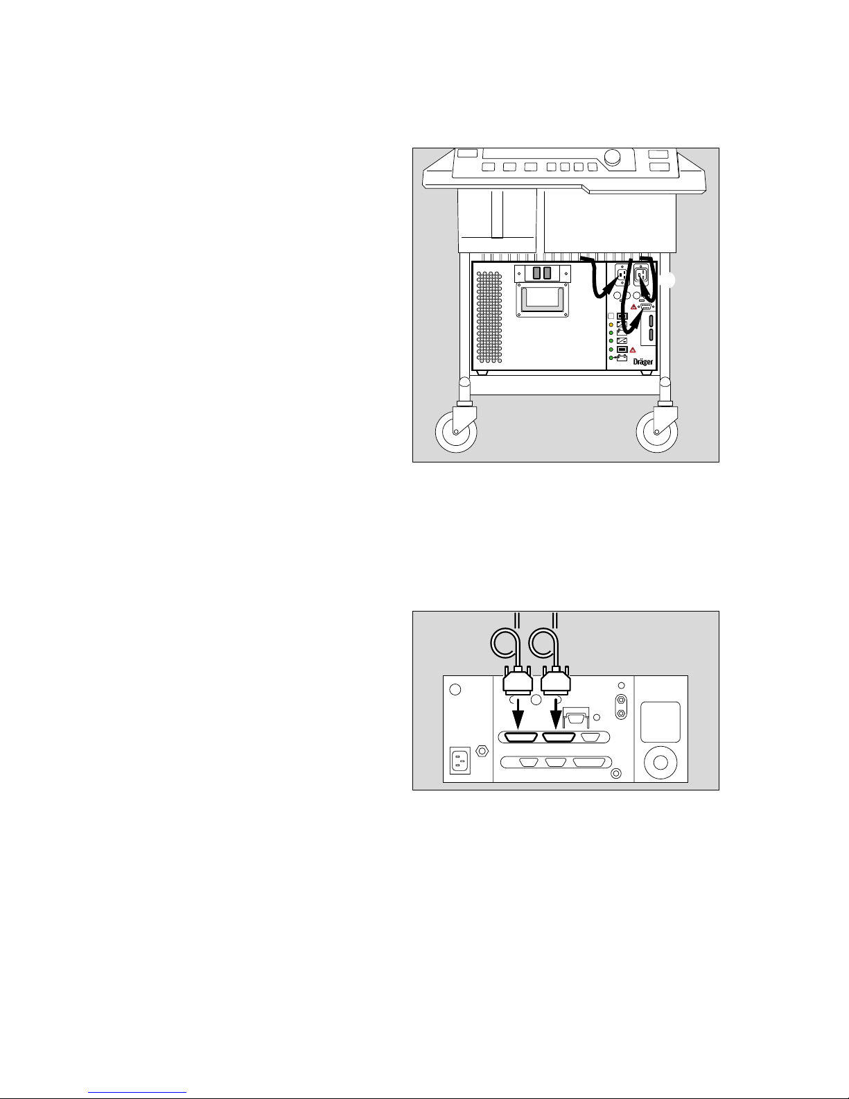
Connecting the equipment
The equipment must have been stripped down and tested
beforehand!
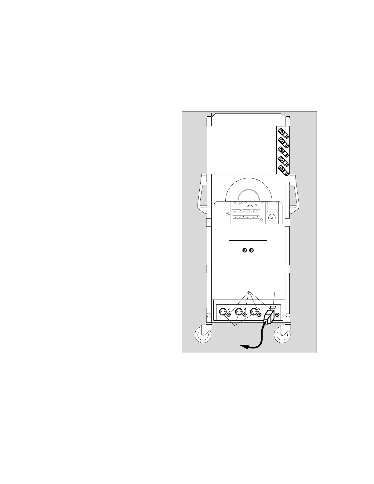
Electricity and gas supply
1 Plug the power cable into the mains socket.
2 Connect a ground lead for equipotential bonding to
one of the four pins on the rear of the workstation
when it is used for intracranial or intracardiac surgery.
The other end must be connected to the specified
point in the operating theatre.
3 Screw hoses for O2, AIR and N2O into the rear of the
equipment and plug connectors into the wall sockets.
● Check that the supply pressure is adequate on the
pressure gauges on the front (pointers must be in the
green area).
4 Holder for anaesthetic gas scavenging.
Auxiliary electrical equipment
5 Connect to the three auxiliary power sockets
(max. current per socket: 2 A). The auxiliary power
sockets are not controlled by the main switch.
If there is a power failure, the auxiliary power sockets
will be de-energised, because they are not powered
by the uninterruptible power supply (UPS).
Do not connect high-frequency surgery appliances to
the auxiliary power sockets.
Do not connect any other multiple sockets, e.g.
multiple socket adapters, to the auxiliary sockets.
The connection of equipment to the auxiliary sockets
causes an increase in leakage current.
The total leakage current in the power line must not
exceed 500 uA (EN 60601-1).
6 Sub-D socket for connecting the uninterruptible
power supply (UPS), see page 20.
On connection to the Sub-D socket, the UPS can be
switched off using the main switch.
The auxiliary power sockets and UPS are not
installed in the Cato ceiling version.
Preparing for use
Connecting the equipment
Electricity and gas supply
Auxiliary electrical equipment
18
1
2P
3
4
6
5
04237224
Page 19
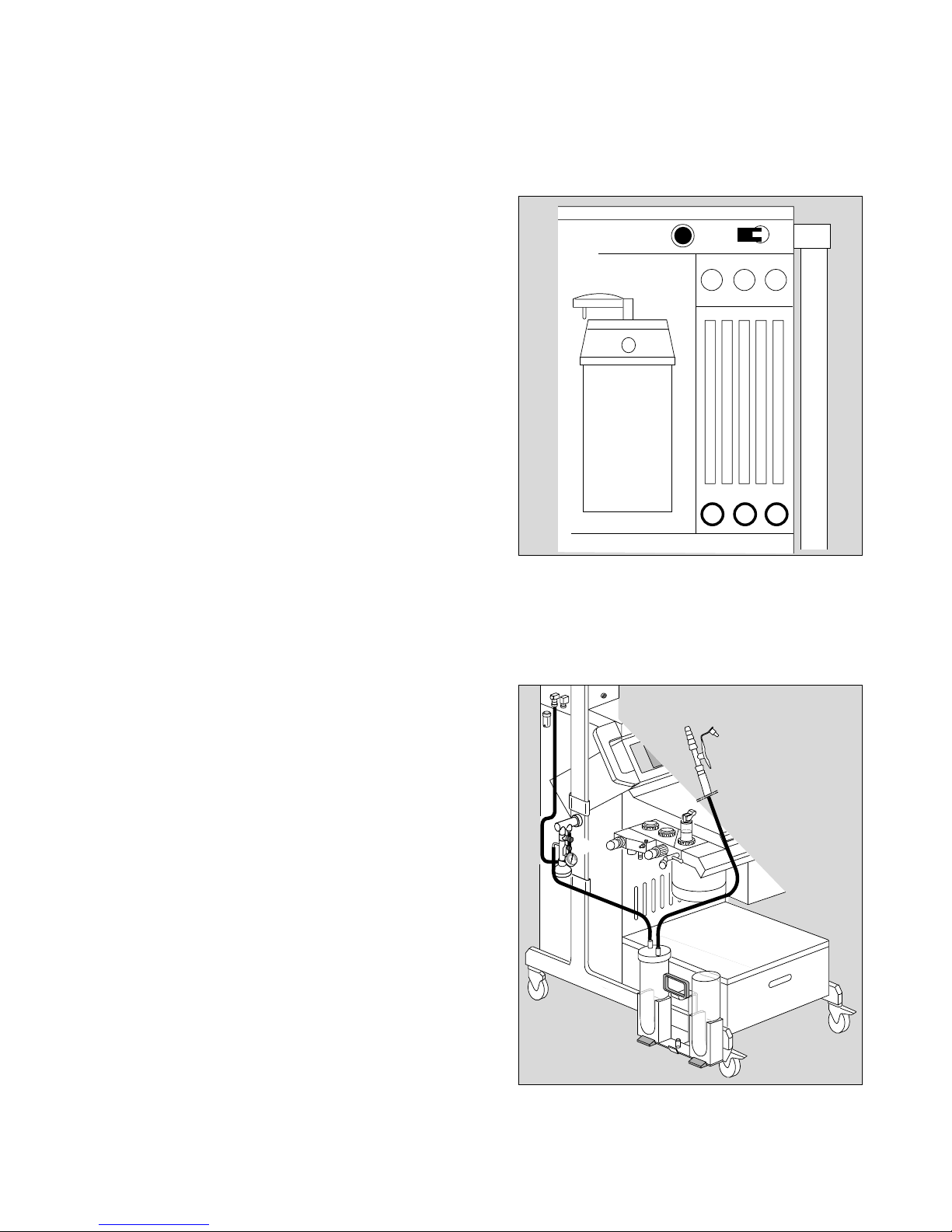
Anaesthetic gas scavenging system (AGS)
● Connect the transfer hose to the scavenging adapter
– first time only, it then remains in place.
1 Insert the scavenging adapter in the breathing system
from below until it engages.
2 Route the transfer hose round the equipment to the
rear.
3 Plug the transfer hose to the port on the collecting
system.
4 Connect the suction hose (sampling hose) to the port
on the collecting system.
5 Connect the anaesthetic scavenging connector to the
sampling hose.
6 Make sure that the second connector on the collecting
system is sealed with the screw plug.
● Follow the specific Instructions for Use of the
anaesthetic gas scavenging system.
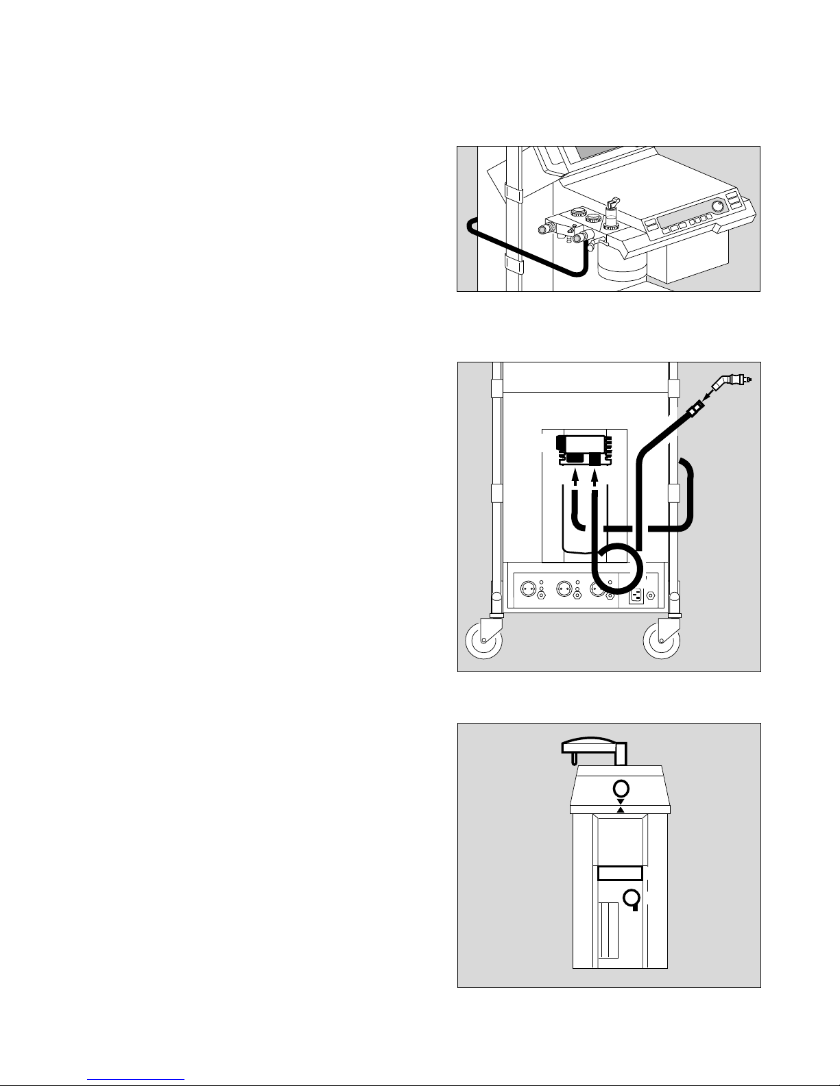
Anaesthetic agent vaporiser
The illustration shows a Vapor 2000
● If using the double connector for two Vapors, the
automatic Vapor identification system is disabled.
● Only use Vapors listed in the Order List.
● Follow the specific Instructions for Use of the Vapor.
● For each anaesthetic agent, only use the specified
Vapor.
7 Always insert the sealing plug and
8 secure with lever.
9 Engage control dial at »0« when no fresh gas is set.
10 Always secure the Vapor with the locking lever (turn
lever to the left as far as it will go).
19
Preparing for use
Connecting the equipment
Anaesthetic gas scavenging system (AGS)
Anaesthetic agent vaporiser
10
9
8
7
0
5
6
34
0292897000637224
G
A
S
1
2
02828970
Page 20
Uninterruptible power supply
(optional, see separate Instructions for Use)
Make sure that the status line is connected, so that the
uninterruptible power supply (UPS) is controlled by Cato.
In the event of power failure, the machine is powered
by the battery of the UPS, but the auxiliary mains
socket on the back of the Cato will be de-energised.
However, auxiliary equipment powered by the refrigerator
connector on the side of the Cato will still be powered.
1 Plug the power plug of the Cato into the socket of the
UPS.
2 Plug the power plug of the UPS into the mains
socket.
The UPS can supply the Cato and connected auxiliaries
with electrical energy for about 45 minutes. It is automatically activated in the event of a power failure.
External equipment
See page 53 for the configuration of the interfaces.
Connection via the protocol interface
3 with data cable for printers with serial interface, e.g.
Desk-Jet (Hewlett-Packard)
or
e.g. the PM 8060 Vitara Patient Monitor with the
MEDIBUS protocol.
See page 53 for configuration.
Connection via the Dräger RS 232 C MEDIBUS
interface
e.g. to connect the PM 8060 Vitara Patient Monitor.
4 Connect with data cable.
● The equipment plugs must be secured with the
screws provided.
Preparing for use
Connecting the equipment
Uninterruptible power supply
External equipment
20
34
g
USV - Ein / On
manuell
S 3 S 4
S 5
S 6
I
0
F2 F2 F3 F4
1
2
0312897003228970
Page 21

Checking readiness for operation
with checklist
It is assumed that the following conditions have
been met:
● The equipment and its accessory parts have been
cleaned and disinfected –
refer to page.......................................... 83 onwards
● The unit is fully equipped for the application in
question –
refer to page.......................................... 89 onwards
● The user has a good knowledge of the Instructions for
Use and has been trained to use the equipment.
● An emergency ventilation bag with appropriate mask is
available on the equipment.
● A checklist is affixed to the equipment.
The equipment must always be checked against the
checklist before it is used!
This check is mandatory as specified by EN 740!
Duration: approx. 5 minutes (depending on the scope
of calibration).
The equipment is subsequently in »standby« mode
when ready for use. Anaesthesia ventilation can
immediately be started at any time in this mode –
refer to page.......................................... 36 onwards
● Update the checklist by adding or deleting points
in accordance with the Instructions for Use, the
equipment type and configuration concerned and the
various supplementary units connected. It will then
contain all the requisite checks.
● Enter the model designation and serial number of the
equipment.
● Tick off ✔ the results of the checks in the ACTUAL
column.
● Remember to sign and date the checklist!
Test sequence
– Note any alterations and additions!
– Note the Instructions for Use of the individual units!
– If the checks do not proceed as planned, restore the
required status.
21
Preparing for use
Checking readiness for operation with checklist
Page 22
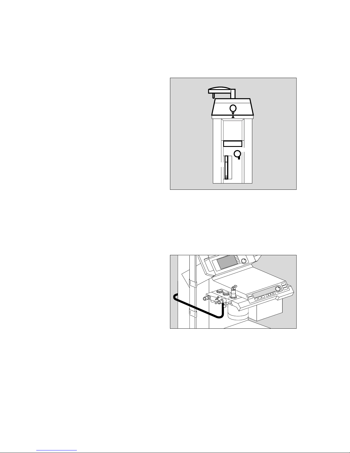
Vapor
The illustration shows a Vapor 2000
1 The control dial is engaged at »0«.
2 Filling level OK – check filling level in viewglass.
– Last inspection less than six months ago.
Safety fill:
3 The sealing plug is inserted and secured with
the lever.
Plug adapter:
– The plug adapter lies horizontally and flush all round
on the sealing rings of the plug connection.
Interlock:
4 Plug-in system is locked – locking lever turned
clockwise until it engages.
Anaesthetic gas scavenging
– Is indicator in wall socket green? (Only when using
Dräger systems; note sounds of gas flow in other
cases.)
– Hose connector engaged below breathing system?
– The auxiliary air holes in the tube below the connector
must not be sealed, otherwise the breathing system
will be drained!
● Note the separate Instructions for Use for the
anaesthetic gas scavenging system.
22
Preparing for use
Checking readiness for operation with checklist
Vapor
Anaesthetic gas scavenging
0
1
4
2
3
D
G
A
S
0073722403428970
Page 23
Breathing system
Lift off table top:
1 Lever set to the position shown in black.
The following are complete:
2 Hose with manual ventilation bag Symbol:
(Connected from below – not shown)
– Correct breathing hoses installed.
(Adult or infant hoses)
3 Pressure measuring hose with filter connected.
4 Measured gas return hose Symbol:
connected.
5 Fresh gas hose plugged in.
(Connected from below – not shown)
6 Valve discs inserted.
– Pressure limiting valve (APL) present.
– Inspiratory microbial filter. Symbol:
– Expiratory microbial filter. Symbol:
Soda lime
7 Lime has not noticeably changed colour (purple).
– Filling level adequate (up to the mark).
– Soda lime container is securely tightened – up to the
end stop (clockwise).
Emergency ventilation bag
(not shown)
– Bag is complete with mask and hung from the side
of the Cato.
– Bag functions correctly.
✔Check and tick off.
23
Preparing for use
Checking readiness for operation with checklist
Breathing system, Soda lime
Emergency ventilation bag
1
275
APL
3
4
6
035289700362897003728970
Page 24
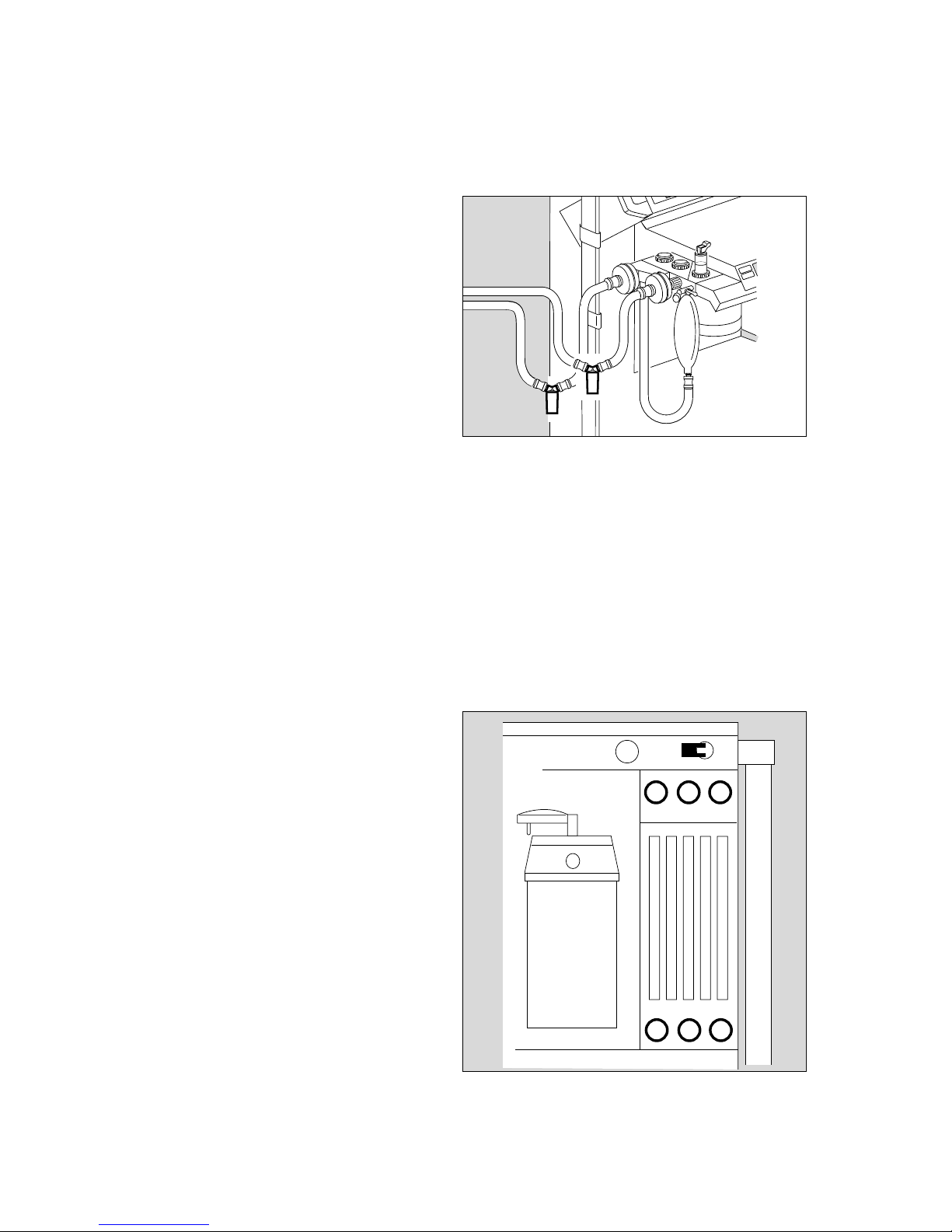
Water traps
1 Water traps are recommended in both the inspiratory
and the expiratory lines during prolonged anaesthesia,
low-flow anaesthesia and when using humidified
breathing gas.
– Water traps must be fitted at the lowest point in the
hose and hang downwards.
– Check regularly and drain if necessary.
Observe hygiene regulations –
risk of infection!
The hose system remains sealed. The container must
be replaced securely!
»Tips on reducing condensation« on page 136.
Reserve gas cylinders (optional)
● Open cylinder valves.
✔Check and tick off:
● Pressure indicator on O2 cylinder exceeds 50 bar? –
Pressure indicator on N2O cylinder exceeds 30 bar? –
Replace cylinders if not.
● Close cylinder valves!
Pipelinie gas supply
● Have connectors been pressed right into the wall
sockets for O2, AIR and N2O (not in holding
position!)?
✔Check and tick off:
2 Pointers of all three pressure indicators are in the
green range.
Gas delivery
3 Switch over to AIR.
4 Open O2 and AIR delivery valves until more than
9 L/min are indicated!
5 Open N2O delivery valve completely.
✔Check and tick off:
Does N2O measuring tube indicate 0?
3 Switch over to N2O.
✔Check and tick off:
Does N2O measuring tube indicate more than 9 L/min?
Does AIR measuring tube indicate 0?
24
Preparing for use
Checking readiness for operation with checklist
Water traps, Reserve gas cylinders
Pipelinie gas supply, Gas delivery
G
A
S
1
1
3
2
445
[
0382897000837224
Page 25
Oxygen Ratio Control (ORC)
1 Slowly close O2 delivery valve –
– check:
the N2O flow decreases to less than 0.8 L/min
proportionally with the O2 flow for ORC low-flow,
the N2O flow decreases to »O« proportionally with
the O2 flow for S-ORC.
2 Switch over to »AIR«.
N2O flow decreases to »O«.
● Close N2O and AIR delivery valve.
O2 flush
3 Press button »O2+« –
– Is there a distinctly audible flow noise?
– Does the manual ventilation bag inflate?
✔Check and tick off!
Secretion aspirator (optional)
4 Open ejector valve –
5 Seal the aspiration holes on aspirator hose with your
finger (or fold over the hose).
Negative pressure indicated approx. – 0.8 bar?
✔Check and tick off!
● Close ejector valve.
Secretion aspirator may only be used in
»MAN/SPONT« mode or with disconnected
Y-piece.
25
Preparing for use
Checking readiness for operation with checklist
Oxygen Ratio Control (ORC)
O2 Flush, Secretion aspirator
D
G
A
S
5
4
2
1
3
[
0093722401037224
Page 26
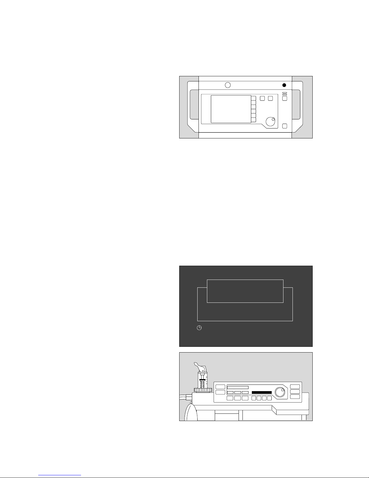
Power supply
● Equipotential bonding conductor connected?
● Mains plug connected?
1 Switch on equipment –
Press main switch to I.
Self-test
✔Check the signals and tick off the following on the
checklist:
● Lamp and alarm test, in succession:
Ventilator:
– Indication of the software version, all indicators light
up for approx. 2 seconds while a single tone sounds.
Monitor:
– The machine runs through the self-test:
All LEDs and display elements light up for
approx. 2 seconds. The LED in the Standby key E
continues to light up.
– Two alarm tones sound.
– The internal program memories are tested.
– The self-test is completed after approx. 1 minute.
The following display appears on the monitor:
»Self-test«
is displayed on the ventilator.
If the self-test reveals a fault of no relevance to the
safety of the equipment and not affecting any of the
measuring functions, the following message appears on
the monitor:
»Ready within limits«
together with a specific error message (refer to
pages 74 onwards). However, the equipment can be
operated nevertheless.
● Press the rotary control.
Call DrägerService.
26
Preparing for use
Checking readiness for operation with checklist
Power supply
Self-test
1
Technology for life
Cato
D
SW-Version 2.05
02-05-00
self-test
00137225 0113722404428970
Page 27
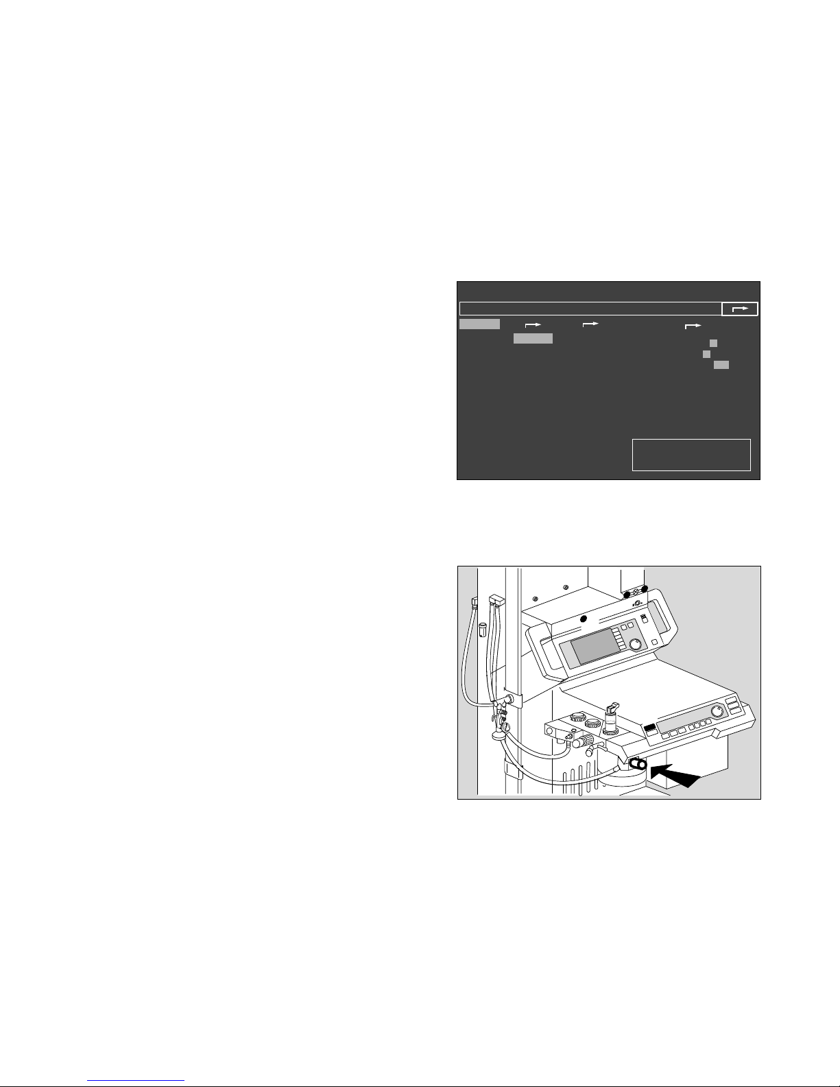
If the self-test reveals a fault impairing the equipment's
safety, the following message appears on the monitor:
»Not ready«.
The machine cannot switch to Standby and cannot be
switched to measuring mode. DrägerService must be
called immediately.
● The configuration menu is displayed after the self-test
(example):
Fresh gas - External outlet (optional)
Fresh gas outlet for connecting to semi-open systems.
1 Fit the hose of the semi-open system to the external
fresh gas outlet.
● Make sure the anaesthetic gas scavenging hose is
connected.
2 Set the desired O2 and N2O flow-rates on the
flowmeter block.
3 Press »MAN SPONT« on the ventilator.
4 The lamp in the »FRESH GAS OUTLET« key does not
light up.
● Check that pressure is building up in the circle system.
4 Switch on the fresh gas outlet –
Press »FRESH GAS OUTLET« key.
The lamp in the key lights up.
● Check that pressure builds up in the semi-open
system.
27
Preparing for use
Checking readiness for operation with checklist
Self-test
Fresh gas - External outlet
Standby / Configuration
✓
anaesth. gas
Halothane
Enflurane
Isoflurane
Sevoflurane
Desflurane
no
anaesth. gas
warning
default
✓
calibrating
O
2
-sensor
21 Vol.%
flow sensor
Ventilator
start up test
more
✓
Alarms inactive!
defaults
pulse to.
0 1 2 3 4 5 6 7 8 9
alarm tone 1 2 3 4 5 6 7 8 9
mode adult Neo.
parameters
record
interfaces
alarm limits
curves
basic configuration
D
P
M
8
050
0
I
G
A
S
1
3
4
2
0132897101237224
Page 28

Selecting anaesthetic agent
The machine automatically identifies the newer Vapor
models with code for
halothane, enflurane and isoflurane,
sevoflurane and desflurane.
Sevoflurane and desflurane are only identified by
equipment built after July 1994 or which has been
upgraded.
Uncoded Vapors must be selected via the configuration
menu on the monitor.
The setting »no anaesth. gas« must be selected in
the configuration menu for ventilation without volatile
anaesthetic. This setting is activated automatically if a
Vapor is not connected.
The plug-in system of the new Vapor models features an
optical code allowing the machine to identify the Vapor:
– when the equipment is started up
– when the Vapor is changed during operation.
Incorrect anaesthetics are not detected!
However, the user can quite deliberately select a
different Vapor instead of that identified automatically.
The following advisory message is then displayed in
the alarm field on the monitor:
»AGT NOT SEL !«
If the Vapor has not been encoded:
The message
»Vapor not identified«
is displayed in the user advisory field of the configuration
menu in »standby« mode.
● Set the appropriate anaesthetic for the Vapor used.
If a Vapor has not been connected:
The message
»Vapor not present«
is displayed in the user advisory field of the configuration
menu in »standby« mode.
28
Preparing for use
Checking readiness for operation with checklist
Selecting anaesthetic agent
Page 29
Automatic calibration of the O2/flow sensors
Sidestream calibration of the O2 measurement
(O2 sampling) and flow measurement are performed
automatically.
Automatic flow calibration is performed during the first
breaths after starting ventilation. There is therefore no
cause for panic if the measured values for the minute
ventilation still appear in grey (i.e. uncalibrated values,
see page 13) immediately after the self-test.
CO2 measurement must function correctly before
automatic flow calibration can be performed, otherwise
the flow sensor must be calibrated by hand.
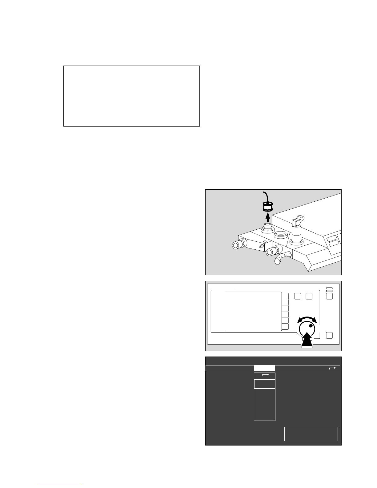
Manual calibration of the O2 sensor
The O2 sensor must be calibrated by hand if
O2 measurement has been set in the inspiratory line
(see “Parameters“ on page 53).
Calibrate O2 sensor with 21% O2 by volume = air
– The O2 sensor can be calibrated while flow calibration
is still in progress.
1 Remove the sensor from the inspiratory valve and
expose it to the ambient air – place it on the table and
wait at least two minutes.
2 Use the rotary control to select »calibrating« in the
»Standby/Configuration« menu and press to confirm.
● Move the cursor frame to
»O2 sensor
21Vol.%« by means of the rotary control.
● Press rotary control to confirm:
calibration starts.
1 Then plug O2 sensor onto the inspiratory valve again.
✔ Tick off in checklist.
29
Preparing for use
Checking readiness for operation with checklist
Automatic calibration of the O2/flow sensors
Manual calibration of the O2 sensor
The following symbols are used:
? = Enquires whether an action has been performed
or a setting made.
u
= Waiting period. The selected test step is being
performed by the machine.
✔ = The action has been completed successfully or
is not required.
Standby / Configuration
Alarms inactive!
calibrating
O
2
-sensor
21 Vol.%
flow sensor
Ventilatorstart up test
more
✓
Calibrate O
2
sensor after
replacing sensor and after 24 hrs.
Detach O
2
sensor and expose
for 2 min. to ambient air.
confirm !
✓
✓
2
G
A
S
1
01428971 0472897004828970
Page 30
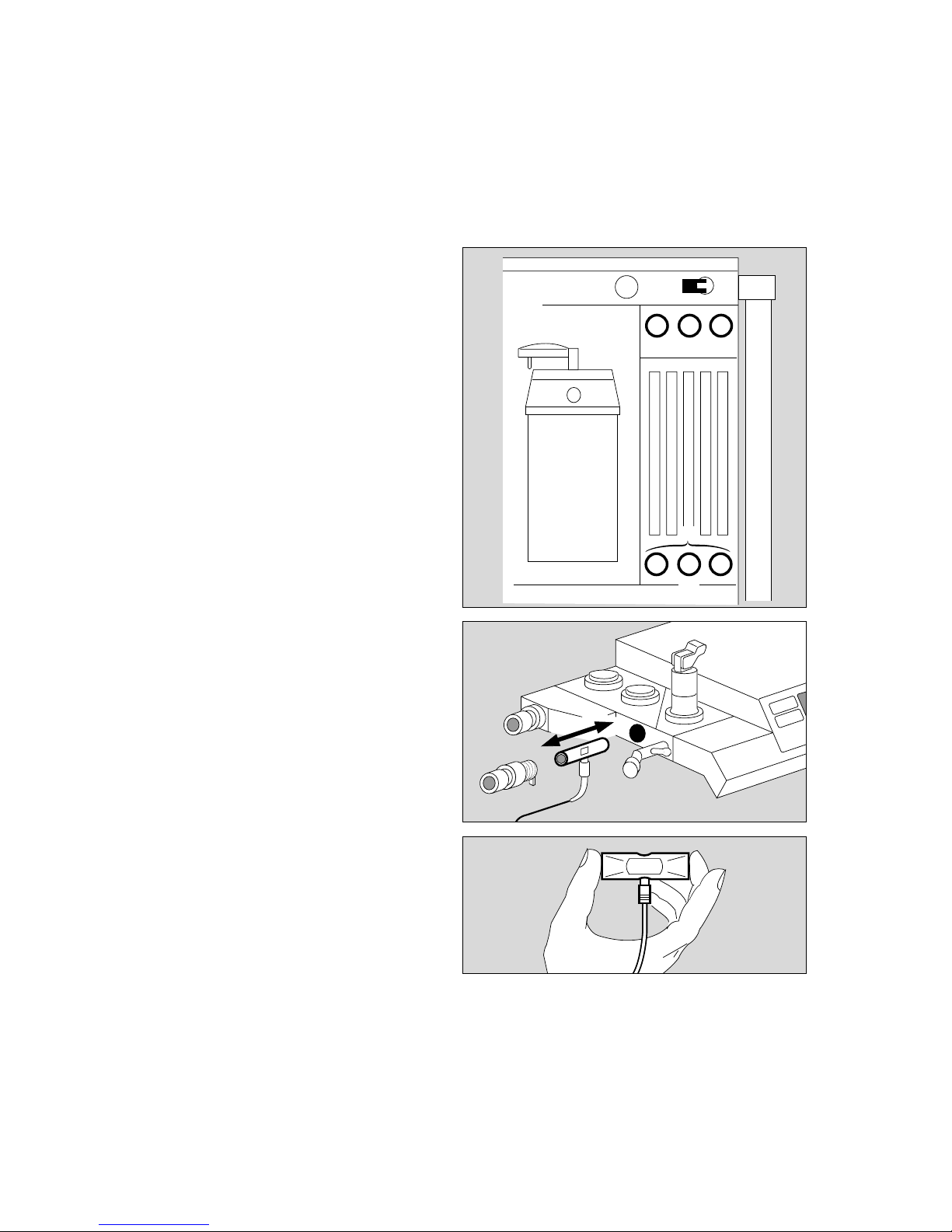
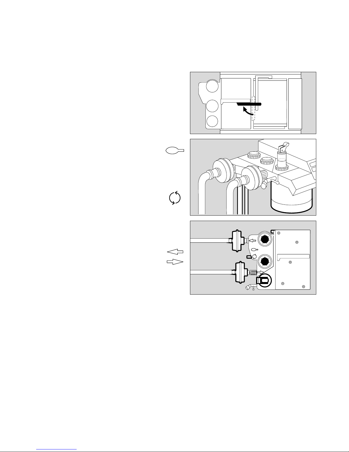
Manual calibration of the flow sensor
– The flow sensor can be calibrated by hand while O2
calibration is still in progress, either in the machine or
after being removed from the machine.
Without removal:
On the anaesthetic unit:
1 Set AIR/N2O selector to »AIR«.
2 Close the delivery valves for O2 and N2O, open the
delivery valve for air and thoroughly flush the
breathing system with air.
3 Close the delivery valve for air.
● Press the rotary control on the monitor to start
calibration.
The question mark (?) disappears and is replaced by
a timer icon ( u) on the screen.
A tick ( ✔ ) appears on the screen when calibration
has been completed correctly.
✔Tick off in checklist.
The cursor frame has automatically jumped to
»Ventilator start-up test«.
With removal:
4 Remove flow sensor:
– Unscrew expiration nozzle
– Remove flow sensor
– Briefly swing it to flush with ambient air
– Hold it horizontally with the cable connection pointing
downwards (calibration in installation position
improves the measuring accuracy)
– Seal off one or both sides as shown on the right,
preferably with your thumb or palm.
● Press the rotary control on the monitor to start
calibration; continue as above.
4 Replace flow sensor!
30
Preparing for use
Checking readiness for operation with checklist
Manual calibration of the flow sensor
4
2
1
3
2
013372240512897005228970
Page 31

Ventilator start-up test
The ventilator must not be connected to the patient
during this test!
Quantitative test to establish the integrity of the
anaesthetic system.
The test cannot be performed until O2 and flow
calibration is complete and the relevant sensors have
been installed in the anaesthetic system.
1 Use the rotary control to select
«Ventilator
start-up test«
under »Calibrating« in the »Standby/Configuration«
menu and press to confirm. (If this has not already
been done automatically after O2 and flow calibration).
● Screen display:
On ventilator:
2 Display: Digits 1 to 10 = test blocks during the self-
test –
refer to the flow chart on pages 124/125 for further
details.
Messages in the display are accompanied by a brief
advisory tone which is repeated every 15 seconds if the
operator does not undertake some kind of action on the
equipment.
The test pressure is displayed as an analog and
digital value.
Display (example):
31
Preparing for use
Checking readiness for operation with checklist
Ventilator start-up test
Standby / Configuration
Alarms inactive!
calibrating
O
2
sensor
21 Vol.%
flow sensor
Ventilatorstart up test
more
✓
Test ventilator after system
start up.
Not possible while operational
✓
?
Standby / Configuration
Alarms inactive!
60 mbar
Pressure in
breathing system
60
0
30
✓
✓
Take note of ventilator information.
Confirm at ventilator!
Calibrating
O
2
sensor
21 vol.%
flow sensor
ventilator
start up test
more
1
2
0152897101628971 0532897005528970
Page 32

The dialogue continues on the ventilator:
1 Test block No. 3 and display:
Fresh gas occl?
3 Close all three delivery valves!
Confirm:
2 Press rotary control on ventilator!
1 Display:
APL = 30 mbar?
4 Set pressure limiting valve to »MAN« and 30 mbar!
Confirm:
2 Press rotary control on ventilator!
1 Display:
Y-piece open?
5 Remove Y-piece from cone or exercise thorax!
Confirm:
2 Press rotary control on ventilator!
1 Display:
Self-test
1 Display:
Ypiece occluded?
5 Plug Y-piece onto cone!
(The sampling line is connected to the Y-piece and
the water trap.)
Confirm:
2 Press rotary control on ventilator!
1 Display with test block No. 4:
Self-test
The test then continues automatically, block by block:
● wait – approx. 1 minute!
1 Display:
Leaktest IPPV
32
Preparing for use
Checking readiness for operation with checklist
Ventilator start-up test
11
2
G
AS
4
5
3
057289700143722405928970
Page 33

1 Display:
Leak IPPV = xxx mL
If greater than 175 mL/min:
Repair leak, particularly for low-flow, or continue if
not problematical –
Confirm:
2 Press rotary control on ventilator!
1 Display with test block No. 9:
Leaktest MAN
1 Display:
Self-test
● Wait – approx. 1 minute!
A tick (✔) appears on the screen when the ventilator test
has been completed successfully.
The prompt »Confirm« appears.
● Press rotary control on monitor.
The cursor jumps to the arrow symbol on the
configuration menu and the vertical pressure indication
disappears.
● Press the rotary control on the monitor again to
confirm and exit the configuration menu. Configuration
is now complete.
✔Tick off the ventilator self-test and monitor self-test on
the checklist.
33
Preparing for use
Checking readiness for operation with checklist
Ventilator start-up test
11
2
Standby / Configuration
✓
anaesth. gas
Halothane
Enflurane
Isoflurane
Sevoflurane
Desflurane
no
anaesth. gas
warning
default
✓
calibrating
O
2
-sensor
21 Vol.%
flow sensor
Ventilator
start up test
more
✓
Alarms inactive!
defaults
pulse to.
0 1 2 3 4 5 6 7 8 9
alarm tone 1 2 3 4 5 6 7 8 9
mode adult Neo.
parameters
record
interfaces
alarm limits
curves
basic configuration
01728971 06028970
Page 34

1 Press rotary control on monitor –
The machine changes to »standby« mode and the
following display appears (example):
2 On the ventilator:
Standby
»Standby« means that:
– the system can immediately be switched to any
operating mode;
– gas consumption is zero (neither drive gas nor
anaesthetic gas);
– power consumption is marginal;
– the piston cylinder unit is in withdrawal position.
Manual ventilation is not possible in standby mode!
Any attempt to undertake manual ventilation in »standby«
mode is immediately detected and causes the system to
start operation in MAN/SPONT mode. (»Auto-WakeUp«
function, see page 8).
The equipment is now ready for operation!
The monitor and ventilator self-tests have been
completed successfully.
✔Tick off in checklist, select the settings required for
the patient and
✔tick off in checklist.
● Remember to sign and date the checklist!
34
Preparing for use
Checking readiness for operation with checklist
Ventilator start-up test
1
erase
trend
Select ventilation mode at the ventilator
or switch on screen by pressing
Standby
Cato
SW-Version 2.05
02-05-00
config.
2
00237225 0622897006428970
Page 35

Contents
Page
Manual / Spontaneous .......................................................................... 36
Select Manual / Spontaneous mode ........................................................ 36
Spontaneous breathing ........................................................................... 36
Manual ventilation .................................................................................... 37
Manual ventilation following a power failure ............................................. 37
Emergency ventilation following a gas failure ........................................... 37
Fresh gas - External outlet (optional) ........................................................ 38
IPPV ....................................................................................................... 39
Selecting IPPV mode .............................................................................. 39
Adjusting ventilation parameters ......................................................... 39
Automatic compliance correction ........................................................ 40
Ventilation with pressure limitation (PCV) ........................................... 40
Limit settings ...................................................................................... 40
SIMV ...................................................................................................... 41
Selecting SIMV mode ............................................................................. 41
Paediatric use ........................................................................................ 42
Anaesthesia ventilation with the Kuhn system .......................................... 43
Monitoring with reduced alarm limits ........................................................ 44
Checking water traps .............................................................................. 44
at the water separator in the gas sampling hose ................................. 44
in the breathing hoses ........................................................................ 44
Checking the soda lime ........................................................................... 45
Anaesthetic vaporiser .............................................................................. 45
Secretion aspirator (optional) .................................................................. 46
Changing patients ................................................................................... 46
Set machine to »standby« ........................................................................ 48
After use ................................................................................................. 48
35
Operation
Contents
Operation
Page 36

Manual / Spontaneous
Before connecting a patient
● Check workstation with checklist (see page 21
onwards).
– Check that breathing system is complete
(see page 23) and
– perform leakage test (see page 31 onwards).
Select Manual / Spontaneous mode
1 Press »MAN SPONT« on ventilator for at least
one second (or press »MAN SPONT« and confirm
with the rotary control. Setting by Dräger Service).
2 Display in dialogue field:
MAN/SPONT
The standard screen appears with the alarm limits for
MAN/SPONT mode.
Spontaneous breathing
»PEEP« and pressure limitation »Pmax« are inactive.
3 Set pressure limiting valve APL to »SPONT«. It is
now open, regardless of the set pressure.
To fill system:
4 Press »O2 +« to inflate the breathing bag rapidly.
5 Set fresh gas –
detailed information on setting the fresh gas flow
can be found in the Annex on page 128.
Operation
Manual / Spontaneous
Select Manual / Spontaneous mode
Spontaneous breathing
36
1
2
alarm
limits
CO
2
al. off
curve
list
alarm
info
Man./spont. alarm limits
SpO
2
98 67
etCO
2
38
MV 6.0 freq 10
Fi Fet
O
2
29 25
Hal. 0.8 0.6
N
2
O 70 68
20
18
V
T
0.35
PAW
0
0
Volumeter 27s
5.5
05
10
0.5
1
Volumeter started.
Re-start: confirm !
40
20
CO
2
40
0
config.
3
4
5
01928971 0652897001537224
Page 37

Manual ventilation
with breathing bag
»PEEP« and pressure limitation »Pmax« are inactive.
The airway pressure is limited via the pressure limiting
valve APL.
1 Set pressure limiting valve APL to »MAN« and set
required ventilation pressure: turn valve head.
To fill system:
2 Press »O2 +«.
3 Set fresh gas with O2, N2O or AIR delivery valve –
● start manual ventilation.
Manual ventilation following a power failure
with breathing bag
(Only relevant if the machine is not equipped with an
uninterruptible power supply).
In the event of a power failure, the airway pressure
pushes the ventilator piston into its limit position, thus
increasing the system volume by up to 1.4 litres!
To compensate this:
1 Set pressure limiting valve APL to »MAN« –
3 temporarily increase fresh gas flow
or
2 press »O2 +«.
3 Set fresh gas with O2, N2O or AIR delivery valve –
● start manual ventilation.
Emergency ventilation following a gas failure
AIR changeover
The ventilator drive and ejector generating a negative
pressure in the secretion aspirator are normally supplied
with gas from the compressed air supply (AIR). If AIR
fails, the system automatically switches over to O2.
N2O lock and O2 shortage alarm
If O2 fails, an O2 shortage is signalled and the supply of
N2O disabled. The measuring tube block automatically
switches to AIR, regardless of the lever setting.
The patient must immediately be ventilated
with the separate emergency ventilation bag
if both O2 and AIR fail.
37
Operation
Manual / Spontaneous
Manual ventilation
Manual ventilation following a power failure
Emergency ventilation following a gas failure
[
1
2
3
01637224
Page 38

Fresh gas - External outlet (optional)
Only available in "MAN/SPONT" mode
1 Connect the anaesthetic gas scavenging hose, see
page 92.
2 Press »MAN SPONT« on the ventilator.
3 Switch on the external fresh gas outlet –
Press »FRESH GAS OUTLET«
The lamp in the key lights up.
The circle system is switched off.
● Perform anaesthesia ventilation using the external
fresh gas outlet.
● When switching over to another mode, e.g. IPPV, the
circle system is automatically switched on again. The
external fresh gas outlet is then disabled.
4 Monitoring the breathing gas (O2 and anaesthetic
gases) in semi-open mode with aspiration
measurement at the fresh gas supply connector of the
semi-open system, and with the screen in HLM mode.
Intake measurement is performed without
connection to the breathing phase. There is no
pressure monitoring.
When switching on and in the event of a power
failure lasting longer than 2 minutes, Cato
switches automatically to the internal fresh gas
outlet.
D
PM
805
0
0
I
G
A
S
2
1
4
3
Operation
Manual / Spontaneous
Fresh gas - External outlet
38
[
0173722407028970
Page 39

IPPV
Selecting IPPV mode
Secretion aspirator may only be used in
»MAN/SPONT« mode or with disconnected
Y-piece.
After switching on, the ventilation parameters set prior to
delivery or subsequently programmed by DrägerService
are active in IPPV mode.
1 Set the values required for the patient.
Default settings upon delivery of new equipment:
(may be altered by DrägerService if requested by
customer)
VT Tidal volume 0.6 L
fIPPV IPPV frequency 12 breaths/min.
Pmax Maximum ventilation pressure 25 mbar
TI:TE Inspiration/expiration time ratio 1 : 1.7
TIP:TI Inspiration pause/inspiration
time ratio 10 %
2 Set PEEP – if necessary.
3 Press »IPPV«.
4 Display in dialogue field:
IPPV Mode ?
5 Press rotary control to confirm –
ventilation starts.
The parameters Pmax, VT, fIPPV, PEEP and piston
movement are displayed on the ventilator.
The monitor is also started and the IPPV alarm limits
are activated.
Adjusting ventilation parameters (Pmax for example):
6 Press »Pmax«.
1 The set value appears in the window above, while
4 the set value (left), the parameter and its unit of
measure (middle) and the value to be adjusted (right)
appear in the dialogue window.
5 Turn rotary control:
4 the value on the right changes –
5 continue turning until the required maximum pressure
is reached. Press rotary control to confirm this value –
1 the new value is displayed –
if the new value is not confirmed, it will not be
adopted by the system and the display disappears
after approx. 10 seconds.
● fIPPV, VT, TI:TE, TIP:TI, PEEP and fIMV are adjusted
like Pmax after pressing the corresponding parameter
key.
39
Operation
IPPV
Selecting IPPV mode
1
2
3
4
5
alarm
limits
auto set
vent. al.
curve
list
config.
alarm
info
IPPV alarm limits
SpO
2
98 67
etCO
2
38
MV 6.0 freq 10
Fi Fet
O
2
29 25
Hal. 0.8 0.6
N
2
O 70 68
CO
2
40
0
PAW
20
0
20
18
1
6
4
5
[
02028971 0712897007328970
Page 40

Automatic compliance correction
Only set the effective tidal volume!
The compliance of the breathing system and of the hoses
used is established by the equipment during the self-test
or if a leakage test is started manually. The reduction in
tidal volume due to system compliance is then corrected
automatically during ventilation so that the patient actually
receives the set tidal volume.
The leakage test should therefore be repeated whenever
changes have been made in the hoses.
The patient must always be disconnected and
the system set to »standby« before starting
the leakage test! (see page 48 onwards)
A detailed description of automatic compensation of
the system compliance can be found in the Annex on
page 129.
Ventilation with pressure limitation
When the set maximum ventilation pressure Pmax has
been reached, the inspiratory stroke is adjusted so that
the pressure remains constant up to the end of
inspiration.
The set tidal volume is not fully applied in this case!
1 Display on ventilator:
Pressure limit
2 The bar graph on the ventilator does not reach 100%.
If the pressure increases by more than 5 mbar above
the maximum ventilation pressure Pmax, e.g. because
the patient coughs, inspiration is immediately stopped
and expiration starts.
Limit settings
– Pmax, PEEP
The minimum difference between Pmax and PEEP
equals 10 mbar. Settings resulting in a smaller
pressure difference are not accepted by the system.
– Max. inspiratory flow
The tidal volume, frequency, I:E ratio and inspiratory
pause time cannot be set to values resulting in an
inspiratory flow of more than 75 L/min.
– Max. minute volume
The tidal volume and frequency cannot be set to
values resulting in a minute volume of more than
25 L/min.
40
Operation
IPPV
1
2
[
07428970
Page 41

SIMV
Selecting SIMV mode
Secretion aspirator may only be used in
»MAN/SPONT« mode or with disconnected
Y-piece.
In order to prevent the mechanical mandatory ventilation
stroke from being applied during the expiratory spontaneous breathing phase, a special trigger ensures that the
mandatory ventilation stroke is controlled by the patient
and consequently synchronized with spontaneous
breathing (this is described in detail on page 133).
PEEP is not active in SIMV mode!
After switching on, the ventilation parameters
programmed upon delivery are active in SIMV mode.
The ventilation parameters of the preceding mode remain
active when changing from IPPV to SIMV mode and vice
versa!
Settings upon delivery of new equipment:
VT Tidal volume 0.6 L
fIMV IMV frequency 12 breaths/min.
Pmax Maximum ventilation pressure 25 mbar
TI:TE Inspiration/expiration time ratio 1 : 1.7
TIP:TI Inspiration pause/inspiration
time ratio 10 %
If the ventilation frequency is equal to or greater than
6 breaths per minute in »SIMV« mode, the IPPV alarm
limits become active and the alarm mode »IPPV alarm
limits« is automatically displayed on the monitor.
If the ventilation frequency is less than 6 breaths per
minute in »SIMV« mode, special SIMV alarm limits
become active and the advisory message »SIMV alarm
limits« flashes in the status field of the monitor for five
seconds. This message does not require confirmation.
When setting frequencies of more than 5 breaths per
minute, the system automatically reverts to the IPPV
alarm limits and indicates this on the monitor.
The ventilation parameters are adjusted in the same way
as in IPPV mode:
1 Press »SIMV«.
2 Display in dialogue field:
SIMV Mode ?
3 Press rotary control to confirm –
ventilation starts.
The parameters Pmax, VT, fIMV, PEEP and piston
movement are displayed on the ventilator –
the monitor is also started and the alarm limits for
SIMV are activated.
Refer also to the chapter describing the »Alarm
concept« on page 65.
41
Operation
SIMV
Selecting SIMV mode
1
2
3
[
07528970
Page 42

Paediatric use
Infant hose set
Infant hoses must be used for ventilation volumes of less
than 200 mL.
If a breathing gas humidifier is used, water traps must be
installed at the lowest points of the breathing hoses on
both the inspiratory and the expiratory side.
Avoid pressure peaks
The fresh gas is stored in the breathing bag during
inspiration. The pressure built up in the breathing bag
when working with high flow rates and long inspiration
times may be higher than the end-inspiratory pressure
in the patient, particularly when using a 0.5 L breathing
bag.
Even at a fresh gas flow of 4 L/min, a pressure peak may
arise at the beginning of the expiration phase as fresh
gas streams out of the breathing bag. This is particularly
possible in combination with long inspiration times and
can be avoided by reducing the fresh gas flow or using
a 1.5 L breathing bag.
The adjustment intervals and metering accuracy for the
tidal volume VT depend on the selected range.
The system must calculate its new system compliance
following a change of hoses.
The patient must be disconnected for this
purpose and the leakage test started!
(see overleaf)
The ventilation parameters are adjusted in the same way
as in IPPV mode.
If a tidal volume of less than 200 mL is selected from a
higher setting, the system automatically generates the
1 display:
Paed. hoses !
● Fit infant hoses –
2 press rotary control to confirm.
42
Operation
Paediatric use
[
G
A
S
1
2
Range Interval Metering accuracy
< 20 mL 1 mL ± 30% or ± 6 mL
20 to 50 mL 2 mL ± 10% or ± 10 mL
50 to 100 mL 5 mL ± 10% or ± 10 mL
100 to 990 mL 10 mL ± 5% or ± 15 mL
1 L to 1.4 L 0.01L ± 5% or ± 15 mL
0762897007728970
Page 43

Then switch to »standby« (see page 48) and call up
the leakage test so that the new compliance can be
calculated.
Invoking the leakage test
1 Press »TEST« on the ventilator for at least three
seconds.
2 Display in dialogue field on ventilator:
Leaktest IPPV
followed by:
Leak IPPV = xx mL
The calculated leakage and compliance values are
saved and displayed on the data screen.
The manual ventilation bag and its hose are not
included in the test!
The system switches back to »standby« after the test.
Anaesthesia ventilation with the Kuhn system
If the machine does not have an external fresh gas outlet
(optional - see page 38), anaesthesia ventilation with the
Kuhn system is performed as follows.:
● Prepare the Kuhn set in accordance with separate
Instructions for Use –
● connect anaesthetic gas scavenging hose
(see page 92).
3 Press »MAN/SPONT« on ventilator for at least one
second –
4 set pressure limiting valve APL to »MAN«.
● Connect inspiration hose via
5 connecting sleeve – Symbol:
6 Expiration connector remains open – Symbol:
7 Seal manual ventilation connector
with cap. Symbol:
The pressure indicated on the monitor is not identical
with the actual airway pressure. Reason: higher flow
resistance of the fresh gas hose in the Kuhn system.
The higher the fresh gas flow, the greater the difference.
8 The anaesthetic and O2 concentration must be
monitored by means of intake measurement with the
monitor in HLM mode.
43
Operation
Paediatric use
Anaesthesia ventilation with the Kuhn system
7
6
5
8
4
3
1
2
078289700792897008028970
Page 44

Monitoring with reduced alarm limits
The »IPPV alarm limits« are automatically activated on
the monitor when a ventilation frequency equal to or
greater than 6 breaths per minute is set in »IPPV« and
»SIMV« modes.
The »SIMV alarm limits« are automatically activated
on the monitor if a ventilation frequency of less than
6 breaths per minute is set in »SIMV« mode.
The »MAN/SPONT alarm limits« are automatically
activated on the monitor in »MAN/SPONT« mode. This
prevents false alarms (see »Alarm concept«, page 65
onwards).
Checking water traps
WaterLock
(refer also to the separate Instructions for Use)
When fouled
or
if CO2 LINE ? ! is output although the sample line is clear.
● Replace water trap:
– when severely fouled,
– if the error message persists even after draining the
water trap,
– when the maximum service period of four weeks is
exceeded.
● Grasp the ribbed sides of the water trap and draw it
out.
● Remove a new water trap from the package.
● Enter the date in the field provided on the water trap.
● Grasp the ribbed sides of the water trap and slide it
into the holder – until it tangibly engages.
● Empty water trap:
● Insert an empty syringe without cannula, at least
20 mL, into the connector.
● Extract the water, remove syringe and dispose of the
full syringe as ordinary domestic waste.
● Push water trap back into holder – until it tangibly
engages.
Disposal:
● Water traps which have been dismantled must be
disposed of as ordinary commercial waste.
Waste code number 91101.
44
Operation
Monitoring with reduced alarm limits
Checking water traps
0183722404137224
Page 45

in the breathing hoses
– Water traps must be fitted at the lowest point in the
hose and hang downwards.
– They must be checked regularly and drained if
necessary.
Note hygiene regulations –
risk of infection!
The hose system remains sealed. Container must be
replaced securely.
"Tips on reducing condensation“, see page 136.
Checking the soda lime
The soda lime turns purple from the bottom upwards
when saturated with CO2. To monitor CO2 absorption,
the FiCO2 value is displayed in "data screen" mode.
An alarm limit of 5 mmHg is set for monitoring CO2
absorption.
The soda lime must be changed when two-thirds of the
charge has changed colour! The colour may also fade
again due to drying out after prolonged breaks.
Changing soda lime during operation
(see also page 91)
● Prepare a replacement soda lime container.
● Occlude the Vapor and stop N2O delivery.
● Set ventilator to »MAN/SPONT« and the pressure
limiting valve to »SPONT«.
1 Briefly turn the soda lime container anticlockwise and
pull it downwards.
● Insert the replacement soda lime container from
below and turn clockwise as far as possible.
● Gas and machine settings may be cancelled.
● Remove spent soda lime from the container.
Note hygiene regulations when dealing with
infectious patients – risk of infection!
45
Operation
Replace water separator
Checking the soda lime
[
– MAX –
G
A
S
1
08428970
[
G
A
S
08228970
Page 46

Anaesthetic vaporiser
The illustration shows a Vapor 2000.
– Control dial with scale in % anaesthetic agent by
volume.
– »0« button – engages in zero position »0«.
– Locking lever – Vapor is locked onto the plug adapter.
Metering anaesthetic agent:
1 Press »0« button and turn control dial anticlockwise –
until required setting is reached.
If Vapor has to be removed – turn control dial to »T«.
Swing locking lever forwards – Vapor can now be
removed.
Secretion aspirator (optional)
To prevent negative pressures in the breathing system
and in the patient's lungs, we recommend that you
only carry out suction with the Y-piece disconnected
from the patient tube.
2 Open ejector valve –
3 cover the »Fingertip« with your index finger.
● The aspiration capacity can be adjusted very
accurately with the aid of auxiliary air on this surface.
– Check filling level of aspiration vessel regularly and
drain if necessary.
Note hygiene regulations –
risk of infection!
Operation
Anaesthetic vaporiser
Secretion aspirator (optional)
466
[
1
0
T
0193722402037224
D
G
A
S
3
2
Page 47

Changing patients
Changing parts
Refer to page 83 onwards for a schematic overview and
description of methods for cleaning and disinfection.
Maintenance intervals: page 106.
● Machine in »standby« mode –
● Vapor: control dial set to »0« = Off.
The T-piece and filter are not required when using a
Y-piece with Luer lock.
After treating an infectious patient
the entire machine must be cleaned, disinfected and
sterilized.
Note hygiene regulations –
risk of infection!
After treating a non-infectious patient
the following parts must be replaced before continuing
with the next patient:
● Tube or mask
● Y-piece
● Both breathing hoses
● Temperature sensor and cable if applicable
1 T-piece of the measured gas hose and filter, if used
(disposable articles, household refuse)
2 Drain:
Insert an empty syringe without cannula, at least
20 mL, into the connector.
● Extract the water, remove syringe and dispose of the
full syringe as ordinary domestic waste.
● Push water trap back into holder – until it tangibly
engages.
An overfull container or a faulty water trap could
lead to failure in sidestream measurement.
The following must also be changed when working
without microbial filter:
3 O2 sensor with connecting lead, if used.
4 Flow sensor.
Disconnect lead from flow sensor, it remains on the
machine.
● Breathing bag with hose
● Breathing system:
Disconnect fresh gas hose, it remains on the machine.
● Pressure measuring hose and filter: must be replaced.
Hose connector remains on the machine.
● Soda lime container – turn anticlockwise and pull
down – must be replaced.
● Anaesthetic gas scavenging hose – release (latch in
front of connector) and pull off, also at the central
supply point.
47
Operation
Changing patients
1
2
4
G
A
S
3
[
08728970021372240892897009028970
Page 48

Set machine to »standby«
In »standby« mode,
– the system can immediately be switched to any
operating mode,
– gas consumption is zero,
– power consumption is marginal and
– the piston cylinder unit is in withdrawal position.
1 Press A on the ventilator for at least three
seconds.
2 Display
Standby
The flow tubes are no longer lit up.
The monitor remains operational and should be set to
»standby« by pressing E if not required.
The monitor can only be switched to standby if the
ventilator is already in standby!
During breaks:
● Set fresh gas flow to »O«.
● On Vapor: set control dial to »0«.
After use
If operation is interrupted for several hours, we
recommend that you do not leave the Cato in »Standby«
mode but switch it off completely.
● Turn the master switch to »O« = Off –
the switch symbol is no longer white.
After switching off, an OFF delay displays the
message »Power off« in the Ventilator display for
about 10 seconds.
● Disconnect the gas hoses from the wall sockets, or
close the cylinder valves of the gas cylinders.
● Roll up hoses and hang them over the holder at the
back of the machine.
● Disconnect the mains plug.
Operation
Set machine to »standby«
After use
48
1
2
erase
trend
Select ventilation mode at the ventilator
or switch on screen by pressing
Standby
Cato
SW-Version 2.05
02-05-00
config.
00337225 09128970
Page 49

Contents
Page
Screen saver ........................................................................................... 50
Standby screen ....................................................................................... 50
Configuring monitor functions in »standby« .......................................... 51
Invoking the configuration menu .............................................................. 51
Changing default values .......................................................................... 51
Pulse tone, alarm tone, mode .................................................................. 52
Parameters, record, interfaces ................................................................ 53
Alarm limits, curves, basic configuration .................................................. 54
Calibration .............................................................................................. 55
Alarms, anaesthetic agent ....................................................................... 56
Monitor functions during operation ....................................................... 57
Changing to measuring mode from »standby« ......................................... 57
Select standard screen, select data screen ............................................. 57
Select trend screen with zoom function ................................................... 58
Other trend combinations ................................................................... 59
Return to full trend ............................................................................. 59
Erase trend memory ........................................................................... 59
Softkeys ................................................................................................. 60
Displaying and setting alarm limits during operation ................................. 60
Activate and deactivate CO2 alarms ........................................................ 61
Auto set/Ventilation alarm ........................................................................ 61
Alarm information .................................................................................... 62
Select list screen .................................................................................... 62
Select curves .......................................................................................... 63
Using the volumeter function .............................................................. 63
Configuration during operation ................................................................ 64
Alarm concept ....................................................................................... 65
Alarm priority ........................................................................................... 65
Displaying all alarms ........................................................................... 66
Suppressing the alarm tone ................................................................ 66
CO2 alarm on/off .................................................................................... 66
Adjusting to the ventilation mode ............................................................. 67
Heart/lung mode (HLM) .......................................................................... 68
49
Monitor functions
Contents
Monitor functions
Page 50

Screen saver
If none of the operating elements on the Cato is operated
in »standby« for approx. 2 minutes, the screen switches
off and becomes dark. The yellow LED in the standby key
and the word »Standby« on the ventilator light up. The
monitor display is immediately restored as soon as any
key is pressed.
Standby screen
The »standby« screen contains two softkeys with which
to invoke menus for
– erasing the trend and list memory,
– monitor configuration.
Erase trend
e.g. for a new patient:
The trend memory and list are erased together! This is
only possible in »standby«!
● Press E on the screen in order to switch to
»standby«. This is only possible if the ventilator is
also on »standby«!
● Press the softkey »erase trend«.
The system enquires again whether the trend is
indeed to be erased.
● Press the softkey »erase« to confirm.
The former screen is restored without change if the
softkey »Do not erase« is pressed.
The saved anaesthetic concentration trend is erased
when changing the anaesthetic vaporizer!
Monitor functions
Screen saver
Standby screen
50
erase
trend
Select ventilation mode at the ventilator
or switch on screen by pressing
Standby
Cato
SW-Version 2.05
02-05-00
config.
Do not
erase
erase
Select ventilation mode at the ventilator
or switch on screen by pressing
Standby
Cato
SW-Version 2.05
02-05-00
config.
erase
trend
Select ventilation mode at the ventilator
or switch on screen by pressing
Standby
Cato
SW-Version 2.05
02-05-00
config.
004372250053722500637225
Page 51

Configuring monitor functions in
»standby«
Invoking the configuration menu
● The configuration menu is called up by pressing the
softkey »config«.
Configurations which are set under »defaults« in
»standby« mode remain active whenever the machine
is switched on again.
All other configurations, on the other hand, only apply
temporarily.
The screen shown alongside appears on the monitor:
The
– defaults,
– calibration,
– alarms and
– anaesthetic gas
can be altered with this menu.
These settings are always called up and changed in the
same way:
● Turn rotary control
to displace the cursor frame.
● Press rotary control
to confirm the selection made with the cursor frame.
● Fields with grey background
represent the currently valid settings.
● Fields with white background
show the menu steps via which the momentary field
was reached.
● The arrow (
z
)
means return to the preceding menu level.
Changing default values
● Turn rotary control on monitor until the cursor frame is
located over »defaults«.
● Press rotary control.
The operator is then prompted to enter a four-digit
password (specified during the initial training) in order
to prevent unauthorized changes to the basic functions.
This function can be deactivated by DrägerService.
● Use the rotary control to select and confirm individual
numbers from the line displayed below. The password
is represented by asterisks ( * * * ) below the line.
When the correct password has been entered, the
cursor frame jumps to the selection field for the
default values.
51
Monitor functions
Configuring monitor functions in »standby«
Invoking the configuration menu
Changing default values
erase
trend
Select ventilation mode at the ventilator
or switch on screen by pressing
Standby
Cato
SW-Version 2.05
02-05-00
config.
Standby / Configuration
✓
anaesth. gas
Halothane
Enflurane
Isoflurane
Sevoflurane
Desflurane
no
anaesth. gas
warning
default
✓
calibrating
O
2
-sensor
21 Vol.%
flow sensor
Ventilator
start up test
more
✓
Alarms inactive!
defaults
pulse to.
0 1 2 3 4 5 6 7 8 9
alarm tone 1 2 3 4 5 6 7 8 9
mode adult Neo.
parameters
record
interfaces
alarm limits
curves
basic configuration
Standby / Configuration
Alarms inactive!
✓
anaesth. gas
Halothane
Enflurane
Isoflurane
Sevoflurane
Desflurane
no
anaesth. gas
warning
default
✓
calibrating
O
2
-sensor
21 Vol.%
flow-sensor
Ventilator
start up test
more
✓
defaults
These default settings are
password protected. The default
settings are active on start-up.
To change the default settings
enter the password:
0 1 2 3 4 5 6 7 8 9
* * *
007372250262897102728971
Page 52

The vertical selection area is displayed.
The menu for configuring the defaults appears with
settings:
– pulse tone for setting the volume of the pulse tone.
– alarm tone for setting the volume of the alarm tone.
– mode for changing over between adult and
neonate mode.
– parameters for setting the measuring functions.
– record for setting the list entries and printer
output.
– interfaces for setting the parameters for data
transfer.
– alarm limits for selecting the alarm limits.
– curves for selecting the curve display.
– basic config. for setting the date, time, language
and tone.
Pulse tone
The volume of the pulse tone is set here.
»0« corresponds to OFF, »1« is the lowest volume and
»9« the highest volume.
The tone is generated at the corresponding volume as it
is adjusted.
Alarm tone
The volume of the alarm tone is set here.
»1« is the lowest volume and »9« the highest volume.
The tone is generated at the corresponding volume as it
is adjusted.
Mode
This function is used to change over between adult and
neonate mode:
– adult Adult mode
– neo Neonate mode
The volumeter functions and trend displays are scaled at
the same time.
Monitor functions
Configuring monitor functions in »standby«
Changing default values
Pulse tone, Alarm tone, Mode
52
Standby / Configuration
Alarms inactive!
Check ventilator !
✓
anaesth. gas
Halothane
Enflurane
Isoflurane
Sevoflurane
Desflurane
no
anaesth. gas
warning
default
✓
calibrating
O
2
-sensor
21 Vol.%
flow sensor
Ventilator
start up test
more
?
defaults
pulse to.
0 1 2 3 4 5 6 7 8 9
alarm tone 1 2 3 4 5 6 7 8 9
mode adult Neo.
parameters
record
interfaces
alarm limits
curves
basic configuration
Standby / Configuration
Alarms inactive!
✓
anaesth. gas
Halothane
Enflurane
Isoflurane
Sevoflurane
Desflurane
no
warning
default
✓
calibrating
O
2
-sensor
21 Vol.%
flow sensor
Ventilator
start up test
more
?
defaults
pulse to.
0 1 2 3 4 5 6 7 8 9
alarm tone 1 2 3 4 5 6 7 8 9
mode adult Neo.
parameters
record
interfaces
alarm limits
02828971029289710302897103128971
Page 53

Parameters
The settings for the following parameters are defined via
this menu:
– SpO2-measurement on • off
– sidestream
measurement O2 on • off
– sample rate 60 • 200 mL/min
– CO2 units mmHg • kPa • % by volume
Record
This menu is used to define which event triggers an
automatic entry in the record list or printout on the
on-line printer:
– time intervall Entry upon expiry of a fixed time
interval in minutes.
– NiBP started Entry after every NiBP
measurement with new results.
– warning started Entry is made whenever a warning
has been triggered.
– caution started Entry is made whenever a caution
has been triggered.
Interfaces
The interface for data transfer (Dräger MEDIBUS RS 232)
and the printer port are configured here:
– baud rate Transmission rate (can be varied,
see Instructions for Use of the device
to be connected)
– parity Cannot be changed in MEDIBUS and
is merely displayed for information.
– data bits Cannot be changed in MEDIBUS and
is merely displayed for information.
– stop bits Cannot be changed in MEDIBUS and
is merely displayed for information.
– protocol Allows the printer port to be used as
a second MEDIBUS interface.
53
Monitor functions
Configuring monitor functions in »standby«
Parameters, Record, Interfaces
Alarms inactive!
anaesth. gas
warning calibrating
Menu for configuration
of Medibus and printer
ports.
Standby / Configuration
defaults
pulse tone
0 1 2 3 4 5 6 7 8 9
alarm tone 1 2 3 4 5 6 7 8 9
mode adult Neo.
parameters
record
interfaces
alarm limits
curves
basic configuration
RS 232 (Medibus) :
baud rate
1.2 9.6
parity even
data bits 8
stop bits 1
record (printer)
protocol
printer Medibus
baud rate 1.2 2.4 4.8 9.6 19.2
parity odd even none
data bits 7 8
stop bits 1 2
Standby / Configuration
anaesth. gas
warning calibrating
SpO2 - measure. on off
sidestream
measurement O
2 on off
sample rate 60 200 mL/min
CO2 units mmHg kPa Vol%
Menu for configuration
of measurement-parameters.
Alarms inactive!
defaults
pulse to.
0 1 2 3 4 5 6 7 8 9
alarm tone 1 2 3 4 5 6 7 8 9
mode adult Neo.
parameters
record
interfaces
alarm limits
curves
basic configuration
Alarms inactive!
anaesth. gas
warning calibrating
Menu for configuration
of list and print entries.
Standby / Configuration
defaults
pulse tone
0 1 2 3 4 5 6 7 8 9
alarm tone 1 2 3 4 5 6 7 8 9
mode adult Neo.
parameters
record
interfaces
alarm limits
curves
basic configuration
list entry
time
1 2 5 10 off
intervall
NiBP started
on off
warning started on off
caution started on off
printer entry
time
1 2 5 10 off
intervall
NiBP started
on off
warning started on off
caution started on off
032289710332897103428971
Page 54

Alarm limits
This menu is used to specify the standard alarm limits.
These alarm limits are automatically active after
– switching on the Cato,
– selecting »default«.
Two dashes (– –) in the table mean that this alarm limit is
inactive and not monitored. It can be activated by turning
the rotary control beyond the maximum or minimum value
possible and confirming it.
Curves
This menu is used to specify the standard curves.
These curves are automatically active after
– switching on the Cato.
Basic configuration
The basic configuration comprises four items:
– time for the current time
– date for the current date
– language for the language version
The same language version is also used
by the ventilator.
The following languages are available:
English GB
French F
German D
Dutch NL
Italian I
Spanish E
– tone- for selecting the tone sequences for
sequence warnings, cautions and advisories.
Monitor functions
Configuring monitor functions in »standby«
Alarm limits, Curves
Basic configuration
54
Standby / Configuration
Alarms inactive!
anaesth. gas
warning calibrating
Menu for setting
default alarm limits.
-95
40
30
120
50
3.0
-20
0.6
0.0
40
8
--
SpO
2
etCO
2
MV
FiO2
FiHal.
PAW
defaults
pulse tone
0 1 2 3 4 5 6 7 8 9
alarm tone 1 2 3 4 5 6 7 8 9
mode adult Neo.
parameters
record
interfaces
alarm limits
curves
basic configuration
Standby / Configuration
anaesth. gas
warning calibrating
Menu for configuration
of screen displays.
default-curve IPPV PAW FLOW Volumeter
Pleth. O
2
default-curve PAW FLOW Volumeter
Man./Spont.-SIMV Pleth. O2
Alarms inactive!
defaults
pulse to.
0 1 2 3 4 5 6 7 8 9
alarm tone 1 2 3 4 5 6 7 8 9
mode adult Neo.
parameters
record
interfaces
alarm limits
curves
basic configuration
Alarms inactive!
anaesth. gas
warning calibrating
Menu for setting time,
date, language and tone
sequence.
Standby / Configuration
defaults
pulse tone
0 1 2 3 4 5 6 7 8 9
alarm tone 1 2 3 4 5 6 7 8 9
mode adult Neo.
parameters
record
interfaces
alarm limits
curves
basic configuration
time
08 : 15
date 10- 03 - 97
language GB F D NL I E
tone-sequence Dräger Euro
035289710362897103728971
Page 55

Calibration
This menu is used for the following tests and calibrations:
– Calibrate O2-sensor with 21 Vol.% O2
– Calibrate flow sensor
– Perform Ventilator start up test
– more
The following can be realized under »more«:
–O2 sensor calibration with 100% O2 by volume,
– linearity check of the O2 sensor and
– calibration of the CO2 sensor.
The significance of the symbols is as before:
? = Enquires whether an action has been performed
or a setting made.
u
= Waiting period. The selected test step is being
carried out by the system.
✔ = The action has been completed successfully or
is not required.
55
Monitor functions
Configuring monitor functions in »standby«
Calibration
Standby / Configuration
Alarms inactive!
calibrating
O
2
-sensor
21 Vol.%
flow sensor
Ventilatorstart up test
more
✓
Calibrate O
2
sensor after
replacing sensor and after 24 hrs.
Detach O
2
sensor and expose
for 2 min. to ambient air.
confirm !
✓
✓
Standby / Configuration
Alarms inactive!
calibrating
O
2
sensor
21 Vol.%
flow sensor
Ventilatorstart up test
more
✓
Only necessary if the automatic
calibration fails (INOP instead
of values).
With the flow sensor in place,
flush with air. Close flowtubes or
remove flowsensor and hold horizontally with both ends closed.
confirm !
✓
✓
Standby / Configuration
Alarms inactive!
calibrating
O
2
sensor
21 Vol.%
flow sensor
Ventilatorstart up test
more
✓
Test ventilator after system
start up.
Not possible while operational
✓
?
038289710392897104028971
Page 56

Alarms
The standard alarm limits are activated by selecting and
confirming the field »defaults«. The individual settings in
the »limits« menu are then overwritten.
Anaesthetic agent
The anaesthetic vaporizer is automatically recognized by
the Cato on account of an optical code. However, sevoflurane and desflurane vaporizers are only recognized
by equipment built after July 1994 or which has been
converted by DrägerService. The anaesthetic agent
concerned is then highlighted by a grey background.
The machine can only recognize the Vapor, but not
the anaesthetic agent!
The user is responsible for ensuring that the correct
agent is used!
If the anaesthetic vaporizer does not feature an optical
code which can be read electronically (older models
can be upgraded by DrägerService on request), the
anaesthetic agent must be selected by hand:
● Move the cursor frame to the required anaesthetic
agent with the aid of the rotary control.
● Press the rotary control to confirm.
The stored trend for the anaesthetic agent concentration is automatically erased when changing the
anaesthetic vaporizer!
Monitor functions
Configuring monitor functions in »standby«
Alarms, Anaesthetic agent
56
Standby / Configuration
✓
warning
default
✓
calibrating
O
2
-sensor
21 Vol.%
flow sensor
Ventilator
start up test
more
?
Alarms inactive!
defaults
pulse to.
0 1 2 3 4 5 6 7 8 9
alarm tone 1 2 3 4 5 6 7 8 9
mode adult Neo.
parameters
record
interfaces
alarm limits
curves
basic configuration
anaesth. gas
Halothane
Enflurane
Isoflurane
Sevoflurane
Desflurane
no
anaesth. gas
Standby / Configuration
✓
anaesth. gas
Halothane
Enflurane
Isoflurane
Sevoflurane
Desflurane
no
anaesth. gas
✓
calibrating
O
2
-sensor
21 Vol.%
flow sensor
Ventilator
start up test
more
?
Alarms inactive!
defaults
pulse to.
0 1 2 3 4 5 6 7 8 9
alarm tone 1 2 3 4 5 6 7 8 9
mode adult Neo.
parameters
record
interfaces
alarm limits
curves
basic configuration
warning
default
0412897104228971
Page 57

Monitor functions during operation
Changing to measuring mode from »standby«
● The monitor automatically changes to measuring
mode when »standby« mode is deactivated on the
ventilator or a ventilation pattern is set (»IPPV«,
»SIMV«) or »MAN/SPONT«.
or
1 Press »standby« E on the monitor; the yellow LED
goes out.
● The standard screen with the basic parameters of
importance for anaesthesia ventilation is displayed on
the monitor.
The data screen and the trend screen with zoom
function can also be selected. These screens are
described below.
Select standard screen
The standard screen can be selected at any time:
2 Press Q on the monitor.
Select data screen
to display all measured values.
3 Press W (repeatedly) until the data screen is
displayed.
● Display (example):
The airway pressure Paw is continuously indicated by
the bar graph on the left-hand side of the screen.
57
Monitor functions
Monitor functions during operation
Changing to measuring mode from »standby«
Select standard screen, Select data screen
2
1
alarm
limits
auto set
vent. al.
list
IPPV alarm limits
alarm
info
10 - 03 - 97 8:00
PAW
peak 37 mbar
plat. 30
PEEP 5
mean 20
compliance 15 ml/mbar
MV 6.0 L/min
V
T
0.60 L
freq 10 1/min
AW-temp 38
o
C
20
40
0
Fi Fet
SpO
2
98 67
% 1/min
0 36
29 25
0.8 0.6
70 68
CO
2
mmHg
O
2
%
Hal.
%
N2O
%
sys-compl. 1.5 from 10-03
leakage 5 8 : 00
18
config.
3
alarm
limits
auto set
vent. al.
curve
list
config.
alarm
info
IPPV alarm limits
SpO
2
98 67
etCO
2
38
MV 6.0 freq 10
Fi Fet
O
2
29 25
Hal. 0.8 0.6
N
2
O 70 68
CO
2
40
0
PAW
20
0
20
18
0432897104428971 0223722402337224
Page 58

Select trend screen with zoom function
This screen presents the development of measured
values over time since measurement commenced.
Values can be saved for a maximum of eight hours.
The following combinations can be displayed:
–CO2 / AMV
– Agas / N2O
–O2 / Compliance
– SpO2 / Pulse rate
1 Press W (repeatedly) until the trend screen is
displayed.
Example:
(The bottom softkey »full trend« is only available here)
The zoom function can also be called up when the equipment has been in operation for more than 30 minutes.
This function makes it possible to magnify part of the time
range (possibly several times). The magnified section is
marked by a dashed border. The past is on the left.
Example:
● Turn rotary knob – the dashed area moves until it
includes the interval of interest.
● Press rotary knob – the dashed area is enlarged to
the full display width.
When the monitor has been in operation for a
sufficiently long time, a new dashed area appears
and can be extended as described above.
The maximum has been reached when no new
dashed border appears.
Monitor functions
Monitor functions during operation
Select trend screen with zoom function
58
SpO
2
pulse
AGas
N
2
O
IPPV alarm limits
CO
2
MV
O
2
compl.
SpO
2
98 67
etCO
2
38
MV 6.0 freq 10
Fi Fet
O
2
29 25
Hal. 0.8 0.6
N
2
O 70 68
18
MV
15
5
0
CO
2
60
30
0
11:00 12:00 13:00
PAW
20
40
0
10
full
trend
alarm
limits
SpO
2
pulse
AGas
N
2
O
IPPV alarm limits
Zoom locate: select !
Increase: confirm !
CO
2
MV
O
2
compl.
SpO
2
98 67
etCO
2
38
MV 6.0 freq 10
Fi Fet
O
2
29 25
Hal. 0.8 0.6
N
2
O 70 68
18
MV
15
5
0
CO
2
60
30
0
11:00 12:00 13:00
PAW
20
40
0
10
full
trend
alarm
limits
1
0452897104628971 02437224
Page 59

Show other trend combinations
● Press the corresponding softkey, in this case
»Agas/N2O«; the combination is then set against a
light background and the new trend curves appear
on the screen.
The softkey remains blank if a measuring function
(e.g. SpO2 measurement) is not available.
Return to full trend
● Press the softkey »full trend« in order to restore the
complete trend display.
Erase trend memory
The trend memory and list are erased together! This is
only possible in »standby« mode!
● Press E on the monitor in order to switch to
»standby«. This is only possible if the ventilator is
already on »standby«!
● Press the softkey »erase trend«.
The system enquires again whether the trend is
indeed to be erased.
● Press the softkey »erase« to confirm.
The former screen is redisplayed without changes if
the softkey »Do not erase« is pressed.
The saved anaesthetic concentration trend is erased
when the anaesthetic vaporizer is changed!
59
Monitor functions
Monitor functions during operation
Select trend screen with zoom function
alarm
full
trend
AGas
N
2
O
IPPV alarm limits
Zoom locate: select!
Increase: confirm!
CO
2
MV
O
2
compl.
etCO
2
38
AMV 6.0 Freq 10
Fi Fet
O
2
29 25
Hal. 0.8 0.6
N
2
O 70 68
N2O
Isoflurane
3
2
0
11:00 12:00 13:00
PAW
20
40
0
1
70
35
0
<18
SpO
2
pulse
limits
SpO
2
pulse
AGas
N
2
O
IPPV alarm limits
Zoom locate: select !
Increase: confirm !
CO
2
MV
O
2
compl.
etCO
2
38
MV 6.0 freq 10
Fi Fet
O
2
29 25
Hal. 0.8 0.6
N
2
O 70 68
MV
15
5
0
CO
2
60
30
0
11:00 12:00 13:00
PAW
20
40
0
10
18
full
trend
alarm
limits
erase
trend
Select ventilation mode at the ventilator
or switch on screen by pressing
Standby
Cato
SW-Version 2.05
02-05-00
config.
Do not
erase
erase
Select ventilation mode at the ventilator
or switch on screen by pressing
Standby
Cato
SW-Version 2.05
02-05-00
config.
04728971048289710083722500937225
Page 60

Softkeys
Displaying and setting alarm limits during
operation
This can be done in all screens.
– So that measured values can be displayed together
with their associated alarm limits.
– So that alarm limits can be corrected in line with
changed values.
● Invoked via the softkey »alarm limits«.
The display comprises the designation of the measured
value (etCO2 in this example), the value actually measured
on the patient in large numerals (38 in this example) and
the set upper and lower alarm limits as small numerals
following the symbol for alarm limits (
_
).
A deactivated alarm limit is indicated by two dashes in
the numbers field.
The set limit values only apply temporarily! They are
overwritten by the standard alarm limits when
– the Cato is switched off;
– the setting »default« is selected and confirmed under
»warning«.
To change alarm limits:
● Move the cursor frame to the value for the required
alarm limit with the rotary control and press to
confirm.
● The value can then be altered by turning the rotary
control until the required value has been obtained.
● The value is confirmed by pressing the rotary control –
this value now represents the active limit.
The active alarm limits are shown as a dashed line in the
graphs displayed on the monitor.
See page 65 for information on adjusting alarm limits.
Monitor functions
Softkeys
Displaying and setting alarm limits during operation
60
curve
list
IPPV alarm limits
CO
2
PAW
20
0
alarm
info
auto set
vent. al.
0
40
20
SpO
2
98
67
etCO
2
38
MV 6.0
FiO
2
29
FiHal. 0.8
PAW
-95
40
30
3.0
-20
1.0
0.0
40
8
120
50
alarm
limits
Set limits ! confirm !
--
config.
etCO2 38
_
40
30
etCO2 38
_
– –
30
05128971
Page 61

Activate and deactivate CO2 alarms
In »MAN/SPONT« monitoring mode, the alarm limits for
inspiratory and expiratory CO2 are deactivated; only the
CO2-apnoea alarm is active. This alarm can also be
deactivated by pressing the »CO2 al. on/off« key.
In this case, there will be no CO2 monitoring at all.
The CO2-apnoea alarm can be reactivated by pressing
the key again.
The CO2 alarms are automatically activated on changing
to »IPPV« or »SIMV« monitoring mode with a ventilation
rate above 6 breaths/min.
The alarms remain deactivated when changing to »HLM«
mode or »SIMV« with a ventilation rate of up to 6 breaths
per minute.
When the CO2 alarm is activated, the inspiratory CO2
concentration of the breathing air is monitored with an
invariable upper limit of 5 mmHg.
Auto set/Ventilation alarm
Prerequisite:
The ventilator must be in »IPPV« mode
The ventilation alarms with new alarm limits can be
automatically adjusted to the current ventilator settings
by pressing the softkey »auto set vent. al.«.
The alarm limits previously set in the »limits« menu are
erased and cannot be reactivated! See also »Alarm
concept« on page 65.
The new tolerance ranges generated for the current
measured values depend on the parameter in question:
The default alarm limits are not affected by Auto set and
can be reactivated at any time via the functions »config«,
»warning« and »defaults«.
Deactivated alarm limits (– –) are not activated by
Auto set!
61
Monitor functions
Softkeys
Activate and deactivate CO2 alarms
Auto set/Ventilation alarm
Parameter New measured value tolerance Unit
Lower Upper
P
aw PEEP + (Pmax- PEEP) / 4 Pmax + 10 mbar
AMV V
T
*
f * 0.6 VT * f * 1.4 L/min
but always:
over 0.5 over 2.0
alarm
limits
CO
2
al. on
curve
list
alarm
info
Man./spont. alarm limits
SpO
2
98 67
etCO
2
38
MV 6.0 freq 10
Fi Fet
O
2
29 25
Hal. 0.8 0.6
N
2
O 70 68
CO
2
40
0
PAW
20
0
20
18
config.
alarm
limits
curve
list
alarm
info
IPPV alarm limits
SpO
2
98 67
etCO
2
38
MV 6.0 freq 10
Fi Fet
O
2
29 25
Hal. 0.8 0.6
N
2
O 70 68
CO
2
40
0
PAW
20
0
20
18
config.
auto set
vent. al.
Standby / Configuration
✓
anaesth. gas
Halothane
Enflurane
Isoflurane
Sevoflurane
Desflurane
no
anaesth. gas
✓
calibrating
O
2
-sensor
21 Vol.%
flow sensor
Ventilator
start up test
more
?
Alarms inactive!
defaults
pulse to.
0 1 2 3 4 5 6 7 8 9
alarm tone 1 2 3 4 5 6 7 8 9
mode adult Neo.
parameters
record
interfaces
alarm limits
curves
basic configuration
warning
default
052289710532897105428971
Page 62

Alarm information
● The measured value field is erased and all active
alarms listed when this softkey is pressed.
The display can only be viewed as long as the key is
pressed.
Select list screen
For retrospective documentation of former measured
values and alarms. Generation of list entries is described
in the section »record« on page 53.
On the standard screen,
● press the softkey »list«.
● The display changes and the list appears on the
screen (example):
Return to previous page:
● Select »previous page« and confirm.
Move to next page:
● Select »next page« and confirm.
Erase list:
● Press »standby« key E and softkey »erase trend«.
Press new softkey »erase« in response to system
enquiry.
Monitor functions
Softkeys
Alarm information
Select list display
62
IPPV-alarm limits
next page previous page
warning time HR/pulse NiBP/mmHg SpO2 etCO2 MV O2 AGas PAW
sys/m/dia Fi/Fet Fi/Fet peak/Peep
% HAL HIGH !!! 12:13 65 99 40 6.0 30/26 1.6/0.6 33/10
% O2 LOW !!! 12:15 65 98 38 5.9 25/20 0.8/0.7 30/10
12:16 66 99 40 6.1 30/26 0.8/0.7 30/10
alarm
limits
CO
2
al. off
curve
list
alarm
info
Man./spont. alarm limits
SpO
2
98 67
etCO
2
38
MV 6.0 freq10
Fi Fet
O
2
29 25
Hal. 0.8 0.6
N
2
O 70 68
CO
2
40
0
PAW
20
0
20
18
config.
curve
list
IPPV alarm limits
ET CO2 LOW !!
CO
2
PAW
20
0
alarm
limits
alarm
info
auto set
vent. al.
% HAL HIGH !!!
0
40
20
config.
055289710562897105728971
Page 63

Curve selection
Only possible in the standard screen!
A second curve for the bottom half of the screen can be
selected from the menu presented here to complement
the CO2 concentration curve (CO2) which is always
displayed.
The following can be selected:
– PAW Airway pressure
– flow Expiratory flow
– Volumeter Display showing the minute ventilation plus
Paw and VT as a bar graph. See below.
– Pleth. Plethysmogram (optional)
– O2 Oxygen concentration of the breathing gas
(optional).
● Press the softkey »curve«.
A selection menu appears. The option with grey
background is currently set.
● Use the rotary control to move the cursor frame to the
designation of the required curve.
● Press rotary control. The selected curve is shown on
the screen.
Volumeter function
Depending on mode, the length of the bar represents a
maximum measured value:
Mode Tidal volume VT Minute ventilation
Neonate 0.2 L 2 L/min
Adult 1.0 L 10 L/min
Pressure indication:
– The airway pressure is shown in the upper bar graph.
Tidal volumeter:
– The expiratory volume of a breath (VT) is indicated
graphically by the middle bar and numerically on the
left.
Minute volumeter:
– The minute volume represented by the bottom bar
runs for 60 seconds, during which the tidal volume is
summed.
The time expired is shown in seconds above the bar,
the total volume appearing on the left. The individual
breaths are separated by segments in the bar graph.
The volumeter automatically stops and outputs an
advisory tone after 60 seconds. The measured values
are displayed for 4 minutes and are then erased.
To start volumeter:
● Press rotary control. If the rotary control is pressed
again during the 60 seconds, the values will be erased
and the volumeter restarted.
63
Monitor functions
Softkeys
Curve selection
alarm
limits
CO
2
al. off
curve
list
alarm
info
Man./spont. alarm limits
SpO
2
98 67
etCO
2
38
MV 6.0 freq 10
Fi Fet
O
2
29 25
Hal. 0.8 0.6
N
2
O 70 68
20
18
V
T
0.35
PAW
0
0
Volumeter 27s
5.5
05
10
0.5
1
Volumeter started.
Re-start: confirm !
40
20
CO
2
40
0
config.
alarm
limits
auto set
vent. al.
list
alarm
info
IPPV alarm limits
SpO
2
98 67
etCO
2
38
MV 6.0 freq 10
Fi Fet
O
2
29 25
Hal. 0.8 0.6
N
2
O 70 68
CO
2
0
40
20
18
curve
PAW
flow
Volumeter
Pleth.
O
2
config.
0582897105928971
Page 64

Configuration during operation
The menu displayed during operation shows the functions
required for measuring mode. The functions are selected
as described for other menus. The settings made here only
apply for the present operation.
● Press the softkey »config.«
The configuration menu is displayed. The values
shown against a grey background currently apply.
● Turn the rotary control to move the cursor frame as
in the standby configuration menu. Refer to the
description of that menu for further details (page 51
onwards).
set
– pulse tone For setting the volume.
– alarm tone For setting the volume.
– mode Change over between adult and
neonate modes.
– parameters For setting the parameters, see
page 53.
– record For determining which event
triggers an entry in the record list or
printout on the printer, see page 53.
– activate defaults Activates the configured default
settings (see page 51 onwards).
calibrating
– calibration O2 and flow sensor, as well as
others.
warning
– default Activates all default alarm limits
configured in »standby«.
– CO2 Activates/deactivates all CO2
alarms (including »Apnoea«).
– SpO2 Activates/deactivates all SpO2
alarms.
– HLM mode Activates/deactivates the heart/lung
machine monitoring mode. See
page 68.
– Pmax »on« Ventilator pressure limitation
generates a caution message.
»off« Ventilator pressure limitation
generates an advisory message.
The »off« setting is recommended
for ventilation with intentional
pressure limitation.
– anaesth. gas see »Configuring monitor functions
in « standby »« on page 56.
Monitor functions
Softkeys
Configuration during operation
64
Select and confirm !
✓
✓
anaesth. gas
Halothane
Enflurane
Isoflurane
Sevoflurane
Desflurane
no
anaesth. gas
calibrating
O
2
-sensor
21 Vol.%
flow-sensor
more
IPPV alarm limits
warning
default
CO
2
on off
SpO2 on off
HLM on off
Pmax on off
set
pulse to.
0 1 2 3 4 5 6 7 8 9
alarm tone 1 2 3 4 5 6 7 8 9
mode adult Neo.
parameters
record
activate defaults
alarm
limits
CO
2
al. off
curve
list
alarm
info
Man./spont. alarm limits
SpO
2
98 67
etCO
2
38
MV 6.0 freq 10
Fi Fet
O
2
29 25
Hal. 0.8 0.6
N
2
O 70 68
CO
2
40
0
PAW
20
0
20
18
config.
0602897106128971
Page 65

Alarm concept
Alarm priority
The monitor alarms are combined with those of the
ventilator, arranged in order of priority and assigned to
certain tones or tone sequences.
This information is presented in keeping with the
situation, in separate fields for:
Warning marked »!!!«
Caution marked »!!«
Advisory marked »!«
Warnings are accompanied by a continuous tone, caution
messages by a tone at 30 second intervals and advisory
messages by a single tone. All tones are output at the
same time as the messages appear in the displays.
European Standard EN 740 stipulates use of EN tones.
Alternatively there are tones in keeping with Dräger
conventions available.
Whenever a warning or caution message occurs, the
corresponding LED lights up above the G key:
1 Warning Red, flashing
2 Caution Yellow, flashing
2 Advisory Yellow, continuous
The summary of alarm limit settings appears on the
screen. The parameters which have been exceeded are
shown in inverted form.
Example:
The lower alarm limit for etCO2 is set at 30 but the
actual value is lower. A value of 28 is measured.
– The settings menu appears automatically. The violated
alarm limit is shown in inverted form.
– The symbol for the lower alarm limit < and the
parameter designation »etCO2« appear in the advisory
field for caution messages.
– The yellow LED lights up.
– The corresponding tone is heard.
The value can be altered by turning the rotary control
and confirmed by pressing the control.
The alarm limit can be confirmed directly if it is to
remain unchanged. The limit value menu is always
closed whenever a value is confirmed.
If several alarms occur simultaneously, the alarm limits
which have been exceeded are shown against a grey
background. When the first alarm has been confirmed
(by pressing the rotary control on the monitor), the alarm
limit of the alarm with the next lower priority is activated
and displayed.
All alarms received are recorded for the anaesthesia
record if list entry has been configured accordingly.
65
Monitor functions
Alarm concept
Alarm priority
2
1
curve
list
IPPV alarm limits
CO
2
PAW
20
0
alarm
info
auto set
vent. al.
0
40
20
SpO
2
98
67
etCO
2
!! 28
MV 6.0
FiO
2
29
FiHal. 0.8
PAW
-95
40
3.0
-20
1.0
0.0
40
8
120
50
alarm
limits
Alarm limit OK ? confirm !
ET CO2 LOW !!
30
--
config.
06228971 02537224
Page 66

Displaying all alarms
● Press the softkey »alarm info« and keep pressed.
The alarm texts of all warning, caution and advisory
messages are displayed in order of priority.
● Release the softkey »alarm info«.
The alarm texts disappear.
Suppressing the alarm tone
1 Press G on the monitor for which the yellow LED
lights up. The alarm tone is then suppressed for two
minutes. Any new messages occurring during this
time, however, are indicated once with their
appropriate specific tone.
2 The red (upper) or yellow (lower) LED continues to
light up and the text remains on display.
To reactivate the alarm tone during the 2 minutes:
1 Press G again and the corresponding yellow LED
goes out.
CO2 alarm on/off
The CO2 alarms can be deactivated by the
»CO2 al. on/off« key.
In this case, CO2 is not monitored.
Press the key again to reactivate the alarm.
When the CO2 alarm is on, the inspiratory CO2
concentration in the breathing air is monitored with a
fixed maximum limit of 5 mmHg!
Monitor functions
Alarm concept
Alarm priority
CO2 alarm on/off
66
curve
list
IPPV alarm limits
ET CO2 LOW !!
CO
2
PAW
20
0
alarm
limits
alarm
info
auto set
vent. al.
% HAL HIGH !!!
0
40
20
config.
2
1
alarm
limits
CO
2
al. on
curve
list
alarm
info
Man./spont. alarm limits
SpO
2
98 67
etCO
2
38
MV 6.0 freq 10
Fi Fet
O
2
29 25
Hal. 0.8 0.6
N
2
O 70 68
CO
2
40
0
PAW
20
0
20
18
config.
0632897106428971 02637224
Page 67

Adjusting to the ventilation mode
For »IPPV", »MAN/SPONT« and »SIMV« ventilation
modes
The alarm limits are switched over automatically with the
change of ventilation mode.
In »IPPV« and »SIMV« modes, the »IPPV alarm limits«
alarm mode is automatically activated on the monitor if
the ventilation rate is equal to or greater than 6 breaths
per minute.
The MAN/SPONT alarm limits are automatically activated
for »MAN/SPONT« and the SIMV alarm limits for »SIMV«
mode with a ventilation frequency of less than 6 breaths
per minute.
The currently active alarm mode at any time is displayed
in the status field and flashes for the first five seconds.
The full range of alarms (»IPPV alarm limits« alarm
mode) can be reactivated by selecting IPPV mode or by
setting the ventilation frequency to a value equal to or
greater than 6 breaths per minute.
67
Monitor functions
Alarm concept
Adjusting to the ventilation mode
_
_
_
_
_
_
_
>
Alarm limits in MAN/ SIMV SIMV with fIMV ≥ 6 MAN/SPONT IPPV/SIMV
ventilation mode SPONT with fIMV < 6 and IPPV HLM HLM
Minute ventilation AMV off on on off on
off on on off on
Insp. anaesthetic gas on on on on on
off on on off on
Airway pressure Paw on on on on on
off on on off on
Exsp. CO2 concentration et CO2 on on on on on
on on on on on
Insp. CO2 concentration in CO2 on on on on on
Insp. O2 concentration FiO2 off on on off on
on on on on on
Apnoea pressure off 30 s 15 s off off
Apnoea flow off 30 s 15 s off off
Apnoea CO2 1 min. 30 s 30 s off off
Functional oxygen saturation SpO2 on on on off off
on on on off off
HR on on on off off
on on on off off
alarm activated after
Page 68

Heart/lung mode (HLM)
A special alarm mode can be activated during operation
for the function »warning« in the »Configuration« menu
for operation with a heart/lung machine (»HLM« mode).
All apnoea alarms are deactivated in this mode and the
gas values are displayed continuously without connection
to the respiratory phase.
SpO2 alarms are deactivated in HLM mode. They are
automatically reactivated when pulsations are detected
again after ending HLM mode.
In this alarm mode, the parameters are monitored with
the same limits as are set in the ventilation mode from
which »HLM« was selected.
Heart/lung mode can be deactivated either
– via the »Configuration« menu or
– via the softkey »HLM off«.
Monitor functions
Alarm concept
Heart/lung mode (HLM)
68
alarm
limits
HLM
off
curve
list
alarm
info
Man./spont. alarm limits
SpO
2
-- --
etCO
2
11
MV 6.0 freq 0
Fi Fet
O
2
98 98
Hal. 0.8 0.8
N
2
O 0 0
CO
2
40
0
PAW
20
0
20
18
HLM
config.
06528971
Page 69

69
Page 70

70
Page 71

Contents
Page
Where messages occur .......................................................................... 72
Location of valves and subsystems .......................................................... 73
Messages on the monitor ........................................................................ 74
Messages on the ventilator ...................................................................... 78
71
Messages, cause and remedy
Inhalt
Messages, cause and remedy
Page 72

Where messages occur
Warning, caution and advisory messages
These are the three types of message output by the
system and displayed in the alarm field.
They are classified in order of priority and listed alphabetically in the following tables.
User prompts
appear in the bottom right-hand corner of the screen.
Messages on the ventilator
These are always output during operation. Refer to the
chapter entitled »Anaesthesia ventilation«.
In exceptional cases, messages may also appear in the
dialogue field during operation and the self-test. Refer to
the table on page 78.
Malfunctions and system faults
Eliminate the cause where possible as indicated by
the user prompt on the screen. Inform DrägerService
if necessary, specifying the malfunction number and
software number.
Call DrägerService if the malfunctions and/or advisory
messages cannot be remedied in accordance with the
descriptions or by repeatedly switching off and on again
(with a delay of approx. 5 seconds in between) via the
master power switch and repeating the self-test!
All malfunctions are signalled acoustically.
In the event of particularly serious problems, e.g.
»Control pressure low«, it is possible that when manual
ventilation is attempted no pressure will be generated in
the breathing system. Simultaneous failure of the
compressed air and compressed oxygen supply would
be such a serious fault.
In these cases, immediately ventilate the patient with
the separate emergency breathing bag.
Messages, cause and remedy
Where messages occur
72
Alarm field
Operator
prompts
Dialogue field
06628971
06728971
Page 73

73
Messages, cause and remedy
Location of valves and subsystems
Simplified pneumatic schematic showing
valves and subsystems:
Piston pump
Fresh gas
Breathing bag
Exp.(V5)
V3
V8 V9
Insp.(V4)
V1
PEEP (V6)
APL
*
Pressure O2
MAN/SPONT
changeover
V2
V7
Legend
Subsystem 1
Subsystem 3
Sensor
Filter
Pilot-operated diaphragm valve
Variable-resistance valve
Directional valve
Spring-loaded directional valve
Manually actuated two-way valve
Subsystem 2
Measured gas return line
A-Gas, CO2, O2
⁄
Patient
Absorber
POP-OFF
1
2
3
6
7
8
9
4
5
Inspiration
Exspiration
Pressure
limitation
APL
Location of valves in the breathing
system:
Location of the subsystems:
Subsystem 1 Subsystem 2
Subsystem 3
Piston pumpe
Vapor Pneumatic
interface
The valves are numbered as shown in the following
schematic – V1, V2, ...
06828971
0692897107028971
Page 74

Messages, cause and remedy
Messages on the monitor
74
Messages Cause Remedy
% HAL HIGH !!!
% ISO HIGH !!!
% ENF HIGH !!!
% DES HIGH !!!
% SEV HIGH !!!
The inspiratory anaesthetic concentration exceeds
the upper alarm limit in each case.
The upper alarm limit has been exceeded for at
least two breaths.
Check setting of anaesthetic
vaporizer.
% HAL LOW !!
% ISO LOW !!
% ENF LOW !!
% DES LOW !!
% SEV LOW !!
Applicable inspiratory anaesthetic concentration
below lower alarm limit.
Value below lower alarm limit for at least two
breaths.
Check setting of anaesthetic
vaporizer.
% O2 ERR ! Sensor for inspiratory O2 measurement incorrectly
calibrated?
Sensor changed and/or not calibrated?
Calibrate sensor.
Sensor exhausted?
Sensor not plugged in?
Sensor lead defective?
Dräger sensor cell not used?
Replace and calibrate cell.
Plug in sensor connector.
Replace sensor housing.
Use original sensor cell.
% O2 HIGH !! Inspiratory O2 concentration exceeds upper alarm
limit. O2 flush used?
Check O2 concentration in fresh
gas flow.
% O2 LOW !!! The inspiratory O2 concentration is below the
lower alarm limit.
Check O2 supply.
Check setting on O2 flow meter.
AGT ERR ! Anaesthetic gas measurement faulty. Call DrägerService.
AGT NOT SEL ! Anaesthetic agent not selected or selection differs
from that detected by Vapor identification.
Check and select anaesthetic
agent.
APNOEA CO2 !!! Breathing/ventilation at a standstill. No breath
detected by expiratory CO2 for 30 seconds.
(No breath has been detected for 60 seconds in
alarm mode »Man/Spont alarm limits«.)
Patient must immediately be
ventilated by hand!
Check patient's spontaneous
breathing ability.
Check hoses, tube and
ventilator.
Messages on the monitor
Alarm messages are assigned to three priority classes
(alarm priority) on the monitor of the Cato:
– Warning ! ! !
– Caution ! !
– Advisory !
The patient's condition must be checked first,
before the machine is examined on account of
a possible measuring error!
Alarm field
07128971
Page 75

75
Messages, cause and remedy
Messages on the monitor
Messages on the monitor
Messages Cause Remedy
APNOEA PRES !!! Ventilation at a standstill.
No change of pressure detected for 15 seconds;
30 seconds in the case of SIMV alarm limits.
Inadequate supply of fresh gas.
Leak in hose system.
Patient must immediately be
ventilated by hand!
Check fresh gas setting on
anaesthetic unit.
Check hoses and tube.
Check ventilator.
APNOEA VOL !!! Ventilation at a standstill. No expiratory tidal volume
for 15 seconds; 30 seconds in the case of SIMV
alarm limits.
Inadequate supply of fresh gas.
Tube kinked. Leak in hose system.
Patient must immediately be
ventilated by hand!
Check ventilator.
Check fresh gas setting on
anaesthetic unit.
Check tube and hose system.
AW-TEMP HIGH !!! Inspiratory breathing gas temperature over 40 °C. Disconnect breathing gas
humidifier. Set lower heating
level when temperature has
dropped to 37 °C.
CO2 ERR ! Sidestream measurement is faulty. Call DrägerService.
CO2 LINE BLK ! Sample line blocked. Replace sample line and water
trap if necessary.
Check sample line is not kinked.
Examine measuring gas return
line for stenosis, replace
microbial filter if necessary.
CO2 OFF ( _ ) ! CO2 alarm deactivated.
COM VENT ERR !!! Communication between ventilator and monitor
interrupted or faulty.
Alarm limits do not change over
automatically. Set alarm limits by
hand if necessary.
Call DrägerService.
Valve discs in the breathing
system defective.
Set the sampling rate to
200 mL/min due to the high
frequency and time constant of
the CO2 sensor.
COOLING 8050 ? ! Temperature inside machine too high. Clean filter at rear.
Call DrägerService.
ET CO2 HIGH !! Upper alarm limit for end-expiratory CO2
concentration has been exceeded for at least two
breaths.
Check ventilation.
14828970
Page 76

Messages, cause and remedy
Messages on the monitor
76
Messages on the monitor
Messages Cause Remedy
ET CO2 LOW !! End-expiratory CO2 concentration below lower
alarm limit for at least two breaths.
Check ventilation.
EXP-VALVE ? !! Fault in expiration valve. Measured value for minute
ventilation may be excessive.
Check expiration valve.
This message can be deactivated until the next leak test by
pressing the key for muting the
audible alarmtone.
FRESH GAS ? !! Too little gas in manual ventilation bag. Increase fresh gas flow. Repair
any leaks in hose system.
INSP CO2 HI ! Inspiratory CO2 concentration is above upper
alarm limit of 5 mmHg.
Replace the soda lime in the
circle system of the anaesthetic
workstation.
MIN VOL HIGH !! Minute volume exceeds upper alarm limit. Correct tidal volume or
respiration rate on ventilator.
MIN VOL LOW !! Minute volume below lower alarm limit.
Tube clogged / kinked?
Leak in breathing system?
Ventilation volume limited by pressure limitation?
Check tube and hoses.
Seal breathing system.
Correct ventilation pattern.
N2O ERR ! N2O gas measurement faulty. Call DrägerService.
NO SPO2 PULS !!! No pulse signal detected by SpO2 measurement
for approx. 10 seconds.
Check SpO2 sensor (dropped
off? NiBP measurement on
same arm?).
O2 < xx % ! The alarm limit appears after the parameter
designation if the alarm limit for the inspiratory
O2 concentration is below 21%.
PAW HIGH !!! Airway pressure exceeds the upper alarm limit.
Ventilation hose kinked? Stenosis?
Pulmonary problem? Cough?
Check patient's condition!
Check hose system, tube and
fresh gas flow.
PAW NEGATIVE !!! Negative airway pressure measured. Check hose system and tube on
ventilator.
PRESS ERR ! Pressure sensor defective. Call DrägerService.
PRESS EXP HI !!! End-expiratory pressure more than 10 mbar over
PEEP.
Extend expiration period.
Check hose system and
microbial filter.
Empty water traps.
14828970
Page 77

77
Messages, cause and remedy
Messages on the monitor
Messages on the monitor
Messages Cause Remedy
PRESSURE LTD !!, (!) Ventilator operating with pressure limitation.
Change in lung compliance? Tube kinked?
Microbial filter in inspiratory line soiled?
Check tube/filter.
Increase Pmax or decrease VT if
necessary.
If pressure-limited ventilation is
intentional:
Press softkey »Config«, select
»Alarms« and switch »Pmax«
»off«.
RS232COM ERR ! RS 232 communication interrupted. Check plug connection.
SPEAKER FAIL ! No alarm sound, loudspeaker defective. Call DrägerService.
SPO2 ERR ! SpO2 measurement faulty. Call DrägerService.
SPO2 HIGH !! Oxygen saturation exceeds set upper alarm limit. Check O2 concentration in fresh
gas.
Check ventilator.
SPO2 LOW !!! Oxygen saturation is below the set lower alarm
limit.
Check O2 concentration of
fresh gas.
Check ventilation.
SPO2 OFF ( _ ) ! SpO2 alarm deactivated.
SPO2 PULS LO !!! Pulse rate has dropped below the set alarm limit. Check patient's condition!
SPO2 PULSE HI !! Pulse rate exceeds upper alarm limit. Check patient's condition!
Correct alarm limit if necessary.
SPO2SEN DISC ! No pulse detected by pulsoxymeter although heart
is clearly beating.
Check patient's condition
(disturbed circulation?).
Check SpO2 sensor positioned
correctly.
VENT ERR !!! Fault in ventilator pressure sensor.
Filter in pressure measuring hose blocked (water
absorption!)
Control pressure in ventilator too low.
Hardware fault in ventilator.
Machine not operational!
Patient must immediately be
ventilated by hand!
If no pressure build-up in the
breathing system: immediately
ventilate the patient with the
separate emergency breathing
bag.
Check pressure gas supply.
Replace filter in pressure
measuring hose. If not possible:
Switch off machine,
call DrägerService.
VOL ERR ! Flow sensor calibrated incorrectly?
Flow sensor / flow sensor lead defective? Flow
sensor not plugged in? Flow sensor soiled?
Calibrate sensor.
Replace lead / sensor and
calibrate sensor.
Plug in sensor connector.
14828970
Page 78

78
Messages, cause and remedy
Messages on the ventilator
Messages on the ventilator
Messages Cause Remedy
???? Internal electronic fault. Call DrägerService.
compliance test The hose compliance is being tested during the
leakage test in »standby« mode.
Equipment fault Attempt to cancel self-test when
– a malfunction has been signalled beforehand or
– self-test has already been broken off 10 times!
(Mechanical ventilation is only possible when selftest has been completed successfully!)
This message precedes the message »Malfunction
No. XXX«.
Acknowledge to cancel alarm
tone. Restart.
For information.
Note malfunction number and
call DrägerService.
GB. Version .... Message displayed at the beginning of the self-test. Software version number is
indicated when switching on.
Inform DrägerService of version
number when reporting
malfunctions.
Leak test IPPV The IPPV leakage rate is being determined during
the leakage test in »standby« mode.
Paed. hoses ! When changing the V
T setting from values above
200 mL to less than 200 mL.
Use infant hoses. Run leakage
test to measure new compliance,
otherwise limited accuracy!
Press rotary control to confirm!
piston test The system occasionally runs a self-test to detect
major leaks and faults in the inspiration valve.
Pressure release A static excess pressure continued for too long
after AutoWakeUp. The system is relieved.
Switch ventilator to »standby«.
Disconnect fresh gas.
Restart Transient system fault.
Power supply briefly interrupted.
Manual ventilation is not possible
for approx. 10 seconds while
the message »Warmstart« is
displayed; wait for 10 seconds,
the ventilator then continues with
the former settings. Check
parameter settings. Set up a
substitute system if warmstart is
repeated. Call DrägerService.
Self-test Self-test has been started.
Self-test ... x discont Message displayed after cancelling the self-test.
Only possible 10 times!
A complete self-test must then be performed.
Operating mode can be
selected. Skipping calibration
functions and internal alignment
procedures can impair the
accuracy of measurements!
Standby Machine on standby.
Supply pressure? Pressure supply inadequate. Correct pressure supply.
Use spare cylinders if necessary.
14928970
Page 79

Contents
Page
Stripping down machine ....................................................................... 80
Dismantling parts .................................................................................. 81
Disinfection – cleaning – sterilization .................................................... 83
Care methods ........................................................................................ 84
Care schematic ....................................................................................... 84
Care intervals .......................................................................................... 84
Disposing of consumable articles ............................................................ 85
Wipe cleaning ......................................................................................... 85
Disinfectant cleaning in machines ............................................................ 85
Disinfection with formaldehyde vapour ..................................................... 85
Sterilization with ethylene oxide ............................................................... 86
Steam sterilization (121 °C / 134 °C) ...................................................... 86
Tabular summary ..................................................................................... 87
Disposal of used batteries and O2 sensors .............................................. 88
Disposal of apparatus ............................................................................. 88
Reassembling system ........................................................................... 89
SpO2 measurement (optional) ............................................................... 95
Safety and precautions ............................................................................ 95
Choice of sensor .................................................................................... 95
C-Lock-ECG synchronization (optional) ................................................... 96
Tips to avoid artefacts ............................................................................. 97
Applying sensors .................................................................................... 98
Durasensor DS-100 A ........................................................................ 98
Oxisensor D-25 and D-20 .................................................................. 98
Oxisensor I-20 ................................................................................... 99
Oxisensor R-15 ................................................................................ 100
79
Care
Contents
Care
Page 80

Stripping down machine
Swing up table top to remove piston pump:
(only possible in »standby«)
1 Swing lever as far as possible to unlock.
2 Hold breathing system by handle and lift out.
Do not damage flat seals – avoid contact with sharp
edges. It must be put down so that the sealing
elements are not subject to constant pressure!
3 Caution!
Temperature of hotplate for breathing
system equals approx. 60 °C.
4 Handle pointing up – lift out piston pump
– do not use force –
Do not damage flat seals – avoid contact with sharp
edges. It must be put down so that the sealing
elements are not subject to constant pressure!
1 Swing lever back to original position, otherwise table
top cannot be reclosed.
Remove anaesthetic gas scavenging system
Refer to separate Instructions for Use for anaesthetic gas
scavenging system.
● Unplug anaesthetic gas scavenging hose from
anaesthetic gas scavenging system.
5 Press button to unlock hose connector and pull
downwards. Hose remains on connector.
Care
Stripping down machine
Remove anaesthetic gas scavenging system
80
1
2
3
4
5
D
G
A
S
5
150289701512897015228970
Page 81

Dismantling parts
T-piece of measured gas hose (if used)
1 Remove filter.
Inspiratory O2 sensor (if used)
● Must not be disinfected in liquid or autoclaved!
● Wipe any dirt off housing or lead with damp
disposable cloth.
● Unscrew O2 sensor and remove O2 cell. Do not
touch wire mesh of O2 cell, otherwise it loses its
water-repellent property and measurement becomes
inaccurate.
Dirt on wire mesh of sensor cell is simply wiped off
with a disposable cloth moistened with distilled water.
Temperature sensor (breathing gas) (optional)
● Draw temperature sensor out of Y-piece, remove
Y-piece from ventilation hoses.
Prise lead out of hose clips.
● Pull connector out of socket.
● Wipe dirt off with damp disposable cloth.
Flow sensor
The flow sensor cannot be disinfected or sterilized.
Contamination by infectious patients: dispose of as
directed!
If contamination is unlikely, the flow sensor can be
reused as long as it can be calibrated correctly.
81
Care
Dismantling parts
T-piece of measured gas hose
Inspiratory O2 sensor
Temperature sensor, Flow sensor
1
15328970154289701552897015628970
Page 82

Breathing system
● Remove flow sensor.
● Unscrew pressure limitation valve APL.
● Dismantle breathing valves –
valve discs must be handled with care.
● Replace measured gas return hose if contamination
is possible.
1 Release the five quick-release screws by turning
through a quarter-turn with a 6 mm hexagon key.
Remove upper part.
2 The two valves are only unscrewed if soiled.
● Empty soda lime container (see page 45).
Dispose of with household refuse (but not when
treating infectious patients!).
Piston pump
3 Release the two quick-release screws by turning
through a quarter-turn with a 6 mm hexagon key.
4 Remove cylinder head.
5 Completely unscrew the central screw on the piston
(no quick-release).
6 Remove piston and roller diaphragm.
● The remainder of the piston pump does not come in
contact with breathing gas and does not require
sterilization!
Care
Dismantling parts
Breathing system
Piston pump
82
3
3
4
5
6
6
1
2
– MAX –
G
A
S
157289701582897015928970
Page 83

Disinfection – cleaning – sterilization
Agents and methods for disinfection,
cleaning and sterilization
Only products from the list of surface disinfectants may
be used for disinfection. Products based on
– aldehydes,
– alcohols and
– quaternary ammonium compounds
(e.g. Buraton 10 F or Terralin diluted as specified.
Both are registered trademarks of Messrs. Schülke &
Mayr, D-22846 Norderstedt.)
may be used to ensure material compatibility.
The following are not suitable:
– phenols,
– compounds liberating halogen,
– strong organic acids and
– compounds liberating oxygen.
Users in the Federal Republic of Germany are advised to
use disinfectants specified in the current list published by
the German Society for Hygiene and Microbiology
(DGHM). The list also specifies the active agent in each
disinfectant.
Users in countries in which the DGHM list is not available
are advised to use the agents mentioned above.
Alcohol and agents containing alcohol must not be
allowed to seep into the sample line!
Alcohol results in incorrect results when measuring the
anaesthetic agent!
83
Care
Disinfection – cleaning – sterilization
Agents and methods for disinfection,
cleaning and sterilization
Page 84

Care methods
Care
Care methods
Care schematic
84
Care schematic
Machine without parts in contact
with patient gas
Manual preliminary
cleaning
In automatic disinfection
unit ANDA / Purfactor
Manual, scrubbing,
wipe disinfection
Care, rinsing and drying
Steam sterilization at 134°C / 121°C
Reassemble machine
Assembly
Manual, scrubbing, wipe and
instrument disinfection
Dismantle parts in contact
with patient gas
Strip down machine
Use
Check machine according to
checklist immediately before use
Care intervals
A number of steps can be omitted if microbial filters are used in the inspiratory and expiratory lines.
The following table is intended as a guide; it does not replace the directions of the hospital's hygiene officer!
Non-infectious patients Infectious patients
Component: with microbial filters: without microbial filters: with or without
microbial filters:
Tube, mask after every patient after every patient after every patient
Y-piece after every patient after every patient after every patient
Both breathing hoses after every patient after every patient after every patient
Temperature sensor with lead after every patient after every patient after every patient
T-piece and filter of measured gas sampling system after every patient after every patient after every patient
Flow sensor downstream of expiration nozzle daily after every patient after every patient
Breathing bag with hose daily after every patient after every patient
Breathing system weekly after every patient after every patient
Soda lime container daily after every patient after every patient
Anaesthetic gas scavenging hose weekly weekly after every patient
Piston pump weekly after every patient after every patient
Machine ready for use
Check operational readiness
in acc. with
Instructions for Use
In automatic dis-
infection unit Aseptor
Page 85

Disposal of consumable articles
Consumable articles are listed at the bottom of page 87.
Consumable articles and articles with limited service life
(e.g. microbial filters, soda lime) can be disposed of
as household refuse if used for treating non-infectious
patients. Infectious waste must be disposed in
accordance with regulations!
Wipe cleaning
Cato parts which can be wipe-cleaned are listed in the
table on page 87.
Use a disposable cloth moistened with disinfectant
cleaner.
Note effective time –
parts must only be wiped, not immersed –
do not allow liquid to seep inside the machine!
Cleaning and disinfection in automatic
cleaning and disinfection machines
Cato parts which can be cleaned and disinfected in this
way are listed in the table on page 87.
Set »Disinfection with moist heat«
(at least 93 °C, at least 10 minutes).
Alkaline or chlorinated cleaning and disinfectant agents
must not be added due to the risk of corrosion!
Disinfection with formaldehyde vapour
Cato parts which can be treated in this way are listed in
the table on page 87.
Parts in contact with breathing gas (breathing hoses,
breathing bag, breathing system, soda lime container,
piston pump) must not be disinfected with formaldehyde
vapour!
Parts containing water, such as the humidifier or water
traps, should be removed since formaldehyde accumulates here to a particularly large extent.
The machine can be disinfected with the supplementary
Dräger units in place when using formaldehyde vapour.
Electrical devices not made by Dräger and which may not
be resistant to formaldehyde must be removed first.
After disinfection in formaldehyde vapour, the machine
must be rinsed in fresh gas as specified in the Instructions
for Use of the disinfection equipment in order to eliminate
all formaldehyde residues (two rinses: O2 / AIR and then
O2 / N2O)! The rinsing effect can be verified by measuring
the formaldehyde concentration at the fresh gas outlet
(e.g. using Dräger formaldehyde test tubes 0.2/a).
85
Care
Care methods
Disposal of consumable articles
Wipe cleaning
Cleaning and disinfection in automatic machines
Disinfection with formaldehyde vapour
Page 86

Sterilization with ethylene oxide
Only the sensor cell of the O2 sensor can be sterilized in
this way – no other parts! Maximum temperature: 50 °C.
Flash-off time: at least 24 hours at 50 °C with 60-fold
exchange of air. This impairs the service life of the
O2 cell!
Steam sterilization at 121 or 134 °C
Cato parts which can be sterilized in this way are listed
in the table on page 87.
Steam sterilization must be preceded by sterilization with
moist heat and/or wipe cleaning. All parts must be dry!
Steam sterilization is only required after treating an
infectious patient!
Minimum exposure times: 20 minutes at 121 °C and
10 minutes at 134 °C. Parts should preferably be
sterilized at 134 °C since less time is required for the
procedure.
Care
Care methods
Sterilization with ethylene oxide
Steam sterilization at 121 or 134 °C
86
Page 87

87
Care
Care methods
Tabular summary
Tabular summary
Method
Disinfection by Cleaning with Formaldehyde Steam sterilization
Machine components wiping or immersion automatic cleaners vapour at 121 °C at 134 °C
Stripped down basic machine Wipe ●
Parameter box (optional) Wipe
Rubber parts:
Tube / mask ●● ●●
Y-piece ●● ●●
Breathing hoses ●● ●●
Breathing bag ●● ●●
Breathing bag hose ●● ●●
Roller diaphragm of piston pump ●● ●●
Anaesthetic gas scavenging system ●● ●●
Pressure measuring hoses ●● ●●
Connecting hoses for measured
gas return system ●● ●●
Metal parts:
Cylinder head of piston pump ●●●
Piston of piston pump ●●●
Parts of breathing system ●●●
Valves of breathing system ●●●
Plastic parts:
Housing of piston pump ●● ●●
Soda line container with screen ●● ●●
T-piece for sidestream gas
measurement ●● ●●
Water trap for measured gas ●● ●●
Water traps for airway ●● ●●
Filters:
Microbial filter 24 times
Sensors:
Temperature sensor ●
(airway temperature)
Temperature sensor ●
(skin/rectal/oesophagus)
O2 sensor (housing) ●
Flow sensor externally
The following parts cannot be processed and prepared:
(must be replaced if damaged or possibly contaminated)
Filter of pressure measuring hose: Change every 6 months or when resistance increases (e.g. water absorption).
The warning message P-Sensor fault resp. VENT ERR !!! is output.
Filter of measured gas return hose: Replace every 6 months.
for sidestream gas measurement:
Water separator: Replace, depending on degree of contamination
Connecting hoses: Replace after each patient
Filter in T-piece: Replace after each patient
Page 88

Disposal of used batteries and O2 sensors
Batteries and O2 sensors:
● must not be thrown in the fire. Danger of explosion.
● must not be forced open. Risk of chemical burns.
● batteries must not be recharged.
Used batteries must be treated as special waste:
● Dispose of used batteries in accordance with local
waste disposal regulations.
Used O2 sensors can be returned to Dräger.
Disposal of apparatus
– at the end of its useful life.
Cato can be returned to Dräger for disposal in
accordance with environmental regulations.
Care
Disposal of used batteries and O
2
sensors
Disposal of apparatus
88
Page 89

Reassembling system
Reassemble cleaned, disinfected and sterilized parts
Assemble the piston pump
● Check individual parts:
Gaskets: pressure marks? cracks?
Diaphragm: cracks? holes? deformation?
Defective parts must be replaced!
1 Fit roller diaphragm –
production mark visible at the outside (arrow).
2 Insert piston – carefully place the rolled edge round
the edge of the piston.
3 Screw piston into position (no quick-release catch).
4 Fit cylinder head and secure in position (two quick-
release catches).
Assemble the breathing system
● Check individual parts:
Gaskets: pressure marks? cracks?
Diaphragms: cracks? holes? deformation?
Valve discs: chipped?
Defective parts must be replaced!
5 The six holes must be clear!
6 Fit valves if necessary.
● Place upper and lower parts of breathing system on
top of one another.
7 Secure the five quick-release catches.
(6 mm hexagon key).
89
Care
Reassembling system
Assemble piston pump and breathing system
1
2
3
4
4
5
6
7
160289701612897016228970
Page 90

Fit the piston pump
● Swing up table top
1 Handle in starting position.
Do not damage gaskets when fitting pump!
● Hold piston pump by its handle and insert in machine
– do not use force –
2 Swing handle as far as possible to the left (black).
Fit the breathing system
Hold breathing system by its
3 handle and insert in machine –
4 lock in direction of arrow –
swing as far as possible (black).
Do not damage gaskets when fitting breathing
system!
Replace O2 sensor for gas sampling system
(if the measuring cell is worn)
5 Unscrew the knurled screw on the back of the machine
(behind the monitor) by turning anticlockwise.
● Draw used sensor or blank out of the knurled screw
and insert new sensor.
● Screw knurled screw back into place.
When operating without sidestream O2 sensor:
● Insert blank instead of O2 sensor to seal the
measuring system.
Fit valves
6 Fit valve discs in expiration and inspiration valves –
screw on valve caps.
7 Screw on pressure limitation valve APL –
scale facing the front.
Assemble and fit the inspiratory O2 sensor
(if used)
● Do not touch wire mesh on cell!
Insert cell with conductors facing wiring –
● screw sensor housing together –
8 plug sensor onto inspiration valve.
90
Care
Reassembling system
Fit piston pump and breathing system
Replace O2 sensor for gas sampling system
Fit valves
Assemble and fit the inspiratory O
2
sensor
1
2
6
7
8
3
4
5
1632897016428970165289701662897016728970
Page 91

Connect fresh gas hose
1 to breathing system from below with plug connector.
Connect pressure measuring line with filter
2 Plug pressure measuring line into coupling – until it
engages.
Fill soda lime container
The container can hold approx. 1.5 L soda lime
»Drägersorb 800« (see separate Instructions for Use).
This is sufficient to bind approx. 150 L CO2 or for a
period of approx. 6 hours.
The soda lime should be replaced daily, at the latest
when two-thirds of the charge has changed colour.
The indicator colour changes back as it dries although
the absorption capacity is exhausted!
● Place the chain on the bottom of the container.
● Insert mesh – must not be forgotten!
Absolutely essential for absorption!
● Uniformly fill the container with fresh soda lime all
round, until the
– MAX –
mark is reached (approx. 3 cm below top edge).
● Gently shake the container or knock against the table
to settle the contents.
● Remove any dust and granulated material on the edge
of the container.
3 Fit the soda lime container into the breathing system
from below and turn clockwise as far as it will go.
91
Care
Reassembling system
Connect fresh gas hose
Connect pressure measuring line with filter
Fill soda lime container
D
P
M
8
05
0
0
I
G
A
S
1
– MAX –
G
A
S
3
2
027372241692897017028970
Page 92

Connecting anaesthetic gas scavenging
system (AGS)
1 Insert the transfer hose, complete with scavenging
adapter, into the breathing system from underneath
until it engages, or connect the hose to the
scavenging adapter of the semi open system.
2 Route the extractor hose round the equipment to the
rear and
3 connect it to the connector on the collecting system.
● Refer to the separate Instructions for Use of the AGS
anaesthetic gas scavenging system.
Connect sample line
For sampling CO2, anaesthetic agent and O2.
4 Screw filter into T-piece.
5 Insert T-piece into the patient connection of the
Y-piece – filter facing upwards to prevent congestion
by droplets of liquid.
6 Securely screw sample line onto filter and water trap.
Only use original sample lines, others may lead to
changes in the machine's technical specifications!
7 The Y-piece with direct connection for the sample line
can also be used instead of the T-piece and filter.
Alcohol or agents containing alcohol must not be
allowed to enter the sample line!
Alcohol will result in incorrect measurement of the
concentration.
92
Care
Reassembling system
Connecting anaesthetic gas scavenging system (AGS)
Connect sample line
6
7
6
4
5
D
G
A
S
1
2
3
17128970172289700283722402937224
Page 93

Fit flow sensor
1 Unscrew expiration nozzle.
2 Slide flow sensor into housing.
1 Screw expiration nozzle back into place.
Fit microbial filter
● Fit a microbial filter with ISO nozzle on both the
inspiration and expiration legs.
Fit temperature sensor
(Optional) with: Y-piece M 30 543 and
hose clips 84 04 047.
The T-piece must be used for anaesthetic gas measurement in this case!
3 Insert temperature sensor 84 05 371 as far as
possible into the hole in the Y-piece.
After securing the Y-piece, align the sensor to face
upwards so that it remains free from condensation.
4 Route the sensor lead back to the machine with hose
clips along the inspiration hose of the anaesthetic
system.
Install secretion aspirator
● Position the secretion aspirator on the mount on the
frame with two secretion collecting vessels.
5 Install hose between negative pressure outlet and
secretion collecting vessels.
6 Connect the gas outlet on the Cato to the ejector.
7 Plug the aspiration hose with handpiece onto the inlet.
● Secure the aspiration hose in the clamp.
Secretion aspirator may only be used in
»MAN/SPONT« mode or with disconnected
Y-piece.
93
Care
Reassembling system
Fit flow sensor and microbial filter
Fit temperature sensor
Install secretion aspirator
3
4
4
D
G
A
S
7
5
6
1
2
[
1762897017728970
03037224
Page 94

Connecting external equipment
Configuration of the interfaces is described on page 53.
Connection via the protocol interface
1 with data cable for printers with serial interface,
e.g. Desk-Jet (Hewlett-Packard)
or
for e.g. the PM 8060 Vitara Patient Monitor with the
MEDIBUS protocol.
See page 53 for configuration.
Connection via the Dräger RS 232 C MEDIBUS
interface
e.g. to connect the PM 8060 Vitara Patient Monitor.
2 Connect with data cable.
● The equipment plugs must be secured with the
screws provided.
Connecting equipotential bonding
e.g. for intracardiac or intracranial operations.
3 Connect one end of the grounding cable to the pin at
the rear.
● Connect the other end to the equipotential bonding
pin on the operating table or ceiling pendant.
Connecting to electricity supply
The mains voltage must correspond to that specified on
the rating plate on the rear of the machine.
4 Plug the mains plug into the wall socket.
5 The auxiliary power sockets are always switched on.
94
Care
Reassembling system
Connecting external equipment
Connecting equipotential bonding
Connecting to electricity supply
12
4
3P
5
1792897018028970
Page 95

SpO2 measurement (optional)
Safety and precautions
– The sensor must not be applied to limbs together with
an arterial catheter, infusion or sphygmomanometer
cuff.
– Blood circulation must not be impeded during
application of the sensor. If possible, the site should
be changed from time to time in order to avoid
pressure necroses at the measuring point.
– The sensor should be protected against bright light
(covered).
– Nellcor sensors should be used exclusively and
applied as described below.
– Damaged sensors must not be used.
– The adhesive strip of the Oxiband sensor must be
discarded after use. It should not be stretched unduly.
Never use two strips together.
Choice of sensor
Nellcor sensors must be used exclusively. Note the
Instructions for Use of the sensors. Tissue damage may
result if they are positioned or used incorrectly.
The choice of sensor should be based on the following
criteria:
– Patient's weight
– Mobility of the patient
– Possible application site
– Perfusion of the patient
– Period of use
The following table listing the various sensors available
and their specific characteristics may prove useful here.
OXISENSOR I-20, OXISENSOR D-20,
DURASENSOR DS-100A, OXISENSOR D-25 and
OXISENSOR
R-15 are registered trademarks.
1)
in undamaged, unopened packaging.
95
Care
Reassembling system
SpO2 measurement
Safety and precautions
Choice of sensor
Type of OXISENSOR OXISENSOR DURASENSOR OXISENSOR OXISENSOR
sensor I-20 D-20 DS-100A D-25 R-15
Age group Infants Children Adults Adults Adults
Weight of 1 to 20 kg 10 to 50 kg > 40 kg > 30 kg > 50 kg
patient
Period of use Short and long-term Short and long-term Short-term Short and long-term Short and long-term
monitoring monitoring monitoring monitoring monitoring
Mobility of Limited activity Limited activity Inactive patients Limited activity Inactive patients
patient only only
Preferred site Toe Finger Finger Finger Nose
Sterility
1)
In sterile packaging In sterile packaging ____ In sterile packaging In sterile packaging
Page 96

1 Choose the appropriate sensor.
Plug the sensor connector into the rear of the monitor.
Do not let the sensor lead hang over the monitor,
as it may impair SpO2 measurement!
C-Lock ECG synchronization (optional)
If the patient is extremely mobile or has a very low arterial
flow, the signals from the SpO2 measurement can be
amplified with the aid of C-Lock ECG synchronization.
In this case, the monitor receives two separate signals
reflecting the cardiac activity:
an optical signal from the SpO2 sensor
and
an electrical signal from the ECG monitor.
The monitor uses the R-wave of the ECG signal to
detect the pulse and for synchronization with the
SpO2 measurement.
● Connect the ECG signal from the ECG monitor to the
rear of the monitor by means of a lead and pawl-type
plug.
Prerequisites for the electrical signal and pin
assignment can be found in the »Technical Data«
on page 121.
In the event of a delayed ECG signal
Synchronization may be impaired if the ECG signal is
delayed by more than 40 milliseconds relative to the
QRS complex.
The monitor must be operated without C-Lock ECG
synchronization whenever there is any suspicion of such
a fault existing.
96
Care
Reassembling system
SpO2 measurement
Choice of sensor
C-Lock ECG synchronization
1
1812897018228970
Page 97

Tips to avoid artefacts
Nellcor sensors must be used exclusively and positioned
correctly in order to avoid the risk of measuring errors
and tissue damage.
Damaged sensors with exposed electric wires must not
be used – risk of electric shock.
Adhesive strips of the Oxiband OXI-A/N and OXI-P/I
sensors must not be reused: they may not adhere
properly.
The strips must not be stretched unduly.
Never use two strips together, as this may lead to venous
pulsation and failure of the pulse signal.
High intrathoracic pressure, pressure on the thorax and
other consecutive impairments of the venous flow can
lead to venous pulsation with failure of the pulse signal.
The pulse signal may fail in the presence of shock, low
blood pressure, severe vasoconstriction, major anaemia,
hypothermia, arterial occlusion proximal to the sensor and
asystolia.
The sensor must be covered in bright light (e.g. surgical
lamps and direct sunlight), otherwise the pulse signal
may fail or inaccurate results may be obtained.
The sensor should not be positioned on limbs together
with an arterial catheter, sphygmomanometer cuff or
intravascular venous infusion: pulse signal may fail and
measurement becomes inaccurate.
Major concentrations of dyshaemoglobins, such as
carboxyhaemoglobin or methaemoglobin, can make the
measurement inaccurate.
Intravascular dyes, such as methylene blue, may similarly
result in inaccurate measurement.
Electrocautery can impair the measuring accuracy; the
leads and sensor should therefore be positioned as far
away as possible from the electrocautery and its neutral
electrode.
Sensor performance may be impaired if the patient
moves violently, thus leading to inaccurate results. The
sensor should be applied to a different site in such cases
in order to reduce the risk of artefacts due to movement.
97
Care
Reassembling system
SpO2 measurement
Tips to avoid artefacts
Page 98

Applying the sensors
Durasensor DS-100 A
Reusable sensor for short-term monitoring of relatively
quiet patients weighing over 40 kg.
The sensor is preferably positioned on the index finger,
although other fingers can also be used. The fifth finger
should be used if the patient is particularly large or
obese.
● Open the clip slightly and slide the sensor onto the
finger. The tip of the finger must touch the end, the
soft padding resting on the nail and tip of the finger.
The lead should be on top of the finger.
● Ensure that the finger is not compressed or hurt by
the clip.
Oxisensor D-25 und D-20
Adhesive sensors for short and long-term monitoring
of patients with limited mobility and weighing from
15 to more than 50 kg.
Long nails make application of the sensor more difficult
and coloured nail varnish impairs the accuracy of
measurement.
● Cut the nail if necessary.
● Remove nail varnish if necessary.
● Draw the protective film off the adhesive strip.
● Place the sensor on a flat surface with the adhesive
side facing upwards.
● Place the tip of the index finger onto the middle of the
optical element on the side of the sensor opposite the
lead and wrap the adhesive strips round the finger.
● Fold the other side of the sensor over the tip of the
finger and align it on the underside so that the
markings are lined up correctly. Press the sensor into
place and wrap the adhesive strips round the finger.
A thinner finger should be used instead of the index
finger if the patient is very obese.
98
Care
Reassembling system
SpO2 measurement
Applying the sensors
183289701842897018528970
Page 99

Oxisensor I-20
Adhesive sensor for short and long-term monitoring
of patients with limited mobility and weighing between
3 and 15 kg.
● Peel the protective film off the adhesive strip.
● Place the sensor underneath the big toe so that the
dotted line corresponds to the inner edge of the toe
and the marking is in the middle of the toe.
● Wrap the sensor round the toe so that the other
marking rests exactly on top of the toenail.
● Secure the sensor lead to the foot with the additional
adhesive tape.
Reusing the sensor:
The sensor can be reused if the tape is still tacky.
Adhesion is improved by small additional adhesive spots.
● Hold the adhesive spots by the blue tags, peel them
off the backing paper and remove the protective film.
● Affix one spot to the middle of each optical element.
● Position the sensor as described above.
Other measuring point:
The sensor is preferably applied to the big toe because it
moves less than the patient's hand. If the big toe is not
available, however, the sensor can also be applied to the
thumb.
● Peel off the protective film on the adhesive strip.
● Position the sensor under the thumb so that the
dotted line corresponds with the edge of the thumb
and the marking is in the middle of the thumb.
● Wrap the sensor round the thumb so that the other
marking lies exactly on top of the thumb nail.
● Secure the sensor lead to the hand with the additional
adhesive tape.
99
Care
Reassembling system
SpO2 measurement
Applying the sensors
18628970187289701882897018928970
Page 100

Oxisensor R-15
Disposable adhesive sensor for short and long-term
monitoring of inactive patients weighing more than
50 kg. Preferably used for patients possibly suffering
from severe vasoconstriction or poor circulation.
● Clean the bridge of the nose with the liquid in the
enclosed ampoule – keep away from the eyes.
● Peel off the protective film on the sensor.
● Align the sensor symmetrically on the bridge of the
nose: the two symbols should lie on the bone/cartilage
boundary.
● Press the sensor firmly into place and hold for
10 seconds to ensure good adhesion.
● The R-15 sensor must not be used on patients with
nasal intubation or a mask.
100
Care
Reassembling system
SpO2 measurement
Applying the sensors
19028970G102
 Loading...