

Page 1
Instructions for Use
Infinity Acute Care System
WARNING
For a full understanding of the
performance characteristics of this
medical device, the user should
carefully read these Instructions for
Use before use of the medical device.
Babylog VN500
Ventilation Unit
SW 2.n
Page 2

Working with these Instructions for Use
The title of the main chapter in the header line
helps with orientation and navigation.
The instructions for the user combine text and illustrations, providing a comprehensive overview of
the device. The information is presented as sequential steps of action, allowing the user to learn
directly how to use the device.
The text provides explanations and instructs the
user step-by-step in the practical use of the product, with short, clear instructions in easy-to-follow
sequence.
1 Consecutive numbers indicate steps of action,
with the numbering restarting with "1" for each
new sequence of actions.
z
Bullet points indicate individual actions or
different options for action.
– Dashes indicate the listing of data, options or
objects.
(A) Letters in parentheses refer to elements in the
relevant illustration.
The illustrations show the relationship between
the text and the device. Elements mentioned in the
text are highlighted. Unnecessary details are omitted.
Schematic renderings of screen images guide the
user and allow to reconfirm actions performed. The
actual screen images differ in look or in configuation.
A Letters denote elements referred to in the text.
Typing conventions
Any text shown on the screen and any labeling on
the device are printed in bold and italics, for example, PEEP, Air or Alarm Settings.
The "greater than" symbol > indicates the navigation path in a dialog window, for example, System
setup > Ventilation > Basic settings. In this example, System setup represents the dialog window title, Ventilation represents a horizontal tab
and Basic settings a vertical tab.
Trademarks
– Infinity
– Babylog
– QuickSet
–ATC
– Acute Care System
– Medical Cockpit
are trademarks owned by Dräger.
2 Instructions for Use Infinity Acute Care System – Babylog VN500 SW 2.n
®
®
®
®
TM
TM
Page 3

Definitions
WARNING
A WARNING statement provides important in-
formation about a potentially hazardous situation which, if not avoided, could result in
death or serious injury.
Abbreviations and Symbols
Please refer to "Abbreviations" on page 25 and
"Symbols" on page 29 for explanations.
CAUTION
A CAUTION statement provides important information about a potentially hazardous situation
which, if not avoided, may result in minor or moderate injury to the user or patient or in damage to
the medical device or other property.
NOTE
A NOTE provides additional information intended
to avoid inconvenience during operation.
Instructions for Use Infinity Acute Care System – Babylog VN500 SW 2.n 3
Page 4

This page intentionally left blank
4 Instructions for Use Infinity Acute Care System – Babylog VN500 SW 2.n
Page 5

Content
Content
Working with these Instructions for Use . . . . . . 2
Trademarks . . . . . . . . . . . . . . . . . . . . . . . . . . . 2
Definitions. . . . . . . . . . . . . . . . . . . . . . . . . . . . . 3
Abbreviations and Symbols . . . . . . . . . . . . . . . 3
For Your Safety and that of Your Patients . . 7
General WARNINGS and CAUTIONS . . . . . . 10
Application . . . . . . . . . . . . . . . . . . . . . . . . . . . 15
Intended use. . . . . . . . . . . . . . . . . . . . . . . . . . . 16
Indications for use and contraindications . . . . . 16
Environment of use. . . . . . . . . . . . . . . . . . . . . . 16
System Overview . . . . . . . . . . . . . . . . . . . . . . 17
Infinity Acute Care System – Workstation
Neonatal Care . . . . . . . . . . . . . . . . . . . . . . . . . 18
Babylog VN500. . . . . . . . . . . . . . . . . . . . . . . . . 19
Trolley 2 - 90 cm . . . . . . . . . . . . . . . . . . . . . . . 21
Gas supply unit GS500. . . . . . . . . . . . . . . . . . . 22
Power supply unit PS500 . . . . . . . . . . . . . . . . . 22
Range of functions . . . . . . . . . . . . . . . . . . . . . . 23
Abbreviations . . . . . . . . . . . . . . . . . . . . . . . . . . 25
Symbols . . . . . . . . . . . . . . . . . . . . . . . . . . . . . . 29
Operating Concept . . . . . . . . . . . . . . . . . . . . . 31
Operating concept for Infinity C500 . . . . . . . . . 32
Operating concept for Babylog VN500 . . . . . . 32
Preparation . . . . . . . . . . . . . . . . . . . . . . . . . . . 37
Safety information on preparation . . . . . . . . . . 38
Preparing Trolley 2 - 90 cm . . . . . . . . . . . . . . . 38
Preparing Infinity C500. . . . . . . . . . . . . . . . . . . 41
Preparing Babylog VN500 . . . . . . . . . . . . . . . . 44
Transportation of patients within the
hospital . . . . . . . . . . . . . . . . . . . . . . . . . . . . . . 54
Getting Started . . . . . . . . . . . . . . . . . . . . . . . . 57
Safety information on getting started . . . . . . . . 58
Switching on Babylog VN500 and Infinity C500 58
Select patient . . . . . . . . . . . . . . . . . . . . . . . . . . 59
Selecting the breathing circuit and the
breathing gas humidifier. . . . . . . . . . . . . . . . . . 62
Check readiness for operation . . . . . . . . . . . . . 63
Selecting Tube or NIV application mode . . . . 68
Select therapy type . . . . . . . . . . . . . . . . . . . . . 69
Start therapy . . . . . . . . . . . . . . . . . . . . . . . . . . 70
Displaying the status of accessories . . . . . . . . 71
Operation . . . . . . . . . . . . . . . . . . . . . . . . . . . . 73
Setting ventilation . . . . . . . . . . . . . . . . . . . . . . 74
NIV – Non-invasive ventilation . . . . . . . . . . . . 82
Display curves and measured values . . . . . . . 85
Help . . . . . . . . . . . . . . . . . . . . . . . . . . . . . . . . 89
Oxygen enrichment for suction maneuver. . . . 90
Manual inspiration – Manual inspiration/hold . 92
Medication nebulization . . . . . . . . . . . . . . . . . 93
Gas supply unit GS500 . . . . . . . . . . . . . . . . . . 99
2 Therapy . . . . . . . . . . . . . . . . . . . . . . . . . . . 100
O
Standby mode . . . . . . . . . . . . . . . . . . . . . . . . 102
Ending operation . . . . . . . . . . . . . . . . . . . . . . . 103
Storing Babylog VN500 . . . . . . . . . . . . . . . . . . 104
Mains power supply / DC power supply . . . . . 105
Power supply unit PS500 . . . . . . . . . . . . . . . . 107
Alarms . . . . . . . . . . . . . . . . . . . . . . . . . . . . . . 111
Overview . . . . . . . . . . . . . . . . . . . . . . . . . . . . . 112
Display of alarms. . . . . . . . . . . . . . . . . . . . . . . 112
Displaying information on alarms . . . . . . . . . . 113
Alarm history . . . . . . . . . . . . . . . . . . . . . . . . . 114
Setting the alarm limits . . . . . . . . . . . . . . . . . . 114
Setting the volume of the alarm tone . . . . . . . 116
Suppressing the alarm tone . . . . . . . . . . . . . . 116
Position of the user to the alarm system . . . . . 117
Failure of the acoustic alarm . . . . . . . . . . . . . 117
Trends and Data. . . . . . . . . . . . . . . . . . . . . . . 119
Overview . . . . . . . . . . . . . . . . . . . . . . . . . . . . . 120
Displaying trends . . . . . . . . . . . . . . . . . . . . . . 120
Display data . . . . . . . . . . . . . . . . . . . . . . . . . . 124
Display logbook . . . . . . . . . . . . . . . . . . . . . . . . 125
Data export . . . . . . . . . . . . . . . . . . . . . . . . . . . 126
Instructions for Use Infinity Acute Care System – Babylog VN500 SW 2.n 5
Page 6

Content
Monitoring . . . . . . . . . . . . . . . . . . . . . . . . . . .127
Information on calibrating the sensors . . . . . . . 128
Neonatal flow sensor calibration . . . . . . . . . . . 129
Calibrating the O
2 sensor . . . . . . . . . . . . . . . . 130
Calibrating the CO2 sensor . . . . . . . . . . . . . . .131
Deactivating or activating monitoring . . . . . . . .137
Neonatal flow monitoring . . . . . . . . . . . . . . . . . 139
Possible displays for measured values . . . . . . 140
Configuration . . . . . . . . . . . . . . . . . . . . . . . . . 141
Information on configuration. . . . . . . . . . . . . . .142
Configuring the screen display . . . . . . . . . . . . 142
Configuring alarm settings . . . . . . . . . . . . . . . . 149
Configuring ventilation settings . . . . . . . . . . . . 151
Importing and exporting configurations . . . . . .159
Installing applications . . . . . . . . . . . . . . . . . . . . 160
Exchange intervals . . . . . . . . . . . . . . . . . . . . . . 161
System settings . . . . . . . . . . . . . . . . . . . . . . . .162
Service dialog. . . . . . . . . . . . . . . . . . . . . . . . . . 164
Alarm – Cause – Remedy . . . . . . . . . . . . . . .165
Cleaning, Disinfection and Sterilization . . . 193
Safety information on reprocessing . . . . . . . . . 194
Dismantling. . . . . . . . . . . . . . . . . . . . . . . . . . . . 194
Reprocessing methods . . . . . . . . . . . . . . . . . . 199
Reprocessing list . . . . . . . . . . . . . . . . . . . . . . .202
Assembling parts . . . . . . . . . . . . . . . . . . . . . . . 204
Before reusing on patient . . . . . . . . . . . . . . . . . 206
Technical Data . . . . . . . . . . . . . . . . . . . . . . . . 215
Ambient conditions . . . . . . . . . . . . . . . . . . . . . 216
Set values . . . . . . . . . . . . . . . . . . . . . . . . . . . . 216
Performance characteristics . . . . . . . . . . . . . . 219
Displayed measured values . . . . . . . . . . . . . . 221
Displayed calculated values . . . . . . . . . . . . . . 223
Monitoring . . . . . . . . . . . . . . . . . . . . . . . . . . . . 224
Operating data. . . . . . . . . . . . . . . . . . . . . . . . . 226
Device ports . . . . . . . . . . . . . . . . . . . . . . . . . . 229
Automatic alarm limits . . . . . . . . . . . . . . . . . . . 231
Description. . . . . . . . . . . . . . . . . . . . . . . . . . . 235
Description of the ventilation modes . . . . . . . . 236
Additional settings for ventilation. . . . . . . . . . . 249
Special procedures . . . . . . . . . . . . . . . . . . . . . 261
Description of the therapy types . . . . . . . . . . . 264
Automatic leakage compensation . . . . . . . . . 265
Measurements. . . . . . . . . . . . . . . . . . . . . . . . . 266
Pneumatic functional description . . . . . . . . . . 268
Main menu bar structure . . . . . . . . . . . . . . . . 271
Factory-set screen views. . . . . . . . . . . . . . . . . 275
Literature references . . . . . . . . . . . . . . . . . . . 276
Index. . . . . . . . . . . . . . . . . . . . . . . . . . . . . . . . 277
Password . . . . . . . . . . . . . . . . . . . . . . . . . . . . 281
Maintenance . . . . . . . . . . . . . . . . . . . . . . . . . .207
Maintenance intervals for Babylog VN500 . . . .208
Safety inspections . . . . . . . . . . . . . . . . . . . . . . 209
Exchanging the ambient air filter . . . . . . . . . . . 210
Exchanging the diaphragm of the expiratory
valve . . . . . . . . . . . . . . . . . . . . . . . . . . . . . . . . . 210
Disposal . . . . . . . . . . . . . . . . . . . . . . . . . . . . . 211
Safety information on disposal . . . . . . . . . . . . .212
Disposing of packaging material . . . . . . . . . . . 212
Disposal of batteries . . . . . . . . . . . . . . . . . . . . 212
Disposal of a neonatal flow sensor . . . . . . . . . 213
Disposal of the medical device . . . . . . . . . . . .213
6
Instructions for Use Infinity Acute Care System – Babylog VN500 SW 2.n
Page 7

For Your Safety and that of Your Patients
For Your Safety and that of Your Patients
Strictly follow these Instructions for Use. . . . . . 8
Maintenance. . . . . . . . . . . . . . . . . . . . . . . . . . . 8
Safety inspections . . . . . . . . . . . . . . . . . . . . . . 8
Accessories . . . . . . . . . . . . . . . . . . . . . . . . . . . 8
Not for use in areas of explosion hazard . . . . . 8
Safe connection with other electrical
equipment. . . . . . . . . . . . . . . . . . . . . . . . . . . . . 8
Networking . . . . . . . . . . . . . . . . . . . . . . . . . . . . 9
Patient safety . . . . . . . . . . . . . . . . . . . . . . . . . . 9
Patient monitoring. . . . . . . . . . . . . . . . . . . . . . . 9
Functional safety . . . . . . . . . . . . . . . . . . . . . . . 10
General WARNINGS and CAUTIONS . . . . . . 10
Note on EMC/ESD risk for the device
function. . . . . . . . . . . . . . . . . . . . . . . . . . . . . . . 12
Sterile accessories . . . . . . . . . . . . . . . . . . . . . . 12
Installing accessories . . . . . . . . . . . . . . . . . . . . 12
Keep the Instructions for Use . . . . . . . . . . . . . . 12
Monitoring ventilation . . . . . . . . . . . . . . . . . . . . 13
Back-up ventilation with an independent
Manual ventilation device . . . . . . . . . . . . . . . . . 13
Handling Infinity ID components. . . . . . . . . . . . 13
Instructions for Use Infinity Acute Care System – Babylog VN500 SW 2.n 7
Page 8

For Your Safety and that of Your Patients
Strictly follow these Instructions for Use
WARNING
Any use of the medical device requires full un-
derstanding and strict observation of all portions of these Instructions for Use. The medical device is only to be used for the purpose
specified under "Intended use" on page 16
and in conjunction with an appropriate patient
monitoring system (see page 9). Observe all
WARNING and CAUTION statements throughout these Instructions for Use and all statements on medical device labels. Failure to observe these statements means that the medical device is used outside of its intended use.
Maintenance
WARNING
The medical device must be inspected and
serviced regularly by properly trained service
personnel.
Repair of the medical device may also only be
carried out by properly trained service personnel.
Dräger recommends that a service contract be
obtained with DrägerService and that all repairs also be carried out by them. Dräger recommends that only authentic Dräger Medical
repair parts be used for maintenance. Otherwise the correct functioning of the medical device may be compromised.
See chapter "Maintenance".
Accessories
WARNI NG
Only the accessories indicated on the list of
accessories 9039002 (1st edition or higher)
have been tested and approved to be used
with the medical device. Accordingly it is
strongly recommended that only these accessories be used in conjunction with the specific
medical device. Otherwise the correct functioning of the medical device may be compromised.
Not for use in areas of explosion hazard
WARNI NG
This medical device is neither approved nor
certified for use in areas where combustible or
explosive gas mixtures are likely to occur.
Safe connection with other electrical equipment
WARNI NG
Patient hazard
Electrical connections to equipment which is
not listed in these Instructions for Use should
only be made following consultation with the
respective manufacturers.
Safety inspections
The medical device must be subject to regular safety inspections. See chapter "Maintenance".
8
Instructions for Use Infinity Acute Care System – Babylog VN500 SW 2.n
Page 9

For Your Safety and that of Your Patients
Networking
Device combinations approved by Dräger (see Instructions for Use of the individual devices or units)
meet the requirements set forth by the following
standards:
– IEC 60601-1 (EN 60601-1)
Medical electrical equipment
Part 1: General requirements for safety
– IEC 60601-1-1 (EN 60601-1-1)
Medical electrical equipment
Part 1-1: General requirements for safety;
Collateral standard: Safety requirements for
medical electrical systems
– IEC 60601-1-2 (EN 60601-1-2)
Medical electrical equipment
Part 1-2: General requirements for safety
Collateral standard: Electromagnetic compatibility; Requirements and tests
– IEC 60601-1-4 (EN 60601-1-4)
Medical electrical equipment
Part 1-4: General requirements for safety
Collateral standard: Programmable electrical
medical systems
If Dräger devices or units are connected with other
Dräger devices or third-party devices and the resulting combination is not approved by Dräger, the
operator is responsible for ensuring that the resulting system meets the requirements set forth by the
above standards.
Strictly follow Assembly Instructions and Instructions for Use for each networked device.
This publication excludes references to various
hazards which are obvious to a medical professional and operator of this medical device, to the consequences of medical device misuse, and to potentially adverse effects in patients with abnormal conditions. Medical device modification or misuse can
be dangerous.
CAUTION
Patient hazard
Individual measured values und monitoring parameters should not be used as the sole basis for
therapeutic decisions.
Patient monitoring
The operators of the medical device are responsible for choosing appropriate safety monitoring that
supplies adequate information on medical device
performance and patient condition.
Patient safety may be achieved through a wide variety of means ranging from electronic surveillance
of medical device performance and patient condition, to simple, direct observation of clinical signs.
The responsibility for the selection of the best level
of patient monitoring lies solely with the medical device operator.
Patient safety
The design of the medical device, the accompanying literature, and the labeling on the medical device take into consideration that the purchase and
use of the medical device are restricted to trained
professionals, and that certain inherent characteristics of the medical device are known to the trained
operator. Instructions, WARNING and CAUTION
statements are limited, therefore, largely to the specifics of the Dräger medical device.
Instructions for Use Infinity Acute Care System – Babylog VN500 SW 2.n 9
Page 10

For Your Safety and that of Your Patients
Functional safety
The essential performance consists in controlled
and monitored patient ventilation with user-defined
settings for the monitoring functions
– minimum breathing gas flow
– maximum airway pressure
– minimum and maximum O
breathing gas
or, if a set limit is exceeded, by an appropriate
alarm. The medical device is equipped with basic
safety features to reduce the possibility of patient
injury while the cause of an alarm is remedied.
2 concentration in the
General WARNINGS and CAUTIONS
The following WARNINGS and CAUTIONS apply to
general operation of the device. WARNINGS and
CAUTIONS specific to subsystems or particular
features appear with those topics in later sections
of these Instructions for Use or in the Instructions
for Use of any product being used with this device.
WARNING
This medical device is only intended to be
used by trained medical personnel.
WARNING
Medications and other substances based on
inflammable solvents, such as alcohol, must
not be used in the patient system. Fire hazard!
Adequate ventilation must be ensured if highly inflammable substances are used for disinfection.
WARNI NG
Fire hazard!
Do not use the medical device in conjunction
with flammable gases or flammable solutions
that can mix with air, oxygen or nitrous oxide,
or other sources of ignition since the medical
device could ignite. Do not allow the medical
device to come into contact with sources of ignition.
WARNI NG
Do not use the medical device during magnet-
ic resonance (MRI, NMR, NMI)! This may impair correct functioning of the medical device
and endanger the patient.
WARNI NG
Do not use the medical device in hyperbaric
chambers! This may impair correct functioning of the medical device and endanger the patient.
10
Instructions for Use Infinity Acute Care System – Babylog VN500 SW 2.n
Page 11

For Your Safety and that of Your Patients
WARNING
Correct functioning of the medical device may
be impaired by operation of high-frequency
electrosurgery units, defibrillators or shortwave therapy equipment and endanger the patient.
WARNING
Do not open the housing of the medical de-
vice. Danger of electrical shock.
WARNING
Fire hazard!
Do not use the medical device in oxygenenriched rooms since the medical device
could ignite.
Medical device malfunctions can increase the
2 concentration in the ambient air. The med-
O
ical device is only suitable for use in rooms
with adequate ventilation.
WARNING
Do not obstruct the gas inlet for the safety
valve. Otherwise, spontaneous breathing via
the emergency breathing valve is not possible
in the event of a device failure.
CAUTION
Do not use the medical device outside of the
specified ambient conditions. This can disrupt the
proper functioning of the medical device.
CAUTION
Keep away from sources of heat such as direct
sunlight, heat radiators or spotlights! Otherwise
the medical device may become too hot.
CAUTION
Do not obstruct or close off the vents on the medical device. Make sure there is an adequate supply of air. Otherwise the medical device may become too hot. An alarm is triggered if the medical
device overheats during operation.
CAUTION
Positive-pressure ventilation can lead to negative
effects, such as barotrauma or strain on the circulatory system.
WARNING
With neonates, the administration of in-
creased O2 concentrations can lead to retinopathy of prematurity.
Use additional monitoring, e.g. external SpO
2.
WARNING
During HFO, the disconnection detection and
MV monitoring are only possible to a limited
extent. For this reason, use external monitoring for MV and disconnection during HFO.
CAUTION
Do not expose the medical device to strong infrared radiation. This can disrupt the proper functioning of the medical device.
Instructions for Use Infinity Acute Care System – Babylog VN500 SW 2.n 11
Page 12

For Your Safety and that of Your Patients
Note on EMC/ESD risk for the device function
General information on electromagnetic compatibility EMC/ESD pursuant to international EMC standard IEC 60601-1-2:
Electromedical devices are subject to special precautionary measures concerning electromagnetic
compatibility (EMC) and must be installed and put
into operation in accordance with the EMC information provided. Observe the separate Instructions for
Use "Workstation Critical Care and Workstation
Neonatal Care".
Portable and mobile RF communications equipment can affect medical electrical equipment.
WARNING
Connector pins with an electrostatic discharge (ESD) warning
sign should not be touched and no
connections should be made be-
tween these connectors without
implementing ESD protective measures. Such
precautionary procedures may include antistatic clothing and shoes, the touch of a
ground stud before and during connecting the
pins or the use of electrically isolating and antistatic gloves. All staff involved in the above
shall receive instruction in these ESD precautionary procedures.
Sterile accessories
CAUTION
Do not use sterile-packaged accessories if the
packaging has been opened, is damaged or there
are other signs of non-sterility. Disposable articles
may not be reprocessed and resteralized.
Reuse, reprocessing or sterilization of disposable
medical products can lead to a failure of the medical devices and cause injuries to the patient.
Installing accessories
CAUTION
Installation to the basic device must be in accordance with the Instructions for Use for the basic
device. Check that connection is secure with the
basic device system.
Strictly follow Assembly Instructions and Instructions for Use.
Keep the Instructions for Use
CAUTION
The Instructions for Use must be kept in an accessible location for users.
WARNING
Do not use portable and mobile HF communi-
cations equipment, e.g., mobile phones, in the
vicinity of the medical device.
12
Instructions for Use Infinity Acute Care System – Babylog VN500 SW 2.n
Page 13

For Your Safety and that of Your Patients
Monitoring ventilation
The following parameters are monitored by the
built-in monitoring facilities of Babylog VN500:
– Airway pressure
– Expiratory minute volume
– Respiratory rate
– Apnea alarm time
– Inspiratory O
– End-expiratory CO
2 concentration
2 concentration
Changes in these parameters may be caused by:
– Acute changes in the patient's condition
– Incorrect settings and faulty handling
– Device malfunctions
– Failure of power and gas supplies
If a fault occurs in this equipment, separate measuring instruments should be used.
During O
2 therapy, the monitoring functions of the
medical device are restricted. See chapter
"O2 Therapy" on page 100.
Back-up ventilation with an independent Manual ventilation device
WARNING
If a fault is detected in the medical device, its
life-support functions may no longer be assured. Ventilation of a patient using an independent ventilation device must be started
without delay, if necessary with PEEP and/or
an increased inspiratory O
(e.g., with manual breathing bag MR-100).
2 concentration
Handling Infinity ID components
Through ownership or purchase of this medical device equipped with RFID technology, you have only
acquired the right to use the medical device and
RFID technology in conjunction with products approved by Dräger and in strict compliance with
these Instructions for Use. No intellectual property
rights or any rights to the use of the medical device
or RFID technology are hereby granted, either explicitly or implicitly, which are contrary to the abovementioned conditions.
WARNING
Patient hazard
Although Babylog VN500 does not exceed the
valid limit values for electromagnetic fields,
radiation can interfere with the functioning of
pacemakers. Wearers of pacemakers must
keep a distance of at least 25 cm (10 inches)
from the medical device.
Emission of high-frequency energy
This medical device is equipped with an RFID
(Radio Frequency Identification) system to enable
wireless communication with Infinity ID accessories. Any changes or modifications to the RFID system may only be carried out by properly trained service personnel. Otherwise this may compromise
patient safety.
This medical device has been designed and manufactured to comply with emission limit values for
high-frequency energy. These limit values are incorporated in international safety standards like
IEC 60601-1-2 (EN 60601-1-2) which have been
defined by regulation authorities, such as the Federal Communications Commission (FCC Rules), Industry Canada (Radio Standards Specifications)
and the European Telecommunications Standards
Institute (ETSI standards).
Instructions for Use Infinity Acute Care System – Babylog VN500 SW 2.n 13
Page 14

For Your Safety and that of Your Patients
The RFID system of this medical device complies
with Part 15 of the FCC regulations, and its operation is subject to the following conditions:
1 This medical device does not cause any dan-
gerous interference.
2 The medical device is not liable to damage
caused by the reception of interference, including interference causing undesired operating
conditions.
Dräger hereby declares that the ventilation unit
Babylog VN500 is in compliance with the basic requirements and the other pertinent regulations of
Directive 1999/5/EC.
14
Instructions for Use Infinity Acute Care System – Babylog VN500 SW 2.n
Page 15

Application
Intended use . . . . . . . . . . . . . . . . . . . . . . . . . . 16
Indications for use and contraindications . . 16
Environment of use . . . . . . . . . . . . . . . . . . . . 16
Application
Instructions for Use Infinity Acute Care System – Babylog VN500 SW 2.n 15
Page 16

Application
Intended use
The Babylog VN500 ventilation unit of the
Infinity Acute Care System is intended for the ventilation of neonatal and pediatric patients.
Babylog VN500 offers mandatory ventilation
modes and ventilation modes for spontaneous
breathing support and airway monitoring. The
Babylog VN500 ventilation unit is used with
Infinity C Series Dräger Medical Cockpits. The
Babylog VN500 ventilation unit is intended for use
in different medical care areas.
Indications for use and contraindications
Indications
The Babylog VN500 ventilation unit is used in combination with Infinity C Series Dräger Medical Cockpits. Babylog VN500 is intended to be used on patients needing respiratory support for different
medical reasons temporarily or for longer time.
Contraindications
There are no additional contraindications apart
from the contraindications contained in chapter
"For Your Safety and that of Your Patients".
It is up to the medical user to select the appropriate
respiratory mode for the underlying disease of the
patient. For all ventilator settings, the user needs to
consider the respiratory status and the general
state of health of the patient in order to optimally
adapt the ventilation settings to the patient's condition. Any changes to the patient's state need to be
monitored continuously.
Environment of use
Babylog VN500 is intended for stationary use in
hospitals and medical rooms or for patient transportation within the hospital.
Babylog VN500 must not be used:
– In hyperbaric chambers
– For magnetic resonance imaging
(MRT, NMR, NMI)
– In conjunction with flammable gases or flamma-
ble solutions that can mix with air, oxygen or
nitrous oxide
– In areas of explosion hazard
– In areas with combustible or explosive
substances
16
Instructions for Use Infinity Acute Care System – Babylog VN500 SW 2.n
– In rooms without adequate ventilation
Page 17

System Overview
Infinity Acute Care System –
Workstation Neonatal Care . . . . . . . . . . . . . . 18
How to use the Workstation Neonatal Care . . . 18
Babylog VN500 . . . . . . . . . . . . . . . . . . . . . . . . 19
Front . . . . . . . . . . . . . . . . . . . . . . . . . . . . . . . . . 19
Rear . . . . . . . . . . . . . . . . . . . . . . . . . . . . . . . . . 20
Left side . . . . . . . . . . . . . . . . . . . . . . . . . . . . . . 20
Right side . . . . . . . . . . . . . . . . . . . . . . . . . . . . . 21
Trolley 2 - 90 cm . . . . . . . . . . . . . . . . . . . . . . . 21
Gas supply unit GS500 . . . . . . . . . . . . . . . . . 22
Front . . . . . . . . . . . . . . . . . . . . . . . . . . . . . . . . . 22
Rear . . . . . . . . . . . . . . . . . . . . . . . . . . . . . . . . . 22
Power supply unit PS500. . . . . . . . . . . . . . . . 22
Front . . . . . . . . . . . . . . . . . . . . . . . . . . . . . . . . . 22
Rear . . . . . . . . . . . . . . . . . . . . . . . . . . . . . . . . . 22
System Overview
Range of functions . . . . . . . . . . . . . . . . . . . . . 23
Ventilation functions of Babylog VN500 . . . . . . 23
Monitoring. . . . . . . . . . . . . . . . . . . . . . . . . . . . . 23
Connections for the breathing hoses . . . . . . . . 24
Electrical power supply. . . . . . . . . . . . . . . . . . . 24
Gas supply . . . . . . . . . . . . . . . . . . . . . . . . . . . . 24
Data transfer. . . . . . . . . . . . . . . . . . . . . . . . . . . 24
Medication nebulizer. . . . . . . . . . . . . . . . . . . . . 24
Connecting accessories . . . . . . . . . . . . . . . . . . 24
Abbreviations . . . . . . . . . . . . . . . . . . . . . . . . . 25
Symbols. . . . . . . . . . . . . . . . . . . . . . . . . . . . . . 29
Instructions for Use Infinity Acute Care System – Babylog VN500 SW 2.n 17
Page 18
System Overview
D
B
A
E
C
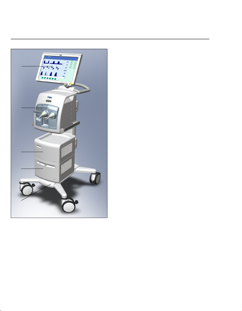
Infinity Acute Care System – Workstation Neonatal Care
How to use the Workstation Neonatal Care
The Workstation Neonatal Care can consist of the
following units:
– Infinity C500 (Medical Cockpit)
– Babylog VN500 (ventilation unit)
– Trolley 2 - 90 cm (trolley)
– GS500 (gas supply unit)
– PS500 (power supply unit)
– Transport Supply Unit (transport supply unit)
Before using the Workstation Neonatal Care, carefully read the following Instructions for Use:
– Instructions for Use for "Workstation Critical
Care and Workstation Neonatal Care"
– Instructions for Use for "Infinity Medical Cock-
pits"
– Instructions for Use for "Babylog VN500"
– Instructions for Use for "Transport Supply Unit"
The Workstation Neonatal Care may include additional accessories, see separate list of accessories.
A Infinity C500 – control and display unit (Medical
Cockpit). Strictly follow the Instructions for Use
for "Infinity Medical Cockpits".
B Babylog VN500 – ventilation unit
C GS500 – gas supply unit
D PS500 – power supply unit
E Trolley 2 - 90 cm
18
Instructions for Use Infinity Acute Care System – Babylog VN500 SW 2.n
001
Page 19
Babylog VN500
A
B
C
E
F
D
G
H
J
I
System Overview
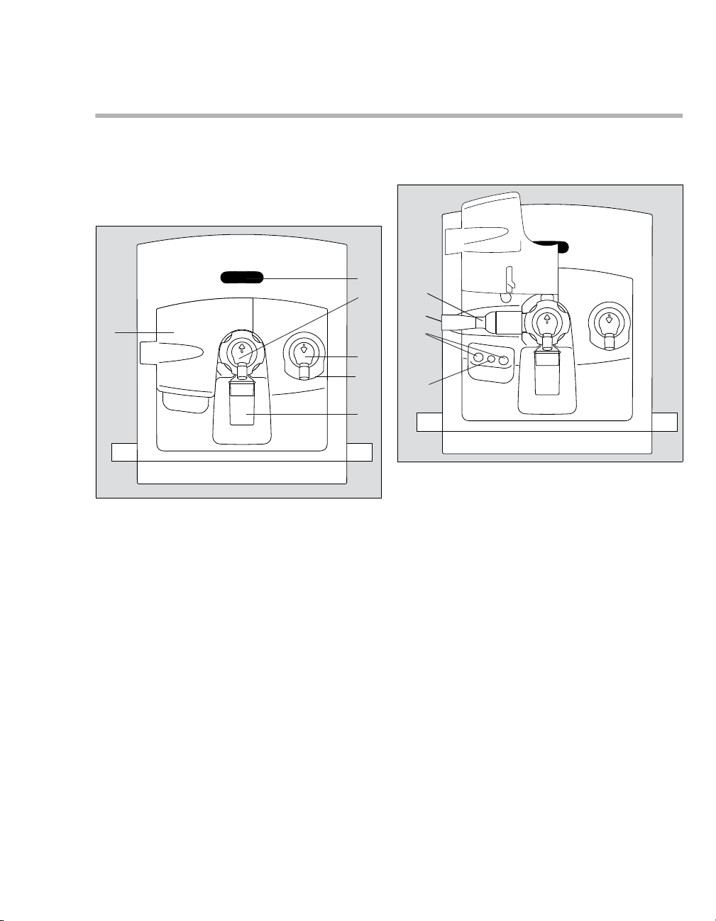
Front
Front, flap closed
A Operation display of ventilation
During ventilation, the inspiratory and expiratory phases are indicated by a bar display. The
measured values for minute volume MV and the
inspiratory O
played.
B Infinity ID neonatal expiratory valve with
expiratory port Exp. (GAS RETURN)
C Inspiratory unit (safety valve with inspiratory
port) Insp. (GAS OUTPUT)
D Gas inlet for the safety valve Emergency air
intake, non-tapered connection (EMERGENCY
AIR INTAKE), do not obstruct
E Water trap
F Flap
2 concentration FiO2 are also dis-
Front, flap folded upwards
G Silencer
070
H Gas outlet Exhaust, non-tapered connection
(EXHAUST – NOT FOR SPIROMETER)
I Connections for future extensions
J Nebulizer port (nebulizer gas outlet for pneu-
matic medication nebulizer)
071
Instructions for Use Infinity Acute Care System – Babylog VN500 SW 2.n 19
Page 20
System Overview
A
B
F
E
G
D
C
A
B
D
E
G
C
F
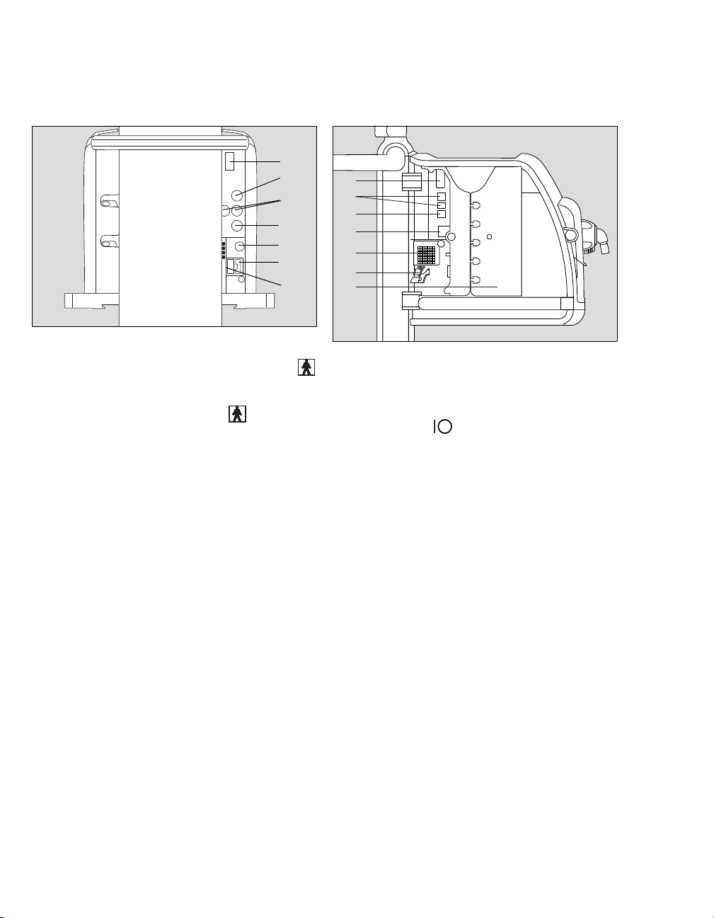
Rear
A Fuse for the internal battery
B Connection for the neonatal flow sensor V5
C Connections for future extensions V6, V8
D Connection for CO
E Potential equalization pin
F Fuse for mains power supply F1, F2
G Connection for mains power supply
2 sensor V7
Left side
004
005
A Connection for system cable to Infinity C500 V1
B Connections for future extensions V2, V3
C Connection for nurse call V4
D Toggle switch
E Ambient air filter with cover
F Strain relief for cable
G Left device flap
20
Instructions for Use Infinity Acute Care System – Babylog VN500 SW 2.n
Page 21
System Overview
C
D
E
B
A
A
B
F
H
D
C
G
E
D
Right side
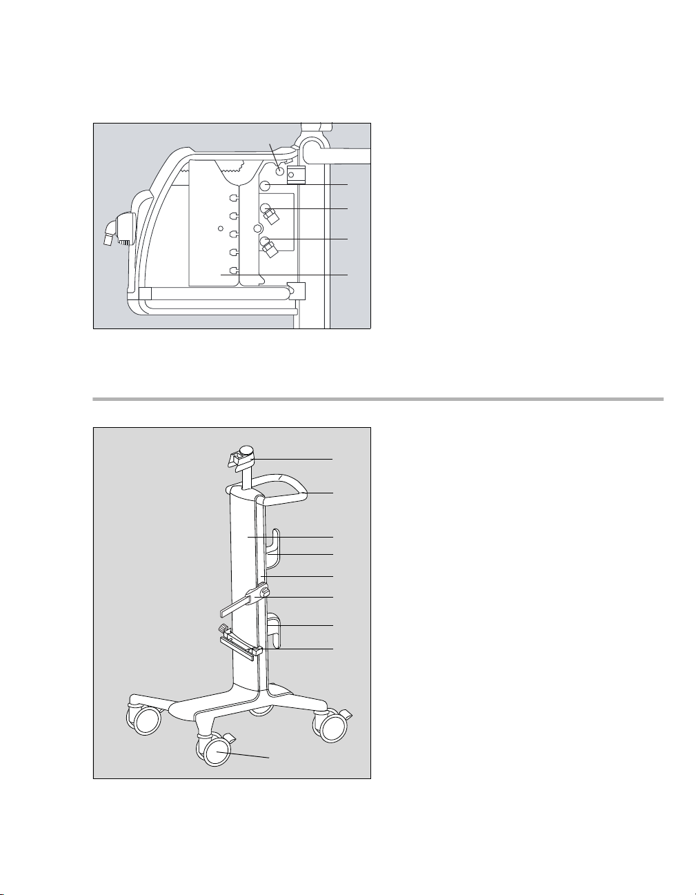
Trolley 2 - 90 cm
A Connection for data cable to the gas supply unit
GS500 V9
B Connection for gas connection to the gas
supply unit GS500
C Connection for Air compressed gas hose Air
(FRESH GAS)
D Connection for O
(FRESH GAS)
E Right device flap
014
A Holder for Infinity C500
B Handle
C Trolley column
D Hose hooks
E Alignment aid
F Humidifier holder, can be swiveled
G Universal holder with standard rail
H Double castors with locking brake, set of 4
2 compressed gas hose O2
038
Instructions for Use Infinity Acute Care System – Babylog VN500 SW 2.n 21
Page 22
System Overview
A
B
C
D
A
C
B
E
F
G
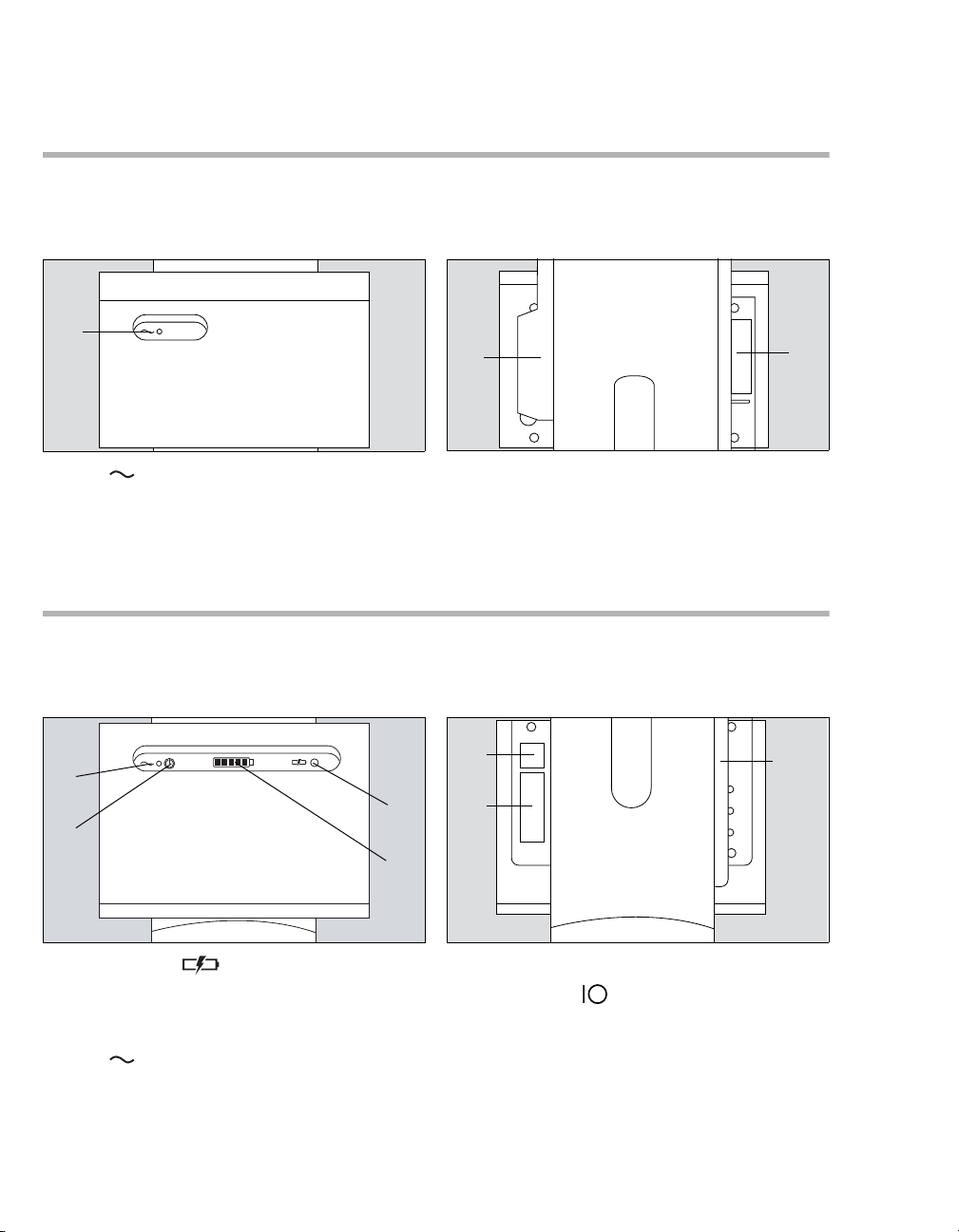
Gas supply unit GS500
Front
A LED for display of mains power supply
Power supply unit PS500
Front
Rear
333
B Rating plate
C Gas connection
Rear
330
A Fault indicator
B Charge indicator
C Standby key
D LED for display of mains power supply
22
Instructions for Use Infinity Acute Care System – Babylog VN500 SW 2.n
332
E Cable duct
F Toggle switch of the power supply unit
G Rating plate
331
Page 23

Range of functions
System Overview
The functions described correspond to the overall
functionality of Babylog VN500. Some functions
are only optional and may not be included in the
individual device configuration. Optional functions
are shown in the separate list of accessories.
Ventilation functions of Babylog VN500
Ventilation modes:
– Pressure-controlled ventilation:
– PC-CMV
–PC-AC
–PC-SIMV
–PC-PSV
–PC-APRV
– PC-HFO
–PC-MMV
– Support of spontaneous breathing:
– SPN-CPAP/PS
– SPN-CPAP/VS
–SPN-PPS
Additional settings for ventilation:
– Apnea Ventilation
– Flow trigger
–Sigh
– Volume Guarantee
–ATC
– AutoRelease
–HFO-Sigh
– Volume Guarantee (HFO)
Special procedures:
– Suction maneuver
– Manual inspiration/hold
– Medication nebulization
Therapy types:
– Invasive ventilation (Tube)
2 Therapy
–O
– Non-invasive ventilation (NIV)
Additional information
For a detailed description of the ventilation modes
and the additional settings see page 236. Abbreviations see page 25.
Monitoring
Patient monitoring is supported by the following
alarm limit settings:
– Maximum airway pressure Paw
– Expiratory minute volume MV
– Apnea alarm time Tapn
– Respiratory rate RR
– End-expiratory CO
The inspiratory O2 concentration is monitored by
automatically set limits.
Babylog VN500 offers the following displays:
– Curves
– Graphic trends
– Numeric trends
– Loops
– Alarm history
– Logbook
– Numeric parameters
– Preconfigured lists for measured values and set
values
– Customized lists for measured values and set
values
– Smart Pulmonary View
During non-invasive ventilation and O
certain monitoring functions are switched off or can
be switched off.
2 concentration etCO2
2 therapy,
Instructions for Use Infinity Acute Care System – Babylog VN500 SW 2.n 23
Page 24

System Overview
Connections for the breathing hoses
For connection of the breathing hoses, the standard IEC 60601-2-12 stipulates conical inspiratory
ports and expiratory ports as per ISO 5356-1 with
a diameter of 15 mm (0.59 inches) or 22 mm
(0.87 inches). Babylog VN500 has, like
Babylog 8000, conical inspiratory ports and expiratory ports with a diameter of 11 mm (0.43 inches).
Electrical power supply
Babylog VN500 is designed for connection to the
hospital's mains power supply with 100 to 240 V at
50/60 Hz. If the mains power supply fails,
Babylog VN500 switches over (without interruption) to the internal battery in order to ensure that
operation can continue for at least 30 minutes (provided that the battery is fully charged and new).
Power supply unit PS500
The Workstation Neonatal Care may also be
equipped with the external power supply unit
PS500.
PS500 is designed for connection to the hospital's
mains power supply (voltage ranges, see page 51).
If the mains power supply fails, PS500 switches
over (without interruption) to the internal batteries in
order to ensure that the operation of the Workstation Neonatal Care can continue for at least
100 minutes (provided that the batteries are new,
fully charged and ventilation is typical). Battery operation is possible for longer in the absence of the
gas supply unit GS500.
Gas supply
Gas supply unit GS500
The Workstation Neonatal Care may also be
equipped with the external gas supply unit GS500.
GS500 supplies Babylog VN500 with compressed
air.
Data transfer
A variety of interfaces can be used for transferring
data:
– USB port for data export and configuration ex-
change using a USB storage media
– USB port for installation of optional applications
using an SIM card reader with SIM card
– RS 232 port on Infinity C500 for data transfer
with the MEDIBUS protocol
Medication nebulizer
For medication nebulization a pneumatic medication nebulizer can be connected.
Connecting accessories
A humidifier and other approved accessories can
be connected to the lateral rails of Babylog VN500.
In so doing, it must be ensured that the maximum
weight of 4 kg (8.8 lbs) does not exceed a maximum distance of 10 cm (3.9 inches).
For hose holders connected to the lateral rails of
Babylog VN500, the maximum weight of 1 kg
(2.2 lbs) must not exceed a maximum distance of
100 cm (39.4 inches).
The accessories can also be connected to the holders provided on the trolley.
Babylog VN500 features country-specific connections for the gas supply with oxygen and medical
air.
24
Instructions for Use Infinity Acute Care System – Babylog VN500 SW 2.n
Page 25

Abbreviations
System Overview
Abbreviation Explanation
% leak Leakage in percent
% Tplat Plateau time in % to the inspiratory
time (set value)
%MVspon Spontaneous breathing portion of
minute volume in percent
Air Connection for Air compressed gas
hose (FRESH GAS)
ALARM
RESET
Acknowledging an alarm message
that is no longer active ("Reset")
Ampl hf Pressure amplitude for HFO
(set value)
Apnea Vent. Apnea ventilation
APRV Airway Pressure Release
Ventilation
ATC Automatic Tube Compensation,
compensation of the tube
resistance
BF Insulation class Body Floating
BTPS Body Temperature Pressure
Saturated, measured values based
on the condition of the patient’s
lungs, body temperature 37 °C
(98.6 °F), water vapor-saturated
gas, atmospheric pressure
C Compliance
C20/Cdyn Index of the last 20 % of compli-
ance in relation to the dynamic total
compliance
Cdyn Dynamic compliance
2O Measuring unit for pressure
cmH
1cmH
2O = approx. 1 mbar
Compens. Degree of tube compensation
COPD Chronic Obstructive Pulmonary
Disease
Cycles sigh Number of cycles during a sigh
phase (set value)
Abbreviation Explanation
2 Dissociation coefficient for CO2
DCO
with HFO
ΔintPEEP Additional intermittent PEEP for
sigh (set value)
ΔPhf Maximum pressure difference of
amplitude with HFO
ΔPsupp Pressure support relative
(above PEEP) (set value)
E Elastance
EIP End Inspiratory Pressure,
end-inspiratory pressure
EMC Electromagnetic compatibility
Emergency
air intake
Safety air inlet, inspiratory relief
valve (EMERGENCY AIR INTAKE)
ESD Electrostatic Discharge
ET Endotracheal tube
2 End-expiratory CO2 concentration
etCO
ETSI European Telecommunications
Standards Institute, European
Telecommunications Standards
Institute
Exhaust Gas outlet (EXHAUST – NOT FOR
SPIROMETER)
Exp. Label on the device, Expiratory port
(GAS RETURN)
Exp. Expiration
Exp. term. Termination criterion in % from the
peak expiratory flow
FCC Federal Communications
Commission, approval authority
for communications devices in
the U.S.
fhf Frequency of oscillation for HFO
(set value)
2 Inspiratory O2 concentration
FiO
(set value)
Instructions for Use Infinity Acute Care System – Babylog VN500 SW 2.n 25
Page 26

System Overview
Abbreviation Explanation
Flow Flow (set value)
Flow Assist Flow support in SPN-PPS
(set value)
Flow trigger Trigger threshold, sensitivity
(set value)
Flowsigh Flow of sighs for HFO
FRC Functional Residual Capacity
GS500 Gas supply unit
HF High frequency
HFO High Frequency Oscillation
HME Heat Moisture Exchanger
hPa Hectopascal, measuring unit for
pressure
1hPa = 1mbar = approx. 1cmH
2O
I:E Ratio of inspiratory time to
expiratory time
I:Ehf I:E for HFO (set value)
I:Espon I:E during spontaneous breathing
IEC/CEI Alarm tone as per IEC 60601-1-8
Insp. Label on the device, Inspiratory
port (GAS OUTPUT)
Insp. Inspiration
Insp. flow Inspiratory flow
Interval sigh Time interval between two sigh
phases (set value)
LAN Local Area Network
MAPhf Mean airway pressure for HFO
(set value)
mbar Millibar, measuring unit for
pressure 1 mbar = approx.
2O
1cmH
MEDIBUS Dräger communication protocol for
medical devices
mmHg Measuring unit for end-expiratory
2 concentration
CO
More... Show more alarms
MRI Magnetic resonance imaging
Abbreviation Explanation
MV Overall minute volume
MV high Upper alarm limit for minute volume
MV low Lower alarm limit for minute volume
MVleak Leakage minute volume
MVmand Mandatory portion of minute
volume
MVspon Spontaneous breathing portion of
minute volume
Neo. Neonates patient category
NIV Non-Invasive Ventilation
NMI Nuclear magnetic imaging
NMR Nuclear magnetic resonance
NTPD Normal Temperature Pressure Dry,
20 °C (68 °F), 1013 hPa, dry
2 Connection for O2 compressed gas
O
hose (FRESH GAS)
2 suction Suction maneuver
O
Palv Alveolar pressure
Paw Airway pressure
Paw high Upper alarm limit for airway
pressure
PC-AC Pressure Control-Assist Control,
assisted-controlled, pressurecontrolled ventilation with back-up
respiratory rate
PC-APRV Pressure Control-Airway Pressure
Release Ventilation, spontaneous
breathing under continuous
positive airway pressure with brief
pressure releases
PC-CMV Pressure Control-Continuous
Mandatory Ventilation, continuous
pressure-controlled ventilation
PC-HFO Pressure Control-High Frequency
Oscillation, pressure-controlled
ventilation with high-frequency
oscillation
26
Instructions for Use Infinity Acute Care System – Babylog VN500 SW 2.n
Page 27

System Overview
Abbreviation Explanation
PC-MMV Pressure Control-Mandatory
Minute Volume Ventilation,
pressure-controlled ventilation to
ensure a mandatory volume per
minute
PC-PSV Pressure Control-Pressure
Support Ventilation, spontaneous
breathing at continuous positive
pressure level with pressure
support and back-up respiratory
rate
PC-SIMV Pressure Control-Synchronized
Intermittent Mandatory Ventilation,
intermittent, triggered, pressurecontrolled ventilation
Ped. pat. Pediatric patient category
PEEP Positive end-expiratory pressure
Phigh Upper pressure level in APRV
(set value)
Pinsp Inspiratory pressure (set value)
PIP Peak Inspiratory Pressure
Plow Lower pressure level in APRV
(set value)
PmanInsp Pressure of the mandatory breath
for the manual inspiration during
NIV (patient category Neo.,
ventilation mode SPN-CPAP)
Pmax Maximum allowed airway pressure
(set value)
Pmax/Paw
high autoset
Linking the maximum airway
pressure to the alarm limit Paw
high
Pmean Mean airway pressure
Pmin Minimum airway pressure
Pplat Airway pressure on the plateau
PS Pressure Support
PS500 Power supply unit
Psigh Inspiratory pressure of sigh for
HFO (set value)
Psupp Pressure support absolute
Abbreviation Explanation
Ptrach Pressure in the trachea
R Resistance (resistance)
r² Correlation coefficient for the
calculation method "Least Mean
Square" for R, C and Τau
REF Material and revision number of the
medical device
RFID Radio Frequency Identification
RR Respiratory rate (set value)
RRapn Respiratory rate of apnea
ventilation (set value)
RRmand Mandatory portion of respiratory
rate
RRsigh Respiratory rate of sighs for HFO
(set value)
RRspon Spontaneous breathing portion of
respiratory rate
RSB Rapid Shallow Breathing, quotient
of spontaneous respiratory rate
and tidal volume
SIM Subscriber Identity Module,
participant identification
Slope Pressure rise time (set value)
Slopesigh Pressure rise time of sighs for HFO
Smart
Pulmonary
Graphic display of lung
characteristics
View
SN Device serial number
SPN-CPAP Spontaneous-Continuous Positive
Airway Pressure, spontaneous
breathing with continuous positive
pressure level
SPNCPAP/PS
Spontaneous-Continuous Positive
Airway Pressure/Pressure
Support, spontaneous breathing
with continuous positive pressure
level with or without pressure
support
Instructions for Use Infinity Acute Care System – Babylog VN500 SW 2.n 27
Page 28

System Overview
Abbreviation Explanation
SPNCPAP/VS
Spontaneous-Continuous Positive
Airway Pressure/Volume Support,
spontaneous breathing with
continuous positive pressure level
with or without volume support
SPN-PPS Spontaneous-Proportional
Pressure Support, spontaneous
breathing with flow-proportional
and volume-proportional pressure
support
2 Partial O2 saturation
SpO
Tapn Apnea alarm time (set value)
Τau Time constant tau
Tdisconnect Time for disconnection alarm
(set value)
Te Expiratory time (set value)
Thigh Time of upper pressure level in
APRV (set value)
Ti Inspiratory time (set value)
Timax Maximum inspiratory time for flow
during pressure or volume support
(set value)
Tisigh Inspiratory time of sigh for HFO
(set value)
Tispon Inspiratory time of sigh for
spontaneous breathing
Tisupp Inspiratory time during pressure
support
Tlow Time of lower pressure level in
APRV
Tlow max Maximum expiratory time during
APRV (set value)
TmanInsp Duration of the breath for the
manual inspiration during NIV
(Neo. patient category, SPN-CPAP
ventilation mode)
Tplat Time of inspiratory plateau
Trach. Tracheostomy tube
Tube Ø Inside diameter of tube (set value)
Abbreviation Explanation
UIP Upper Inflection Point
UMDNS Universal Medical Device
Nomenclature System,
nomenclature for medical devices
N Rated voltage
U
USB Universal Serial Bus, serial bus
system
VG Volume Guarantee
VG (HF) Volume Guarantee for HFO
Vol. Assist Volume support in SPN-PPS
(set value)
VS Volume Support
VT Tidal Volume
VTapn Tidal volume of apnea ventilation
(set value)
VTe Expiratory tidal volume
VTemand Expiratory tidal volume during a
mandatory breath
VTespon Expiratory tidal volume during a
spontaneous breath
VThf Tidal volume for HFO (set value for
VG (HF))
VTi Inspiratory tidal volume
VTimand Inspiratory tidal volume during a
mandatory breath
VTispon Inspiratory tidal volume during a
spontaneous breath
VTmand Tidal volume during a mandatory
breath
VTspon Tidal volume during a spontaneous
breath
WOB Work of Breathing
28
Instructions for Use Infinity Acute Care System – Babylog VN500 SW 2.n
Page 29
Symbols
123
123
123
Audio
paused
System Overview
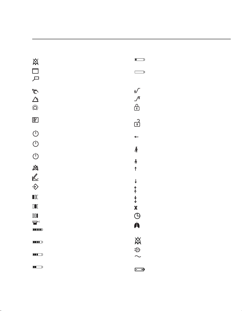
Symbol Explanation
Temporarily suppress acoustic alarm
Group Views, screen displays
Group Trends/Data, information on the
course of ventilation
Group Special procedures
Group Alarms
Group Therapy, ventilation parameter
settings
Group configuration, system settings
and settings for sensors
Group Start/Standby
System on or off (at the key on
Infinity C500)
Switching the power supply unit on or off
(at the key on PS500)
Alarm limit off
Configure trends
Save screen display
View 1
View 2
View 3
Medication nebulizer
Charge state of internal batteries
(Babylog VN500, PS500) 90 to 100 %
Charge state of internal batteries
(Babylog VN500, PS500) 60 to <90 %
Charge state of internal batteries
(Babylog VN500, PS500) 40 to <60 %
Charge state of internal batteries
(Babylog VN500, PS500) 20 to <40 %
Symbol Explanation
Charge state of internal batteries
(Babylog VN500, PS500) <20 %
Internal batteries (Babylog VN500,
PS500) defective or no information
available on their charge state
Lower alarm limit
Upper alarm limit
Setting or access locked
Expiratory valve locked
Setting or access unlocked
Expiratory valve unlocked
Exhaust
Gas outlet (EXHAUST – NOT FOR
SPIROMETER)
Patient category pediatric patients (Ped.
pat.)
Neonates patient category (Neo.)
Display additional information or open
Help
Hide additional information or close Help
Scroll in tables or lists
Scroll in tables or lists
Close dialog window
Active test in the device check
Spontaneous breathing activity by the
patient
Suppress acoustic alarm for 2 minutes
Mains power supply (AC voltage)
PS500, GS500: Mains power supply
(AC voltage)
Power supply from the internal battery of
Babylog VN500
Instructions for Use Infinity Acute Care System – Babylog VN500 SW 2.n 29
Page 30
System Overview
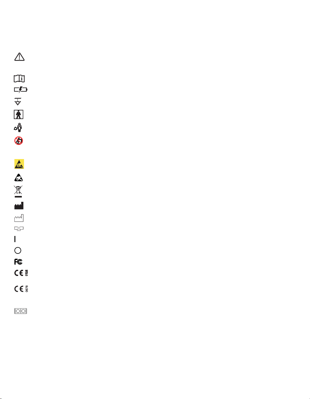
Symbol Explanation
Caution: Observe important safety
information and precautions in the
Instructions for Use.
Observe the Instructions for Use
PS500: Failure, fault
Connection for equipotential bonding
Application part type BF
Nurse call
Marking point on the trolley – do not
lean, press, push or pull against the
trolley above the marking points
ESD warning symbol
ESD warning symbol
Information on disposal
Manufacturer
2009
Manufacturing date
Connection for the neonatal flow sensor
Device ready to switch on
Device switched off
Labeling for FCC approval
Labeling in accordance with Directive
93/42/EEC concerning medical products
Labeling in accordance with Directive
1999/5/EC on radio equipment and telecommunications terminal equipment
Serial interface (on Infinity C500)
Additional symbols on Infinity C500 (Medical
Cockpit) that are not described in these Instructions
for Use are described in the Instructions for Use for
"Infinity Medical Cockpits".
30
Instructions for Use Infinity Acute Care System – Babylog VN500 SW 2.n
Page 31

Operating Concept
Operating concept for Infinity C500 . . . . . . . 32
Operating concept for Babylog VN500. . . . . 32
Main screen . . . . . . . . . . . . . . . . . . . . . . . . . . . 32
Main menu bar . . . . . . . . . . . . . . . . . . . . . . . . . 33
Dialog windows. . . . . . . . . . . . . . . . . . . . . . . . . 34
Therapy bar . . . . . . . . . . . . . . . . . . . . . . . . . . . 34
Therapy controls. . . . . . . . . . . . . . . . . . . . . . . . 34
Setting ventilation parameters . . . . . . . . . . . . . 34
Exceeding the set limit of a ventilation
parameter . . . . . . . . . . . . . . . . . . . . . . . . . . . . . 35
Direct setting of ventilation parameters
(QuickSet). . . . . . . . . . . . . . . . . . . . . . . . . . . . . 35
Linked setting of ventilation parameters . . . . . . 35
Operating Concept
Instructions for Use Infinity Acute Care System – Babylog VN500 SW 2.n 31
Page 32

Operating Concept
123
A
B
C
D
Operating concept for Infinity C500
Infinity C500 is the central operating and display
unit. The general operating concept is described in
the Instructions for Use for "Infinity Medical
Cockpits".
Operating concept for Babylog VN500
The following operating concept only contains the
specific information and operating steps for
Babylog VN500.
This chapter describes:
– Main screen
– Main menu bar
– Dialog windows
– Therapy bar
– Therapy controls
– Setting ventilation parameters
– Exceeding the set limit of a ventilation
parameter
– Direct setting of ventilation parameters
(QuickSet)
– Linked setting of ventilation parameters
Main screen
The main screen displays the most important ventilation information at a glance.
A Header bar with the following fields:
– Patient category, see page 60
– System data, e.g., state of charge of the in-
ternal battery, see page 106
– Therapy status: Therapy type (ventilation or
O2 Therapy), ventilation mode and additional settings
– Alarms, messages and instructions for the
user, see page 112
– Alarm status
B Monitoring area with curves, loops, trends and
measured values, see page 85. The display
can be configured, see page 144.
C Main menu bar with buttons for opening dialog
windows and activating functions, see page 33.
D Therapy bar with the therapy controls for the
ventilation parameters of the active ventilation
mode, see page 34.
32
078
Instructions for Use Infinity Acute Care System – Babylog VN500 SW 2.n
Page 33

Operating Concept
A
B
C
D
E
H
G
F
Main menu bar
The main menu bar contains fixed assigned and
configurable buttons. The buttons are assigned to
various groups. Touching a button opens the corresponding dialog window or activates the corresponding function.
Fixed assigned buttons
F Views... for switching to other configured moni-
toring area views, see page 85.
G Trends/Data... for displaying all the measured
and set values, logbook, trends and for exporting data, see page 119.
H Special procedures... for selecting additional
functions, e.g., suction maneuver, see page 90
or medication nebulization, see page 93.
Configurable buttons
Additional buttons for directly accessing functions
or dialogs can be configured. These buttons are
spatially assigned to the corresponding group. See
"Assigning functions to additional buttons"
on page 146.
100
A Alarms... for setting the alarm limits and dis-
playing the alarm logbook and listing all active
alarms, see page 112.
B Ventilation settings... for setting the ventilation
mode and the ventilation parameters,
see page 74.
C Sensors/ Parameters... for calibrating the sen-
sors, see page 128, and for activating or deactivating monitoring, see page 137.
D System setup... for configuring the device
functions, see page 141.
E Start/ Standby... for selecting standby mode or
starting the therapy, see page 102.
Instructions for Use Infinity Acute Care System – Babylog VN500 SW 2.n 33
Page 34

Operating Concept
B
B
B
C
D
E
A
A
B
C
D
A
Ventilation settings
Dialog windows
Dialog windows consist of one or several pages
which are displayed by touching the corresponding
horizontal or vertical tab. Dialog windows contain
elements for operating the device and inform the
user of current settings. Dialog windows can be
opened by touching a button in the main menu bar.
A Dialog window title
B Tab to open a page
C Message field for dialog-specific information
and instructions
D Button for accessing additional information and
the Help function (if available)
E Button for closing the dialog window
Therapy bar
The therapy bar on the main screen contains the
therapy controls for the active ventilation mode.
Therapy controls
The therapy controls (A) are used to set the ventilation parameters.
Therapy controls are contained in the therapy bar of
the active ventilation mode and in the dialog window for the ventilation settings.
171078
Start-up settings
Arrows beside the scales on the screen knobs indicate the start-up values valid when
Babylog VN500 is switched on. These start-up values can be adjusted specifically as required by the
hospital. See "Configuring start-up settings for the
ventilation parameters" on page 153.
Locking mechanism
The therapy controls in the therapy bar can be
locked against the ventilation parameters being
changed by accident. See "Locking of therapy controls in therapy bar" on page 148.
083128
A Name of active ventilation mode
B Message field for specific messages on the ac-
tive ventilation mode
C Button for opening the dialog window for the
ventilation settings of the active ventilation
mode
D Therapy controls
34
Instructions for Use Infinity Acute Care System – Babylog VN500 SW 2.n
Setting ventilation parameters
1 Touch the therapy control. The color turns yel-
low. The unit of the parameter to be adjusted is
displayed in parentheses.
2 Turn the rotary knob to set the value.
Page 35

Operating Concept
B A
C
D
Ventilation settings
3 Press the rotary knob to confirm the value. The
color of the therapy control turns dark green.
The following chapters of the Instructions for Use
provide a simplified explanation of these steps:
"Use the rotary knob to set and confirm the value."
Exceeding the set limit of a ventilation parameter
When a set limit of a parameter has been reached,
Babylog VN500 displays a message.
z Press the rotary knob to exceed the set limit.
The set limit can be exceeded.
If the maximum set limit for a parameter has been
reached, e.g., depending on other parameters, it is
not possible to exceed the set limit.
z Press the rotary knob. Babylog VN500 adopts
the maximum possible set value.
Direct setting of ventilation parameters (QuickSet)
The therapy control changes to dark green with a
yellow edge. The direct setting function is now active.
087085
3 Press and hold the rotary knob and turn to set
the value.
The set value is immediately effective.
Exceeding the set limit of a parameter with direct setting
When a set limit of a parameter has been reached,
Babylog VN500 displays a message.
4 Release rotary knob for a short moment.
5 Press the rotary knob again and turn it.
The set limit can be exceeded.
When a ventilation parameter is set directly, the
changes to a setting become immediately effective
for the patient. The user can immediately see the
effect the changed setting has on the patient. The
finally chosen setting does not have to be confirmed again.
Ventilation parameters can be set directly in all ventilation modes and can be carried out in the dialog
window for the ventilation settings. Direct settings
are only possible in the therapy bar when the therapy controls are not locked.
O
Setting ventilation parameters directly
1 Touch the corresponding therapy control.
2 Press and hold the rotary knob for approx.
Instructions for Use Infinity Acute Care System – Babylog VN500 SW 2.n 35
2 and Flow cannot be set directly.
3 seconds.
Linked setting of ventilation parameters
The linked setting is possible for PEEP/Pinsp and
for RR/Ti.
Linking PEEP/Pinsp
1 Touch the therapy control PEEP (A) or
Pinsp (B); the color turns to yellow.
The Link (C) button is displayed.
2 Touch the Link (C) button.
Page 36

Operating Concept
The therapy control of the other linked parameter to
be linked (Pinsp or PEEP) turns yellow.
3 Turn the rotary knob to set the value for PEEP
or Pinsp. The other value is also automatically
changed so that the difference in pressure remains constant.
4 Press the rotary knob to confirm the value.
Both therapy controls turn dark green.
Linking RR/Ti
Setting RR and Ti is effected analogously to the
linked setting of PEEP or Pinsp. The I:E ratio re-
mains constant. If the respiratory rate is increased,
the inspiratory time is reduced. If the inspiratory
time is increased, the respiratory rate is reduced.
Additional information
If a condition is reached in which a parameter cannot be changed anymore when setting linked parameters, Babylog VN500 displays a corresponding message in the message field (D).
36
Instructions for Use Infinity Acute Care System – Babylog VN500 SW 2.n
Page 37

Preparation
Safety information on preparation . . . . . . . . 38
Preparing Trolley 2 - 90 cm . . . . . . . . . . . . . . 38
Safety information on the trolley. . . . . . . . . . . . 38
Connecting the universal holder with
standard rail to the trolley . . . . . . . . . . . . . . . . . 39
Connecting the humidifier holder to the
trolley . . . . . . . . . . . . . . . . . . . . . . . . . . . . . . . . 39
Securing accessories to the standard rail. . . . . 39
Securing the compressed air cylinders to
the trolley . . . . . . . . . . . . . . . . . . . . . . . . . . . . . 40
Preparing Infinity C500 . . . . . . . . . . . . . . . . . 41
Positioning Infinity C500. . . . . . . . . . . . . . . . . . 41
Adjusting the position of Infinity C500 . . . . . . . 41
Connecting system cables . . . . . . . . . . . . . . . . 41
Using the MEDIBUS protocol . . . . . . . . . . . . . . 43
LAN and USB interfaces of Infinity C500 . . . . . 43
Preparation
Preparing Babylog VN500 . . . . . . . . . . . . . . . 44
Preparing the Infinity ID neonatal expiratory
valve . . . . . . . . . . . . . . . . . . . . . . . . . . . . . . . . . 44
Safety information for the use of HMEs,
bacterial filters and breathing circuits . . . . . . . . 45
Preparing the breathing gas humidifier. . . . . . . 46
Attaching breathing hoses . . . . . . . . . . . . . . . . 47
Installing a neonatal flow sensor . . . . . . . . . . . 48
Replacing the neonatal flow sensor insert . . . . 49
Installing a CO
Connecting the electrical mains power
supply . . . . . . . . . . . . . . . . . . . . . . . . . . . . . . . . 50
Power supply unit PS500 . . . . . . . . . . . . . . . . . 51
Failure of the electrical power supply . . . . . . . . 52
Power supply of the gas supply unit GS500. . . 52
Connecting the gas supply . . . . . . . . . . . . . . . . 52
Connecting the nurse call . . . . . . . . . . . . . . . . . 53
Closing the flaps at the side of the device . . . . 54
Transportation of patients within the
hospital . . . . . . . . . . . . . . . . . . . . . . . . . . . . . . 54
Instructions for Use Infinity Acute Care System – Babylog VN500 SW 2.n 37
2 cuvette and CO2 sensor. . . . . 49
Page 38

Preparation
Safety information on preparation
WARNING
Before each use, reprocess the device and all
accessories in accordance with the Instructions for Use, see "Reprocessing list"
on page 202. Note the hospital hygiene regulations!
WARNING
The device must not be tilted more than 10°!
Failure to observe this may result in the device toppling over. Danger of damage to device or personal injury!
WARNING
Securely mount Babylog VN500. Check for se-
cure fit. Danger of damage to device or personal injury!
Preparing Trolley 2 - 90 cm
WARNI NG
Do not place any containers with liquid on or
above the device! Penetrating liquid may impair the correct functioning of the device or
damage the device and endanger the patient!
WARNI NG
Failure to observe the permitted maximum
load and weight distribution may result in the
device toppling over. Danger of damage to device or personal injury! Observe the permitted
maximum load and weight distribution, see
"Maximum load" on page 228.
CAUTION
When parking the device, lock all the double castors of the trolley and check that the brakes are
working properly.
Safety information on the trolley
WARNING
Do not use the trolley in the event of visible
damage, e.g., damaged double castors! Contact DrägerService.
WARNING
Do not lean, press, push or pull against the
trolley above the marking points on the trolley.
The trolley could topple over.
38
Instructions for Use Infinity Acute Care System – Babylog VN500 SW 2.n
CAUTION
Connect all devices securely to the trolley. Check
for secure fit. Danger of damage to device or personal injury!
Page 39

Preparation
A
B
C
Front of the trolley
B
C
D
A
Front of the
trolley
Connecting the universal holder with standard rail to the trolley
Attach the universal holder with standard rail to the
front of the trolley.
1 Unscrew the adjusting screw (A) completely.
2 Attach the right-hand side of the universal hold-
er to the right-hand side of the rail (B). Make
sure that the catch of the universal holder is
completely behind the alignment aid.
3 Align the universal holder (C) horizontally and
press the left-hand side of the universal holder
onto the left-hand side of the column.
4 Tighten the adjusting screw (A). Make sure that
the catch of the universal holder is completely
behind the alignment aid.
5 Check that the universal holder is fixed
securely.
Connecting the humidifier holder to the trolley
The humidifier holder is attached to the front of the
trolley. The humidifier holder can be fastened on
the left or right-hand side of the trolley column. The
attachment of the humidifier holder on the righthand side is shown.
049
192
1 Hold the humidifier holder at the desired height
on the guide (A) of the trolley column.
2 Turn the clamping screw (B) to the left until the
base (C) fits into the guide of the trolley column.
3 Turn the clamping screw (B) to the right until the
humidifier holder is secured firmly in the guide.
4 Move the standard rail (D) to the desired posi-
tion.
Securing accessories to the standard rail
Adjusting the height of the universal holder
1 Unscrew the adjusting screw (A).
2 Adjust the height of the universal holder (C).
3 Align the universal holder horizontally.
4 Retighten the adjusting screw (A).
Instructions for Use Infinity Acute Care System – Babylog VN500 SW 2.n 39
Secure the accessories, e.g., breathing gas humidifier or medication nebulizer, to the standard rail.
Observe the maximum load! See chapter Technical
Data, "Maximum load" on page 228.
Page 40

Preparation
A
A
A
A
B
B
Securing the compressed air cylinders to the trolley
Only available with the option cylinder holder
WARNING
Attach the compressed air cylinders using
both Velcro fasteners securely to the trolley.
Otherwise there is a risk of the trolley toppling
over. Danger of damage to device or personal
injury!
WARNING
Have the height of the upper holder adjusted
to the respective compressed air cylinders by
trained service personnel. The height must be
adjusted so that the top half of the compressed air cylinders are secured by the Velcro strip. Otherwise there is a risk of the trolley toppling over. Danger of damage to device
or personal injury!
WARNING
The length of the Velcro fasteners must match
the diameter of the compressed air cylinders
to ensure that the Velcro fasteners can hold
the cylinders securely. Have an appropriate
Velcro strip fitted by trained service personnel
if necessary. This is essential to ensure that
the compressed air cylinders are properly secured.
CAUTION
Not every combination of compressed air cylinder
diameter and length can be secured. When used
in combination with a pressure reducer, the compressed air cylinder must not come into contact
with the console of the trolley. The maximum diameter is 176 mm (6.93 inches) when the base of
the compressed air cylinder is resting completely
on the base plate of the lower holder or is semispherical in shape.
1 Place the cylinders into the mountings on the
trolley.
2 Secure each cylinder with 2 Velcro fasteners
(A).
3 Secure the compressed gas hoses by hanging
them over the hose hooks (B).
Compressed air cylinders with the following dimensions can be secured:
Diameter: 80 to 176 mm (3.15 to 6.93 inches)
Length: 420 to 760 mm (16.54 to 29.92 inches)
40
Instructions for Use Infinity Acute Care System – Babylog VN500 SW 2.n
193
CAUTION
Position the compressed air cylinders fitted with
pressure reducers in such a way to prevent the
pressure reducers from being damaged during
transport. The lower part of the trolley is designed
to protect against collisions. Take particular care
when the compressed air cylinders being used
are too large.
Page 41

Preparing Infinity C500
B
C
A
A
Preparation
Positioning Infinity C500
Infinity C500 is suitable for positioning on the trolley
or on a standard rail.
Positioning Infinity C500 on the trolley
1 Hook the Infinity C500 holder (A) into the
mounting (B) on the trolley.
2 Tighten the locking screw (C).
3 Make sure that Infinity C500 is securely at-
tached to the trolley.
Positioning Infinity C500 on a standard rail
When Infinity C500 is connected to the trolley:
1 Unscrew the locking screw (C).
2 Lift Infinity C500 out of the mounting (B) on the
trolley.
3 Hook Infinity C500 into the standard rail.
4 Tighten the locking screw.
5 Make sure that Infinity C500 is securely at-
tached to the standard rail.
Adjusting the position of Infinity C500
Tilting the position of Infinity C500
Infinity C500 can be tilted down and up.
1 Press and hold the tilt release button (A).
010
2 Tilt Infinity C500 to the desired working position.
3 Release the button and make sure that it en-
gages securely.
Turning Infinity C500
Infinity C500 can be turned by a maximum of 180°
to the left or 90° to the right.
z Turn to the desired working position.
Connecting system cables
The system cable is connected to Infinity C500 and
to Babylog VN500. The system cable is fixed in a
clamp.
011
Instructions for Use Infinity Acute Care System – Babylog VN500 SW 2.n 41
Page 42

Preparation
A
B
C
F
D
E
G
H
Connecting the system cable to Infinity C500
1 Unscrew the cover from the socket (A).
2 Insert the system cable connector (B) into the
socket (A). Ensure that the connector is inserted with the correct orientation.
3 Screw the cover back on.
Connecting the system cable to Babylog VN500
1 Open the flap on the left-hand side of
Babylog VN500.
2 Route the system cable between
Babylog VN500 and the handle.
4 Insert the system cable connector (E) into the
socket until the connector audibly clicks into
place.
5 Insert the protective sleeve (C) into the protec-
tive plate (F) at the same time.
6 Turn the protective sleeve (C) by approx. 90°
until the protective sleeve clicks into place. The
cable is secured.
7 Close the left-hand flap.
Disconnecting the system cable from Babylog VN500
018003
1 Push the locking mechanism on the connector
(E) backwards and pull out the connector.
2 Turn the protective sleeve (C) by approx. 90°
and pull it out of the protective plate (F).
Fixing the system cable in the clamp (G)
3 Clip the protective sleeve (C) immediately after
the connector (E) onto the system cable (D).
Align the protective sleeve so that the slots of
the protective sleeve are facing downwards and
upwards.
42
Instructions for Use Infinity Acute Care System – Babylog VN500 SW 2.n
188
1 Open the clamp cover (H).
2 Place the system cable into the clamp. Keep the
cable length short between the clamp and
Babylog VN500.
3 Close the clamp cover (H) and engage. Ensure
that the cover engages securely.
Removing the system cable from the clamp
1 Open the clamp cover.
2 Remove the cable from the clamp.
3 Close the clamp cover and engage.
Page 43

Preparation
A
A
BB
Using the MEDIBUS protocol
NOTE
All transferred data is for information only and
should not be used as basis for diagnostic or therapeutic decisions.
MEDIBUS is a software protocol for the transfer of
data between Babylog VN500 and an external
medical or non-medical device (e.g., patient monitors or computers for data management systems).
The combination of Babylog VN500, Infinity C500
and the external device must comply with the requirements of Directives IEC/EN 60601-1-1 and
IEC/EN 60601-1-2.
Additional information
"MEDIBUS for Evita Infinity V500 and
Babylog VN500" (9039527)
"Dräger RS MEDIBUS Protocol Definition"
(9028258)
Connecting an external device for using MEDIBUS
Configuring the interface
A description is given in chapter "Configure interfaces" on page 163.
LAN and USB interfaces of Infinity C500
Use of LAN interfaces (A) of Infinity C500 is only
permitted for service purposes.
The USB interfaces (B) should only be used for
connecting a USB storage media or a USB SIM
card reader.
WARNING
Do not simultaneously touch the connectors
of the interfaces and the patient. Danger of
electrical shock.
007
z Connect an external device to the interface
COM 1, COM 2 or COM 3 (A) of
Infinity C500. Use MEDIBUS cable 8416326.
Instructions for Use Infinity Acute Care System – Babylog VN500 SW 2.n 43
195
Page 44

Preparation
A
B
C
D
Preparing Babylog VN500
Preparing the Infinity ID neonatal expiratory valve
WARNING
Only use properly reprocessed expiratory
valves which have been sufficiently dried.
Otherwise the proper functioning of the device may be impaired and the patient endangered.
The expiratory valve is mounted and then inserted
into the ventilation unit.
Mounting the expiratory valve
1 Fit the diaphragm (A) onto the edge of the expi-
ratory valve housing. Make sure that the diaphragm is fitted properly.
2 If the silencer (B) has been removed, fit the si-
lencer.
040006
3 Fit the collection container for the water trap
(C).
Open the flap
Open the flap (D) before inserting the expiratory
valve.
329
z Lift the flap (D) by the lower edge and pivot it up-
wards.
44
Instructions for Use Infinity Acute Care System – Babylog VN500 SW 2.n
Page 45

Preparation
E
D
Insert the expiratory valve into the ventilation unit
1 Turn the locking ring (E) as far as possible to the
left.
2 Push the expiratory valve into the fitting.
3 Turn the locking ring (E) as far as it will go to the
right until it clicks audibly into place.
4 Check that it is properly secured by gently pull-
ing on the expiratory valve.
Close the flap
When the expiratory valve and the silencer are fitted, tilt the flap (D) downwards.
Leave the flap closed during ventilation.
Safety information for the use of HMEs, bacterial filters and breathing circuits
CAUTION
Additional components in the breathing circuit
such as bacterial filters or HME increase the dead
space and result in the increase of compliance or
resistance. The use of additional components
therefore requires particular care and monitoring!
Additional components in the breathing circuit can
increase the inspiratory and expiratory breathing
resistance and exceed standard requirements.
Examples: Inspiratory and expiratory bacterial filters, HMEs.
073006
Babylog VN500 is designed to minimize the patient's work of breathing. Operation does therefore
not require inspiratory or expiratory bacterial filters.
The use of bacterial filters or HMEs requires particular care and monitoring by the user. Especially
during medication nebulization and humidification,
the resistance of the expiratory bacterial filter may
increase gradually.
A higher breathing resistance leads to a greater
work of breathing and trigger effort. Under unfavorable conditions, this can lead to an undesirable intrinsic PEEP, which can be recognized by the fact
that the expiratory flow does not return to "baseline"
at the end of expiration. If the PEEP is unacceptably high, this is indicated by an alarm. The measured PEEP is then more than 4 mbar (4 cmH
above the set PEEP. If the end-expiratory flow is
high, the alarm threshold increases to a measured
PEEP value of up to 12 mbar (12 cmH
A breathing resistance in the patient connection
cannot be monitored directly by Babylog VN500.
For this reason:
z Before starting ventilation, determine in standby
mode inspiratory and expiratory breathing resistance in the breathing circuit by means of the
breathing circuit check.
z Check the condition of the patient and the de-
vice's measured values for volume and resistance more frequently.
2O).
2O)
Instructions for Use Infinity Acute Care System – Babylog VN500 SW 2.n 45
Page 46

Preparation
A
D
C
B
z Observe the Instructions for Use for the HMEs,
bacterial filters and breathing circuits in use.
Preparing the breathing gas humidifier
z Prepare the Fisher & Paykel MR 850 breathing
gas humidifier in accordance with the corresponding Instructions for Use.
CAUTION
Do not use an HME together with a breathing gas
humidifier! This can lead to an increased breathing resistance.
Connecting the Fisher & Paykel MR 850 breathing gas humidifier
The breathing gas humidifier can be connected in
the following ways:
– on the standard rail of the universal holder
– on the humidifier holder of the trolley
– on the humidifier holder on the side rail
Connecting the breathing gas humidifier on the universal holder with standard rail
Connecting the breathing gas humidifier to the humidifier holder of the trolley
185194
z Connect the breathing gas humidifier to the hu-
midifier holder of the trolley.
z Tilt the breathing gas humidifier into the correct
position.
Connecting the breathing gas humidifier to the humidifier holder on the side rail
If a compressor is used on the trolley, use humidifier holder on the side rail. The holder can be connected to the left-hand or right-hand side of device.
z Clamp the breathing gas humidifier to the stan-
dard rail (A) under the ventilation unit and screw
firmly into place.
46
Instructions for Use Infinity Acute Care System – Babylog VN500 SW 2.n
1 Hook the holder on the lateral standard rail (B)
030
of Babylog VN500. Position the holder on the
standard rail so that the flap at the side of the
unit can still be opened.
2 Turn the clamping screw (C) until the holder is
fixed securely on the rail.
3 Attach the breathing gas humidifier to the mount
(D).
Page 47

Preparation
D
E
B
C
A
Additional information
For the order numbers of the holder for the breathing gas humidifier, see the list of accessories.
Attaching breathing hoses
WARNING
Do not use antistatic or conductive breathing
hoses. The use of these materials increases
the danger of electric shock to the patient and
of fire in an oxygen-enriched environment.
CAUTION
The sterile packaging of disposable articles
should only be opened immediately before use.
Otherwise there is a risk of infection.
1 Hang the hinged arm (A) on the lateral standard
rail of Babylog VN500 and tighten the screws.
Depending on the desired position of the device
in relation to the bed, the hinged arm can be fitted to either side of Babylog VN500.
CAUTION
Do not reverse the connections for inspiration (B)
and expiration (C). Humidification is ineffective if
the connections are reversed.
3 Turn the inspiratory port and the expiratory port
in the direction of hoses.
A water trap is required for the
Fisher & Paykel MR 850 breathing gas humidifier
depending on the breathing circuit used.
4 If a water trap is required, install the water trap
(D) in a vertical position.
5 Connect the Y-piece (E) to the breathing hoses.
6 Insert the Y-piece or the breathing hoses in the
opening of the hinged arm.
Using the Infinity ID breathing circuit
Babylog VN500 recognizes the use of an Infinity ID
breathing circuit. The message Infinity ID Breath-
ing Circuit detected is displayed in the header bar.
The following Infinity ID functions are supported:
– Detection of reversed hoses
– Detection of non-compliance with the patient
category
– Automatic configuration of breathing circuit and
humidifier
These functions are only supported in standby
mode.
z Fit the Infinity ID breathing hoses in standby
mode.
Setting the breathing circuit
Babylog VN500 supports the user in selecting the
breathing circuit on the page Start/Standby > Br.
2 Connect breathing hoses to the inspiratory port
(B) and to the expiratory port (C).
circuit/ Humidifier.
057
z Set the breathing circuit according to the patient
category.
Instructions for Use Infinity Acute Care System – Babylog VN500 SW 2.n 47
Page 48

Preparation
B
A
C
D
E
F
G
Whenever the breathing hoses or the breathing gas humidifier have been changed
z Check the breathing circuit, see "Performing the
breathing circuit check" on page 66.
Additional information
For the order numbers of the breathing circuits and
the hinged arm, see the list of accessories.
Installing a neonatal flow sensor
The following neonatal flow sensors are available:
– Neonatal flow sensor ISO 15 (8411130)
– Neonatal flow sensor Y-piece (8410185)
Installing an ISO 15 neonatal flow sensor (8411130)
Installing a neonatal flow sensor Y-piece (8410185)
301302
1 Connect Y-piece with integrated neonatal flow
sensor (D) to the breathing hoses.
2 Connect plug (E) of the flow sensor cable to the
flow sensor.
Further procedure for both neonatal flow sensors
3 Position patient connector of the Y-piece
about 45° downwards to prevent condensation
from forming on the neonatal flow sensor.
4 Route the cables along the breathing hoses to
the device.
1 Insert the neonatal flow sensor (A) into the pa-
tient connector of the Y-piece (B).
2 Connect plug (C) of the flow sensor cable to the
flow sensor.
48
Instructions for Use Infinity Acute Care System – Babylog VN500 SW 2.n
300
5 Insert the connector (F) of the flow sensor cable
into the socket (G) at the rear of
Babylog VN500.
Page 49

Additional information
A
B
C
D
A
B
D
C
For the order numbers of the neonatal flow sensor,
see the list of accessories.
Replacing the neonatal flow sensor insert
Preparation
If the Babylog VN500 displays the alarm message
Neonatal flow sensor?, the insert of the neonatal
flow sensor must be replaced.
1 Disconnect the flow sensor cable (A) from the
neonatal flow sensor.
2 Press the buttons (B) on both sides while pulling
the insert (C) out of its housing.
3 Push in new insert (C) until it engages. The two
markings (D) must line up.
4 Connect plug (A) of the flow sensor cable to the
neonatal flow sensor.
5 Calibrate the neonatal flow sensor,
see page 129.
Installing a CO2 cuvette and CO2 sensor
1 Insert the cuvette (A) into the patient connector
of the Y-piece. The cuvette windows are facing
to the side.
2 Fit the CO
is facing towards the device.
303
3 Insert the connector of the CO
the socket (D) at the rear of Babylog VN500.
4 Selecting the cuvette type, see page 131.
2 sensor (B) on the cuvette. The cable
2 sensor (C) into
054180
For small premature infants, do not carry out CO2
measurements because the CO
cantly increases the dead space.
2 cuvette signifi-
Additional information
"Calibrating the CO
For the order numbers of the accessories for the
CO
2 application, see the list of accessories.
2 sensor" on page 131.
Instructions for Use Infinity Acute Care System – Babylog VN500 SW 2.n 49
Page 50

Preparation
A
B
D
F
C
E
O
I
G
H
Connecting the electrical mains power supply
If the power supply unit PS500 is connected, see
"Power supply unit PS500" on page 51.
Connecting the electrical mains power supply to Babylog VN500
The mains power must conform with the voltage
range specified on the rating plate (100 V to 240 V,
50/60 Hz).
1 Plug the appliance socket (A) onto the appli-
ance connector (B).
2 Position the power cable (C) in the clamp (D).
Fit the clamp into the housing (E). Tighten the
screw (F) (stress relief).
Checking the toggle switch on Babylog VN500
CAUTION
Do not press the toggle switch during ventilation.
Prerequisite: The flap on the left-hand side of the
device is opened.
182
z Check whether the toggle switch (G) is set to
(on).
z If the toggle switch is set to (off), set the tog-
gle switch to (on).
WARNI NG
Do not simultaneously touch the connectors
of the interfaces (H) and the patient. Danger of
electrical shock.
002186
Electricity supply from the internal battery
Babylog VN500 is provided with an internal battery
to ensure that operation of the device can continue
for at least 30 minutes (provided that the battery is
fully charged and new) following failure of the
mains power supply.
z Insert the mains plug into the mains power
socket.
The LED on Infinity C500 lights up green.
50
Instructions for Use Infinity Acute Care System – Babylog VN500 SW 2.n
CAUTION
The internal battery is intended exclusively for
emergency use and not for normal operation! It is
essential to operate the device with mains power
again as soon as possible after switching over to
operation with the internal battery.
Page 51

Additional information
A
For more information on the internal battery, see
"Mains power supply / DC power supply"
on page 105.
If the gas supply unit GS500 is connected, see
"Power supply of the gas supply unit GS500"
on page 52.
Preparation
I
O
Power supply unit PS500
Connecting the electrical mains power supply to PS500
The mains power must conform with the voltage
range specified on the rating plate:
– 100 to 127 V at 50 Hz or 60 Hz
– 220 to 240 V at 50 Hz
– 220 to 240 V at 60 Hz with additional equipoten-
tial bonding
z Insert the mains plug into the mains power
socket.
The LED on PS500 lights up green.
Checking the toggle switch on PS500
CAUTION
Do not press the toggle switch during ventilation.
z Check whether the toggle switch (A) is set to
(on).
z If the toggle switch is set to (off), set the tog-
gle switch to (on).
z Check the toggle switch on Babylog VN500,
see "Checking the toggle switch on
Babylog VN500" on page 50
Electrical power supply from the internal batteries
PS500 is provided with internal batteries to ensure,
following failure of the mains power supply, that the
operation of the Workstation Neonatal Care can
continue for at least 100 minutes (provided the batteries are fully charged and new and ventilation is
typical).
CAUTION
The internal batteries are intended exclusively for
emergency use and not for normal operation! It is
337
essential to operate the device with mains power
again as soon as possible after switching over to
operation with the internal batteries.
For more information on the power supply unit, see PS500
See "Power supply unit PS500" on page 107.
335
Instructions for Use Infinity Acute Care System – Babylog VN500 SW 2.n 51
Page 52

Preparation
A
B
C
C
Failure of the electrical power supply
If the power supply fails and the internal batteries of
Babylog VN500 and PS500 are fully discharged,
then Babylog VN500 generates a power failure
alarm. The ventilation settings and the alarm limits
remain saved even in the event of a mains power
failure.
Power supply of the gas supply unit GS500
If Babylog VN500 is equipped with the power supply unit PS500, then the gas supply unit is supplied
with power using the power supply unit.
If Babylog VN500 is not equipped with the power
supply unit PS500:
z Plug the mains plug of the gas supply unit into
the mains socket.
The LED on GS500 lights up green.
Connecting the gas supply
WARNING
Do not bring any oxygen supply components
into contact with oil and grease. Danger of explosion through spontaneous ignition!
WARNING
Only use compressed gases approved for
medical use. The compressed gases must be
free of dust and oil particles and dry. Otherwise the proper functioning of the device cannot be ensured.
Central gas supply
Prerequisite: The flap on the right-hand side of the
device is opened.
1 Screw the compressed gas hose for air to the
connection Air (A) and the O
hose to the O
Babylog VN500.
2 Plug the connectors into the wall outlets for the
central gas supply.
3 Position the compressed gas hoses over the
hose hooks (C).
The gas delivered through compressed gas hoses
is used as fresh gas (FRESH GAS).
Additional information
For the order numbers of the compressed gas hoses, see the list of accessories.
2 connection (B) of
2 compressed gas
021
52
Gas supply from cylinders
If the central gas supply fails or is not available, the
gas can be supplied from cylinders.
Instructions for Use Infinity Acute Care System – Babylog VN500 SW 2.n
Page 53

Additional information
Brown (COM)
Green (NC)
White (NO)
A
B
Air supply from a gas supply unit (GS500), see
"Gas supply unit GS500" on page 99.
Connecting the nurse call
Preparation
The nurse call is used for transmitting high priority
alarm messages (warning) to a central hospital
alarm system.
Safety information for using the nurse call
CAUTION
A fault in any of the components in the link between the nurse call and the central hospital alarm
system (e.g., in the unit's electronics for nurse
call, in the unit's power supply or in the alarm generator of the central hospital alarm system) may
result in failure of the nurse call.
CAUTION
Connection of a nurse call does not relieve staff of
their duty to check the monitoring on the device
screen at regular intervals. Screen displays must
be checked regularly.
CAUTION
All alarms of Babylog VN500 must be checked
regularly even when the nurse call is connected.
Do not use nurse call as the sole source of alarm
information!
029022
As soon as Babylog VN500 signals an alarm, the
connection between the white cable and the brown
cable (NO and COM) is closed and the nurse call is
activated.
Connecting the nurse call to the ventilation unit
Prerequisite: The flap on the left-hand side of the
device is opened.
Connecting the nurse call to the central alarm
z The nurse call cable must be connected to the
lead to the central alarm station in the hospital
by trained service personnel.
1 Plug the nurse call connector (A) into the socket
(B) until it engages audibly.
NOTE
The connector must engage audibly into the socket to ensure all alarm messages are transmitted
properly.
2 Check the correct operation of connected nurse
Instructions for Use Infinity Acute Care System – Babylog VN500 SW 2.n 53
call system.
Page 54

Preparation
Information on the nurse call
High priority alarm messages (warning) are transmitted to a central alarm station in the hospital. Medium priority (caution) and low priority (note) alarm
Closing the flaps at the side of the device
z Close the lateral flaps of the device after prepa-
ration.
messages are not transmitted.
The nurse call is also activated when the internal
acoustic alarm generator in the device is defective.
If, in the event of an alarm, the Audio paused
key is pressed, the acoustic alarm on the device
and the nurse call are suppressed for 2 minutes.
Additional information
For the order number of the nurse call cable, see
the list of accessories.
CAUTION
Keep both lateral flaps on the device closed during operation to prevent accidental actuation of
the toggle switch or connections becoming loose.
Transportation of patients within the hospital
023
WARNING
The device must not be tilted more than 10°!
Failure to observe this may result in the device toppling over. Danger of damage to device or personal injury!
WARNING
The device must not be placed on the bed
while transferring a patient within the hospital.
The device could topple over or fall down.
Danger of damage to device or personal injury!
WARNING
Do not lean, press, push or pull against the
trolley above the marking points on the trolley.
The trolley could topple over.
54
Instructions for Use Infinity Acute Care System – Babylog VN500 SW 2.n
WARNI NG
Do not move trolley faster than at a walking
pace. There is an increased danger of the trolley toppling over at thresholds, uneven surfaces and ramps. Reduce the speed of transport further. Danger of damage to equipment!
WARNI NG
Two people are always required to move the
device. Otherwise there is an increased risk of
the device toppling over.
WARNI NG
Make sure to securely hold onto the handle of
the trolley whenever moving or positioning
the device. Otherwise there is an increased
risk of the device toppling over.
Page 55

Preparation
A
WARNING
Patient hazard due to discharged batteries.
Only start transporting patients when the batteries are sufficiently charged.
When transporting patients within the hospital,
medical staff must ensure that the patient is monitored continuously.
Using Babylog VN500 with a safety bar
CAUTION
During the transportation of patients within the
hospital, Babylog VN500 must be used with a
safety bar (A) in order to prevent accidental disconnection of the breathing hoses or damage to
the inspiratory port and the expiratory port.
Additional information
Air supply from the gas supply unit GS500, see
"Gas supply unit GS500" on page 99.
Power supply from the power supply unit PS500,
see "Power supply unit PS500" on page 107.
For the order number of the safety bar, see the list
of accessories.
020
Increase the toppling stability during the transportation of patients within the hospital
To ensure that the equipment cannot topple over,
the accessories must be moved to the most advantageous position:
1 Hinged arm set to minimum deflection.
2 Hoses and cables hooked as close as possible
to the trolley.
3 Humidifier secured to the trolley, not to the lat-
eral rails of Babylog VN500.
Instructions for Use Infinity Acute Care System – Babylog VN500 SW 2.n 55
Page 56

This page intentionally left blank
56 Instructions for Use Infinity Acute Care System – Babylog VN500 SW 2.n
Page 57

Getting Started
Safety information on getting started. . . . . . 58
Prerequisites to getting started. . . . . . . . . . . . . 58
Switching on Babylog VN500 and
Infinity C500 . . . . . . . . . . . . . . . . . . . . . . . . . . 58
Select patient . . . . . . . . . . . . . . . . . . . . . . . . . 59
Using the settings of the previous patient. . . . . 59
Admission of a new patient. . . . . . . . . . . . . . . . 59
Selecting the breathing circuit and the
breathing gas humidifier . . . . . . . . . . . . . . . . 62
Check readiness for operation . . . . . . . . . . . 63
Safety information on the system check. . . . . . 63
Starting the system check. . . . . . . . . . . . . . . . . 63
Performing a device check . . . . . . . . . . . . . . . . 63
Performing the breathing circuit check . . . . . . . 66
Getting Started
Selecting Tube or NIV application mode . . . 68
Setting parameters for the tube . . . . . . . . . . . . 68
Select therapy type. . . . . . . . . . . . . . . . . . . . . 69
Start therapy . . . . . . . . . . . . . . . . . . . . . . . . . . 70
Displaying the status of accessories . . . . . . 71
Instructions for Use Infinity Acute Care System – Babylog VN500 SW 2.n 57
Page 58

Getting Started
A
B
C
D
Start
Safety information on getting started
WARNING
Ventilation does not take place in standby
mode! The device must only be set to standby
mode when no patient is connected to the device. Other settings may jeopardize the patient!
CAUTION
Before using for the first time, the device must remain connected to the mains power supply for at
least 4 hours so that the internal battery can be
fully charged.
CAUTION
Before using the power supply unit PS500 for the
first time, the device must remain connected to
the mains power supply for at least 8 hours so that
the internal batteries can be fully charged.
CAUTION
Condensation may form when the device is
moved from a cold storage location to a warm environment. Do not switch on the device as otherwise its proper functioning may be adversely affected. Wait until the condensation has dried.
Prerequisites to getting started
– Babylog VN500, Infinity C500, PS500 and
GS500 are reprocessed and assembled ready
for operation.
– The electrical power supply and the gas supply
must be connected.
– The toggle switches Babylog VN500 and
PS500 are set to (on).
Switching on Babylog VN500 and Infinity C500
z Press the (A) button on Infinity C500.
The system is started. The Start dialog is displayed.
58
Babylog VN500 provides you with two options:
– Use settings of previous patient (B)
– Admit new patient (C)
017
If the Start dialog is closed via the X (D) button,
Instructions for Use Infinity Acute Care System – Babylog VN500 SW 2.n
Babylog VN500 adopts the settings of the previous
patient.
116
Page 59

If a data loss occurs, the previous settings cannot
A
Start
B
CC
D
Start/Standby
be recovered. The Current patient (B) button is not
displayed.
Select patient
Getting Started
Using the settings of the previous patient
Prerequisite: The Start dialog is opened.
z Touch the Current patient (A) button.
The last used patient-related settings including the
alarm limits, application mode and device status
are restored.
The Start/Standby (B) page is displayed.
Babylog VN500 is in standby mode.
The button for starting the therapy (D) is preset for
15 seconds. When the therapy is started, the settings become effective.
Admission of a new patient
For a new patient, Babylog VN500 determines the
ventilation parameters’ start-up settings based on
the patient category (factory setting) or the body
weight. The factory settings for the settings dependent on patient category and weight can be
changed in the System setup dialog window.
116092
The patient category or the body weight can only be
changed when a new patient is admitted. In the patient category Ped. pat., the body height is entered
and from that the ideal body weight is determined.
In the Neo. patient category, the body weight is entered directly. The weight-dependent setting for a
new patient is only possible after selecting Weight
in the System setup dialog window.
The alarm limit start-up settings are recalculated
according to the customized system configuration.
When a new patient is admitted, the settings and
trend data of the previous patient are deleted.
Babylog VN500 displays the ventilation parameter
start-up settings (C).
Instructions for Use Infinity Acute Care System – Babylog VN500 SW 2.n 59
Page 60

Getting Started
A
B
Start
125
D
E
F
C
Start/Standby
G
F
C
Start/Standby
H
Prerequisite: The Start dialog is opened.
1 Touch the following button for a new patient:
– New Ped. pat. (A) for new pediatric patients
– New Neo. (B) for new neonatal patients
The respective button turns yellow.
2 Confirm with the rotary knob.
The Start/Standby page is displayed.
Babylog VN500 is in standby mode.
Ventilation parameter start-up settings by patient category
The Start/Standby page (C) contains the buttons
for the patient category:
The ventilation parameters displayed in the lower
part of the page (F) are the start-up settings for the
selected patient category.
Determining the start-up settings can take up to
5 seconds. No entries can be made during this
time.
Ventilation parameter start-up settings by body height/body weight
116
Prerequisite: In the System setup dialog window,
the Weight function was configured and a new patient was admitted.
In the Ped. pat. patient category, the
Start/Standby page (C) contains the button for
body height (G) and the field for the ideal body
weight (H).
New Ped. pat. (D)
New Neo. (E)
1 Touch the button for the desired patient
category (D) or (E).
2 Confirm with the rotary knob.
60
106
1 Touch the button for the body height (G).
2 Set the body height by turning the rotary knob
and push to confirm.
Babylog VN500 determines the start-up values for
VT, RR, Slope and Flow trigger based on the ideal
body weight calculated from the body height. The
values for VT and RR are displayed in the lower
part of the page (F). The other ventilation parameters displayed in the lower part of the page are startup settings for the selected patient category.
In the Neo. patient category, the patient’s body
weight is set directly. The Start/Standby page (C)
contains the button for this start-up body weight (I).
Instructions for Use Infinity Acute Care System – Babylog VN500 SW 2.n
Page 61

1 Touch the button for the start-up body weight (I).
F
I
J
C
Start/Standby
2 Using the rotary knob, set the start-up body
weight and confirm the value.
The button for the current body weight (J) is displayed. After the patient has been admitted, the
current body weight corresponds to the start-up
body weight. If the current body weight is different
from the start-up body weight:
3 Touch the button for the current body weight (J).
4 Using the rotary knob, set the current body
weight and confirm the value.
Babylog VN500 determines the start-up values for
VT, RR, Slope and Flow trigger based on the
start-up body weight. The values for VT and RR are
displayed in the lower part of the page (F). The other ventilation parameters displayed in the lower part
of the page are start-up settings for the selected patient category.
By setting the current body weight, it is possible to
display the measured values relative to the body
weight, e.g., VT/kg BW.
Determining the start-up settings can take up to
3 seconds. No entries can be made during this
time.
Getting Started
Additional information
The configuration for the ventilation parameter
start-up values by body height/body weight or by
patient category is entered on the System setup >
Ventilation > Start settings page. See chapter
"Configuring start-up settings for the ventilation parameters" on page 153.
For information on configuring customized alarm
limits, see chapter "Setting start-up values for alarm
limits" on page 149.
319
For information on starting the therapy, see "Start
therapy" on page 70.
Whenever the patient category has been changed
Check the breathing circuit, see "Performing the
breathing circuit check" on page 66.
Instructions for Use Infinity Acute Care System – Babylog VN500 SW 2.n 61
Page 62

Getting Started
A
B
C
D
E
Start/Standby
Selecting the breathing circuit and the breathing gas humidifier
The breathing circuit and the breathing gas
humidifier can only be selected in standby mode.
1 Touch the Start/ Standby... button in the main
menu bar.
2 Touch the Br. circuit/ Humidifier (A) tab.
The page for selecting the breathing circuit and the
breathing gas humidifier is displayed.
Selecting the breathing circuit from the selection list
3 Touch the (B) button.
4 Select the breathing circuit used from the selec-
tion list.
5 Confirm with the rotary knob.
To help with the selection, the selected breathing
circuit is displayed as a detailed representation (C)
and also described as text (D).
Babylog VN500 automatically selects the corresponding humidification type based on the breathing circuit (E) selected. Some breathing circuits
provide the selection of HME/Filter and None.
If the breathing circuit used is not included in the selection list
1 Touch the (B) button.
2 Select Other from the selection list.
3 Confirm with the rotary knob.
4 Select the humidification type (E):
– Active humid., exp. unheated
– Active humid., exp. heated
– HME/Filter
–None
Press the corresponding button.
Infinity ID Breathing circuits
When using Infinity ID breathing circuits, the connected hose type as well as the corresponding humidification type are set automatically.
If the message Infinity ID Breathing Circuit de-
080
tected is not displayed when connecting an
Infinity ID breathing circuit, then use a different
Infinity ID breathing circuit. If the message is still
not displayed, replace the Infinity ID neonatal expiratory valve or inspiratory valve.
Whenever the breathing circuit or the breathing gas humidifier have been changed:
z Check the breathing circuit, see "Performing the
breathing circuit check" on page 66.
62
Instructions for Use Infinity Acute Care System – Babylog VN500 SW 2.n
Page 63

Check readiness for operation
A
Start/Standby
B
C
B
D
A
Start/Standby
Getting Started
The system check consists of the device and
breathing circuit check.
Safety information on the system check
WARNING
The device must not be put into operation if a
fault is discovered during the device and
breathing circuit check! Patient hazard!
CAUTION
The device and breathing circuit check must be
carried out before use on the patient in order to
confirm that Babylog VN500 is operating correctly.
Starting the system check
The system check is only possible in standby
mode.
1 Touch the Start/ Standby... button in the main
menu bar.
2 Touch the System check (A) tab.
Performing a device check
The device check is only possible in standby mode.
Keep test lung ready
Pediatric test lung (8409742) for the pediatric and
neonatal breathing circuit
The test lung must only be inserted into the patient
connector of the Y-piece after instruction by
Babylog VN500.
Starting the device check
Prerequisite: The System check (A) page is
opened.
1 Touch the Device check (B) tab.
Babylog VN500 displays the individual test steps in
a list (C). The size of the list depends on the available applications.
2 Touch the Start (D) button.
3 Confirm with the rotary knob.
Babylog VN500 displays the date, time and results
of the last system check on the Overview (B) page.
Instructions for Use Infinity Acute Care System – Babylog VN500 SW 2.n 63
101
102
Page 64

Getting Started
G
F
E
Start/Standby
H
J
I
Test steps in the device check
In the device check the following test steps are carried out:
– Auxiliary acoustical alarm (test of auxiliary
alarm/power failure alarm)
– Breathing circuit connection (visual inspection
of breathing circuit)
– Inspect humidifier (visual inspection of breath-
ing gas humidifier)
2 sensor calibration
–CO
– Neonatal flow sensor: Calibration
– Neonatal flow sensor: Measurement
– Test lung connection
– Gas supply sensors: Calibration
2 supply
–O
– Air supply
– GS500 (gas supply unit) (if the gas supply unit
function is activated)
– Pressure sensor calibration valve
– Expiratory valve (expiratory valve check)
– Safety valve (safety function check)
2 sensor: Calibration
–O
– Medication nebulizer (medication nebulizer
control check)
Device check procedure
Babylog VN500 guides the user in the form of a
question/answer dialog through the respective test
step. The instruction field (E) displays the questions
or instructions how to carry out the test steps.
The questions must be answered by pressing the
Yes (F) or No (G) buttons.
The Next test (H) button can be used to skip the
test steps.
A test step is also skipped if the necessary prerequisites have not been met.
102
The test steps in the device check are displayed with the following symbols:
Rotating symbol : Active test step
Green dot : Correct result
Red dot : Incorrect result
Colorless dot : Test step not carried out
Repeating test steps in the device check
1 Touch the Repeat (I) button.
2 Confirm with the rotary knob.
All test steps that have not yet been carried out or
that were unsuccessful are repeated.
Aborting the device check
1 Touch the Cancel (J) button.
2 Confirm with the rotary knob.
The device check is also aborted when the Device
check page is exited. The device check can be
continued when the Device check page is called
again.
1 Touch the Repeat (I) button.
2 Confirm with the rotary knob.
64
Instructions for Use Infinity Acute Care System – Babylog VN500 SW 2.n
Page 65

Getting Started
Test results
The test results obtained from the device check and
the calibration and zero-checking values of the sensors remain stored until the next calibration, even if
the device is switched off.
Incorrect test steps and remedies
Errors in the following safety-relevant test steps
generate the medium-priority alarm message
Device check failed:
– Pressure sensor calibration valve
– Expiratory valve
– Safety valve
The alarm cannot be acknowledged. Do not start
ventilation!
Errors in non-safety-relevant test steps or test steps
that are not carried out on account of a prerequisite
generate the low-priority alarm message Device
check incomplete.
The alarm causes and their remedies are displayed
on the Current alarms page.
The following table shows the remedies for eliminating the errors during the device check:
Test step Remedy
Auxiliary acoustical
Contact DrägerService.
alarm
CO
2 sensor
calibration
Check whether the
2 sensor is connected.
CO
Wait for the CO2 sensor to
complete its three-minute
warm-up phase.
Check whether the
2 sensor or the cuvette
CO
are soiled.
Neonatal flow
sensor: Calibration
Clean the flow sensor.
Keep flow sensor sealed
during calibration.
Check whether the flow
sensor cable is connected.
Test step Remedy
GS500 (gas supply
unit)
Check whether the gas
connection to the device is
kinked.
Check whether the data cable is connected.Contact
DrägerService.
Gas supply sensors:
Calibration
Check whether the compressed gas hoses are connected.
2 supply Check whether the O2 com-
O
pressed gas hose is connected.
Air supply Check whether the Air com-
pressed gas hose is connected.
Pressure sensor
calibration valve
Connect the test lung.
Check the breathing circuit
for leaks.
Check whether the compressed gas hoses are connected.
Check whether the expiratory valve is properly engaged.
Expiratory valve Check whether the water
trap is connected.
Check whether the expiratory valve is properly engaged.
Safety valve Connect the test lung.
Check the breathing circuit
for leaks.
Check whether the compressed gas hoses are connected.
Check whether the expiratory valve is properly engaged.
2 sensor:
O
Calibration
Check whether the compressed gas hoses are connected.
Instructions for Use Infinity Acute Care System – Babylog VN500 SW 2.n 65
Page 66

Getting Started
Test step Remedy
Medication
nebulizer
Check whether the
compressed gas hoses are
connected.
z Eliminate the causes of the error and repeat the
test step.
z If the test step is still incorrect, contact
DrägerService.
Inspiratory calibration
Inspiratory calibration takes approx. 2 minutes.
This test step must be carried out every 3 months.
The test step can be skipped with No and is displayed as "successfully completed" (green dot).
If the test step is skipped with Next test, the test
step is displayed as "not carried out" (colorless dot).
If a complete calibration is necessary after
3 months and the test step is skipped with Next
test, the test step is displayed as "failed" (red dot).
Calibrating the O
The O
2 sensor is calibrated during each device
check. The regular calibration of the O
2 sensor
2 sensor en-
sures the specified accuracy.
If the test step is skipped with Next test and the
O2 sensor is not calibrated for 3 months, the accuracy of the O
eter field for FiO
2 sensor will be reduced. In the param-
2 a question mark appears next to
the measured value. After calibration during the device check the sensor will work again with full accuracy. The measured value is displayed in the parameter field.
If the test step is skipped with Next test, the test
step is displayed as "not carried out" (colorless dot).
If Babylog VN500 requires the O
2 sensor to be
calibrated and the test step is still skipped with
Next test, the test step is displayed as incorrect
(red dot).
CAUTION
If the quality of the oxygen from the central gas
supply is not sufficient, calibrate the O
2 sensor
with a corresponding calibration gas (100 % O2).
Otherwise this may result in an incorrect calibration.
After the device check
z Performing the breathing circuit check.
Performing the breathing circuit check
The check is only possible in standby mode.
The breathing circuit check must be performed:
– Device check
– after changing the breathing circuit
– after changing the breathing gas humidifier
– after changing the patient category
Test steps during the breathing circuit check
The following test steps are carried out:
– Leakage
– Compliance
– Insp. Resistance
– Exp. Resistance
66
Instructions for Use Infinity Acute Care System – Babylog VN500 SW 2.n
Page 67

Getting Started
B
A
C
D
E
F
Start/Standby
G
Start/Standby
Starting the breathing circuit check
Prerequisite: The System check (A) page is
opened.
1 Touch the Breathing circ. check (B) tab.
The values of the last test are displayed (C). If a valid measurement has not yet taken place, the standard values are displayed.
2 Touch the Start (D) button.
3 Confirm with the rotary knob.
4 When requested by Babylog VN500 in the in-
struction field (E): seal the Y-piece or the neonatal flow sensor Y-piece, e.g., with a sterile glove.
Confirm with OK (F).
5 When requested, open the Y-piece or remove
the neonatal flow sensor Y-piece. Confirm with
OK (F).
The current leakage flow is displayed continuously
throughout the test. A leakage flow up to
300 mL/min at a pressure of 60 mbar (60 cmH
is permissible.
After the leak test, Babylog VN500 determines the
compliance and the inspiratory and expiratory resistance of the breathing circuit.
When changing the breathing circuit and type of humidifier, Babylog VN500 automatically resets the
values for hose compliance and hose resistance to
default values. When using Infinity ID breathing circuits, the default values of the breathing circuit detected are used. The leakage measurement becomes invalid.
When the patient category is changed, the breathing circuit that was last used in this category is selected and the corresponding values for hose compliance and hose resistance are used.
The leakage measurement becomes invalid when
a new patient is admitted to the same patient category. The values for hose resistance and hose compliance are retained.
It is recommended to perform the breathing circuit
check before commencing patient ventilation with a
newly started device.
Aborting the breathing circuit check
103
1 Touch the Cancel (G) button.
2 Confirm with the rotary knob.
The leakage measurement becomes invalid. The
values for hose resistance and hose compliance
are reset to the default values.
2O)
Repeating the breathing circuit check
If the breathing circuit is changed after the breathing circuit check, the humidification type or the patient category is changed, the breathing circuit
check will have to be repeated.
The breathing circuit check is also necessary when
using Infinity ID breathing circuits.
103
Instructions for Use Infinity Acute Care System – Babylog VN500 SW 2.n 67
Page 68

Getting Started
A
B
C
Start/Standby
A
C
D
Start/Standby
B
Selecting Tube or NIV application mode
Babylog VN500 can change between non-invasive
ventilation and tube ventilation.
The application mode can only be selected in
standby mode.
1 Touch the Start/ Standby... button in the main
menu bar.
2 Touch the Tube/NIV (A) tab.
3 Touch the Tube (B) or NIV (C) button.
4 Confirm with the rotary knob.
Observe the information on changing the application mode!
Setting parameters for the tube
The tube inside diameter and tube type can be entered for the following functions:
– Display of Ptrach, independent of ATC,
– Improvement of leakage compensation
– Measurement of resistance R and
compliance C
When the tube inside diameter and tube type are
entered, the measured value R corresponds with
the patient resistance. When the tube inside diameter and tube type are not entered, the measured
value R corresponds with the total resistance.
Prerequisite: The Tube/NIV (A) page is opened.
The Tube application mode has been selected.
113
CAUTION
Application mode NIV must not be activated with
intubated patients.
WARNING
Alarm limits and ventilation settings must be
checked or set again in order to ensure complete monitoring of ventilation after changing
from NIV application mode to Tube application
mode.
Additional information
For information on using the NIV application mode
for non-invasive ventilation, see "NIV – Non-invasive ventilation" on page 82.
68
Instructions for Use Infinity Acute Care System – Babylog VN500 SW 2.n
113
Activating or deactivating the calculation of tracheal pressure
1 Touch the appropriate button (B).
2 Confirm with the rotary knob.
If ATC is switched off, the calculation of tracheal
pressure is always deactivated when a new patient
is admitted.
Page 69

Getting Started
A
BC
Start/Standby
Selecting the tube type
In the Neo. patient category, this selection is not
available.
1 Touch the appropriate button (C).
2 Confirm with the rotary knob.
Select therapy type
Babylog VN500 can choose between the therapy
types Ventilation and O
The therapy type can only be changed in standby
mode.
1 Touch the Start/ Standby... button in the main
menu bar.
The Start/Standby (A) page is displayed.
2 Therapy.
Entering the inside diameter
1 Touch the (D) button.
2 Set the value by turning the rotary knob and
push to confirm.
126
2 Touch the Ventilation (B) or O
2 Therapy (C)
button.
3 Confirm with the rotary knob.
Additional information
O
2 Therapy, see page 100.
Setting ventilation, see page 74.
Instructions for Use Infinity Acute Care System – Babylog VN500 SW 2.n 69
Page 70

Getting Started
A
B
Start/Standby
C
Start therapy
Before using on the patient
z Carry out a system check to ensure that
Babylog VN500 is operating correctly,
seepage63.
z Check the therapy settings: For information on
setting alarm limits, see page 114. Setting ven-
tilation modes and ventilation parameters, see
"Setting ventilation" on page 74.
Starting ventilation or O
2 therapy
1 Touch the Start/ Standby... button in the main
menu bar.
The Start/Standby (A) page is displayed. The Start
(B) remains preset for 15 seconds.
Additional information
The page for the ventilation settings can be opened
with the Ventilation settings... (C) button.
2 Confirm with the rotary knob.
Babylog VN500 starts the therapy with the set ventilation parameters. The main screen for ventilation
or O
2 therapy is displayed.
When the Start button is no longer preset
After 15 seconds the Start button is no longer preset.
1 Touch the Start (B) button.
2 Confirm with the rotary knob.
70
Instructions for Use Infinity Acute Care System – Babylog VN500 SW 2.n
092
Page 71

Displaying the status of accessories
1 Touch the Start/ Standby... button in the main
menu bar.
2 Touch the Accessory status tab.
Babylog VN500 displays the time until it is recommended to exchange the accessories.
Sterilization of the Infinity ID expiratory valve or inspiratory valve may gradually impair the operation
of RFID transmission. This may mean that
Infinity ID breathing circuit functions may not work
or may no longer work reliably. The status for the
Infinity ID accessories is not displayed.
Additional information
The time for the exchange interval can be configured on the System setup > Exchange intervals
page. See "Exchange intervals" on page 161.
Getting Started
Instructions for Use Infinity Acute Care System – Babylog VN500 SW 2.n 71
Page 72

This page intentionally left blank
72 Instructions for Use Infinity Acute Care System – Babylog VN500 SW 2.n
Page 73

Operation
Operation
Setting ventilation . . . . . . . . . . . . . . . . . . . . . 74
Overview. . . . . . . . . . . . . . . . . . . . . . . . . . . . . . 74
Opening the Ventilation settings dialog window 74
Selecting ventilation modes . . . . . . . . . . . . . . . 74
Setting ventilation parameters . . . . . . . . . . . . . 75
Basic settings for ventilation. . . . . . . . . . . . . . . 76
Additional settings for ventilation . . . . . . . . . . . 79
NIV – Non-invasive ventilation . . . . . . . . . . . 82
Overview. . . . . . . . . . . . . . . . . . . . . . . . . . . . . . 82
Safety information on using NIV. . . . . . . . . . . . 82
Selecting the NIV application mode . . . . . . . . . 82
Starting NIV ventilation . . . . . . . . . . . . . . . . . . . 83
Setting ventilation parameters for NIV . . . . . . . 83
Monitoring during NIV. . . . . . . . . . . . . . . . . . . . 84
Display curves and measured values. . . . . . 85
Overview. . . . . . . . . . . . . . . . . . . . . . . . . . . . . . 85
Changing the screen view . . . . . . . . . . . . . . . . 85
Changing the display of monitoring fields. . . . . 85
Evaluating loops . . . . . . . . . . . . . . . . . . . . . . . . 86
Freeze waveforms . . . . . . . . . . . . . . . . . . . . . . 87
Smart Pulmonary View. . . . . . . . . . . . . . . . . . . 88
Help . . . . . . . . . . . . . . . . . . . . . . . . . . . . . . . . . 89
Fitting the Aeroneb Pro nebulizer . . . . . . . . . . 97
Gas supply unit GS500 . . . . . . . . . . . . . . . . . 99
2 Therapy . . . . . . . . . . . . . . . . . . . . . . . . . . . 100
O
Safety information on O
Preparing O
Switching on O
Setting FiO
Switching off O
2 therapy . . . . . . . . . . . . . . . . . . . 100
2 therapy . . . . . . . . . . . . . . . . . 101
2 and flow for O2 therapy. . . . . . . . 101
2 therapy . . . . . . . . . . . . . . . . . 102
2 therapy . . . . . . . . . . 100
Standby mode . . . . . . . . . . . . . . . . . . . . . . . . 102
Activating standby mode . . . . . . . . . . . . . . . . . 102
Continuing the therapy . . . . . . . . . . . . . . . . . . 103
Ending operation. . . . . . . . . . . . . . . . . . . . . . 103
Storing Babylog VN500. . . . . . . . . . . . . . . . . 104
Mains power supply / DC power supply . . . 105
Power supply unit PS500 . . . . . . . . . . . . . . . 107
Fault – Cause – Remedy on PS500 . . . . . . . . 109
Oxygen enrichment for suction
maneuver. . . . . . . . . . . . . . . . . . . . . . . . . . . . . 90
Overview. . . . . . . . . . . . . . . . . . . . . . . . . . . . . . 90
Before suction. . . . . . . . . . . . . . . . . . . . . . . . . . 90
Automatic interruption of oxygen enrichment . . 91
After reconnection . . . . . . . . . . . . . . . . . . . . . . 91
Manual inspiration – Manual inspiration/hold92
Medication nebulization. . . . . . . . . . . . . . . . . 93
Safety information on medication nebulization . 93
Preparing the pneumatic medication nebulizer 93
Connecting the medication nebulizer to the
breathing circuit . . . . . . . . . . . . . . . . . . . . . . . . 94
Switching on medication nebulization. . . . . . . . 95
Aborting medication nebulization . . . . . . . . . . . 97
Required steps after medication nebulization. . 97
Instructions for Use Infinity Acute Care System – Babylog VN500 SW 2.n 73
Page 74

Operation
123
B
C
A
E
G
D
F
Ventilation settings
B
Ventilation settings
C
A
BBB
Setting ventilation
Overview
This chapter describes how to set ventilation
modes and basic settings as well as additional settings for ventilation parameters.
For a detailed description of the ventilation modes
and ventilation parameters, see chapter "Description of the ventilation modes" on page 236 and "Additional settings for ventilation" on page 249.
Opening the Ventilation settings dialog window
The Ventilation settings dialog window can be
opened as follows:
z Touch the Ventilation settings... button (A) in
the main menu bar.
z Touch the (B) button in the therapy bar.
z Touch the displayed ventilation mode (C) in the
header bar.
The page for the active ventilation mode (D) with
the Basic settings (F) appears by default. The cor-
responding therapy controls (E) are displayed.
The tab for Additional settings (G) can be used to
supplement the active ventilation mode with additional settings.
083083
Selecting ventilation modes
Prerequisite: The Basic settings (A) page is
opened.
Babylog VN500 opens the Ventilation settings dialog window.
74
Instructions for Use Infinity Acute Care System – Babylog VN500 SW 2.n
The Ventilation settings dialog window contains
5 tabs for selecting the ventilation modes. 4 tabs
(B) have ventilation modes permanently assigned
to them. The fifth tab (C) can be used to select another ventilation mode, which can be selected from
the available ventilation modes.
078
The following 4 ventilation modes are preset at the
factory:
– PC-CMV
–PC-AC
–PC-SIMV
– PC-PSV
Page 75

Operation
Ventilation settings
D
C
E
F
Ventilation settings
B
C
D
Ventilation settings
A
E
For information on changing the assignment of ventilation modes, see "Configuring start-up settings
for the ventilation modes" on page 152.
Selecting an additional ventilation mode in the dialog window
1 Touch the Other modes (D) tab.
All the available ventilation modes (E) are displayed.
2 Touch the button for the corresponding ventila-
tion mode. The color of the (D) tab turns yellow.
3 Confirm with the rotary knob.
The additional ventilation mode is displayed in the
fifth tab (C). The ventilation mode is active.
Setting ventilation parameters
Prerequisite: The Basic settings (A) page is
opened.
1 Touch the corresponding therapy control, e.g.,
(B).
170077
2 Set the value by turning the rotary knob and
push to confirm.
The additional ventilation parameters derived from
the ventilation parameter are calculated by
Babylog VN500 and displayed in the setting assistance field (C).
Information is displayed in the message field (D),
e.g., when the setting limit of a parameter has been
reached.
131078
Changing the ventilation mode
1 Touch the corresponding tab, e.g., (F). The col-
2 Preset the ventilation parameters if necessary.
3 Confirm with the rotary knob. The color of the
The ventilation mode is active. The settings are applied to the patient.
Instructions for Use Infinity Acute Care System – Babylog VN500 SW 2.n 75
or of the tab turns yellow.
tab turns dark green.
Setting ventilation parameters in the therapy bar
The ventilation parameters of the active ventilation
mode can also be set with the therapy controls in
the therapy bar (E).
Additional information
"Exceeding the set limit of a ventilation parameter"
on page 35.
"Direct setting of ventilation parameters (QuickSet)" on page 35.
Page 76

Operation
"Linked setting of ventilation parameters"
on page 35.
Basic settings for ventilation
The basic settings of the ventilation parameters are
listed in the following tables:
– Pressure-controlled ventilation modes
– Spontaneous breathing support
WARNING
If flow measurement is deactivated for SPN-
CPAP with the use of a nasopharyngeal tube,
use a separate monitoring device.
CAUTION
Only remove the water trap of the expiratory valve
briefly during ventilation. Otherwise, ventilation
will be impaired.
76
Instructions for Use Infinity Acute Care System – Babylog VN500 SW 2.n
Page 77

Pressure-controlled ventilation modes
Operation
Ventilation
parameters
FiO
2 XXXXXXX
VT X
PC-SIMV PC-AC PC-CMV PC-APRV PC-MMV PC-PSV PC-HFO
1)
1)
X
Ventilation mode
1)
X
XX
1)
Ti X X X X
RR X X X X X
Slope or
Insp. flow
2)
Pmax X
Pinsp X
XXXXXX
3)
4)
3)
X
4)
X
3)
X
4)
X
3)
X
3)
X
3)
X
4)
X
PEEP X X X X X
ΔPsupp X X
Timax X
5)
Thigh X
Tlow X
6)
Phigh X
Plow X
Tlow max X
Exp. term. X
7)
7)
I:Ehf X
fhf X
Ampl hf X
MAPhf X
1) if VG is switched on
2) depending on configuration, Slope adjustment
3) if Pmax/Paw high autoset is activated and ATC or VG is switched on
4) if VG is switched off
5) in the Neo. patient category in the Tube application mode, or in the Ped. pat. patient category in the NIV application mode
6) If AutoRelease is switched off
7) if AutoRelease is switched on
Instructions for Use Infinity Acute Care System – Babylog VN500 SW 2.n 77
Page 78

Operation
Spontaneous breathing support
Ventilation
parameters
2 XXXX
FiO
SPN-CPAP/PS SPN-CPAP/VS SPN-CPAP
Ventilation mode
1)
SPN-PPS
VT X
Timax X
Slope or
Insp. flow
3)
Pmax X
2)
XXX
4)
2)
X
4)
X
2)
X
4)
X
PEEP X X X X
ΔPsupp X
Vol. Assist X
Flow Assist X
TmanInsp X
PmanInsp X
1) only available in the Neo. patient category in the NIV application mode
2) in the NIV application mode or in the Neo. patient category
3) depending on configuration, Slope adjustment
4) if Pmax/Paw high autoset is activated
78
Instructions for Use Infinity Acute Care System – Babylog VN500 SW 2.n
Page 79

Additional settings for ventilation
A
B
Ventilation settings
C
D
Ventilation settings
C
DD
Overview of possible supplementary settings
The ventilation modes can be combined with additional settings to optimize ventilation. The table
shows the possible additional settings for the respective ventilation mode.
Operation
Ventilation
mode
Apnea
Ventilation
Trigger Sigh ATC Volume
Additional settings
Guaran-
tee
Auto
Release
HFO-
Sigh
Vol ume
Guarantee
(HFO)
PC-CMV X X X
PC-AC X XXX
PC-SIMV X X XXX
PC-PSV X X X X
PC-MMV X X X X
PC-APRV X X X
SPN-CPAP/PS X X X
SPN-CPAP/VS X X X
SPN-PPS X X X
PC-HFO XX
Setting the supplementary settings
Prerequisite: The page with the active ventilation
The page for setting the corresponding parameters
is opened.
mode is open.
1 Touch the Additional settings (A) tab.
The additional settings of the active ventilation
mode are displayed.
2 Touch the tab of the respective additional set-
Instructions for Use Infinity Acute Care System – Babylog VN500 SW 2.n 79
ting (B).
3 Use the (C) buttons to activate or deactivate the
additional setting.
4 Touch the corresponding therapy control (D).
084
5 Set the value by turning the rotary knob and
push to confirm.
098
Page 80

Operation
Ventilation parameters of the additional settings
CAUTION
High trigger sensitivity may lead to auto-triggering
of the ventilator.
Additional settings Ventilation parameters Dependencies, information
Apnea Ventilation On/Off
VTapn
RRapn
Pmax If Pmax/Paw high autoset is configured
PEEP In PC-APRV
Flow trigger In PC-APRV
Slope In SPN-PPS
Configuration of the Automatic return from Apnea
Ventilation function, see "Configuring general settings" on page 158. Description, see "Automatic re-
turn from apnea ventilation" on page 249.
Trigger Flow trigger
Sigh On/Off
ΔintPEEP
Interval sigh
Cycles sigh
ATC On/Off See chapter "Configuration" on page 141.
Tube type (ET/Trach.) only available in the Ped. pat. patient category
Tube Ø Inside diameter of tube
Compens. Degree of compensation:
Compens. = 100 % – airway pressure regulation to
the tracheal level
Pmax If Pmax/Paw high autoset is configured
Volume Guarantee On/Off See chapter "Configuration" on page 141
VT
Pmax If Pmax/Paw high autoset is configured
Pinsp If VG is switched off
AutoRelease On/Off
Exp. term.
Tlow If AutoRelease is switched off
Tlow max If AutoRelease is switched on
HFO-Sigh Psigh
RRsigh
Tisigh
Flowsigh If Insp. flow is configured, see page 158
Slopesigh If Slope is configured, see page 158
80
Instructions for Use Infinity Acute Care System – Babylog VN500 SW 2.n
Page 81

Additional settings Ventilation parameters Dependencies, information
Volume Guarantee
(HFO)
On/Off
VThf
Ampl hf Set the amplitude before switching off the Volume
Guarantee (HFO)
Additional information
For a detailed description of the additional settings,
see in chapter "Additional settings for ventilation"
on page 249.
Operation
Instructions for Use Infinity Acute Care System – Babylog VN500 SW 2.n 81
Page 82

Operation
NIV – Non-invasive ventilation
Overview
Babylog VN500 can be used for the ventilation of
intubated patients (application mode Tube) and for
non-invasive ventilation (application mode NIV).
This chapter describes the use of non-invasive ventilation in the NIV application mode.
The following ventilation modes can be selected in
the NIV application mode:
Ventilation mode Patient category
Ped. pat. Neo.
PC-CMV X X
PC-AC X
PC-SIMV X
PC-PSV X
PC-MMV X
PC-APRV X
SPN-CPAP X
SPN-CPAP/PS X
SPN-CPAP/VS X
SPN-PPS X
When the PC-HFO ventilation mode is set, it is not
possible to switch to the NIV application mode.
Safety information on using NIV
CAUTION
Application mode NIV must not be activated with
intubated patients!
NOTE
Use suitable masks and prongs. Otherwise too
high leakages may occur.
WARNI NG
Avoid high airway pressures. Danger of aspi-
ration!
WARNI NG
Alarm limits and ventilation settings must be
checked or set again in order to ensure complete monitoring of ventilation after changing
from NIV application mode to Tube application
mode.
Automatic tube compensation (ATC) which is activated in Tube application mode is ineffective in NIV
application mode.
Selecting the NIV application mode
The application mode can only be selected in
standby mode.
1 Touch the Start/ Standby... button in the main
menu bar.
Babylog VN500 opens the Start/Standby dialog
window. The Start/Standby page appears by de-
fault.
2 Touch the Standby button and confirm with the
rotary knob.
Babylog VN500 is in standby mode.
CAUTION
Use of masks increases the dead space. Note the
mask manufacturer's instructions!
82
Instructions for Use Infinity Acute Care System – Babylog VN500 SW 2.n
Page 83

Operation
A
B
Start/Standby
A
B
Start/Standby
A
Ventilation settings
Ventilation settings
C
B
3 Touch the Tube/NIV (A) tab.
4 Touch the NIV (B) button and confirm with the
rotary knob.
Babylog VN500 is in the NIV application mode.
Babylog VN500 displays the symbol in the
header bar
In the Neo. patient category, flow monitoring is deactivated.
Starting NIV ventilation
Prerequisite: The Start/Standby dialog window is
opened.
1 Touch the Start/Standby (A) tab.
Babylog VN500 starts the therapy with the set ventilation parameters. The main screen for ventilation
is displayed.
Setting ventilation parameters for NIV
z Set the ventilation parameters as described
under "Setting ventilation parameters"
on page 75.
Therapy control Timax
113092
The therapy control Timax (A) limits the maximum
duration of supported breaths (Pressure Support,
Volume Support, PPS) because the inspiratory termination criterion may be ineffective with very high
leakages.
z Set the value for Timax by turning the rotary
knob and push to confirm.
105339
Therapy controls TmanInsp and PmanInsp
Prerequisite: The Neo. patient category and the
SPN-CPAP ventilation mode are set.
The Start (B) button remains preset for
15 seconds.
2 Confirm with the rotary knob.
Instructions for Use Infinity Acute Care System – Babylog VN500 SW 2.n 83
During manual inspiration, the duration of the mandatory breath is determined by the TmanInsp therapy control (B).
Page 84

Operation
During manual inspiration, the pressure of the mandatory breath is determined by the PmanInsp therapy control (C).
z Set and confirm the relevant values using the
rotary knob.
Monitoring during NIV
z Use additional monitoring, e.g., external SpO2,
if necessary.
A time-lag Tdisconnect between 0 and
60 seconds can be set for the lower alarm limit of
the airway pressure.
Additional information
"Setting the alarm limits" on page 114.
84
Instructions for Use Infinity Acute Care System – Babylog VN500 SW 2.n
Page 85

Display curves and measured values
123
123
123
123
123
B
A
Operation
Overview
This chapter describes how curves and measured
values are displayed on the main screen as well as
how to change the screen views during operation.
Changing the screen view
Babylog VN500 displays a preconfigured view on
the main screen.
3 views can be grouped together specifically for the
hospital concerned in the System setup dialog
window.
Displaying other views
z Touch the Views... button in the main menu
bar.
The screen displays the second view .
z Touch the Views... button.
The screen displays the third view .
Changing the display of monitoring fields
The parameters can be displayed in parameter
fields (A) and in the curve field (B).
The fields can be standard or double in size. The information that can be displayed depends on the
size of the fields:
Parameter fields
Standard size Single parameter
Two parameters
Short trend for measured
values
Short trend for setting
values
Double size Single parameter
Parameter group
Loop
Short trend for measured
values
Short trend for setting
values
Curve fields
Standard size Single curve
Trend for measured values
Trend for setting values
Tabular trend
Multi-trend
Alarm history
Double size Single curve
Single loop
Double loop
Trend for measured values
Trend for setting values
Tabular trend
Multi-trend
Alarm history
Smart Pulmonary View
115
Instructions for Use Infinity Acute Care System – Babylog VN500 SW 2.n 85
Page 86

Operation
E
F
CD
Content
500.0
450.0
400.0
350.0
300.0
250.0
200.0
150.0
100.0
50.0
0.0
-5.0 0.0 5.0 10.0 15.0 20.0 25.0 30.0
E
C
D
A
B
Selecting the display of parameter fields
1 Touch the parameter field.
The selected parameter field is marked.
Babylog VN500 opens the dialog for the contents of
the parameter field.
Selecting the field size
2 Touch the 1x (C) button for standard size or
2x (D) for double size.
Selecting the display format
3 Touch the (E) button.
The selection list for the display of parameters is
displayed according to the selected size of the parameter field.
4 Select the display format and confirm with the
rotary knob.
Selecting the parameter
5 Touch the (F) button.
The selection list for the displayable parameters is
displayed.
6 Select the parameter and confirm with the rota-
ry knob.
Closing the dialog
7 Touch the X button. The dialog is closed.
86
Instructions for Use Infinity Acute Care System – Babylog VN500 SW 2.n
Selecting the display of curve fields
1 Touch the curve field.
The selected curve field is marked. Babylog VN500
opens the dialog for the contents of the curve field.
2 Proceed as described under "Selecting the dis-
play of parameter fields".
Additional information
"Configuring the screen view" on page 144.
"Factory-set screen views" on page 275.
Evaluating loops
107
112
Displaying a reference loop
z Touch the Ref. (A) button.
A loop is recorded and displayed as a reference
loop.
The date and the time of the loop appear beside the
(A) button. The reference loop is drawn in black.
The reference loop remains displayed until the Ref.
(A) button is touched again.
Recording the current loop in order to freeze, display and save it afterwards
z Touch the Capture loop (B) button.
Page 87

Operation
A
The current loop is frozen. The loops are drawn in
blue. After "freezing", a cursor (C) is displayed
which can be moved with the rotary knob. The respective values are displayed (D).
Recording up to 10 loops of automatic or spontaneous breaths
1 Touch the Draw (E) button.
2 Set how many loops should be recorded with
the rotary knob and push to confirm.
The set number is displayed in the button.
The contrast with which loops are displayed decreases depending how far back the recording was
made.
Additional information
A grid only appears if loops are displayed in the
complete curve field.
Freeze waveforms
The Freeze waveforms function can be configured
as a button in the main menu bar to enable direct
access. See "Assigning functions to additional buttons" on page 146.
z Touch the Freeze waveforms button in the
main menu bar.
145
The current curves are immediately frozen. The
cursor (A) displays the time of "freezing" and the
value at the cursor position.
To display a measured value at a certain moment in
time:
z Position the cursor on the time with the rotary
knob.
The measured value or the measured value pair
are displayed above the curve.
Instructions for Use Infinity Acute Care System – Babylog VN500 SW 2.n 87
Page 88

Operation
D
A
B
C
E
Smart Pulmonary View
Smart Pulmonary View is a graphic display of the
compliance and resistance as well as of the spontaneous and mandatory minute volume.
A double-size curve field must be configured in order to display Smart Pulmonary View. See "Configuring the screen view" on page 144.
A The movement of the diaphragm indicates syn-
chronized mandatory breaths or supported
(triggered) breaths.
B The blue line around the trachea indicates the
resistance R. The higher the resistance, the
thicker the line. The value is also displayed.
C The blue line around the lungs indicates the
compliance Cdyn. The higher the compliance,
the thinner the line. The value is also displayed.
D Diagram displaying the relationship between
spontaneous breathing and mandatory ventilation. The following parameters are displayed in
different colors:
– VTspon and RRspon
– VTmand and RRmand
Smart Pulmonary View must be calibrated for each
new patient. If the measured values for R and Cdyn
are outside the current display range, a red line appears and calibration is required. Babylog VN500
displays the following information Calibrate lung
display.
Calibrating Smart Pulmonary View:
z Touch the Calibrate (E) button.
The display range is adapted to the current measured values. The measured values from the last
calibration are displayed as a broken line.
Additional information
For a detailed description, see "Smart Pulmonary
View" on page 262.
316
88
Instructions for Use Infinity Acute Care System – Babylog VN500 SW 2.n
Page 89

Help
A
F
Help
BC
D
E
GH
Ventilation settings
Operation
WARNING
Risk of operating error.
The Help function is not a substitute for the Instructions for Use. The Instructions for Use
must be observed to ensure safe operation.
The Help function can be configured as a button in
the main menu bar to enable direct access. See
"Assigning functions to additional buttons"
on page 146.
Opening Help
z Touch the Help button in the main menu bar.
Opening Help in the dialog window
The Help function can also be opened in the following dialog windows:
– Ventilation settings
– Special procedures > Med. nebulization
– Special procedures > Functions
171
z Touch the button (G) in the relevant dialog
window.
The appropriate section of the Help is displayed.
Closing Help
Touch the (G) or the (H) button in the relevant
dialog window.
318
The following buttons are available in the Help dia-
log window:
– Home (A) to open the start page
– (B) to scroll back
– (C) to scroll forward
– Content (D) to open the table of contents
– Index (E) to open the index
z Touch the appropriate button.
Closing Help
z Touch the (F) button.
Instructions for Use Infinity Acute Care System – Babylog VN500 SW 2.n 89
Page 90

Operation
B
A
Special procedures
123
C
Oxygen enrichment for suction maneuver
Overview
To avoid any risk of hypoxia during endotracheal
suction, Babylog VN500 offers a program for oxygen enrichment.
The O
2 concentration is increased to the current in-
spiratory O
The factor can be configured, see page 158.
After the oxygen enrichment program is started,
Babylog VN500 ventilates the patient for an initial
oxygen enrichment phase of max. 180 seconds
with an increased O
time, Babylog VN500 waits for a disconnection.
When the device is disconnected for suction,
Babylog VN500 interrupts ventilation. During the
suction phase, the acoustic alarms are suppressed
so that the suction maneuver is not disturbed.
After suction and automatically recognized reconnection, Babylog VN500 delivers an increased
O
2 concentration for the final oxygen enrichment
phase of 120 seconds.
During suction and for 2 minutes afterwards, the
lower alarm limit for the minute volume is switched
off.
Initial and final oxygen enrichment are only possible with a fully functioning flow sensor and if flow
monitoring is switched on!
2 concentration, multiplied by a factor.
2 concentration. During this
2 Touch the Functions (A) button if the page is
not already preset.
3 Touch the O
2 suction (B) button and confirm
with the rotary knob.
The oxygen enrichment program is started.
Babylog VN500 continues ventilating in the set
ventilation mode with an increased
O
2 concentration:
1 to 2-fold of the current FiO
If PEEP is not set to more than 4 mbar (4 cmH
2 concentration
2O),
PEEP will be applied automatically at 4 mbar
2O). This PEEP allows Babylog VN500 to
(4 cmH
detect any subsequent disconnection. The other
ventilation parameters remain unaffected.
Screen display:
081078
WARNING
Select an appropriate suction catheter for suc-
tion. Otherwise this may result in a too high
negative pressure.
Before suction
1 Touch the Special procedures... button in the
main menu bar.
Babylog VN500 opens the Special procedures dialog window.
90
Instructions for Use Infinity Acute Care System – Babylog VN500 SW 2.n
The (C) field in the header bar continuously displays the initial oxygen enrichment phase with the
remaining time in seconds.
Initial oxygen enrichment lasts for a maximum of
180 seconds. During this time Babylog VN500
waits for a disconnection for suction. The oxygen
Page 91

enrichment program is terminated by
Babylog VN500 if there is no disconnection after
the 180 seconds have elapsed.
After disconnection for suction, Babylog VN500 delivers a minimal flow for the duration of disconnection in order to detect automatically the end of the
disconnection phase. 120 seconds are available for
suctioning. In the header bar, the disconnection
phase with the remaining time available for suction
is displayed continuously in seconds (C). If suction
is ended and the system is reconnected within the
displayed time, Babylog VN500 terminates the disconnection phase.
Automatic interruption of oxygen enrichment
If there is no reconnection when the available time
(120 seconds) has elapsed, the oxygenation procedure is terminated. All alarms are immediately reactivated. Babylog VN500 immediately continues
ventilating in the set ventilation mode.
Operation
After reconnection
After reconnection, Babylog VN500 continues ventilating in the set ventilation mode, except that for
120 seconds a correspondingly increased
2 concentration will continue to be delivered for fi-
O
nal oxygen enrichment.
In the header bar, the remaining time available for
the final oxygen enrichment phase is displayed
continuously in seconds.
Aborting oxygen enrichment
z Touch the O
Additional information
The Suction maneuver function can be configured
as a O
2 suction button in the main menu bar to en-
able direct access. See "Assigning functions to additional buttons" on page 146.
Instructions for Use Infinity Acute Care System – Babylog VN500 SW 2.n 91
2 suction button again.
Page 92

Operation
B
A
Special procedures
Manual inspiration – Manual inspiration/hold
The Manual inspiration/hold function can be activated in all ventilation modes and offers the following options:
– Between two automatic breaths, a breath can
be manually started and held. The pattern of the
manually started breath corresponds to the ventilation pattern of the currently active automatic
ventilation mode.
– Regardless of the start time, an automatic
breath can be prolonged.
1 Touch the Special procedures... button in the
main menu bar.
Babylog VN500 opens the Special procedures dialog window.
2 Touch the Functions (A) button if the page is
not already preset.
– After a maximum of 40 seconds in the Ped. pat.
patient category
– After a maximum of 5 seconds in the Neo. pa-
tient category
WARNI NG
The Manual inspiration/hold function must not
be used during endotracheal suction. Otherwise negative pressure may jeopardize the patient.
Additional information
The Manual inspiration/hold function can be configured as a Man. insp./hold button in the main
menu bar to enable direct access. See "Assigning
functions to additional buttons" on page 146.
Triggering manual inspiration
z Briefly touch the Man. insp./hold button (B).
Manually extending inspiration
z Touch and hold the Man. insp./hold (B) button
for the desired inspiratory time.
Babylog VN500 triggers an extended breath or extends an already triggered automatic breath.
Babylog VN500 automatically ends inspiration:
92
Instructions for Use Infinity Acute Care System – Babylog VN500 SW 2.n
081
Page 93

Medication nebulization
Operation
Safety information on medication nebulization
WARNING
Inflammable agents must not be nebulized!
They may be ignited by the glowing flow sensor.
CAUTION
During medication nebulization, do not use a heat
and moisture exchanger (HME) at the Y-piece.
The medication will not be adequately administered to the patient.
CAUTION
Do not place a bacterial filter on the nebulizer outlet during nebulization! Bacterial filters may increase the flow resistance and impair ventilation.
CAUTION
Remove the medication nebulizer after use. Accidental medication nebulization may impair ventilation.
CAUTION
Surplus nebulized medication can affect the ambient air.
NOTE
Aerosols can impair the proper functioning of the
expiratory valve. When using medication nebulization, shorten the reprocessing cycles for the expiratory valve.
Installing the pneumatic medication nebulizer
Medication nebulization is possible in the pressurecontrolled ventilation modes.
The medication nebulizer nebulizes continuously.
But the aerosol generated during expiration does
not reach the lungs.
The medication nebulizer is supplied with medical
gas according to the set O
deviations in the inspiratory O
±4 Vol% are possible. For respiratory rates above
12/min, refer to the graph on page 261.
In order to avoid false alarms and ensure monitoring:
z Use additional monitoring, e.g. SpO
sary.
2 concentration. Small
2 concentration up to
2, if neces-
Preparing the pneumatic medication nebulizer
Only use pneumatic medication nebulizer 8411030.
CAUTION
In order to ensure limitation of the nebulizer flow,
only use pneumatic medication nebulizer
8411030.
z Prepare the medication nebulizer in accordance
with the corresponding Instructions for Use.
Instructions for Use Infinity Acute Care System – Babylog VN500 SW 2.n 93
Page 94

Operation
ABC
E
D A
Connecting the medication nebulizer to the breathing circuit
1 Insert the catheter connector (A) in the inlet port
of the medication nebulizer.
2 Insert the adapter (B) in the outlet port of the
medication nebulizer.
3 Fit the corrugated hose (C), length 0.13 m
(5.1 inches), to the adapter (B).
When using on the incubator
024025
321322
z Push the outlet port of the medication nebulizer
into the upper hose guide of the incubator.
When using without incubator
4 Remove the corrugated hose of the breathing
circuit (D) from the inspiratory port of the
Y-piece and connect it to the catheter connector
(A).
5 Connect the free end of the corrugated hose (E)
to the inspiratory port of the Y-piece.
Additional information
For the order numbers of catheter connector (A)
and adapter (B), see the list of accessories.
94
Instructions for Use Infinity Acute Care System – Babylog VN500 SW 2.n
1 Press the inlet or outlet port of the medication
nebulizer into one side of the clip and the expiratory hose into the other.
2 Place the medication nebulizer in the vertical
position.
Page 95

Connecting the nebulizer hose
G
F
A
B
C
Special procedures
D
Special procedures
A
E
Special procedures
A
WARNING
The nebulizer port (F) must be used for nebu-
lization only! Otherwise the proper functioning of the device may be disrupted and the patient endangered.
z Connect the nebulizer hose (G) to the nebulizer
port (F).
Operation
086323327
3 Touch the button for the desired nebulization
time (B).
Nebulization can be set for 5, 10, 15, 30 minutes.
Deactivating neonatal flow monitoring
064
z Fill the medication nebulizer in accordance with
the corresponding Instructions for Use.
CAUTION
Check the correct functioning of the medication
nebulizer. Check whether aerosol is generated.
A medication nebulizer fault is not detected by
Babylog VN500.
z Touch the Off button (D) and confirm with the
rotary knob.
Removing the neonatal flow sensor from the breathing circuit
Switching on medication nebulization
1 Touch the Special procedures... button in the
main menu bar.
2 Touch the Med. nebulization (A) tab.
Instructions for Use Infinity Acute Care System – Babylog VN500 SW 2.n 95
Page 96

Operation
F
G
H
I
J
K
WARNING
Fire hazard!
Before medication nebulization, remove the
neonatal flow sensor from the Y-piece.
The wires of the neonatal flow sensor are hot.
If the flow sensor is left in the breathing circuit
during nebulization, medication aerosol deposits may build up and impair flow measurement. In the worst case, these deposits could
catch fire!
Disconnecting the neonatal flow sensor cable
is not sufficient to prevent this.
The minute volume is not monitored without
the neonatal flow sensor and apnea monitoring is limited. Use additional monitoring.
When using the Y-piece with integrated neonatal
flow sensor (8410185):
305304
2 Remove the insert (H).
3 Insert the sealing plug (I) (8411024). The seal-
ing plug is a component of the medication nebulizer.
When using the ISO 15 neonatal flow sensor
(8411130):
1 Disconnect the cable (F) from the neonatal flow
sensor (G).
96
Instructions for Use Infinity Acute Care System – Babylog VN500 SW 2.n
306
1 Remove the flow sensor (J) (housing and insert)
from the Y-piece.
2 Connect the tube catheter cone (K) to the
Y-piece.
z Replace or clean the neonatal flow sensor if
there is visible soiling. See "Dismantling neonatal flow sensor" on page 194.
After removing the neonatal flow sensor:
z Touch the Done (E) button.
Babylog VN500 starts nebulization. The symbol and the remaining nebulization time is displayed in the screen header bar.
Page 97

Operation
Babylog VN500 automatically switches off the
medication nebulizer after the set nebulization time
has elapsed.
A message indicating that nebulization has been
ended appears in the screen header bar.
Aborting medication nebulization
z Touch the Cancel (C) button.
Required steps after medication nebulization
1 Remove any residual medication. Observe the
Instructions for Use of the medication nebulizer.
2 If a bacterial filter is used to protect the expira-
tory valve, exchange or remove the bacterial filter.
3 Re-insert the neonatal flow sensor in the
Y-piece.
4 Activate neonatal flow monitoring. See "Activat-
ing neonatal flow monitoring" on page 138.
5 When using a new neonatal flow sensor, cali-
brate the flow sensor. See "Neonatal flow sensor calibration" on page 129.
Fitting the Aeroneb Pro nebulizer
z Observe the Instructions for Use of the
Aeroneb Pro nebulizer.
z Observe the "Safety information for the use of
HMEs, bacterial filters and breathing circuits"
on page 45.
z Observe the "Safety information on medication
nebulization" on page 93.
z Do not switch on the Med. nebulization func-
tion on Babylog VN500 as the Aeroneb Pro
nebulizer does not require a nebulizer flow from
Babylog VN500.
Before nebulization with Aeroneb Pro
1 Deactivate neonatal flow monitoring.
See "Deactivating neonatal flow monitoring"
on page 137.
2 Remove the neonatal flow sensor from the
breathing circuit. See "Removing the neonatal
flow sensor from the breathing circuit"
on page 95.
WARNING
Fire hazard!
Before medication nebulization, remove the
neonatal flow sensor from the Y-piece.
The wires of the neonatal flow sensor are hot.
If the flow sensor is left in the breathing circuit
during nebulization, medication aerosol deposits may build up and impair flow measurement. In the worst case, these deposits could
catch fire!
Disconnecting the cable from the neonatal
flow sensor is not sufficient to prevent this.
The minute volume is not monitored without
the neonatal flow sensor and apnea monitoring is limited! Use additional monitoring.
Instructions for Use Infinity Acute Care System – Babylog VN500 SW 2.n 97
Page 98

Operation
After nebulization with Aeroneb Pro
1 If a bacterial filter is used to protect the expira-
tory valve, exchange or remove the bacterial filter.
2 Re-insert the neonatal flow sensor in the
Y-piece.
3 Activate neonatal flow monitoring. See "Activat-
ing neonatal flow monitoring" on page 138.
4 When using a new neonatal flow sensor, cali-
brate the flow sensor. See "Neonatal flow sensor calibration" on page 129.
Additional information
z For the order number of the nebulizer
Aeroneb Pro, see the list of accessories.
98
Instructions for Use Infinity Acute Care System – Babylog VN500 SW 2.n
Page 99

Gas supply unit GS500
A
Special procedures
B
C
D
Operation
Babylog VN500 can be equipped with the GS500
gas supply unit in order to ensure the air supply to
the device in the event of failure of the central gas
supply and during the transportation of patients
within the hospital.
When Babylog VN500 is supplied from the GS500
gas supply unit, the inspiratory O
may deviate from the set FiO
2 concentration
2.
Installing the bacterial filter
CAUTION
In order to protect the patient from contamination
through the aspirated ambient air, an inspiratory
bacterial filter must always be used.
z Fit the bacterial filter (A) onto the inspiratory
port.
gas supply, Babylog VN500 displays an alarm message. The gas supply unit starts the supply of air after 4 seconds at the latest.
Switching on the gas supply unit for the transportation of patients within the hospital:
1 Touch the Special procedures... button in the
main menu bar.
2 Touch the Transport (B) tab.
3 Touch the On (C) button.
4 Detach the connectors of the compressed gas
hoses from the wall outlets of the central gas
supply.
If the connectors of the compressed gas hoses
have not been detached within 5 minutes of the gas
supply unit being switched on, Babylog VN500
switches off the gas supply unit.
342
Switching off the gas supply unit:
5 Touch the Off (D) button.
325
Using the gas supply unit
Prerequisite: Functionality of the gas supply unit is
z Deactivating functionality of the gas supply unit,
see "Device extensions" on page 164.
activated, see "Device extensions" on page 164.
Additional information
In the event of failure of the central gas supply, or if
the connectors of the compressed gas hoses become detached from the wall outlets of the central
Instructions for Use Infinity Acute Care System – Babylog VN500 SW 2.n 99
Page 100

Operation
A
B
B
O2 Therapy
Safety information on O2 therapy
During the O2 therapy, only the O2 concentration
and the inspiratory pressure are monitored.
Oxygen masks, hoods, or nasal cannulas can be
used for O
2 therapy.
CAUTION
Only use oxygen masks for the O2 therapy. Do not
use masks for non-invasive ventilation (NIV). Use
of unsuitable masks may jeopardize the patient.
CAUTION
Internal monitoring is deactivated. Airway pressure and ventilation parameters, e.g., flow, minute
volume or apnea are not monitored. Use external
2 monitoring for patients who are dependent
SpO
on an increased defined O2 concentration. Otherwise a worsening of the patient's condition cannot
be detected.
Preparing O2 therapy
Attaching breathing hoses
WARNING
Do not use antistatic or conductive breathing
hoses. The use of these materials increases
the danger of electric shock to the patient and
of fire in an oxygen-enriched environment.
Preparing the system with Fisher & Paykel MR 850 breathing gas humidifier
1 Hang the hinged arm (A) on the rail and tighten
the screws. Depending on the desired position
of the device in relation to the bed, the hinged
arm can be fitted to either side of the device.
2 Fit the breathing hoses (B) for inspiration. The
expiratory ports on the device and on the
Y-piece remain open!
3 Switch on Babylog VN500. See page 58.
4 Switch Babylog VN500 to standby. See
page 102.
5 Switch on O
2 monitoring. See page 138.
The alarm limits for MV, Paw, RR, Tapn are not active. The alarm limits for O
2 monitoring are auto-
matically set by the device.
037
100
Instructions for Use Infinity Acute Care System – Babylog VN500 SW 2.n
 Loading...