

Page 1
Aerotest Alpha
Gebrauchsanweisung
de
2
Instructions for Use
en
12
Brugsanvisning
da
22
Bruksanvisning
sv
32
D
Page 2

Contents
For Your Safety
For Your Safety 12
What’s What 13
Description / Intended Use 14
Preparation 15
Use 16
After Use 18
Technical Data 18
Bubble Test 19
Storage 19
Troubleshooting 20
Maintenance Intervals 20
Order List 21
Strictly follow the Instructions for Use
Any use of the breathing air tester requires full understanding and
strict observation of these instructions.
The breathing air tester is only to be used for the purposes specified
here.
Maintenance
The breathing air tester must be inspected and serviced by experts at
regular intervals and a record kept. Repair and general overhaul of
the breathing air tester may only be carried out by trained service
personnel. We recommend that a service contract be obtained with
Dräger Service and that all repairs also be carried out by them.
Only authentic Dräger spare parts may be used for maintenance.
Observe chapter “Maintenance Intervals”.
Liability for proper function or damage
The liability for the proper function of the breathing air tester is
irrevocably transferred to the owner or operator to the extent that the
breathing air tester is serviced or repaired by personnel not employed
or authorized by Dräger Service or if the breathing air tester is used in
a manner not conforming to its intended use.
Dräger cannot be held responsible for damage caused by noncompliance with the recommendations given above.
The warranty and liability provisions of the terms of sale and delivery
of Dräger are likewise not modified by the recommendations given
above.
Dräger Safety AG & Co. KGaA
12
Page 3
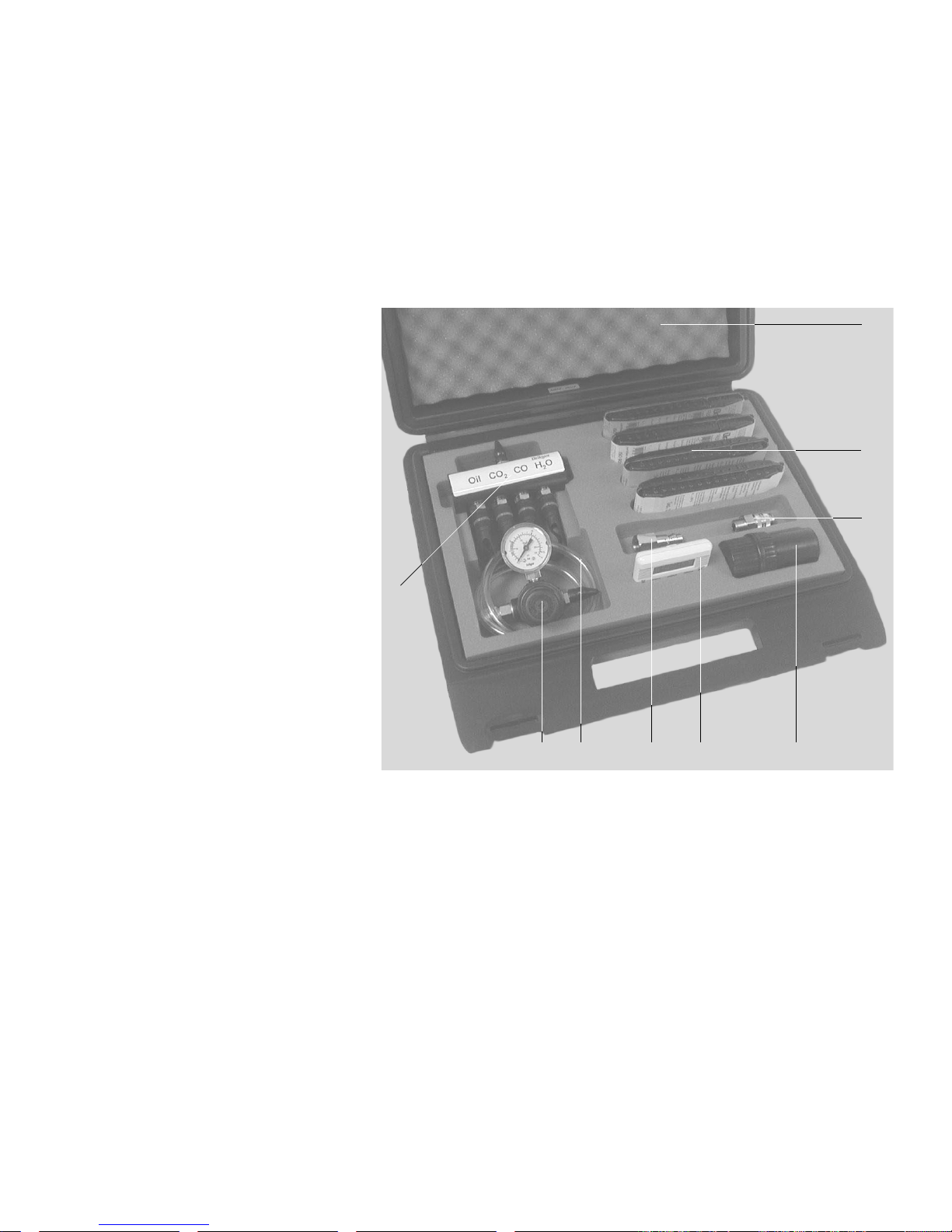
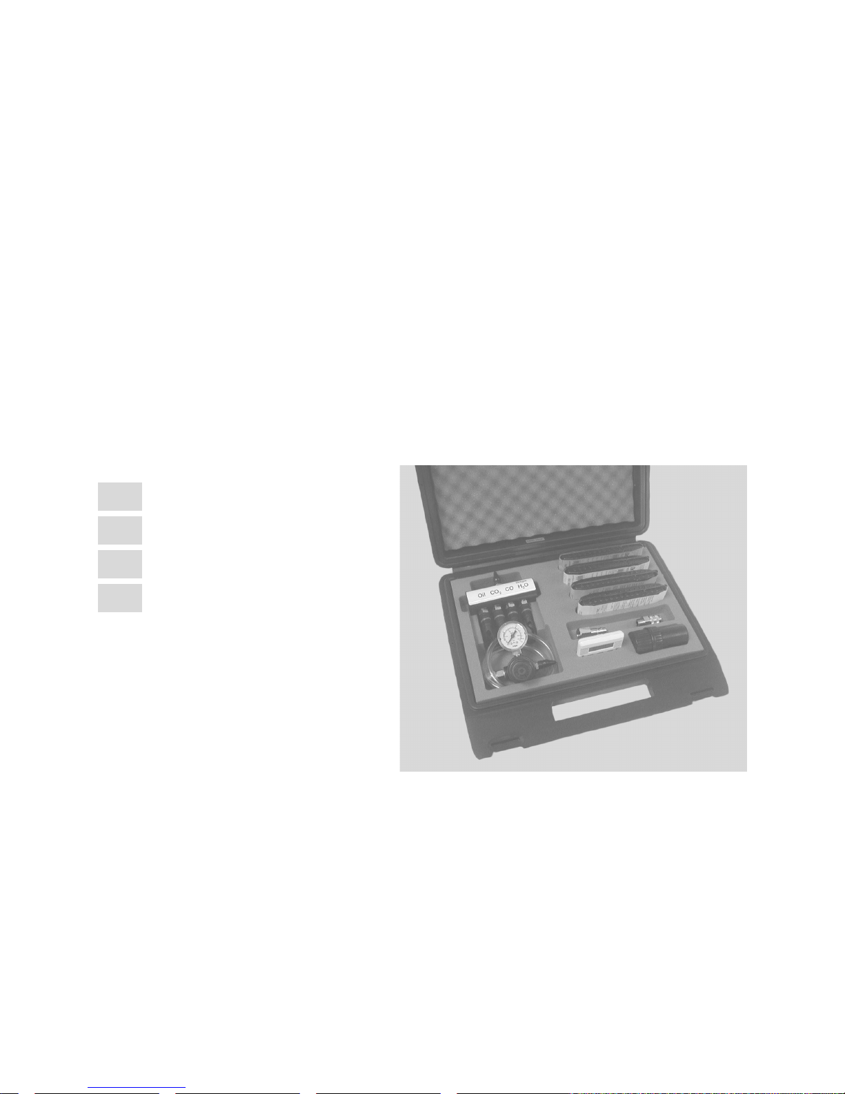
What’s What
1 Carrying case
2 Special Dräger tubes
(4 sets of 10 units)
3 Lock coupling
4 Tube opener for breaking off tube ends
5 Timer
6 Plug fitting
7 Bubble test
pressure regulator with outlet
8 O
2
pressure gauge
9 Measuring unit with four tube holders
®
1
2
3
9
4568 7
00121437.tif
13
Page 4

Description / Intended Use
The Dräger Aerotest Alpha determines the quality of the breathing air
delivered by a low pressure system (compressor, compressed air
cylinder or compressed air network). The maximum supply pressure
at the device inlets is 15 bar. Dräger tubes
measurements.
The levels of the following substances can be measured:
— Oil
— Carbon dioxide (CO
— Carbon monoxide (CO) and
— Water vapour (H
These four values can be defined either simultaneously or individually.
)
2
O).
2
The measurement precision remains constant regardless how many
tube holders are loaded. By contrast, the assigned functions of the
Dräger tubes
®
/ tube holders must be taken into account. In other
words, in order to check e.g. the oil content of the breathing air, the
oil tube must be loaded in the appropriate holder marked “oil“.
The permissible limit values are defined in EN 12 021 (Compressed
air for breathing apparatus).
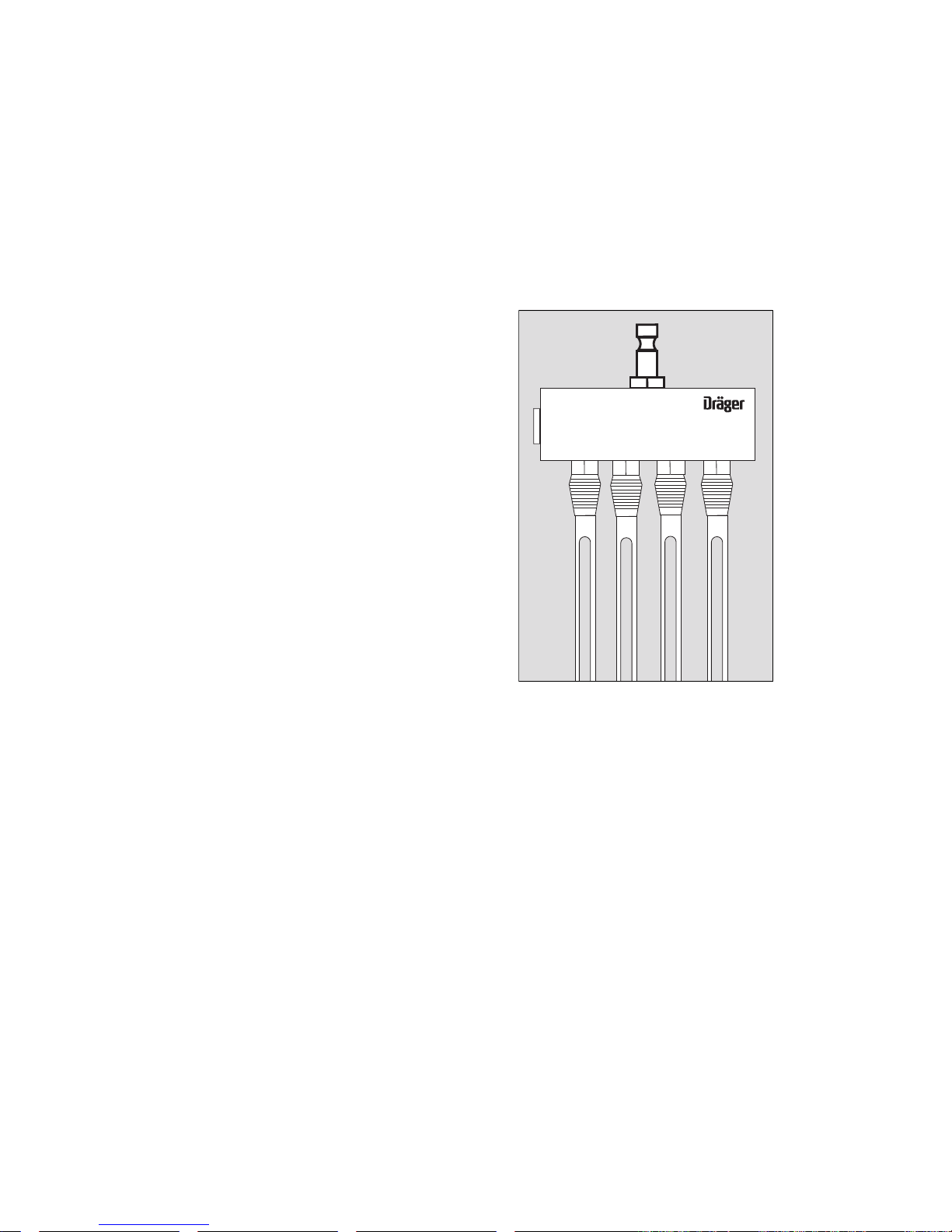
Measuring Unit: Pos. 9
The measuring unit needs a supply pressure of 3 bar.
Pressure Control Valve: Pos. 8
The pressure control valve is preset to 3 bar of relief pressure.
When the supply pressure changes from 3 to 15 bar, the relief pressure (3 bar) at the handwheel of the pressure control valve must be
readjusted. Check via the pressure gauge.
®
are used for the
All the components required for measurement are housed in a handy
carrying case.
14
Page 5
Preparation
p
● Clean the compressed air supply connection by blowing it clear.
● Clean the measuring unit. It must be free of particles and dust.
● Check pass-through of the measuring unit (see page 23).
1 Connect the measuring unit to the compressed air supply
connection. The maximum supply pressure is 15 bar. If necessary,
use the adapter.
Outlet pressure 3 bar adjustable at the pressure-reducing valve
with pressure gauge.
● Slowly open the compressed air supply valve and flush the system
(allow compressed air to be exhausted through the system).
Flushing time for a regularly maintained system:
2 to 3 minutes.
For other systems:
5 to 6 minutes.
● Then close the valve.
● Set the timer: 5 minutes.
Strictly follow the specific Instructions for Use.
1
Oil CO H2OCO
2
s
00321437.e
15
Page 6

Use
p
● Cut off both ends of the “Oil 10/a-P“
tube, using the tube opener. Proceed as follows for both ends:
1 Insert the tube as far as it will go into the middle hole and turn once
or twice. The glass will be scratch-marked.
2 Push the scratched end into the outer hole. The end breaks off and
falls into the container.
Attention!
The broken tube ends have sharp edges.
Risk of injury.
1
2
s
00421437.e
16
Page 7

1 Insert the tube in the “Oil“ tube holder of the measring unit. The
p
arrow on the tube indicates the direction offlow (i.e. arrow must
point away from the measring unit).
Use only Dräger tubes
®
– see “Order List” on page 25.
2 Break off both ends of the “Carbon dioxide 100/a-P“ tube and
insert it in the “CO
3 Break off both ends of the “Carbon monoxide 5/a-P“ tube and
“ tube holder of the measuring unit.
2
insert it in the “CO“ tube holder of the measuring unit.
The “Water vapour 20/a-P“ tube requires special handling:
● Break off the outlet end of the tube.
● Scratch-mark the inlet end of the tube with the tube opener, wit-
hout breaking it off.
● Slowly open the compressed air supply valve.
4 Insert the outlet end of the “Water vapour 20/a-P“ tube in the
O“ tube holder of the measuring unit.
“H
2
● Break off the inlet end in the air stream and simultaneously insert
it in the tube holder.
● Start the timer.
NOTE
Do not inhale the gases released during measurement.
Oil CO H2OCO
2
1 2 3 4
After the test time has elapsed:
● Close the compressed air supply valve. Remove the Dräger tubes
from the tube holder and evaluate the relevant levels with the aid
of the Instructions for Use of the Dräger tubes
®
.
Start by reading off the “Water vapour 20 /a-P“ tube.
s
00521437.e
17
Page 8

After Use
Technical Data
● Dispose of all used tubes and of the broken tube ends in the tube
opener in accordance with the Instructions for Use of the tubes.
● If necessary:
Clean the container of the tube opener and the tube holder with
clean water (only the lower, outlet end) and dry.
Carrying case
Dimensions (length x width x height) 350 x 300 x 85 mm
Colour black
Weight (with full contents) approx. 2 kg
Measuring unit
Dimensions (length x width) 100 x 38 mm
Height including
tube holder 230 mm
Connection for compressed air supply Press-fit nipple, 9 mm
Supply pressure
Minimum 3 bar
Maximum 15 bar
Volumetric flow
Factory-set at 3.0
For CO and CO
For Oil and H
Adapter 1
Inlet Press-fit coupling, 9 mm
Outlet External thread G 1/4
Adapter 2
Inlet Internal thread G 1/4
Outlet Press-fit nipple, 12 mm
tubes 0.2 litres per minute
2
O tubes 4 litres per minute
2
+0.5
bar
18
Environmental conditions 15
1013 mbar
o
C to 25 oC
Page 9

Bubble Test
p
The bubble test is used for the control of the measuring unit, see
“Maintenance Intervals” on page 24. It is tested whether volumetric
flow rate is guaranteed within the measure or a pollution and/or blokkage is available.
1 To this is the delivered bubble test hose plugged into the to be te-
sted connection of the measuring unit.
2 The other end of the bubble test hose is dipped into a water filled
receptacle.
3 With assistance of the timer, the ascending bubbles are counted:
and CO connection, countable blistering
CO
2
(e.g. 40 blow in 15 sec.).
Oil CO H2OCO
2
1
Oil and H
O connection, large blistering (not countable).
2
Storage
Store all parts dry, free of deformation, in a cool and dust-free place.
Protect against direct light and heat sources.
Strictly follow the “Guidelines for the storage, maintenance and
cleaning of rubber products“.
2
3
s
00221437.e
19
Page 10

Troubleshooting
Fault Cause Remendy
Leaky compressed air
connection
Tube not firmly seated
in the tube holder
Tube end not cleanly
scratch market and
broken off
Major measurement
fault
O2 pressure regulator Relief pressure
Defective sealing
ring
Tube holder worn Replace the tube
Tube opener blunt Replace the tube
Tube inserted in
wrong holder
Tube holder dirty or
loose
Wrong volumetric
flow, because the
feed system is
blocked
deviating from 3 bar
Check the sealing
ring and replace if
necessary
holder
opener
Check
Clean or replace the
tube holder
Unscrew the tube
holder from the
measuring unit and
blow the feed insert
clear from both
sides with
compressed air
Readjust on 3 bar
relief pressure
Maintenance Intervals
Device component Maintenance work
Test tube holder Clean X
Test tube Check date of use XX
Measuring device Check volume flow X
*) By Dräger Safety.
required
before each use
after each use
every six months
every year
*)
20
Page 11

Order List
Designation and description Order No.
Dräger Aerotest Alpha
in carrying case, complete with
Dräger tubes
®
(4 sets of 10 units)
Spare parts
Tube opener 64 00 010
Tube holder CH 7000
Plug fitting 65 25 913
Lock coupling 65 25 588
Timer D 40 888
pressure regulator 65 27 151
O
2
Bubble test hose 65 27 686
Consumables
®
1 Set (of 10 units) Dräger tubes
for
Oil 10 /a-P 67 28 371
Carbon dioxide 100/a-P 67 28 521
Carbon monoxide 5/a-P 67 28 511
Water vapour 20/a-P 81 03 061
65 27 150
21
Page 12

42
Page 13

43
Page 14

Dräger Safety AG & Co. KGaA
Revalstrasse 1
D-23560 Luebeck
Germany
Tel. +49 451 8 82 - 0
Fax +49 451 8 82 - 20 80
www.draeger.com
90 21 437 - GA 1651.630 de/en/da/sv
© Dräger Safety AG & Co. KGaA
4th edition - January 2007
Subject to alteration
 Loading...