

Page 1
DR. ZANOLLI s.r.l.
Via Casa Quindici, 22
37066 Caselle di Sommacampagna
(Verona) Italy
Tel +39 045 8581500 (r.a.)
Fax +39 045 8581455
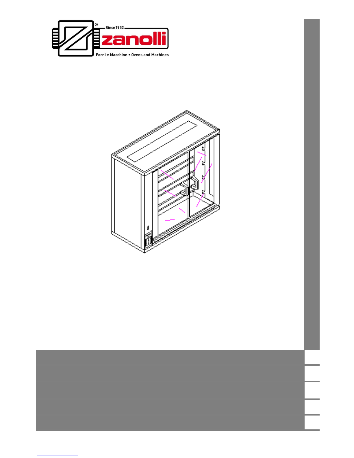
ASADOR G
Manuale di installazione, uso e manutenzione
Manual for installation, use and maintenance
Manual de instalación, uso y manutención
Notice d’installation, d’utilisation et d’entretien
INSTALLATIONS-, BEDIENUNGS- UND INSTANDHALTUNGSHANDBUCH
Page 2

Page 3
Page 4

Dr. Zanolli s.r.l.
Via Casa Quindici, 22
37066 Caselle di Sommacampagna VR
Tel. +39-0458581500 Fax +39-0458581455
VAT N.IT00213620230
Page 5

COD. ASADOR GAS.UK.04 - REV. 0.0 DEL 07/05/2012
ASADOR 5G – 10G – 15G – 20G – 30G – 40G
3
INDEX
1. PRESENTATION ............................................................................. 4
2. HOW TO USE THIS MANUAL ......................................................... 5
3. TECHNICAL SPECIFICATIONS ...................................................... 7
3.1 Identifying the product................................................................... 7
3.2 Conformity to European directives ................................................ 7
3.3 Use intended for the product ......................................................... 7
3.4 Technical specifications ................................................................ 8
4. INSTALLATION ............................................................................... 9
4.1 Checking on delivery ..................................................................... 9
4.1.1 List of disassembled parts supplied ..................................... 10
4.2 Choice of the place of installation the rotisserie .......................... 10
4.2.1 Specifications for areas housing gas ovens ......................... 12
4.3 Moving the unit ........................................................................... 12
4.4 Electrical connection ................................................................... 13
4.5 Connecting the gas ..................................................................... 15
4.6 Emissions from Cooking Appliances ........................................... 15
4.7 Checking before starting work .................................................... 16
5. FUNCTIONING AND USE .............................................................. 17
5.1 Preparing the rotisserie for use ................................................... 17
5.2 Turning on the spits and rotisserie .............................................. 17
5.3 Opening and closing the glass doors ................................ .......... 17
5.4 Loading and inserting the spits ................................................... 18
5.5 Removing the spits ..................................................................... 18
6. SAFETY WARNINGS ..................................................................... 19
6.1 Avoiding danger and taking responsibility for safety ................... 19
7. CLEANING ..................................................................................... 20
5.2 Cleaning the protection between the burners .............................. 21
8. MAINTENANCE ............................................................................. 22
8.1 Removing the fixed side protection ............................................. 22
8.2 Adjusting the chain ..................................................................... 22
8.3 Changing the type of gas supply ................................................. 23
8.3.1 Regulating the...................................................................... 24
8.4 Exploded Diagrams ..................................................................... 26
8.5 Wiring diagram ............................................................................ 29
9. DECOMISSIONING AND DEMOLITION ........................................ 30
Page 6

1. PRESENTATION
ASADOR 5G – 10G – 15G – 20G – 30G – 40G
4
1. PRESENTATION
Of the Rotisseries in the ASADOR range, the 5G, 10G, 15G, 20G, 30G
and 40G have overlapping spits.
ASADOR rotisseries have been designed and constructed to a high
standard of quality and ease of maintenance so they last longer. We can
boast of rotisseries that are still giving good service after 20 years.
The construction of the oven has been undertaken with care: the use of
stainless steel both in the casing and in the cooking chamber ensures
extremely easy cleaning and a long working life to the product even with its
repeated use for cooking foods with a high level of salt and humidity, etc.
Manufacturer thanks you for the preference expressed in purchasing this
product. We can confidently assure you that it is a good choice. Our
company has been committed to the manufacture of quality products for
many years. We do not believe in making compromises and use the best
possible materials.
To get the best use out of your new Rotisserie oven please read the
information contained in this manual carefully.
Page 7

2. HOW TO USE THIS MANUAL
ASADOR 5G – 10G – 15G – 20G – 30G – 40G
5
2. HOW TO USE THIS MANUAL
The paragraphs marked with this symbol contain indications
essential to safety. They must all be read by installers, the end user
and any employees that use the machine. The manufacturer does not
assume any responsibility for damage or injury incurring as a result
of ignoring the safety criteria outlined in these paragraphs.
This symbol, applied to various points on the machine, serves
to warn the user of the presence of a non-insulated “high voltage
hazard” inside the machine’s casing there being enough power to
constitute a fire risk or to electrocute a person.
The paragraphs marked with this symbol contain important
information to avoid causing damage to the oven. It is in the users
own interests to read these paragraphs carefully.
It is recommended that this installation, instruction and service
manual be kept in close proximity to the equipment so that it can be easily
and quickly consulted. The manual must accompany the equipment if it is
resold as it cannot be considered complete and safe without it.
Take note of the code shown on the back cover. In the event that this
copy is lost or destroyed, you can order another copy using the details
mentioned later in the manual. It would be a good idea to write this code
down on a separate piece of paper.
This manual is made up of a number of chapters. They should be
read in their entirety by both installers and service personnel as well as by
the end user to ensure getting the best results from this product.
Nevertheless, a rapid consultation of the various chapters may
sometimes be necessary and to facilitate this, a brief summary of their
contents is given below.
Chapter 3 contains the specifications of the oven and all the values that
are necessary for choosing the right environment for its installation and
use. This chapter should be used as a point of reference to check that the
equipment is being used in the way intended and ensure that information
concerning the precise value of a given measurement or tolerance of the
equipment is available whenever necessary.
Page 8

2. HOW TO USE THIS MANUAL
ASADOR 5G – 10G – 15G – 20G – 30G – 40G
6
Chapter 4 contains all the information needed to install the oven. These
are mainly aimed at specialized personnel but should be read by the end
user beforehand so as to predispose the environment where the machine
will be operated for the installation.
Chapters 5 and 6 serve as a guide to the user in the essential
operations of turning on, using and turning off the machine under safe
conditions.
Chapter 7 supplies all the information necessary for the cleaning of the
equipment: all those operations that must be carried out by the user to
guarantee that it continues to function under safe conditions (above all
those concerning hygiene) and continues to give the best results.
These maintenance operations must be carried out by
specialized personnel.
Chapter 8 This chapter completes the part of the manual concerning
maintenance with a series of exploded diagrams of the appliance to help in
ordering and substituting its various parts if damaged. It gives a list of the
electrical equipment supplied with the appliance.
Chapter 9 offers information in the event that the machine is no longer
used for a prolonged period.
Page 9

3. TECHNICAL SPECIFICATION
ASADOR 5G – 10G – 15G – 20G – 30G – 40G
7
3.TECHNICAL SPECIFICATIONS
3.1 Identifying the product
This manual refers to ASADOR rotisseries 5/G, 10/G, 15/G, 20/G, 30/G
and 40/G
3.2 Conformity to European directives
ASADOR 5/G, 10/G, 15/G, 20/G, 30/G e 40/G cooking units carry the
following obligatory mark, guaranteeing their conforming to the
following European directives:
2014/35/CE Low Tension Directive
2014/30/CE Electromagnetic Compatibility Directive
2006/42/CE Machines Directive
2009/142/CE Gas Directive
1935/2004/CE Regulation for Equipment intended to come into Contact
with Foodstuffs
3.3 Use intended for the product
ASADOR rotisserie are designed for cooking various types of meat and
fish of small to medium size such as chicken, guinea fowl, quails and
wildfowl, cuts of beef and pork up to 2kg in weight, etc. ASADOR
rotisseries are conceived for professional use in the foodservice
industry by trained personnel.
The rotisserie has been designed for performing the following operations
during normal use: the opening and closing of the protective glass, the
loading and unloading of the meat from the spits or any other accessories,
the turning on, regulation and turning off of the equipment and cleaning it
completely.
Page 10
3. TECHNICAL SPECIFICATION
ASADOR 5G – 10G – 15G – 20G – 30G – 40G
8
3.4 Technical specifications
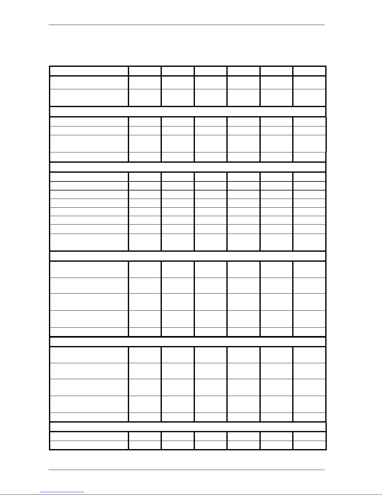
The following table shows the technical specifications for this cooking unit
5/G
10/G
15/G
20/G
30/G
40/G
Weight
50 kg
63 kg
80 kg
95 kg
160 kg
183 kg
External dimentions
(lxdxh)
116x48x
46 cm
116x48x
64 cm
116x48x
82 cm
116x48x
100 cm
116x48x
186 cm
116x48x
192 cm
ELECTRICAL POWER SUPPLY
Electrical power
0.02 kW
0.02 kW
0.02 kW
0.02 kW
0.02 kW
0.02 kW
Num. Motors
1 1 1 1 1
1
Motor Voltage – Num.
Phases-Frequency
230V 1N
50 Hz
230V 1N
50 Hz
230V 1N
50 Hz
230V 1N
50 Hz
230V 1N
50 Hz
230V 1N
50 Hz
Current
0.1 A
0.1 A
0.1 A
0.1 A
0.1 A
0.1 A
GAS SUPPLY
Exhaust type
A A A A A
A
Renewal rate
12 m3/h
24 m3/h
36 m3/h
48 m3/h
71 m3/h
95 m3/h
Flame ingnition
Manuale
Manuale
Manuale
Manuale
Manuale
Manuale
Flame control
Sonda
Sonda
Sonda
Sonda
Sonda
Sonda
Security time
- sec
- sec
- sec
- sec
- sec
- sec
Maximum Power
5.9 kW
11.8 kW
17.7 kW
23.6 kW
35.4 kW
47.2 kW
Reduced Power
3 kW
5.9 kW
8.9 kW
11.8 kW
17.7 kW
23.6 kW
Number of burners
and jets
1 2 3 4 6
8
PREPARATION G20
Maximum capacity
0.624
m3/h
1.249
m3/h
1.873
m3/h
2.497
m3/h
3.746
m3/h
4.995
m3/h
Reduced capacity
0.317
m3/h
0.624
m3/h
0.942
m3/h
1.249
m3/h
1.873
m3/h
2.497
m3/h
Pressure at jet at
maximum capacity
20 mbar
20 mbar
20 mbar
20 mbar
20 mbar
20 mbar
Pressure at jet at
reduced capacity
5mbar
5mbar
5mbar
5mbar
5mbar
5mbar
Ø main jet
1.90
1.90
1.90
1.90
1.90
1.90
PREPARATION G30-G31
Maximum capacity
0.462
kg/h
0.923
kg/h
1.385
kg/h
1.847
kg/h
2.770
kg/h
3.693
kg/h
Reduced capacity
0.235
kg/h
0.462
kg/h
0.696
kg/h
0.923
kg/h
1.385
kg/h
1.847
kg/h
Pressure at jet at
maximum capacity
30 mbar
30 mbar
30 mbar
30 mbar
30 mbar
30 mbar
Pressure at jet at
reduced capacity
7.5 mbar
7.5 mbar
7.5 mbar
7.5 mbar
7.5 mbar
7.5 mbar
Ø main jet
1.20
1.20
1.20
1.20
1.20
1.20
ENVIRONMENTAL CONDITIONS
Temperature
0°/40° C
0°/40° C
0°/40° C
0°/40° C
0°/40° C
0°/40° C
Maximum humidity
98%
98%
98%
98%
98%
98%
Table 3.1 Technical specification
Page 11

4. INSTALLATION
ASADOR 5G – 10G – 15G – 20G – 30G – 40G
9
4. INSTALLATION
ATTENTION! These installation instructions are for the
exclusive use of personnel qualified for the installation and
maintenance of electrical and gas equipment conceived for
professional use in the foodservice industry and community catering
operations.
An installation carried out by unqualified persons could cause damage to
the oven, to people, animals or property
ATTENTION! Proceed with the installation according to those
norms in force in the country where it is being carried out.
In addition, where it is necessary to carry out modifications or
adaptations to the electrical or gas systems of the building in which the
oven will be installed, whoever carries out such modifications must certify
that the work has been undertaken according to current “best practices”.
4.1 Checking on delivery
Unless otherwise agreed, the products are carefully packaged in a
robust structure in wood and with a sheet of nylon bubble wrap giving
protection against knocks and humidity during transport. These are
consigned to the freight operator in the best of condition.
We recommend, however, that you to check the packaging on arrival for
any signs of damage. If damage has occurred, have it noted on the receipt
which must be signed by the driver.
Once the equipment has been unpacked, check that it has not suffered
damage. Also check that all the dissembled parts are present.
In the event of damage to the equipment and/or missing parts, bear in
mind that the freight operator can only accept claims within 15 days of
delivery and that the manufacturer cannot be held responsible for damage
incurred to its products during their delivery. We are however, available to
assist you in presenting your claim.
In the event of damage do not try to use the equipment and
consult with professionally qualified personnel.
Page 12
4. INSTALLATION
ASADOR 5G – 10G – 15G – 20G – 30G – 40G
10
4.1.1 List of disassembled parts supplied
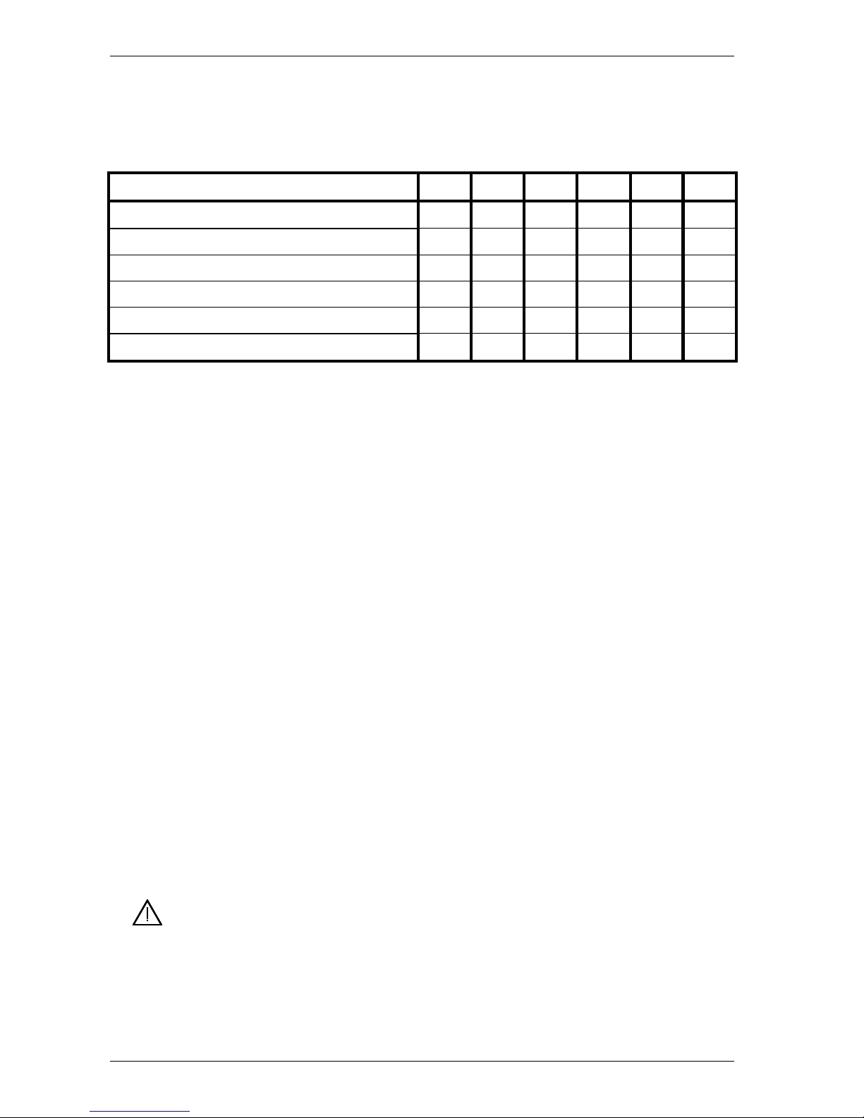
Check that all the disassembled parts are included. To help with this,
refer to the following checklist for the parts supplied (Tab. 4.1).
DESCRIPTION
5E
10E
15E
20E
30E
40E
Tray
1 1 1 1 1
1
Spits
1 2 3 4 6
8
Central forks
4 8 12
16
24
32
Side forks
2 4 6 8 12
16
Hook to remove the spits
1 1 1 1 1
1
Users manual
1 1 1 1 1
1
Table 4.1 List of the parts supplied together with the rotisserie
The dripping pan is usually positioned at the bottom of the rotisserie in
the working position whilst the other parts are wrapped and placed inside.
Depending on the order and the arrangements that have been made, the
rotisserie can be consigned and packaged in the following three
configurations:
- with feet for placing on table or worktop;
- with trestle in stainless steel complete with wheels;
- with warming cabinet.
A plug for the power cable is not supplied together with the other
components.
4.2 Choice of the place of installation the rotisserie
An effective, safe and long lasting functioning of the appliance also
depends on the position in which it is installed. For this reason, it is
advisable to carefully consider where to install the equipment before it is
delivered.
Install the appliance in a dry and easily accessible place both to facilitate
its use and to carry out cleaning and maintenance. The area around the
equipment must be kept clear. It is particularly important to avoid
obstructing the cooling outlets located on the sides of the rotisserie oven.
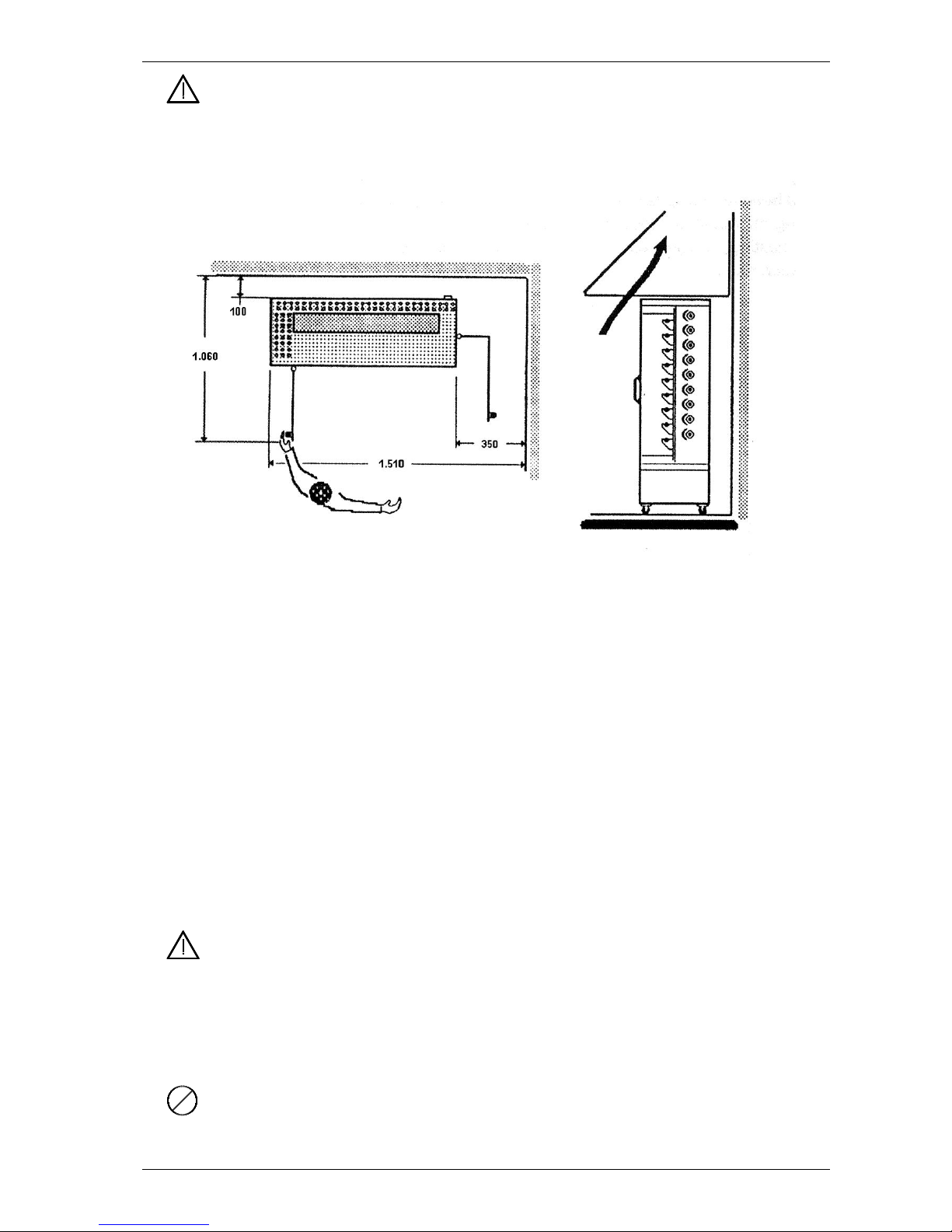
The appliance must be installed at least 10cm from the walls of the
room or from other equipment so that the ventilation outlets located on the
sides of the rotisserie are not obstructed.
Page 13
4. INSTALLATION
ASADOR 5G – 10G – 15G – 20G – 30G – 40G
11
When installing the unit give enough clearance for the right door,
this swings open from the side of the unit and protrudes beyond the
external dimensions of the unit when open (see Fig. 4.1).
Fig. 4.1
Whilst in operation, cooking equipment produces vapour and cooking
smells that compromise the integrity of a healthy working environment.
In the case of electric ovens, even if it is not obligatory, the installation of
an extraction fan and hood is recommended to improve conditions in the
working environment and to avoid damage to the ceiling of the area where
it is housed caused by hot, oily fumes.
If the rotisserie is supplied with feet, it should be placed on a work
surface being of a suitable height and strong enough to sustain the weight
of the equipment.
If the rotisserie is supplied with a warming cabinet, see the separate
instructions for this equipment.
The moving doors of the cooking area are made out of tempered
glass and are therefore particularly susceptible to sudden variations in
temperature that could cause their breaking into small fragments.
For safety reasons the rotisserie cannot be installed in areas accessible
to the public.
To avoid the glass breaking, do not install the rotisserie in places
where there are drafts or near to doors or windows. Take care when
Page 14
4. INSTALLATION
ASADOR 5G – 10G – 15G – 20G – 30G – 40G
12
moving the rotisserie from cold to warm areas and vice versa. Make sure
that the equipment has come up to room temperature before putting it to
use.
A check must be made to ensure that the temperature and relative
humidity never exceed the maximum and minimum values indicted in the
specifications (see Tab. 3.1) even when the rotisserie or other ovens in the
room are functioning.
Exceeding these values especially the temperature or the maximum
relative humidity can easily and unexpectedly damage electrical equipment
creating hazardous situations.
4.2.1 Specifications for areas housing gas ovens
It is the installer’s responsibility to check that the gas system
of the room in which the oven will be installed is working properly
and that the ventilation and aeration conduits of this room function as
required for the nominal heat input.
The Manufacturer cannot answer for damage caused by
failure to observe the norms in force for the installation of gas
equipment.
During the installation, care must be taken to avoid obstructing the
cooling vents and the air intakes for combustion air built into the oven.
When dealing with gas equipment, the room in which it will be installed
must be sufficiently ventilated and aerated. To ensure this, the enclosed
area in which it will be housed must have at least two permanent apertures
leading directly through its walls leading to the open air.
As an indication, for every kW of power installed, an air renewal rate of
36 m3/h is recommended.
To get a clear idea of the specifications required for the housing location,
refer to the norms in force in the country where the installation is being
carried out, in particular those prescribed for
4.3 Moving the unit
To move the rotisserie together with the warming cabinet, refer to
the instructions for the cabinet.
To offload and transport the unit while it is packed, a pallet truck or a
transpallet lifter with a load capacity at least equal to that of the unit should
be used. Insert the forks in the spaces provided at the base of the packing.
Page 15

4. INSTALLATION
ASADOR 5G – 10G – 15G – 20G – 30G – 40G
13
To offload and transport the unit without packaging, use a forklift truck or
transpallet having a load bearing capacity at least equal to that of the unit.
Introduce the forks from the back or from the front of the space that
remains between the surface on which the rotisseries feet rest and the
bottom of the rotisserie.
To avoid damage, place protective material between the forks and
the unit.
In all situations, to avoid unpredictable movement, be aware of the
equipment’s centre of mass.
Take care that children do not play with the packaging materials
(e.g., plastic sheeting and Styrofoam): suffocation danger!
4.4 Electrical connection
Before making any connection, check that the specifications of the
electrical supply to which the equipment must be connected, correspond to
the specifications of the power supply required by the apparatus itself (see
Tab. 3-1).
The appliances are supplied with an electric connection with
ground/earth cable for connecting the appliance to the power grid
according to the supply required (see Tab. 3.1).
In compliance with the norms in force. It is obligatory to connect the
ground/earth cable (yellow-green) to an earthing system with the
same dispersion capacity as the appliance itself. The efficiency of this
system must be correctly verified according to the norms in force.
The power cable must terminate with a plug to connect to the electrical
switchgear having a corresponding differential magneto thermal switch.
The equipment is not supplied with a power plug.
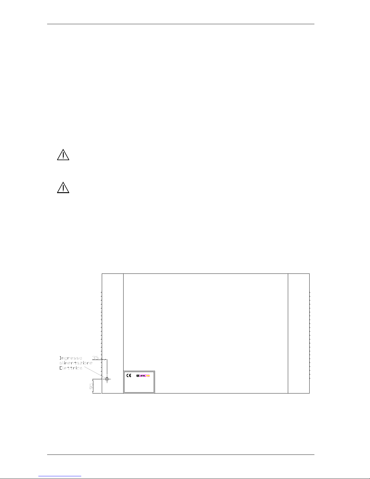
Data regarding the power supply is given on a plate positioned on the
back of the oven, near the power connection entry point (see Fig. 4.2).
The coupling between plug and socket must be such that the earth
conductor is connected first and disconnected last and must have the right
dimensions for the rated current (see Table 3.1). Plugs and sockets for
Page 16
4. INSTALLATION
ASADOR 5G – 10G – 15G – 20G – 30G – 40G
14
industrial use of the type CEE17 are suitable or those which satisfy
European norm EN 60309.
The thermal circuit breaker must be calibrated to the total rated current
and the magnetic circuit breaker calibrated to the rated current (In the case
of ovens this is only slightly higher than rated current), while the differential
mechanism must be calibrated to the 30 mA current (see Table 3.1).
The electrical socket must be easily accessible and must not require
further location after the installation of the equipment. The distance
between the equipment and the socket must be sufficient to avoid
stretching the power cable.
The power cable must never be trapped under the feet or wheels of
the equipment.
If the Power cable is damaged it must be substituted by
customer support or by a qualified service engineer so as to avoid
any risk.
The Manufacturer does not accept responsibility for damage caused by
failure to observe the abovementioned norms.
For the position of the electrical power connections, see Fig. 4.2.
Fig. 4.2 Positioning of electrical connection and plate
Page 17

4. INSTALLATION
ASADOR 5G – 10G – 15G – 20G – 30G – 40G
15
4.5 Connecting the gas
Before making any type of connection, ensure that the type of gas
and pressure of the supply for which the equipment has been calibrated
corresponds to the type and the pressure of the gas that is available. This
is indicated on the initial regulation label applied to the identification plate.
Should these not correspond, refer to paragraph 8.4 to change the
regulation.
Gas appliances have a gas input with a G1/2” conic thread as
indicated in the specifications. The connection to the building’s gas supply
must be made by means of metallic tubing in zinc plated steel or in copper,
exposed to view.
The equipment must be connected to the gas mains supply with an
easily operated mains tap.
The connection of the tubing to the equipment must be made with a
three piece metal joint to facilitate disassembly.
The strength of the gas tightness on the threaded joint must be ensured
with materials specifically declared to be suitable by their manufacturer
also for methane and GPL gasses.
4.6 Emissions from Cooking Appliances
This oven produces waste gasses classified as type “A” (see
Tab. 3.1): equipment not intended for connection to a chimney or flue
or a device for the evacuation of the combustion residue into the
open air from the room in which the equipment is installed. The
drawing in of combustion air and the expelling of combustion
exhaust takes place in the room where the oven is installed.
To install type “A” equipment, rooms in which it is housed must
be aerated and ventilated. They must specifically respect the
conditions concerning the flow of air necessary for combustion and
aeration of these spaces and for the disposal of combustion residue.
ATTENTION! Proceed with the installation according to those
norms in force for this type of oven in the country where it is being
carried out. For further information consult these norms.
To find out the nominal heat input of your oven, see Tab 3.1.
Page 18

4. INSTALLATION
ASADOR 5G – 10G – 15G – 20G – 30G – 40G
16
When more than one or more cooking units are stacked one on top
of another, to calculate the nominal heat input simply sum the power
of each single unit.
The area in which the units will be housed must have at least two
permanent apertures leading directly through its walls into the open air:
- one for the intake of combustion air, ventilating the room;
- the other for disposing of combustion gasses, aerating the room.
The two apertures must be in such a position so as not to create a shortcircuit in the flow of air: preferably they should be at opposite ends of the
room, they must not be obstructed and must be protected with grilles.
The necessary aeration can be achieved naturally or by way of the
installation of a forced aeration system depending on the norms in force in
the country where the installation is being made for ovens with a type “A”
exhaust.
Be aware of the total thermal input of the ovens housed in
each room in a situation in which more than one unit is being
installed.
The manufacturer cannot answer for damage caused by
ignoring these abovementioned norms as well as the information in
this manual.
4.7 Checking before starting work
After completing installation of the unit a series of checks must be
carried out, listed as follows:
- check that the various disassembled parts have been assembled
- check the power cable
- check that the control panel is working
- check the integrity of the jointing for gas supply and exhaust tubes
- check that the apertures for ventilating the room are adequate
- check the rated flow capacity of the oven while it is functioning at the
exit point of the solenoid valve
- if fitted, check that the ventilation hood is working
Page 19

5. FUNCTIONING AND USE
ASADOR 5G – 10G – 15G – 20G – 30G – 40G
17
5. FUNCTIONING AND USE
5.1 Preparing the rotisserie for use
If the rotisserie has just been installed or if it has lain idle for a
number of days, it needs to be completely cleaned as indicated in chapter
7 before using it for cooking. This is to eliminate residues left over from the
manufacturing process and the accumulation of dust or other substances
that could contaminate food products.
Before turning the oven on, ensure that glass surfaces are clean and
dry.
5.2 Turning on the spits and rotisserie
The switch activating the motor is located on the left side of the unit.
Apart from setting the spits in motion, this switch illuminates to show that
power is being supplied to the oven and that it is effectively turned on.
The knobs for opening the valves that control each burner are on the
right side of the rotisserie, corresponding to the position of each spit. To
light the gas, position a naked flame near to the burner and rotate the
knob in an anticlockwise direction by a ¼ of a turn (Max). To turn off put
the knob back to the zero position by turning it in a clockwise direction. To
reduce the temperature of the burner to a minimum turn the knob to the
minimum position.
5.3 Opening and closing the glass doors
The rotisseries ASADOR 5G,10G, 15G, 20G, 30G e 40G have two
vertically hinged doors made out of tempered glass which open on each
side. These doors are designed to protect the operator from the heat
released whilst the equipment is in use and to protect the food products
from being contaminated by external pollutants.
The glass door on the right side protrudes beyond the external
dimensions of the rotisserie(Fig. 4.1).
Avoid banging against the glass, this could cause it to immediately
fracture or it could break later without there being any apparent cause.
Page 20

5. FUNCTIONING AND USE
ASADOR 5G – 10G – 15G – 20G – 30G – 40G
18
5.4 Loading and inserting the spits
The spits are provided with forks for keeping chickens in place.
Insert a fork from the free end and slide it down to the opposite end so
that the prongs are pointing inwards. Lock it into position using its wing nut.
Insert a chicken, a double fork, another chicken and so on. When a good
number of chickens have been arranged insert a fork and fix it using its
wing nut.
Once the spit has been prepared, grasp it by the right end handle,
supporting the left side with the hook, introduce the left end into the square
seat of the turning mechanism and rest it on the supporting bush.
Ensure that the dripping tray is positioned at the bottom of the cooking
bay.
5.5 Removing the spits
Attention! When the meat is done, the spits and their handles are at
a dangerously high temperature. To avoid burning, protective gloves
must be used apart from using the hook provided.
Attention! To avoid burning, this operation must be carried out with
the elements turned off.
To take out a spit, open the doors completely, insert the hook under the
left end of the spit, lift the right end and bring it slowly toward the front of
the bay with a gradual movement towards the right so as to slip the left end
out of the motor axle. Having done this, extract the spit completely from the
cooking bay.
Page 21

6. SAFETY WARNINGS
ASADOR 5G – 10G – 15G – 20G – 30G – 40G
19
6. SAFETY WARNINGS
6.1 Avoiding danger and taking responsibility for safety
Read the warnings listed in this chapter carefully. They give
important indications concerning safety.
Never turn the equipment on with the cooking chamber empty and the
glass doors closed.
Check the efficiency of the earthing.
Use protective gloves for handling spits and the dripping tray.
Do not modify or handle the security systems or the electric circuits.
Maintain the security systems of the rotisserie in a good state.
The use of the upper part of the rotisserie as a shelf or storage surface
is prohibited.
Do not introduce inflammable materials into the rotisserie or use it to dry
varnishes and solvents.
Do not introduce compounds into the rotisserie that could leave
explosive and/or inflammable mixtures.
It is prohibited to install accessories that do not conform to safety
standards.
Do not use the equipment in an inappropriate way but stick scrupulously
to using it in the way it was intended.
In case off fire do not use liquid but exclusively powdered extinguishing
agents.
Have your equipment regularly inspected by a qualified technician to
guarantee your safety.
Page 22

7. CLEANING
ASADOR 5G – 10G – 15G – 20G – 30G – 40G
20
7. CLEANING
Cleaning should be carried out with the equipment turned off
and at room temperature having taken the precaution of
disconnecting the electricity supply.
Weekly maintenance can be carried out by the equipment’s operator
given that they observe the safety procedures set out in this manual.
Do not direct jets of water onto the equipment for clearing as these
can penetrate through to and damage the electrical system with the
consequent risk of electrocution and the equipment starting up
unexpectedly.
Use a vacuum cleaner to generally clean the rotisserie. This should be
carried out especially in the cooking bay, with the motors and on the
control panel.
To clean the stainless steel or aluminum coated sheet steel cooking
chamber and the coated or chromed parts use a soft moistened sponge
and if needs be a weak non abrasive detergent. Rinse and dry with a soft
clean cloth.
If there is a consistent amount of fat deposited on the surfaces remove it
first using a plastic spatula.
It is a good idea to first wash the various removable parts before food
residues on them dry and go hard (see Ch. 7.1).
Do not use abrasive tools (abrasive sponges, etc.) because these
will cause the stainless steel and glass parts to become opaque and will,
quite quickly, remove the protective layer of aluminum coated sheet steel,
at which point it will start to rust.
The tempered glass parts are particularly sensitive to sudden
variations in temperature that can cause them to crack into tiny fragments.
Do not handle glass parts and do not bring them into contact with
water until they have cooled down to room temperature.
Do not use detergents containing chlorine.
Page 23
7. CLEANING
ASADOR 5G – 10G – 15G – 20G – 30G – 40G
21
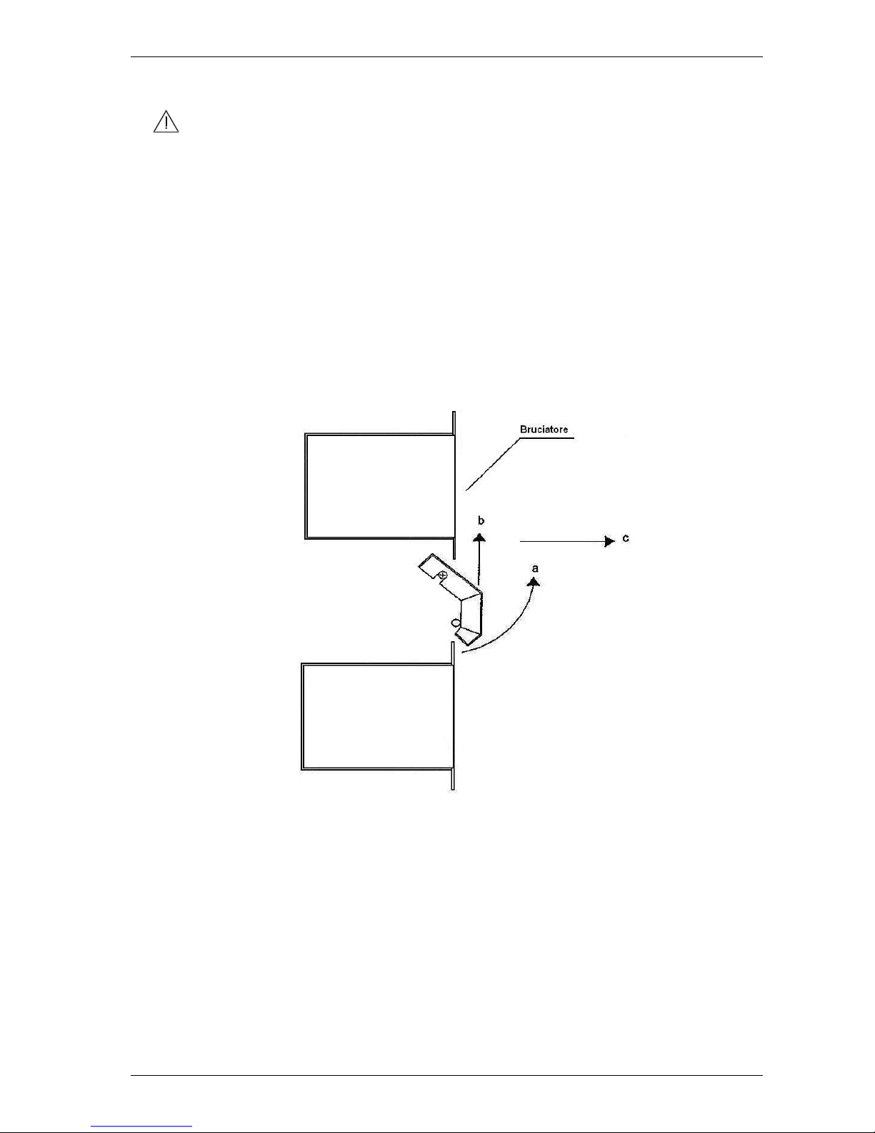
5.2 Cleaning the protection between the burners
Before removing any fixed protection make sure that the equipment
has been unplugged from the supply socket.
This protection can be found between the various burners-element
groups and is extractable to facilitate easy cleaning to be carried out
according to the instructions below:
- Lift the lower part of the burner protection and bring it into a horizontal
position (a, Fig. 7.1);
- Lift the protection from the horizontal position (c, Fig. 7.1); proceed to
extracting it smoothly;
- Carry out these actions in reverse order to reinsert the protection.
Fig. 7.1
Page 24

8. MAINTENANCE
ASADOR 5G – 10G – 15G – 20G – 30G – 40G
22
8. MAINTENANCE
WARNING! These use and maintenance instructions are
intended only for a staff qualified for the installation and
maintenance of electrical and gas equipment. Maintenance by other
persons may cause damage to the equipment, persons, animals or
property.
In the majority of cases it is necessary to remove the fixed guards in
order to carry out repairs and checks. This also renders the voltage cables
accessible. Before carrying out any fixed protection, check that the
rotisserie’s feed cable plug is disconnected from the switchboard.
Put the plug in a place where the maintenance operator can easily
ascertain that it has been disconnected during all of the work done
with the guards removed.
8.1 Removing the fixed side protection
Before removing any fixed protection check that the equipment’s
feed cable plug is disconnected from the switchgear.
To remove each of the fixed side protectors, unscrew the screws that fix
them to the rotisserie.
Reconnect the plug to the power supply socket only after having put
back all fixed protection.
8.2 Adjusting the chain
Before removing any fixed protection make sure that the equipment
has been unplugged from the supply socket.
To remove the fixed side protectors, unscrew the four screws that fix
them to the rotisserie.
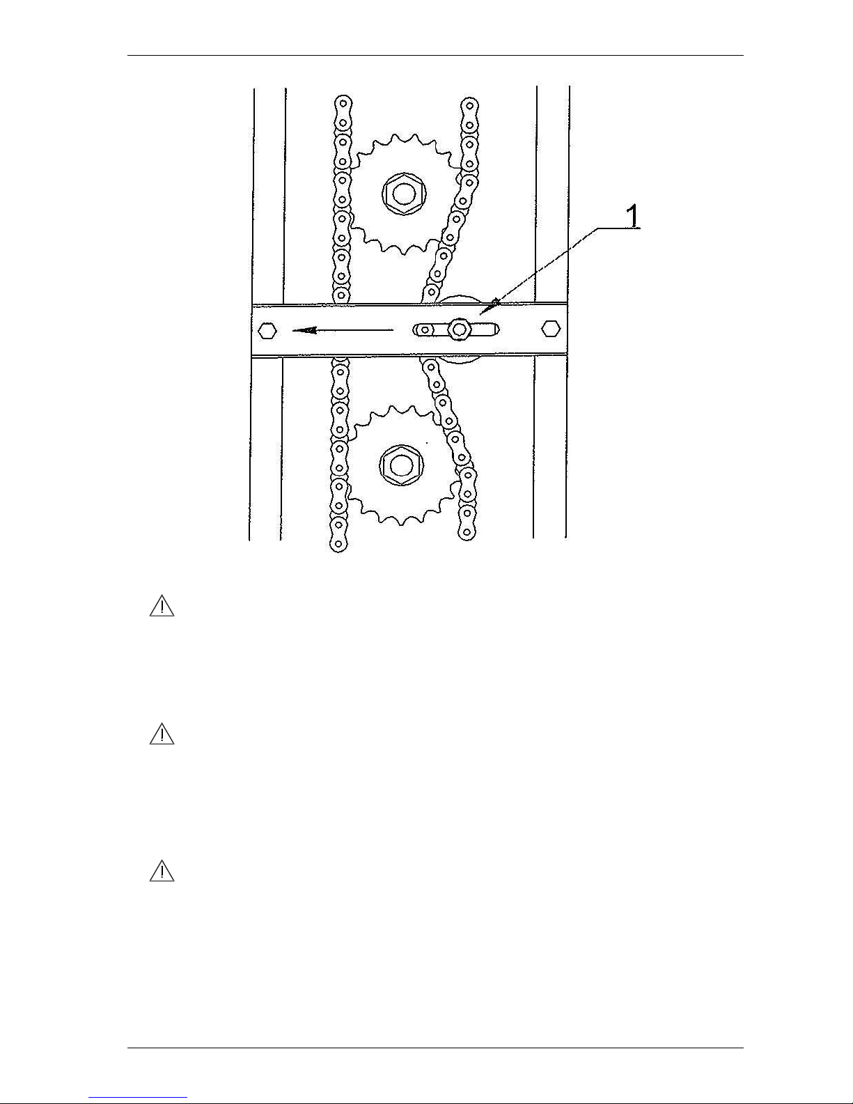
To regulate the chain, slightly loosen the bolt 1 (Fig. 8.1) and move the
tensor towards the left, (see arrow) fixing it in the appropriate position.
Then go on to tighten the bolt.
Page 25
8. MAINTENANCE
ASADOR 5G – 10G – 15G – 20G – 30G – 40G
23
Fig. 8.1
For optimum performance, the chain must have about 1cm of
elasticity. An excessively tight chain will put unnecessarily load on the
motor.
8.3 Changing the type of gas supply
WARNING! The instructions for the procedure that follows are
intended for use by maintenance instructions are intended only for a
staff qualified for the installation and maintenance of electrical and
gas equipment. Maintenance by other persons may cause damage to
the equipment, persons, animals or property.
Ensure that the main gas tap is closed.
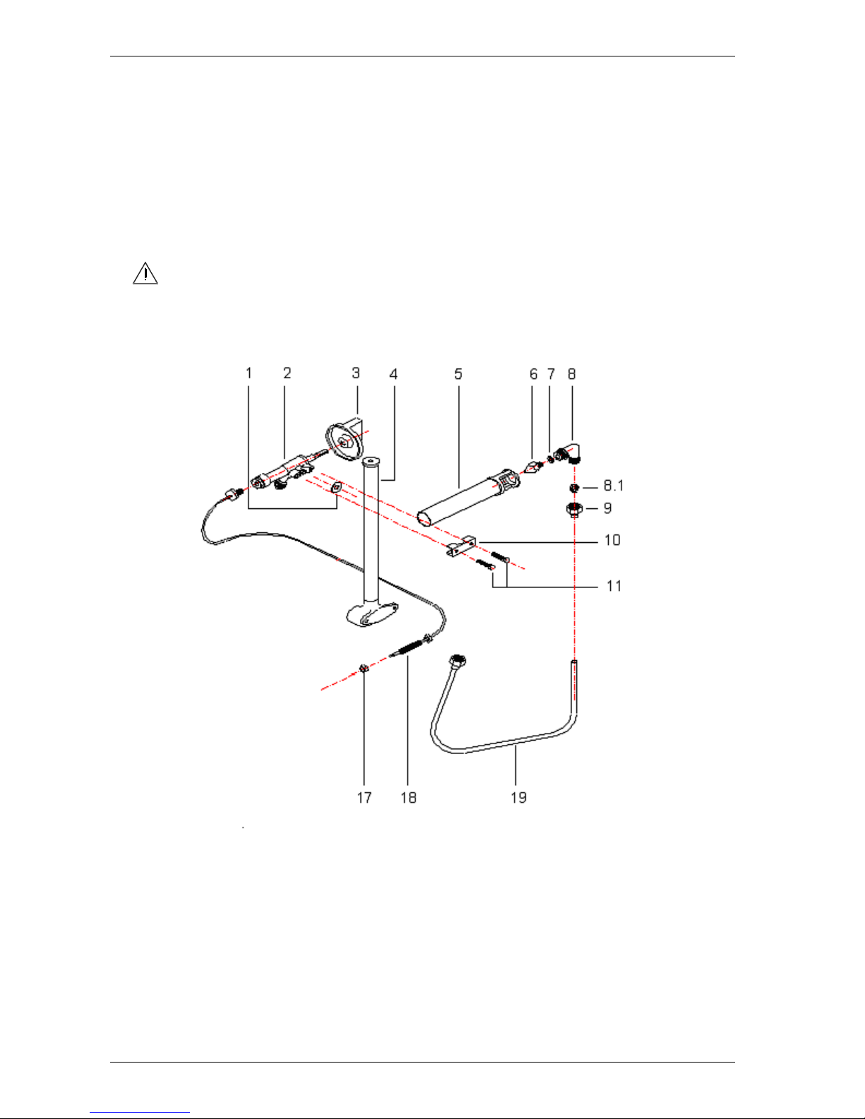
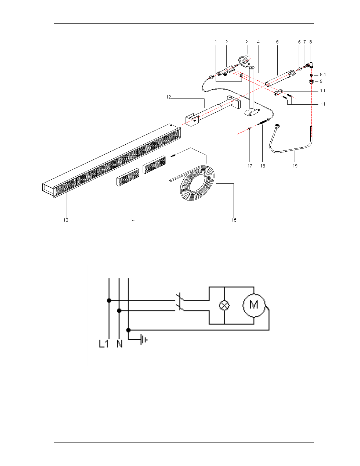
1. Extract the security valve knob (3) (Fig. 8.2).
2. Unscrew the screws that fix the cover to the command panel.
3. Completely unscrew the screws (9) and extract the tube (19).
4. Extract part (8). Take out parts (5); (6) and (7).
Page 26
8. MAINTENANCE
ASADOR 5G – 10G – 15G – 20G – 30G – 40G
24
5. Unscrew (8) and change the jet (6) with one appropriate for the
dimentions for the type of gas (Tab. 3.1). The diameter of the jet is
shown on the its side. Do not forger to substitute the gasket with a new
one.
6. Follow these instructions in reverse order for reassembly.
7. Repeat the procedure for each burner.
8. Once this operation is finished, check that there are no leaks and close
the panel with its screws.
ATTENTION! After changing the gas supply it is necessary to
register the burner minimum and show the new gas type in use by
substituting the old gas type label with a new one.
Fig. 8.2
8.3.1 Regulating the
1. Remove the knob form the burner valve.
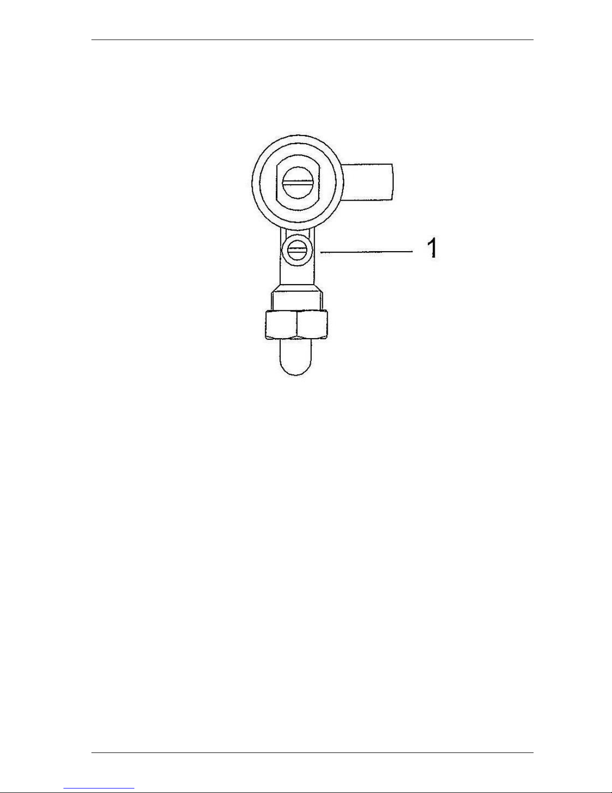
2. Introduce a screwdriver through the hole in the command panel
checking that it is the right type for adjusting the screw (1) (Fig. 8.3).
Page 27
8. MAINTENANCE
ASADOR 5G – 10G – 15G – 20G – 30G – 40G
25
Turn it in a clockwise direction to decrease the power or in
anticlockwise direction to increase it.
3. When regulation has been completed, put back the knob.
Fig. 8.3
Page 28
8. MAINTENANCE
ASADOR 5G – 10G – 15G – 20G – 30G – 40G
26
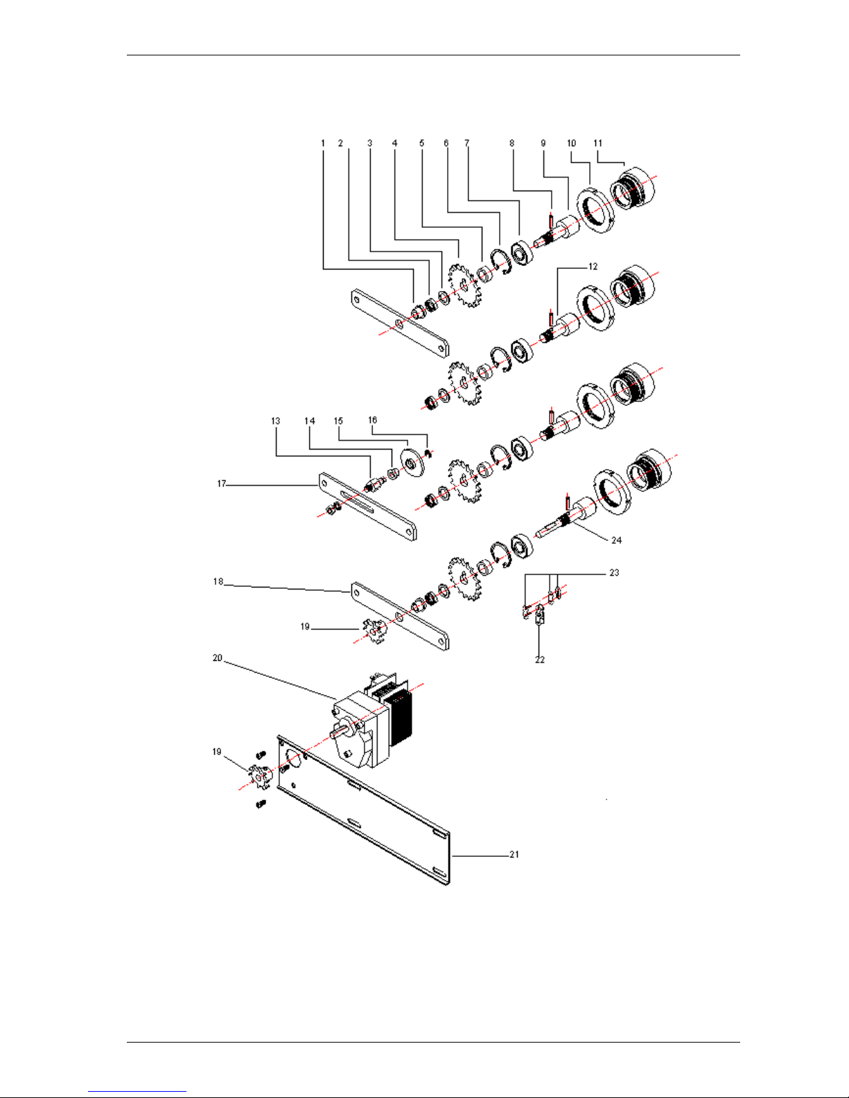
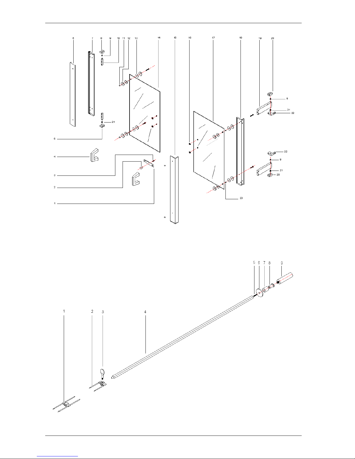
8.4 Exploded Diagrams
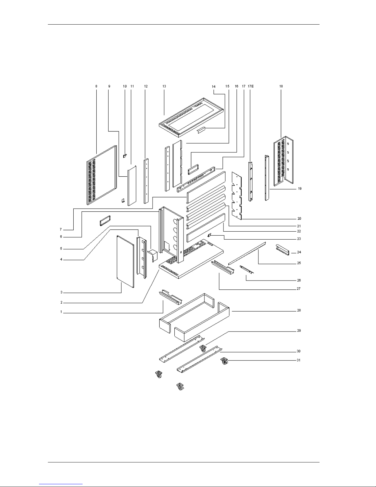
Exploded diagrams of the equipment are shown below with reference to
each component making it simpler to find the cause of faults and if
necessary to substitute damaged parts.
Fig. 8.4 Structure
Page 29
8. MAINTENANCE
ASADOR 5G – 10G – 15G – 20G – 30G – 40G
27
Fig. 8.5 Transmission
Page 30
8. MAINTENANCE
ASADOR 5G – 10G – 15G – 20G – 30G – 40G
28
Fig. 8.6 Glass
Fig. 8.7 Spits and forks
Page 31
8. MAINTENANCE
ASADOR 5G – 10G – 15G – 20G – 30G – 40G
29
Fig. 8.8 Fig. 8.8 Spit burner group
8.5 Wiring diagram
Wiring diagram in use with all the Asador G models
Fig. 8.9. Wiring diagram for the connection of 230V -1N -50Hz electric motors
Page 32
9. DECOMISSIONING AND DEMOLITION
ASADOR 5G – 10G – 15G – 20G – 30G – 40G
30
9. DECOMISSIONING AND DEMOLITION
Before proceeding with the decommissioning disconnect the electrical
supplies to the equipment and any other connections there may be and
then move the modules using suitable means such as: forklift trucks,
hoists, and so on.
The ovens are made up of the following materials: stainless steel, coated
steel, glass, ceramic material, rock wool and electrical parts.
For the purposes of demolition therefore the materials have to be
separated in observance with the norms in force in the place where the
machine is being dismantled.
In any case, do not dispose of these directly into the environment.
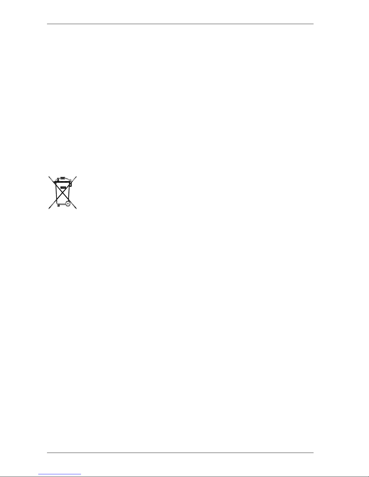
Separate collection. This product must not be disposed of
with normal household waste. Local RAEE regulations may
provide for separate collection of this kind of product.
 Loading...