

Page 1

OWNERS MANUAL
SL27
652792
Page 2

CONTENTS
Section Index
Specifications ...........................................................................................................................1
Important Safeguards ...............................................................................................................2
General Diagrams ....................................................................................................................3 - 4
I. Unpacking .............................................................................................................................5
II. Information About Laminating Film .......................................................................................5
III. Operating
A. Control Panel ...............................................................................................................5
B. Loading Film: 1” Mandrel .............................................................................................6
C. Threading Film .............................................................................................................7
D. Laminating ...................................................................................................................8
E. Supply Roll Tension Adjustment ..................................................................................8 - 9
V. Maintaining the SL27
A. Care and Cleaning .......................................................................................................9
B. Specific Troubleshooting Guide ...................................................................................10
C. Removing a Wrap Around ...........................................................................................10 - 11
Appendix A
Replacing the Hand Held Cutter Blades ..........................................................................11
Warranty ...................................................................................................................................12
Parts List ...................................................................................................................................13
Page 3

SPECIFICATIONS
Height .................................................................................. 15”
Width ................................................................................... 34”
Depth (with feed tray ) ......................................................... 20”
Net Weight ........................................................................... 66 lbs.
Shipping Weight .................................................................. 72 lbs.
Capacity............................................................................... 27”
Electrical .............................................................................. 120V AC, 60Hz, 1400w
1
Page 4

IMPORTANT SAFEGUARDS
• Read all the safety and operating instructions before connecting or using this unit.
• Retain this notice and the owners manual for future reference.
• Adhere to all warnings and operating instructions.
• Do not use this unit near water (e.g. near a bathtub, etc.)
• The wearing of ties or jewelry while operating a laminator may be hazardous to the operator.
• Warning: Do not touch hot surfaces such as heat shoes and heat rollers.
• This unit should be installed so that its location or position does not interfere with its proper ventilation.
For example, it should not be situated on a bed, sofa, rug or similar surface that may block the ventilation openings; or placed in a built-in installation, such as bookcase or cabinet or against the wall, that
may impede the flow of air through its ventilation openings.
• This unit should be situated away from heat and air ventilation systems such as radiators, heat registers, stoves, etc.
• This unit should only be connected to a power supply outlet of the voltage, amperage and frequency
marked on its serial tag.
• For 120 volt machines the socket outlet shall be installed near the equipment and be easily
accessible.
• The power supply cord should be routed so that it is not likely to be walked upon or pinched, especially
near the plug, convenience receptacles, or where the cord exits from the unit.
• Unplug the machine during any machine repairs.
• Clean unit only as recommended in this instruction manual.
• Make sure to remove the Feed Table before reversing the machine!
• Care should be taken so that objects do not fall, and liquids are not spilled, into the enclosure through
any openings.
• Caution: The Cutter blade is extremely sharp. Please handle carefully and dispose of properly.
2
Page 5

GENERAL DIAGRAMS
The SL27, offers a reverse feature. They are designed to laminate a variety of materials using up
to 27” laminating film. The SL27 laminator is set at a fixed speed and can be reversed by the
push of a button. Tension Adjusting Knobs (L) are conveniently located on the Supply Mandrels (K)
on the right side panel for easy access. A Control Panel (G) is located on the Left Housing
(E), with a Motor Stop/Reverse switch (B), and a Heat On/Off Switch (A).
A
B
C
The Feedtray (H) and Feed Guide (I) provide a smooth, durable paper path and the Heat Guard (F)
protects hands from hot surfaces inside. Teflon coated Heat Shoes (J) minimize friction. The Cutter (D)
cuts and trims your laminated documents and the Keyswitch (C) prevents unauthorized usage.
3
Page 6

GENERAL DIAGRAMS
D
M
F
E
N
J G H K L I
4
Page 7
I. Unpacking
Remove the laminator from its box by grasping the housings and pulling up. Do not use rollers or shafts
as handles - this could cause damage. Choose a location for the laminator that is clean, well-lit and draft
free. Make sure it is not in the path of any fans, room air conditioners, or positioned too close to the wall.
The laminator comes to you ready to load the film onto the supply mandrels, thread the film through the
machine, and install the feedtable.
II. Information About Laminating Film
Laminating film is made up of two layers: a glossy layer which gives the lamination its strength, clarity and
rigidity, and a dull or matte side which is heat activated and serves as the “glue” to bond the film to the
product being laminated. Once heated, small amounts of the “glue” side can stick to the heat shoes and
rollers and must be periodically cleaned from the laminator.
Laminating film is available in a variety of different lengths, and thicknesses. The SL27 Laminator
is designed to use 1.5 mil (#150), and 3 mil (#300), film thicknesses.
III. Operating
A. Control Panel
The control panel is located on the left side of the laminator. This panel is used to control the various
machine functions listed below.
Heat (A,M,N)
The temperature can be turned either “on” or “off” using the the heat switch (A) which is located on the
control panel. The heat can be controlled manually using the heat control knob (N) located on the left
housing (E). A thermostat (M) is also located on the left housing (E) and provides the current temperature
of the laminator. Note: depending on room conditions and desired set point, it will take between 20 and
30 minutes for the laminator to heat up to desired temperature.
Motor (B)
To stop the motor, press the “Stop/Reverse” switch in the “Stop” (nuetral) position. To start the motor,
press the “Stop/Reverse” switch in the “Fwd” location. To reverse the motor, press the “Stop/Reverse”
switch in the “Rev” location. The motor will remain in reverse as long as the button is depressed.
Additional Features
Keyswitch
The keyswitch (located just below the control panel) locks out the motor, allowing the machine to remain
heated; yet, preventing unauthorized usage when in the locked position.
5
Page 8
B. Loading Film: 1” Mandrel (K)
Unpack the upper and lower supply mandrels. The upper and lower mandrels are
different. The word “TOP” is stamped on
the shaft of the upper mandrel and the
word “LOW” is stamped on the shaft of the
lower mandrel. The ends of each mandrel
are also different. The “hanger” end fits in
the bracket on the left side of the laminator.
The “slot end” fits into the tension adjuster
on the right side.
Slide the film roll onto the mandrel by rotating the mandrel in the opposite direction of
the gripper points, leaving equal lengths of
mandrel sticking out of each end. The film
roll will slide over the gripper, which will
keep the roll from turning on the shaft.
LOW
TOP
Load the mandrel on the laminator by inserting the slot end of the mandrel into the
tension adjuster on the right side and then
lowering the hanger end into the bracket
on the left side.
6
Page 9
C. Threading the Film
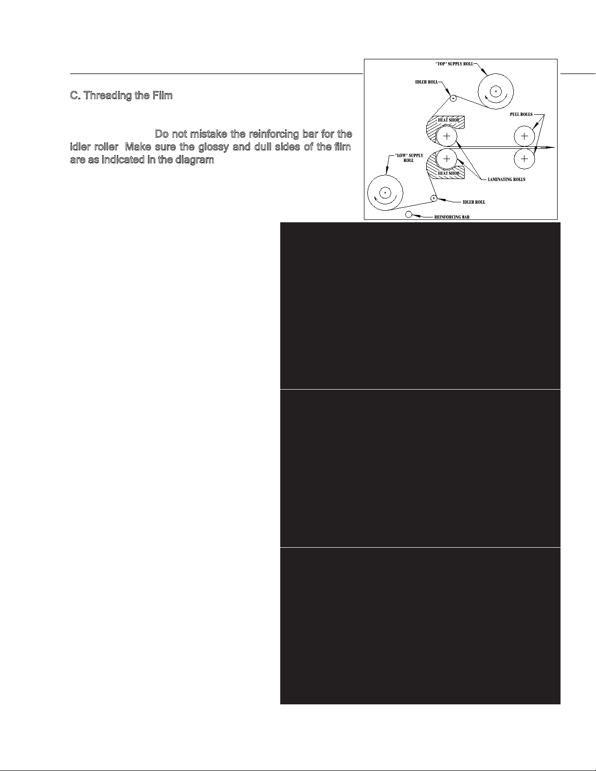
Remove the feed tray and the heatguard. Thread the film as
shown in the figure on the right. Pull the film around the idler
rollers as shown.
Do not mistake the reinforcing bar for the
idler roller. Make sure the glossy and dull sides of the film
are as indicated in the diagram. Position the threading board
provided.
Turn power and keyswitch to on.
D
U
L
L
S
I
D
S
E
H
I
N
Y
S
I
D
E
E
D
I
S
L
L
U
D
E
D
I
S
Y
N
I
H
S
Start the motor by pressing the “Fwd” button. Feed the threading board and film in
between the heat shoes. This will pull the
film through the rollers until it comes out
the back of the laminator.
Slide the top and bottom film rolls from side
to side on the mandrels so that the film is
perfectly aligned top and bottom (Note:
overlap will cause the film to deposit residue on the heat shoes and rollers, so this
procedure is critical). Replace feed tray
and heat guard.
7
Page 10
D. Laminating
After the machine is loaded with film (see
B. Loading Film: 1” Mandrel) and threaded
(see C. Threading the Film), it is ready to
laminate. Ensure that the laminator has
reached the preset temperature. This will
be indicated by the ready light being illuminated. Place document on the feedtable
and align with the feedguide to assure
straight and even lamination. Start the motor with the “Fwd” button and if necessary,
adjust the supply roll tension (see E. Supply Roll Tension Adjustment). With both
hands, guide the document into the throat
of the laminator. While the document is
pulled into the laminating rollers, keep document flat on the feedtable while applying
a slight back pressure. As the document
exits the rear rollers, allow 3” to 6” of film to
clear the rollers at the end of your document and turn the motor switch to stop. Using the hand held cutter, hold tension on the laminated document and slice through the film to release the document. Multiple
documents can be run successfully if desired and cut at a later time.
E. Supply Roll Tension Adjustment (L)
Top and bottom supply rolls should have about the same tension. By turning the top roll with one hand,
and the bottom roll with the other hand, it can be determined if one of the rolls is tighter than the other.
Note: Too much tension can destroy film,
documents, and damage the machine.
Adjust the tension to the minimum amount
required. Do this by loosening the tension
knobs until there is no tension on the film.
With the machine threaded and at operating temperature, turn the motor switch to
forward. Tighten the adjusting knobs only
until the wrinkles in the film are removed.
8
Page 11

Note: As the diameter of the film roll decreases, tension should be reduced.
To increase tension, turn the adjusting knob clockwise. To decrease tension, turn the knob counterclockwise. If the tension is not equal top and bottom, the laminated product will curl. If the material curls
it comes out of the machine, the top roll is probably tighter than the bottom. If it curls
roll is probably tighter.
Note: Make sure the black disks are flat against the sidepanel. They should be rotating, both top and bottom, while film is feeding.
V. Maintaining the SL27
A. Care and Cleaning
In the normal course of operating the SL27, dirt and adhesive will accumulate on the heat shoes
and rubber rollers (Laminating produces static electricity which attracts airborne dust and dirt). Regular
inspection and cleaning will assure that this does not become a problem.
Never use hard, sharp, or abrasive items to clean the heat shoes. The shoes are coated with a non-stick
surface that could easily be damaged. Likewise, do not use sharp metallic objects or steel wool to clean
the rubber rollers. Any scratches, indentations, or marks left on the rollers will appear on the laminated
product.
To clean the shoes and rollers, use a clean, lint-free cloth. Some suggested solvents are Poly-Off®, rubbing alcohol(isopropyl), fingernail polish remover(with acetone), and Goof-Off® spray.
down, the bottom
up as
9
Page 12
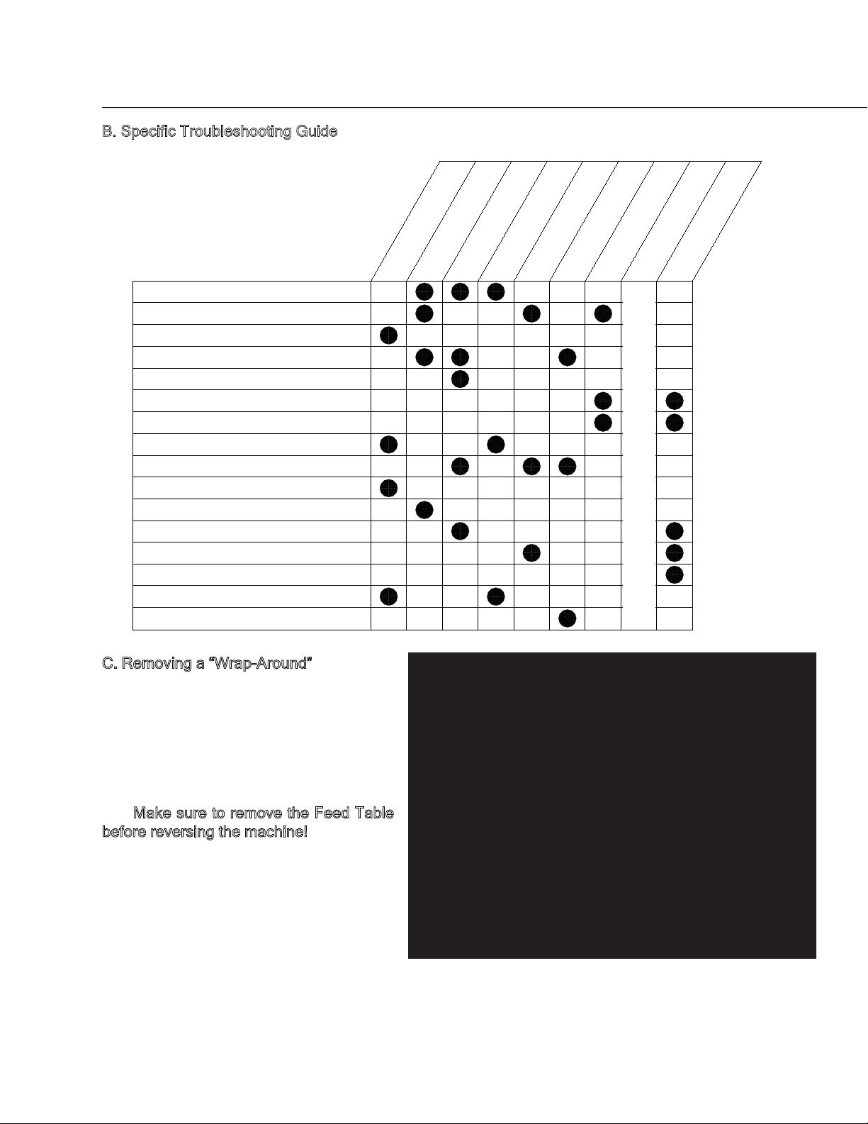
B. Specific Troubleshooting Guide
Wrinkles on Film (side to side)
Wrinkles on Film (lengthwise)
Plastic not bonding
Bubbles or Blisters
Impressions on product
Squeaking sounds
Film narrowing on shoes
Film wrinkling on shoes
Continuous blemish
Cloudy film
“Orange Peel” Finish
Film sticks to rollers
Film sticks to shoes
Film won’t stay aligned
No seal on edges
Poor seal - one side only
Increase Heat
Worn, Dirty, Or
Decrease Heat
Increase Tension
Dirty Heat Shoes
On Supply Rolls
Damaged Rollers
Moist Or
Decrease Tension
Coated Product
On Supply Rolls
Diagram
Check Threading
C. Removing a “Wrap-Around”
A “wrap-around” occurs if the film exiting
the rear rollers curls around one of them
causing the laminate to wind around the
roller.
If the wrap-around is not severe, simply
use the reverse feature and back the film
Make sure to remove the Feed Table
out.
before reversing the machine!
For extreme wrap-arounds (i.e. when plastic and/or product have wrapped around
the rubber rollers several times) follow this
procedure:
10
Page 13
Shut the machine off! SL27’s have set screws at both ends of each laminating and pull roller. With
the use of a 3/32 hex key, loosen all four set screws on the pull rollers. Cut the plastic between the laminating and pull rollers, grab the loose end and pull. The rollers will rotate freely on the roll shafts and the
“wrap-around” will easily unwrap. Tighten all the set screws and rethread the film.
Appendix A
Replacing the hand held Cutter Blades.
The hand held cutter blade can be replaced
by removing the small screw on the back of
the cutter, then removing the cutter back.
Caution: The cutter blade is extremely
sharp. Please handle carefully and dispose of properly. Remove and discard the
old blade. Re-install cutter back and screw.
Caution: Do not over tighten screw.
11
Page 14

LIMITED WARRANTY
Dealer, warrants to the original consumer purchaser that each new SL27 Laminator which proves
defective in materials or workmanship within the applicable warranty period will be repaired or, at our
option, replaced without charge upon its return as outlined below. The applicable warranty shall be one
year from date of purchase. “Original consumer purchaser” means the purchaser who first purchased the
product covered by this warranty other than for purpose of resale.
Liability for breach of any warranty express or implied shall be limited to the repair or replacement, at
dealer, option, of the defective item. Dealer shall not be liable for damages arising out of, or in connection with the use or performance of any product. Any implied warranty shall be limited in duration to the
duration of this warranty. Some states do not allow limitations on how long an implied warranty lasts for
the exclusion or limitation of consequential damages, so the above limitation may not apply to you.
There are no consumer serviceable parts in the SL27 Laminator. If you require service under this
Warranty, contact your dealer to obtain Return Authorization (RA), pack the product in its original packaging (or request the same from Technical Service when requesting the RA), and include a description of
the malfunction and proof of date of purchase. Technical Service will arrange for the SL27 Laminator to
be picked up by a freight company. Failure to return in original packaging could void this warranty.
The
Warranty extends to and is enforceable only by the original consumer purchaser, and only for the
period which the product remains in the possession of the original equipment purchaser. This Warranty
does not cover any defect or malfunction due to the use of faulty non- SL27 Laminator materials,
This Warranty gives you speci fic legal rights and you may have other rights, which vary, from state to
state.
.ecnanetniam yrassecen dna elbanosaer edivorp ot eruliaf ro ,enihcam eht fo esuba ro esu elbanosaernu
12
Page 15

DRY LAM
SL27
Parts List
eP yt
QnoitpircseD#metI r U/M
907002P HAND HELD SLITTER,Drylam 1.0 EA
707583 RIGHT HOUSING, Gray, Drylam 1.0 EA
611077
707284 LEFT FEED GUIDE, BLACK POWD 1.0 EA
601345 SCREW,8-32X1/2 WASHER FACE 1.0 EA
800731 THREADING DIAGRAM 25" MINIK 1.0 EA
601090 SCREW,6-32X3/16 PAN HEAD 2.0 EA
801205 SPROCKET 25B23 5/16, 10-32 1.0 EA
801206 SPROCKET 25B20 12.5mm 10-32 1.0 EA
801207 SPROCKET 25B19 12.5MM 10-32 1.0 EA
600350 SCREW,10-32 X 3/8,SET CONE 3.0 EA
654095 BUSHING-UPPER ROLL AV DELRI 2.0 EA
802461 KNOB,BLCK CAP Temp Adjuster 1.0 EA
707740 LEFT HOUSING, Gray, Drylam 1.0 EA
604815 WASHER #8 EXT STAR LOCK 3.0 EA
601090 SCREW,6-32X3/16 PAN HEAD 2.0 EA
620131 WIRE CLAMP,3/16",CCL187-170 2.0 EA
707856 Switch MNTG BRACKET, MK2 G3 1.0 EA
600966 SCREW,1/4X1.25,SHOULDER,10- 4.0 EA
6-19X5/8 PLASTITE 48-2 THRE 8.0 EA
.1RETEMOMREHT LRA6054A
.2CHS 5.1X23-01,WERCS117006
AE0.13-G LAUNAM NOITAREPO297256
AE0.1"52 ,DRAOB GNIDAERHT060356
AE0.1"72 ,ETOKINIM ,XOBMAOF089256
AE0.1TENGAM RETTILS400707
AE0.1DRAUGTAEH 72 LRA7393A
AE0.1"72 ,LRA ,ELBAT DEEF509707
AE0.1NAMRENNIT 23-8 ,TUN043306
AE0.1AERA TOH,LACED155008
AE0.1LEBAL GNINRAW NOISNET096008
AE0.1ETOKINIM ,NIAHC110809
AE0.1lebaL dnuorG855008
AE0.1LEBAL DRAUG TAEH 2G230508
AE0
AE0.2DAEH NAP 4/1X23-8,WERCS511106
AE0.5M-M1 TLP "8/7 3 ,EIT ELBAC521026
AE0.1NAP LIHP ,HR 2/1x23-6211106
AE0.5DAEH NAP 4/1X23-6,WERCS001106
AE0.12KM ,TEKCARB HCTIWSYEK449707
AE0.12G2KM,LEBAL HCTIWSYEK229707
AE0.1,HCTIWSYEK719096
AE0.1tekcoS senoJ - gulP paC315016
AE0.13G2KM,LEBAL hctiwS,3G110807
AE0.1HCTIWS THGIL 20020155A
AE0.1 HCTIWS EVIRD 20024155A
AE0.1KCAP ERIW2274A
AE0.2CHS 4/1-1 X 23-01,WERCS080006
AE0.24/3X4/1 RECAPS040016
AE0
AE0.2LEETS 230.1X4/1 RECAPS620016
AE0.3M-M1 TLP "8/7 3 ,EIT ELBAC521026
13
Page 16

Dry Lam
SL27
eP ytQnoitpircseD#metI r U/M
707901 UPPER ROLL SHAFT ARL-27" 2.0 EA
707902 LOWER ROLL SHAFT ARL-27" 2.0 EA
600680 SCREW,10-32X1/2 BUTTON HEAD 4.0 EA
801939 POWER CORDS 16-3 MILLER #E9 1.0 EA
620112 STRAIN RELIEF,HEYCO 3213/3 1.0 EA
620045 RING CONNECTOR,B-237-08X 1.0 EA
620005 CONNECTOR, BLUE/ETC# BB-526 2.0 EA
620169 BLACK SLEEVING,3/8",NYLON, 0.5 FT
601090 SCREW,6-32X3/16 PAN HEAD 2.0 EA
927731P UPPER HEATSHOE ASSEMBLY G-2 1.0 EA
620000 CONNECTOR, RED/ETC# AA-5261 2.0 EA
A4785 27" LOWER CLASSROOM HEATSHO 1.0 EA
A4599 8-32 x 5/8 HEX WASHER THREA 1.0 EA
927721P LOW HEAT SHOE ASSEMBLY 27" G-3 1.0 EA
620000 CONNECTOR, RED/ETC# AA-5261 2.0 EA
F2.38OH 8# GNIVEELS DER561026
707662 UPPER AND LO HEAT SHOE ARL 1.0 EA
A4735 POLYOLEFIN SHRINK TUBING 1/ 1.0 EA
A4599 8-32 x 5/8 HEX WASHER THREA 1.0 EA
907411UP UPPER SUPPLY ROLL SA,1"-27" 1.0 EA
707685 1" SUPPLY ROLL PLUG - ARL,S 1.0 EA
707706 1" SUPPLY ROLL TUBING ARL 2 1.0 EA
707710 TORSION SPRING 1" EXTRUSION 1.0 EA
907411LP LOWER SUPPLY ROLL SA,1"-27" 1.0 EA
707685 1" SUPPLY ROLL PLUG - ARL,S 1.0 EA
707706 1" SUPPLY ROLL TUBING ARL 2 1.0 EA
707710 TORSION SPRING 1" EXTRUSION 1.0 EA
707415 FRICTION STUD MOLDED - OEM 2.0 EA
707405 LEATHER WASHER, 1" AV-OEM 2.0 EA
802160 COMPRESS SPRING LC-098K-00- 2.0 EA
A3998 ARL TENSION ADJUSTMENT KNOB 2.0 EA
604955 WASHER .265X.500X.015 THICK 4.0 EA
AE0.4LLOR REBBUR "72108056
AE0.4RENIATER GNIHSUB ,PILC741807
AE0.1ROTOM6964A
AE0.4KCOL TILPS 4/1 REHSAW048406
TF5.08OH 8# GNIVEELS DER561026
AE0.2DAEH NAP 4/1X23-8,WERCS511106
AE0.1TEKCARB TATSOMREHT8764A
AE0.1TATSOMREHT8664A
TF8.28OH 8# GNIVEELS DER561026
AE0.1NOISURTXE EOHSTAEH 728554A
AE0.1V021,"72,W056,RETAEH830208
T
AE0.1V021,"72,W056,RETAEH830208
AE0.2S24DMSG,TEVIR004406
AE0.1GULP "D" LLOR YLPPUS "1096707
AE0.2S24DMSG,TEVIR004406
AE0.1GULP "D" LLOR YLPPUS "1096707
AE0.2MEO - VA ETALP NOITCIRF604707
AE0.1RAB GNICROFNIER ,LEBAL655008
AE0.2"72 LLOR RELDI REWOL709707
14
Page 17

Dry Lam
SL27
eP ytQnoitpircseD#metI r U/M
802155 PRESSURE SPRING, MINIKOTE 2.0 EA
707211 PRESSURE ADJUST SCREW 2.0 EA
605021 WASHER,ZINC,.203X.625X.016 2.0 EA
805031 MANDREL COLOR CODE LABELS 1.0 EA
654095 BUSHING-UPPER ROLL AV DELRI 2.0 EA
707939 PRESSURE & HEAT SHOE BRACKE 2.0 EA
654090 BUSHING-LOWER ROLL AV DELRI 2.0 EA
654090 BUSHING-LOWER ROLL AV DELRI 4.0 EA
604465 RIVET,SD64BS,"POP" BRAND 8.0 EA
A5847 ARL TERMINAL BLOCK NUMBERED 1.0 EA
AE0.4SLEWOD LLOR RELDI260707
AE0.1LEBAL DRAUG TAEH 2G230508
AE0.40852 TEEF REBBUR779108
AE0.2CHS 8/5 X 23-01,WERCS550006
AE0.1005-526BS GNIHSUB ERIW034026
AE0.1005-526BS GNIHSUB ERIW034026
AE0.20852 TEEF REBBUR779108
AE0.2CHS 8/5 X 23-01,WERCS550006
AE0.2DAEH NAP 8/5X23-8,WERCS031106
AE0.1sisahC etokiniM "72569707
15
 Loading...