

Page 1
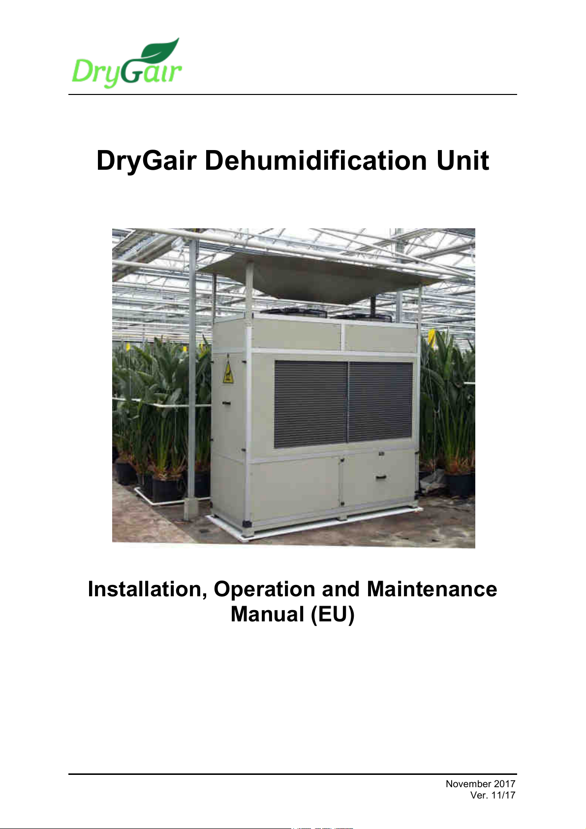
DryGair Dehumidification Unit
Installation, Operation and Maintenance
Manual (EU)
November 2017
Ver. 11/17
Page 2
: drygair.energies
DryGair Energies Ltd. — www.drygair.com
8 Hamanofim St., Herzliya Pituach 46733
Tel.: 972-9-7730980, Fax: 972-9-7730989
Proprietary and Confidential
Copyright © 2017 by DryGair Energies Ltd.
All rights reserved. No part of this manual may be reproduced or copied in any form by any means-
graphic, electronic, or mechanical, including photocopying, typing or information retrieval systems-
without written permission of DryGair Ltd.
DryGair Energies Ltd.
ii
Page 3
DryGair Dehumidification Unit
Table of Contents
TABLE OF CONTENTS
1. INTRODUCTION ______________________________________ 1
2. SAFETY _____________________________________________ 3
3. UNIT OVERVIEW _____________________________________ 7
4. INSTALLATION ______________________________________ 10
5. UNIT PARTS AND COMPONENTS ______________________ 24
Ver. 11/17
iii
Page 4
Table of Contents
6. UNIT OPERATION ___________________________________ 33
7. MAINTAINING THE UNIT ______________________________ 40
8. TROUBLESHOOTING AND REPAIRING THE UNIT _________ 43
9. APPENDICES _______________________________________ 45
10. COMMENTS AND NOTES _____________________________ 62
DryGair Energies Ltd.
iv
Page 5
DryGair Dehumidification Unit
List of Figures
LIST OF FIGURES
Figure 2-1. High Voltage warning label _________________________________________ 5
Figure 2-2. Hearing Protection required label ____________________________________ 5
Figure 2-3. Hot Surface caution label ___________________________________________ 5
Figure 2-4. Lift from Here notice _______________________________________________ 5
Figure 2-5. DryGair Identification label __________________________________________ 6
Figure 3-1. DryGair unit (front view) ____________________________________________ 9
Figure 3-2. DryGair unit (rear view) ____________________________________________ 9
Figure 4-1. Transferring the unit ______________________________________________ 19
Figure 4-2. Water drain outlet ________________________________________________ 22
Figure 4-3. Electrical switchboard and grid terminal block __________________________ 23
Figure 5-1. Temperature and humidity sensor ___________________________________ 24
Figure 5-2. Sensor unit _____________________________________________________ 24
Figure 5-3. Defrost temperature sensor ________________________________________ 25
Figure 5-4. Electrical compartment ___________________________________________ 26
Figure 5-5. Compressor (front view) ___________________________________________ 29
Figure 5-6. Compressor (rear view) ___________________________________________ 29
Figure 5-7. Oil pressure protector and switches __________________________________ 30
Figure 5-8. Heat exchange compartment _______________________________________ 30
Figure 5-9. Expansion valve _________________________________________________ 31
Figure 5-10. Sight glass ____________________________________________________ 31
Figure 5-11. Blowing fans ___________________________________________________ 32
Figure 6-1. Humidistat controller _____________________________________________ 36
Figure 9-1. Standard unit ___________________________________________________ 46
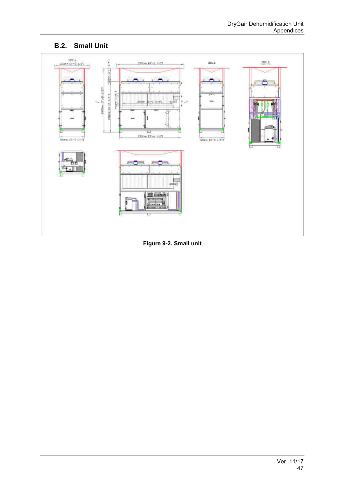
Figure 9-2. Small unit ______________________________________________________ 47
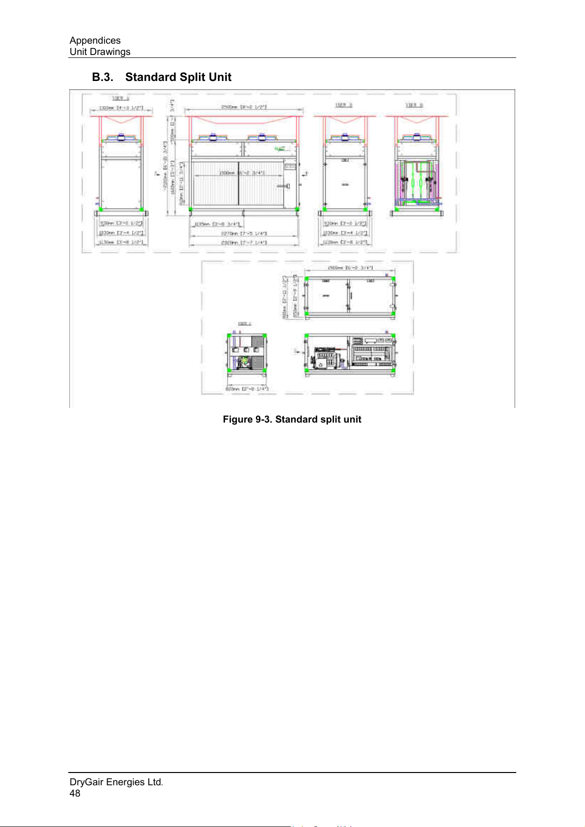
Figure 9-3. Standard split unit _______________________________________________ 48
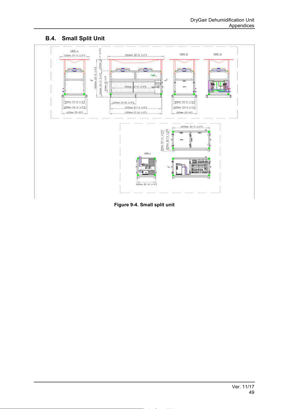
Figure 9-4. Small split unit __________________________________________________ 49
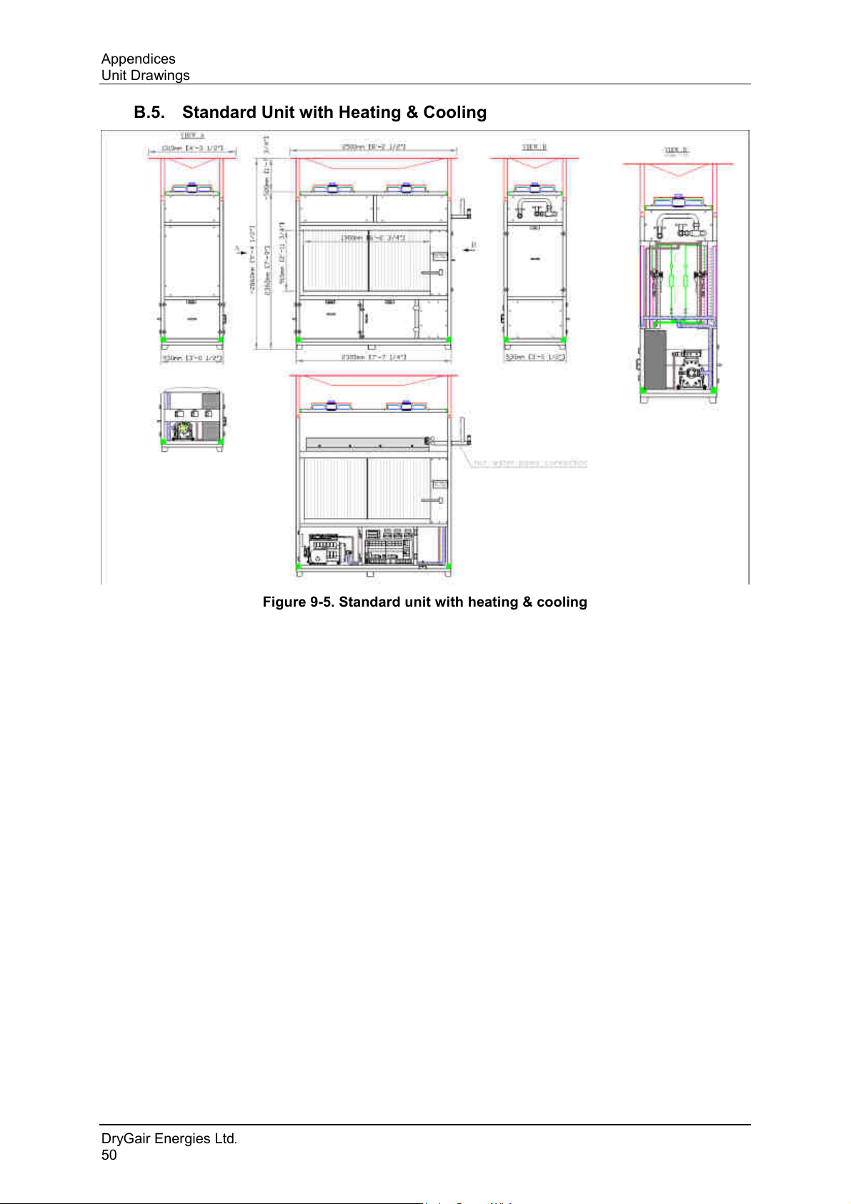
Figure 9-5. Standard unit with heating & cooling _________________________________ 50
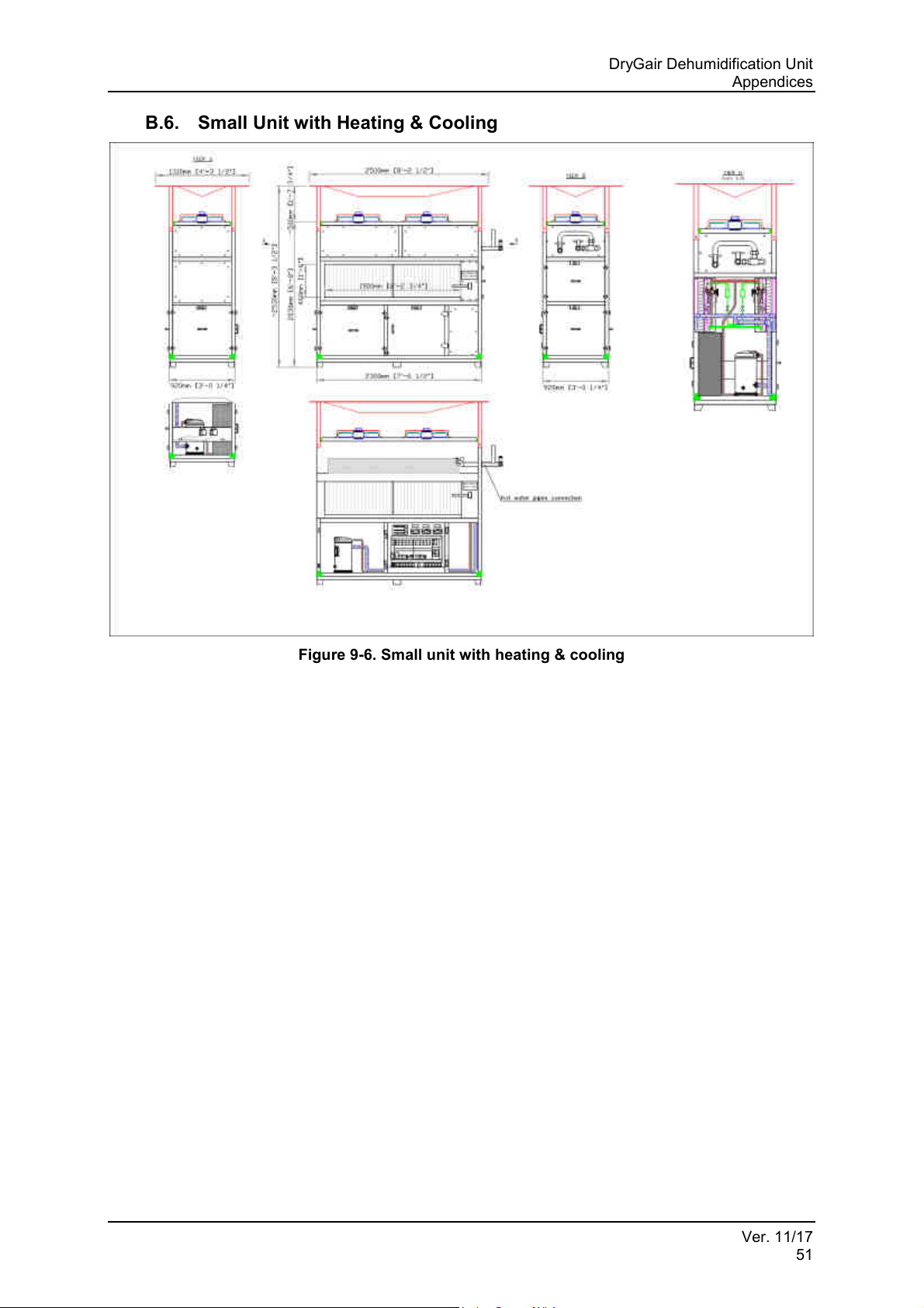
Figure 9-6. Small unit with heating & cooling ____________________________________ 51
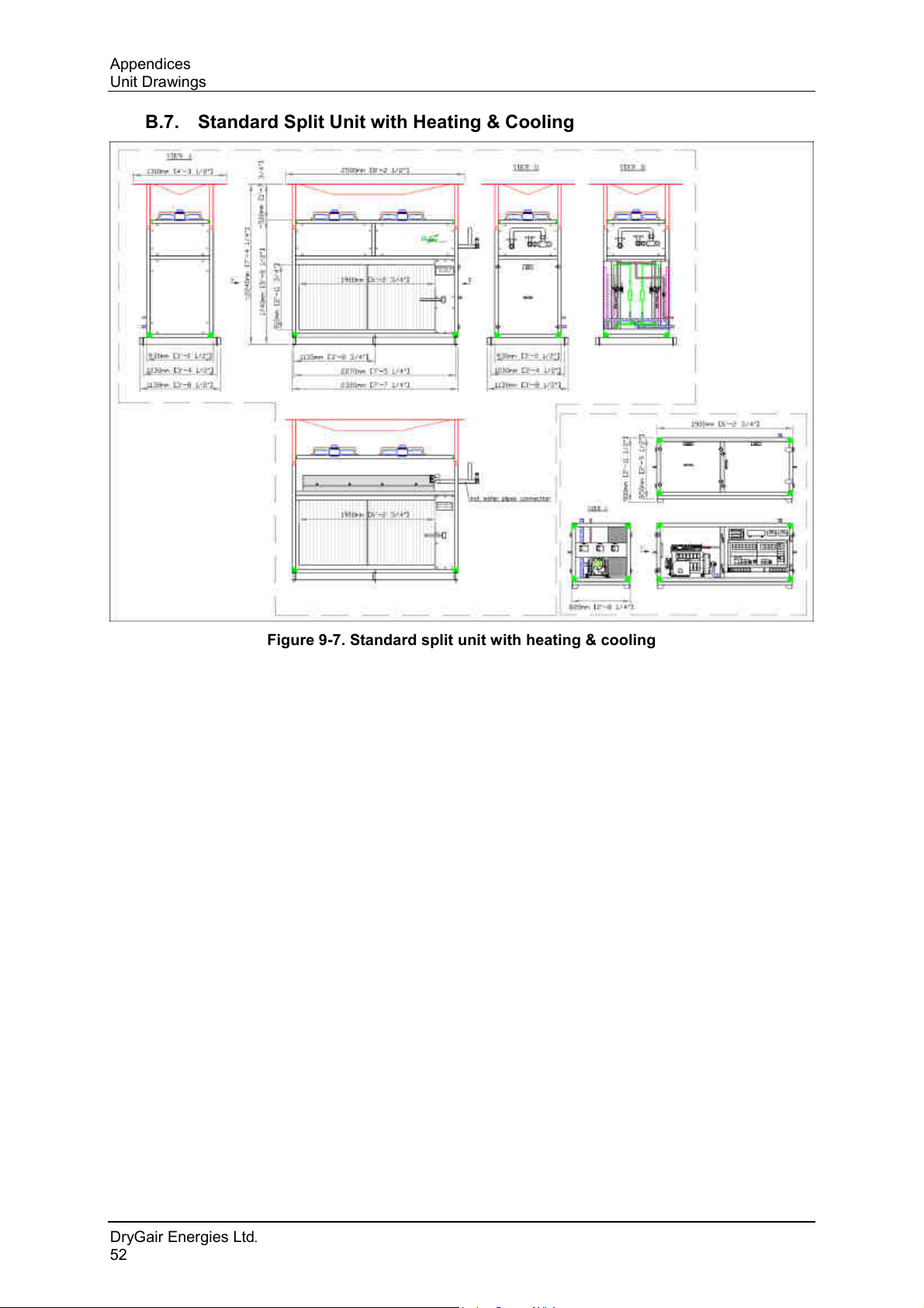
Figure 9-7. Standard split unit with heating & cooling _____________________________ 52
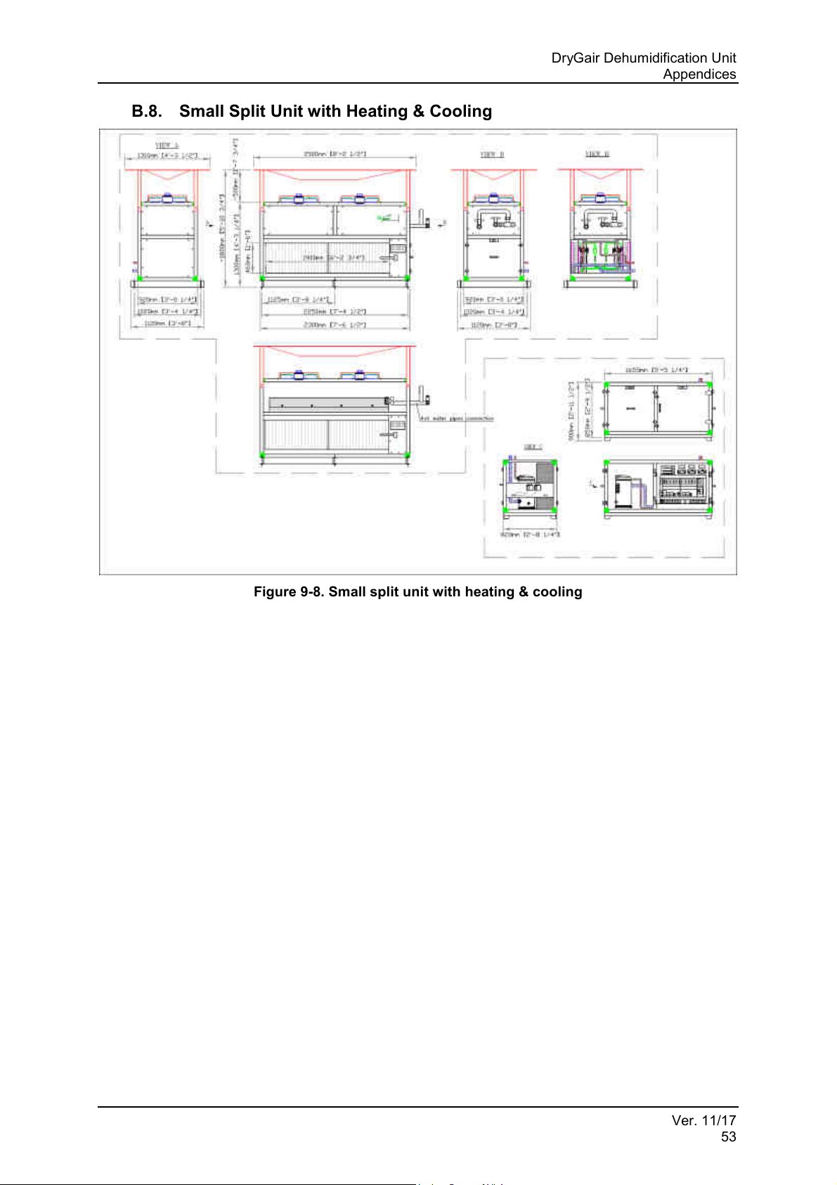
Figure 9-8. Small split unit with heating & cooling ________________________________ 53
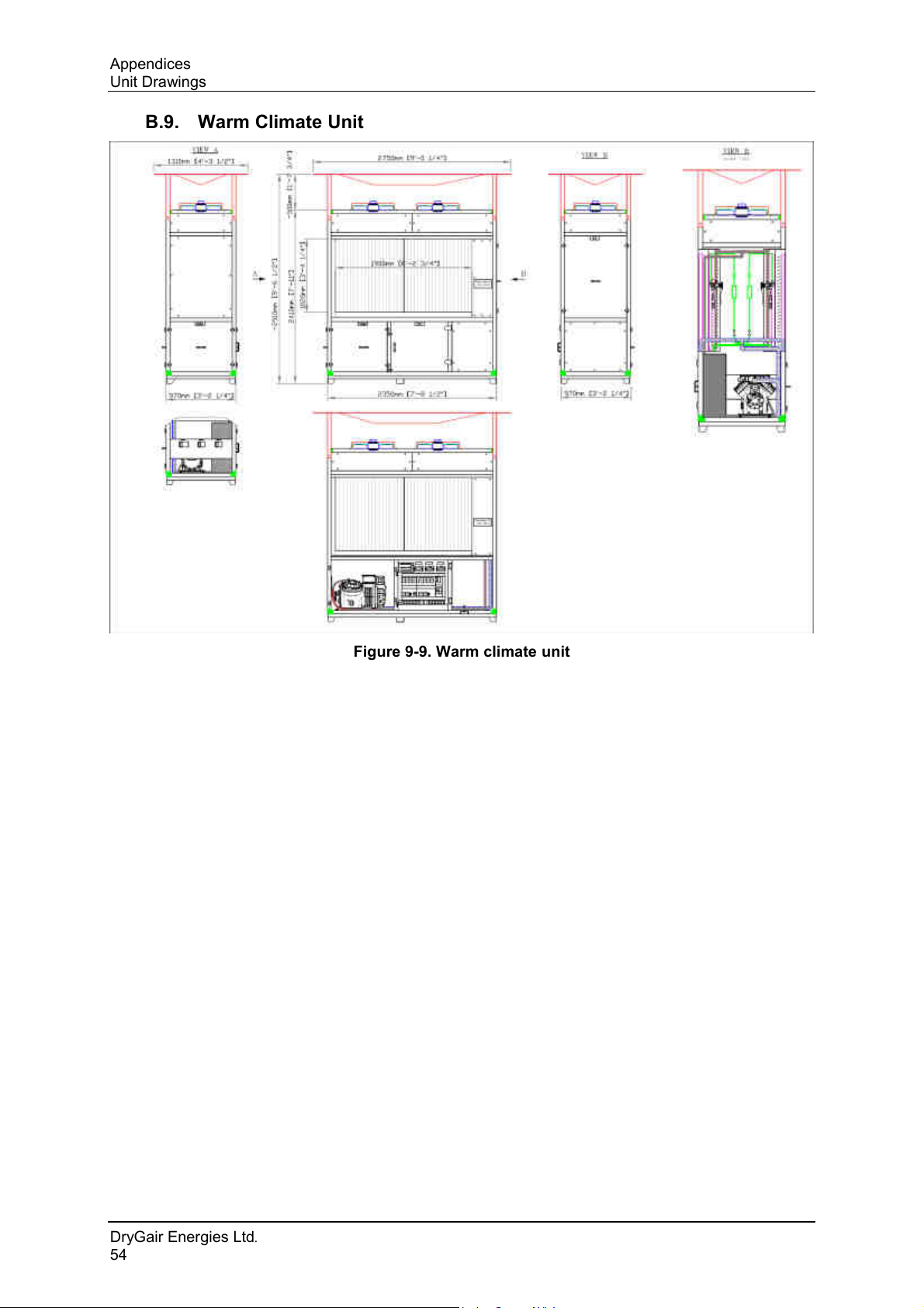
Figure 9-9. Warm climate unit _______________________________________________ 54
Figure 9-10. Four-direction canopy ___________________________________________ 55
Figure 9-11. Air distributor module (4-way canopy) _______________________________ 56
Figure 9-12. One-direction canopy ____________________________________________ 57
Figure 9-13. Air distribution panel ____________________________________________ 58
Figure 9-14. Split unit ______________________________________________________ 59
Figure 9-15. Split unit connecting tubes ________________________________________ 59
Figure 9-16. Air heating option _______________________________________________ 61
Ver. 11/17
v
Page 6
List of Tables
LIST OF TABLES
Table 4-1. Parts and Accessories ____________________________________________ 20
DryGair Energies Ltd.
vi
Page 7
DryGair Dehumidification Unit
Introduction
1. INTRODUCTION
This manual provides instructions for operating the DryGair unit in a correct
and safe way, including installation instructions, maintenance procedures
and unit troubleshooting.
As DryGair continuously develops its machines to their maximum potential,
this manual, though completely up to date when issued, is subject to changes
without notice.
1.1 Before You Begin
Before you begin working with the DryGair dehumidification unit, read the
following
• This manual: the DryGair dehumidification Operation and Maintenance
Manual provides information and procedures for operating the unit, as
well as maintenance, troubleshooting and repair procedures.
▪ The safety instructions.
▪ Conventions: explains the symbols used in this manual.
Before beginning a procedure:
• Read the procedure through to the end. Thorough understanding of the
entire procedure prevents unnecessary loss of time and error.
1.2 Further Information
For further information, contact DryGair at:
Email:
Website: www.drygair.com
info@drygair.com
Ver. 11/17
1
Page 8
Introduction
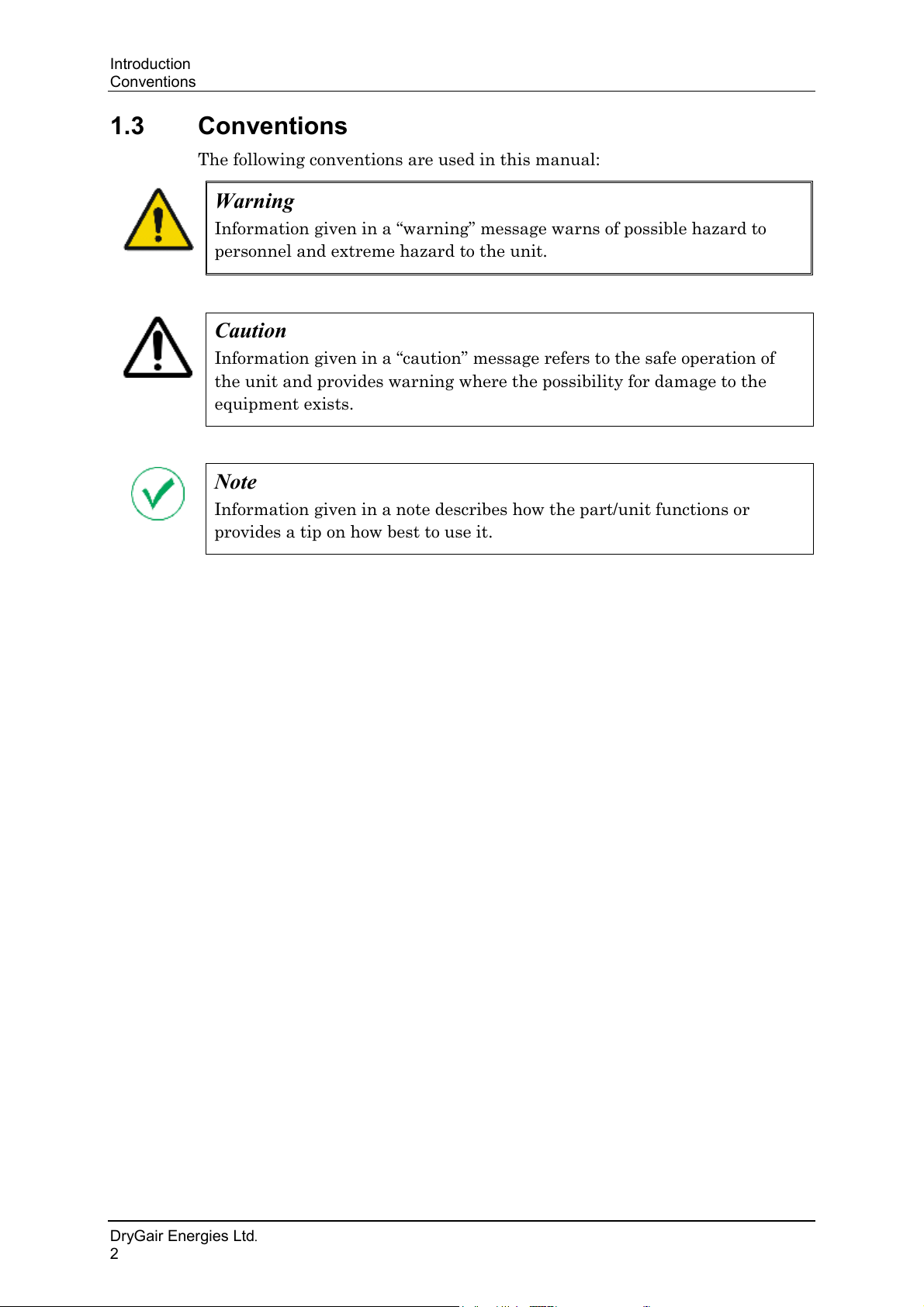
Warning
Information given in a “warning” message warns of possible hazard to
personnel and extreme hazard to the unit.
Caution
Information given in a “caution” message refers to the safe operation of
the unit and provides warning where the possibility for damage to the
equipment exists.
Note
Information given in a note describes how the part/unit functions or
provides a tip on how best to use it.
Conventions
1.3 Conventions
The following conventions are used in this manual:
DryGair Energies Ltd.
2
Page 9
DryGair Dehumidification Unit
Safety
2. SAFETY
DryGair Energies Ltd. believes that the safety of personnel working with and
around the unit is the most important consideration. The DryGair unit is
equipped with all the safety devices necessary to ensure risk-free use under
standard conditions.
Machine installation, maintenance and adjustments must be performed only
by a qualified technician with expert machine knowledge and that has read
this manual.
Before operating the unit or performing maintenance operations, read and be
familiarized with the safety information.
• Obey and follow all warnings and cautions given in this manual.
• Comply with all approved and established precautions for operating
electrical and mechanical equipment.
• Only qualified and authorized personnel should perform maintenance or
repair tasks.
• Verify the power, and any other connected facilities, are turned off and
disconnected before beginning maintenance procedures, part
replacements, or repairs.
• We advise strict observance of the work safety standard as defined by the
authorities in each country.
DryGair cannot accept responsibility for injury to persons or damage to
objects resulting from not observing safety standards.
2.1 Hazards
Danger: Electrical Shock Hazard. High voltage is present at points throughout the
Unit. Contact with high voltage can result in injury or death. Before performing any
operation related to electricity, open the electric compartment cover, switch off the
Main Power switch and switch off the Circuit Breaker. Doing so ensures no voltage
is present.
Danger: Hot Surface Hazard. The heat exchangers and their pipes, and the
compressor may have a high temperature during unit operation. Do not touch the
compressor and the heat exchanger pipes and coils while the unit is operating.
Verify the unit has cooled down before touching them.
Danger: Bodily Injury Hazard. Be careful not to drop any of the unit parts.
Dropping the Covers might cause bodily injury or damage to the parts.
Ver. 11/17
3
Page 10
Safety
Operation Safety Notes
2.2 Operation Safety Notes
The following safety practices must be complied with:
• CAUTION and WARNING notices posted on the machine and safety
notes in this manual.
• Ensure that all control panels and electrical panels are covered.
• Do not start the unit if any of the safety covers is missing.
• MOVING PARTS – Do not touch the fans during unit operation.
• Do not permit smoking or food in the working area.
• Personnel operating the unit must not remove covers or panels.
• Although the electrical compartment is closed by a door, operator access
to the compartment is strictly forbidden without explicit authorization.
• Ensure that all personnel operating the unit know where the main power
switch is located and what to do in case of electrical emergency.
• Locate approved types of fire extinguishers near the equipment.
2.3 Maintenance Safety Notes
Only authorized personnel are permitted to perform maintenance and repair
tasks. Before performing such a task, read the instructions to ensure you
understand them and that the required precautions and tools are available.
• For high mounted maintenance procedures, use a stable ladder to avoid
high fall injuries.
• To avoid getting caught in moving parts do not lubricate, repair or adjust
the machine while in operation, unless expressly written in the manual.
Stop the machine according to the machine stopping procedure before
lubricating or performing other maintenance tasks.
• Secure electrical wires and cables to prevent damage.
• The protecting doors and covers should not be opened during machine
operation.
• Replace all safety shields after completing set-up, troubleshooting and
maintenance procedures.
DryGair Energies Ltd.
4
Page 11
DryGair Dehumidification Unit
Safety
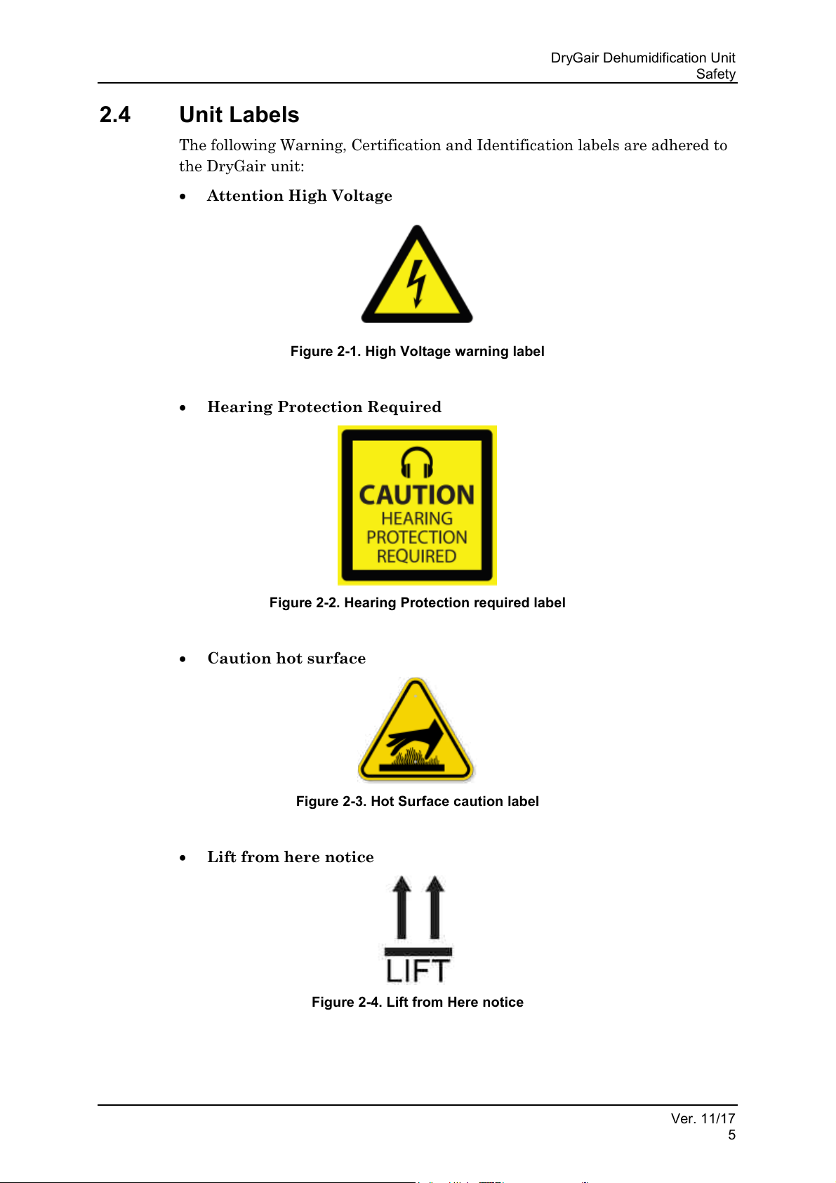
2.4 Unit Labels
The following Warning, Certification and Identification labels are adhered to
the DryGair unit:
• Attention High Voltage
Figure 2-1. High Voltage warning label
• Hearing Protection Required
Figure 2-2. Hearing Protection required label
• Caution hot surface
Figure 2-3. Hot Surface caution label
• Lift from here notice
Figure 2-4. Lift from Here notice
Ver. 11/17
5
Page 12
Safety
Unit Labels
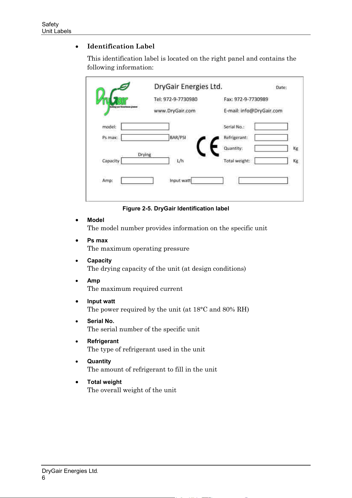
• Identification Label
This identification label is located on the right panel and contains the
following information:
Figure 2-5. DryGair Identification label
• Model
The model number provides information on the specific unit
•
Ps max
The maximum operating pressure
• Capacity
The drying capacity of the unit (at design conditions)
• Amp
The maximum required current
• Input watt
The power required by the unit (at 18°C and 80% RH)
• Serial No.
The serial number of the specific unit
• Refrigerant
The type of refrigerant used in the unit
• Quantity
The amount of refrigerant to fill in the unit
• Total weight
The overall weight of the unit
DryGair Energies Ltd.
6
Page 13
DryGair Dehumidification Unit
Unit Overview
3. UNIT OVERVIEW
The DryGair dehumidifying unit is designed and manufactured by DryGair
Energies Ltd. The unit is designed for the dehumidification of greenhouses,
and can also be used in any other closed structure.
The unit reduces the humidity in the greenhouse according to a defined set-
point by pulling the wet cold air from the bottom of the greenhouse,
extracting the water, heating the air, and blowing the drier and warmer air
back into the greenhouse through an air distribution module.
The unit can also be configured to heat or cool the dried air.
The water condensed during the dehumidification process is removed from
the greenhouse through water drainage, and can be reused for other purposes
such as a hydroponic system.
3.1 Standard Features
The standard unit includes the following features:
• Humidification Set-Point – ensures the humidity in the greenhouse is
kept at this set-point.
• Temperature Control –stops the unit when the temperature drops to
10°C, and goes through a defrost cycle when reaching 6°C.
3.2 Available Models
The DryGair dehumidifying unit includes the following main models:
• Standard (Large)
• Small
• Warm Climate
Each of the above models can be configured as follows:
• Split configuration.
• With Heating & Cooling
• 50 Hz or 60 Hz.
Ver. 11/17
7
Page 14
Unit Overview
Note
The configuration cannot be changed at the customer’s site.
Options
3.3 Options
The DryGair unit can include one or more of the following options:
• Side Canopy – a 1-direction air vent.
• Combined Heating and Cooling – a water-based coil for heating or
cooling the air exiting the unit.
• Noise Reduction – an option for adding noise insulation to receive a
quieter unit.
• Protecting Wire-Net – a net for protecting the coil outer fins.
• Environmental Resistance – the unit parts are made of materials that
improve their resistance to chemicals and soil disinfectants.
• Wheels – set of wheels for unit mobility.
For more details on the available options, types and configurations, see
Appendix B and Appendix D.
DryGair Energies Ltd.
8
Page 15
DryGair Dehumidification Unit
Note
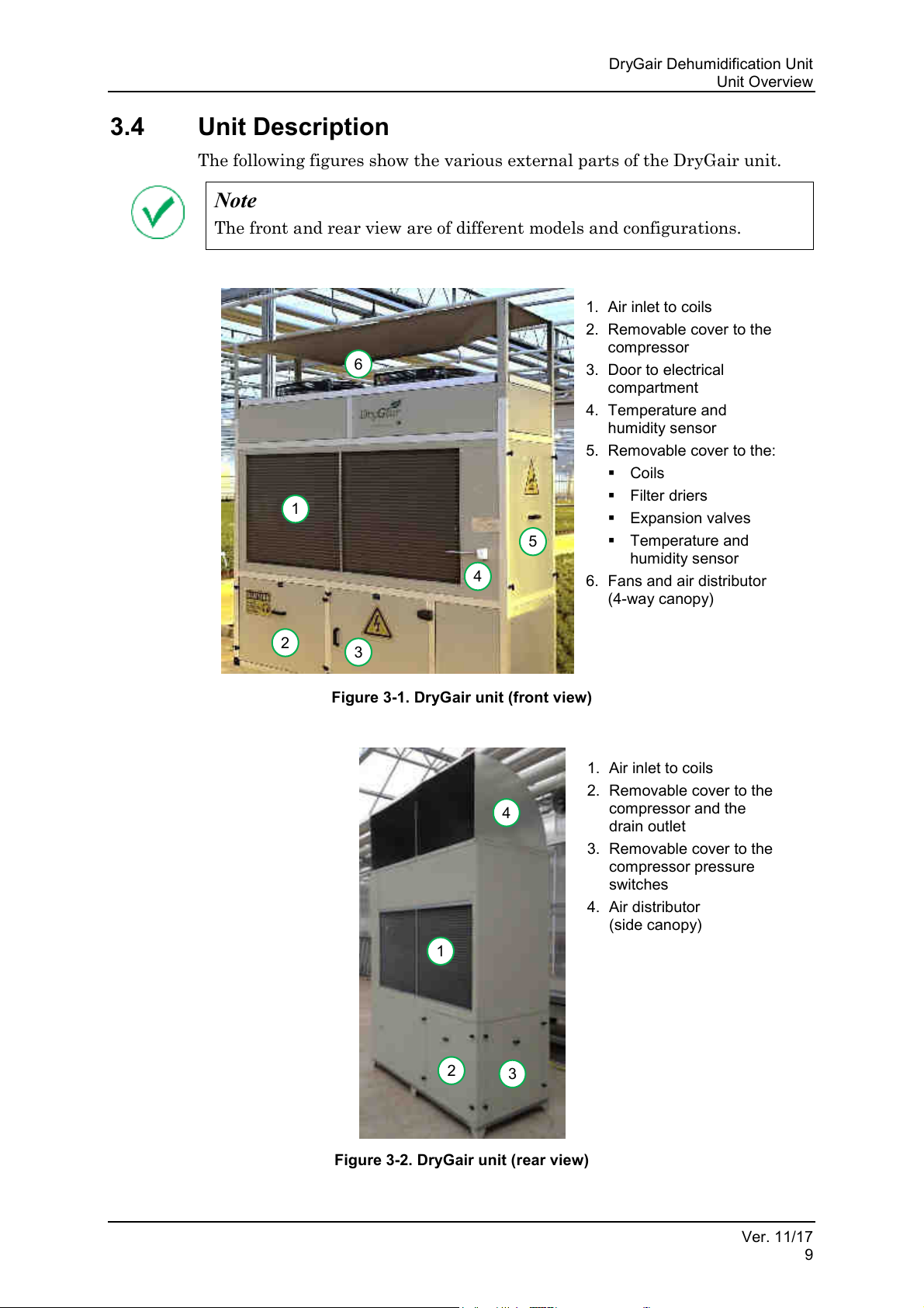
The front and rear view are of different models and configurations.
1.
2.
3.
4.
5. Removable cover to the:
6.
(4-way canopy)
1
2
3
5
4
6
1.
2. Removable cover to the
3. Removable cover to the
4.
(side canopy)
2
3
4
1
Unit Overview
3.4 Unit Description
The following figures show the various external parts of the DryGair unit.
Air inlet to coils
Removable cover to the
compressor
Door to electrical
compartment
Temperature and
humidity sensor
▪ Coils
▪ Filter driers
▪ Expansion valves
▪ Temperature and
humidity sensor
Fans and air distributor
Figure 3-1. DryGair unit (front view)
Air inlet to coils
compressor and the
drain outlet
compressor pressure
switches
Air distributor
Figure 3-2. DryGair unit (rear view)
Ver. 11/17
9
Page 16
Installation
Note
The site should be prepared before unpacking and powering-on.
Warning
The unit condensation water is not for drinking!
Site Preparation
4. INSTALLATION
The installation chapter includes the site preparation, uncrating the unit and
installation instructions of the DryGair dehumidification unit.
4.1 Site Preparation
Prepare the installation site before receiving the DryGair unit.
4.1.1 Site Requirements
• The DryGair unit should be installed inside a greenhouse and located in
an accessible location for operation and maintenance. The unit should
preferably be located in the center of the greenhouse, blowing air towards
the plants.
• If the unit is placed next to the greenhouse wall, ensure it is distanced at
least 50 centimeters from the wall, and blowing air towards the plants.
• The unit should be placed on a concrete leveled surface, or on tiles built
according the unit dimensions and weight (see section 4.1.2 and Appendix
B).
• The unit in its final position should be positioned at a height the air
distributor (canopy) is just below the thermal screen (if exists) and the
unit's blowers are above the plants. The air should be distributed to the
center of the greenhouse.
• If the plants growing method is high-gutter, the unit should be elevated
on stable designed tables to a height that enables efficient and safe
operation of the unit.
• The transit lanes inside the greenhouse where the unit is to be installed
must be kept clear, and the floor must be clean and free from any
obstacles that might cause the forklift, truck or crane to “jump”.
• An electrical shut off switch (3×32 Amp), unless stated otherwise (e.g.,
small units), should be prepared and located in a protected location near
the unit.
• Drainage should be prepared for removal of the water that is condensed
by the unit. The unit is supplied with a metal 1½" BSP threaded bushing.
The prepared drainage should include a siphon.
• The site should be equipped with suitable climbing equipment to enable
safe and comfortable access to the unit top.
DryGair Energies Ltd.
10
Page 17
DryGair Dehumidification Unit
Specification
Value
Dimensions
Depth
930 mm
Width
2,320 mm
Weight
~775 kg
Height*
2,220 mm + ~500 mm
Air distribution module
Coverage Area **
Up to 4,000 m2
Temperature Operation Range
10°C – 25°C
Water Condensation
(@18°C and 80% RH)
45 L/h
Electricity Requirements
3-phase, 32 Amp, 400 V, 50 Hz
Electricity Consumption
(@18°C and 80% RH)
10 kWh
Air Flow
~22,000 m³/h
Refrigerant Type
R507
Specification
Value
Dimensions
Depth
920 mm
Width
2,300 mm
Weight
~550 kg
Height*
1,900 m + ~500 mm
Air distribution module
Coverage Area **
Up to 2,000 m2
Temperature Operation Range
10°C – 25°C
Water Condensation
(@18°C and 80% RH)
24 L/h
Electricity Requirements
3-phase, 24 Amp, 400 V, 50 Hz
Electricity Consumption
(@18°C and 80% RH)
6 kWh
Air Flow
~12,000 m³/h
Refrigerant Type
R507
Installation
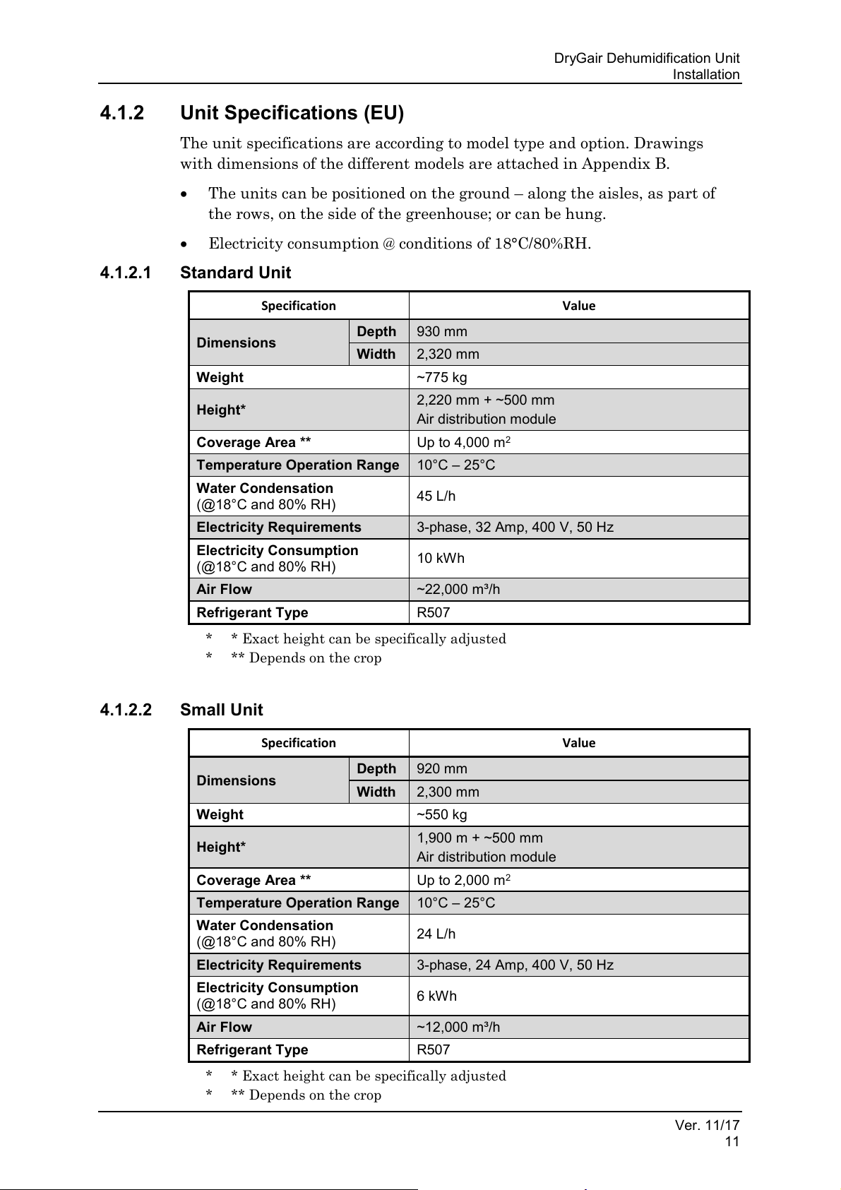
4.1.2 Unit Specifications (EU)
The unit specifications are according to model type and option. Drawings
with dimensions of the different models are attached in Appendix B.
• The units can be positioned on the ground – along the aisles, as part of
the rows, on the side of the greenhouse; or can be hung.
• Electricity consumption @ conditions of 18°C/80%RH.
4.1.2.1 Standard Unit
* * Exact height can be specifically adjusted
* ** Depends on the crop
4.1.2.2 Small Unit
Ver. 11/17
11
* * Exact height can be specifically adjusted
* ** Depends on the crop
Page 18
Installation
Specification
Upper part
Lower Part
Dimensions
Depth
930 mm
820 mm ***
Width
2,320 mm
1,900 mm
Weight
~550 kg
~330 kg
Height*
1,600 mm + ~500 mm
Air distribution module (adjustable)
900 mm
Coverage Area **
Up to 4,000 m2
Temperature Operation
Range
10°C – 25°C
Water Condensation
(@18°C and 80% RH)
45 L/h
Electricity Requirements
3-phase, 32 Amp, 400 V, 50 Hz
Electricity Consumption
(@18°C and 80% RH)
10 kWh
Air Flow
~22,000 m³/h
Refrigerant Type
R507
Note
Max. distance between unit upper and lower units:
4 meters.
Specification
Upper part
Lower Part
Dimensions
Depth
920 mm
820 mm ***
Width
2,300 mm
1,655 mm
Weight
~330 kg
~325 kg
Height*
1,160 mm + ~500 m
Air distribution module (adjustable)
900 mm
Coverage Area **
Up to 2,000 m2
Temperature Operation Range
10°C – 25°C
Water Condensation
(@18°C and 80% RH)
24 L/h
Electricity Requirements
3-phase, 24 Amp, 400 V, 50 Hz
Electricity Consumption
(@18°C and 80% RH)
6 kWh
Air Flow
~12,000 m³/h
Refrigerant Type
R507
Note
Max. distance between unit upper and lower units:
4 meters.
Site Preparation
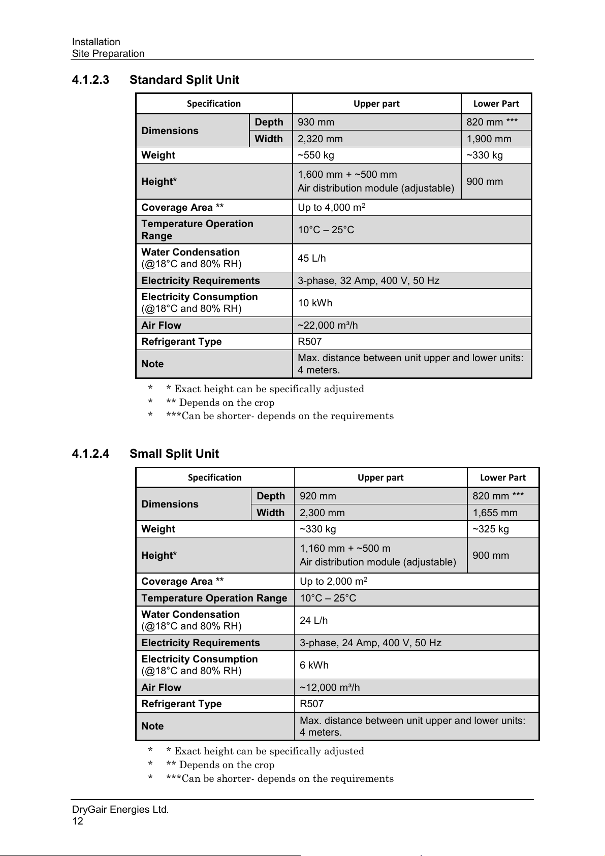
4.1.2.3 Standard Split Unit
* * Exact height can be specifically adjusted
* ** Depends on the crop
* ***Can be shorter- depends on the requirements
4.1.2.4 Small Split Unit
* * Exact height can be specifically adjusted
* ** Depends on the crop
* ***Can be shorter- depends on the requirements
DryGair Energies Ltd.
12
Page 19
DryGair Dehumidification Unit
Specification
Value
Dimensions
Depth
930 mm
Width
2,320 mm
Weight
~825 kg
Height*
2,360 mm + ~500 mm
Air distribution module
Hot water pipe connection
300 mm
Coverage Area **
Up to 4,000 m2
Temperature Operation Range
10°C – 25°C
Water Condensation
(@18°C and 80% RH)
45 L/h
Electricity Requirements
3-phase, 32 Amp, 400 V, 50 Hz
Electricity Consumption
(@18°C and 80% RH)
10 kWh
Air Flow
~22,000 m³/h
Refrigerant Type
R507
Specification
Value
Dimensions
Depth
920 mm
Width
2,300 mm
Weight
~600 kg
Height*
2,030 mm + ~500 mm
Air distribution module
Hot water pipe connection
300 mm
Coverage Area **
Up to 2,000 m2
Temperature Operation Range
10°C – 25°C
Water Condensation
(@18°C and 80% RH)
24 L/h
Electricity Requirements
3-phase, 24 Amp, 400 V, 50 Hz
Electricity Consumption
(@18°C and 80% RH)
6 kWh
Air Flow
~12,000 m³/h
Refrigerant Type
R507
Installation
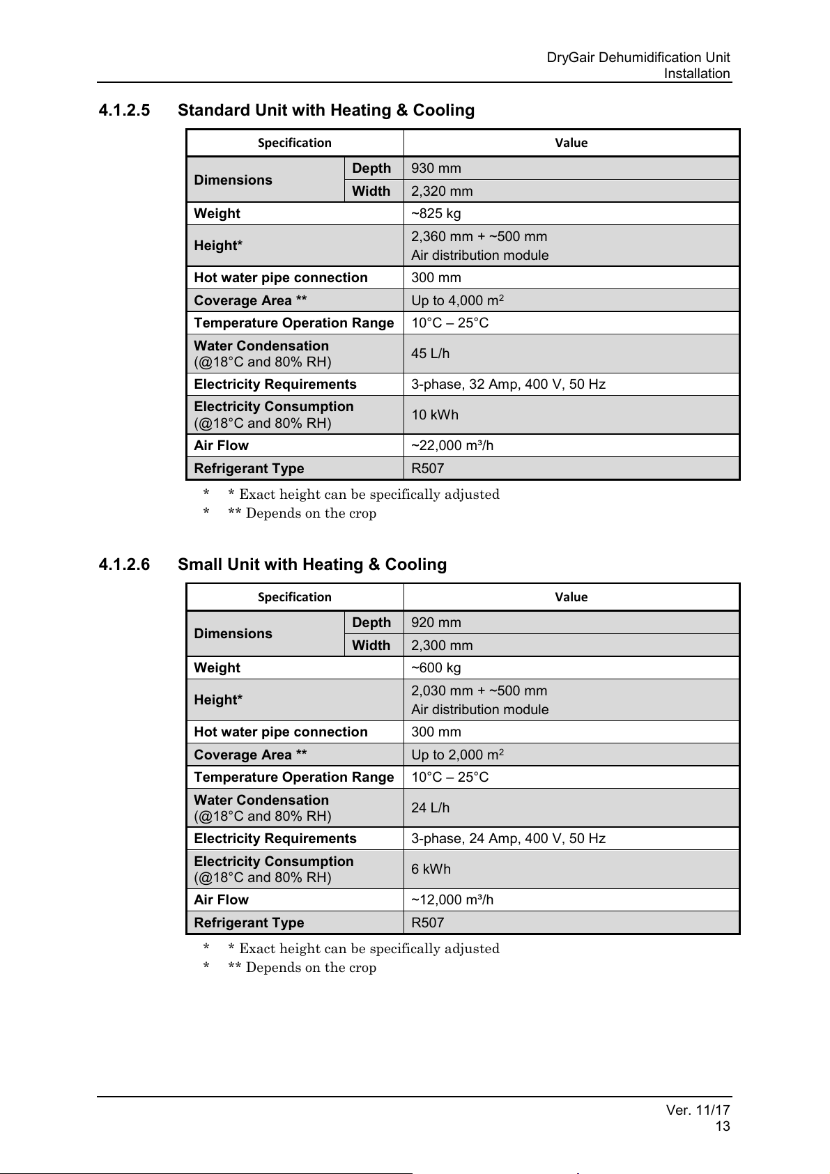
4.1.2.5 Standard Unit with Heating & Cooling
* * Exact height can be specifically adjusted
* ** Depends on the crop
4.1.2.6 Small Unit with Heating & Cooling
Ver. 11/17
13
* * Exact height can be specifically adjusted
* ** Depends on the crop
Page 20
Installation
Specification
Upper part
Lower Part
Dimensions
Depth
930 mm
820 mm
Width
2,320 mm
1,900 mm
***
Weight
~600 kg
~330 kg
Height*
1,740 mm + ~500 mm
Air distribution module (adjustable)
900 mm
Hot water pipe connection
300 mm
Coverage Area **
Up to 4,000 m2
Temperature Operation
Range
10°C – 25°C
Water Condensation
(@18°C and 80% RH)
45 L/h
Electricity Requirements
3-phase, 32 Amp, 400 V, 50 Hz
Electricity Consumption
(@18°C and 80% RH)
10 kWh
Air Flow
~22,000 m³/h
Refrigerant Type
R507
Note
Max. distance between unit upper and lower units:
4 meters.
Specification
Upper part
Lower Part
Dimensions
Depth
920 mm
820 mm
Width
2,300 mm
1,655 mm ***
Weight
~550 kg
~325 kg
Height*
1.30 m + ~0.5 m
Air distribution module (adjustable)
900 mm
Hot water pipe connection
300 mm
Coverage Area **
Up to 2,000 m2
Temperature Operation Range
10°C – 25°C
Water Condensation
(@18°C and 80% RH)
24 L/h
Electricity Requirements
3-phase, 24 Amp, 400 V, 50 Hz
Electricity Consumption
(@18°C and 80% RH)
6 kWh
Air Flow
~12,000 m³/h
Refrigerant Type
R507
Note
Max. distance between the unit upper and lower
units: 4 meters.
Site Preparation
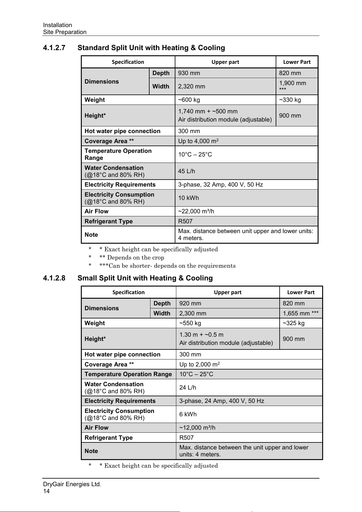
4.1.2.7 Standard Split Unit with Heating & Cooling
* * Exact height can be specifically adjusted
* ** Depends on the crop
* ***Can be shorter- depends on the requirements
4.1.2.8 Small Split Unit with Heating & Cooling
* * Exact height can be specifically adjusted
DryGair Energies Ltd.
14
Page 21
DryGair Dehumidification Unit
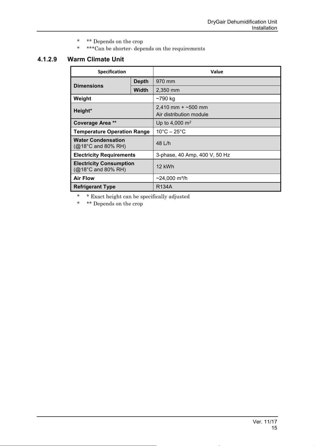
Specification
Value
Dimensions
Depth
970 mm
Width
2,350 mm
Weight
~790 kg
Height*
2,410 mm + ~500 mm
Air distribution module
Coverage Area **
Up to 4,000 m2
Temperature Operation Range
10°C – 25°C
Water Condensation
(@18°C and 80% RH)
48 L/h
Electricity Requirements
3-phase, 40 Amp, 400 V, 50 Hz
Electricity Consumption
(@18°C and 80% RH)
12 kWh
Air Flow
~24,000 m³/h
Refrigerant Type
R134A
Installation
* ** Depends on the crop
* ***Can be shorter- depends on the requirements
4.1.2.9 Warm Climate Unit
* * Exact height can be specifically adjusted
* ** Depends on the crop
Ver. 11/17
15
Page 22
Installation
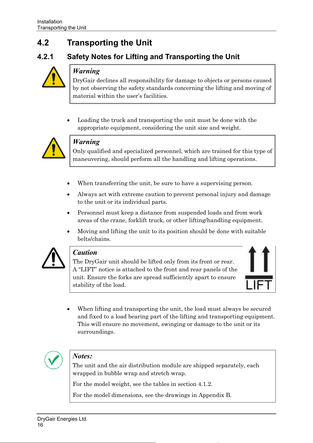
Warning
DryGair declines all responsibility for damage to objects or persons caused
by not observing the safety standards concerning the lifting and moving of
material within the user’s facilities.
Warning
Only qualified and specialized personnel, which are trained for this type of
maneuvering, should perform all the handling and lifting operations.
Caution
The DryGair unit should be lifted only from its front or rear.
A “LIFT” notice is attached to the front and rear panels of the
unit. Ensure the forks are spread sufficiently apart to ensure
stability of the load.
Notes:
The unit and the air distribution module are shipped separately, each
wrapped in bubble wrap and stretch wrap.
For the model weight, see the tables in section 4.1.2.
For the model dimensions, see the drawings in Appendix B.
Transporting the Unit
4.2 Transporting the Unit
4.2.1 Safety Notes for Lifting and Transporting the Unit
• Loading the truck and transporting the unit must be done with the
appropriate equipment, considering the unit size and weight.
• When transferring the unit, be sure to have a supervising person.
• Always act with extreme caution to prevent personal injury and damage
to the unit or its individual parts.
• Personnel must keep a distance from suspended loads and from work
areas of the crane, forklift truck, or other lifting/handling equipment.
• Moving and lifting the unit to its position should be done with suitable
belts/chains.
• When lifting and transporting the unit, the load must always be secured
and fixed to a load bearing part of the lifting and transporting equipment.
This will ensure no movement, swinging or damage to the unit or its
surroundings.
DryGair Energies Ltd.
16
Page 23
DryGair Dehumidification Unit
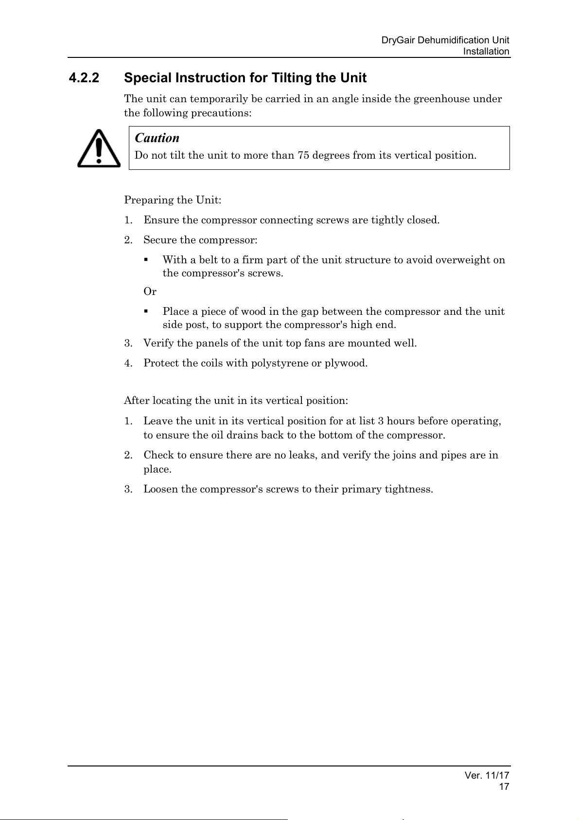
Caution
Do not tilt the unit to more than 75 degrees from its vertical position.
Installation
4.2.2 Special Instruction for Tilting the Unit
The unit can temporarily be carried in an angle inside the greenhouse under
the following precautions:
Preparing the Unit:
1. Ensure the compressor connecting screws are tightly closed.
2. Secure the compressor:
▪ With a belt to a firm part of the unit structure to avoid overweight on
the compressor's screws.
Or
▪ Place a piece of wood in the gap between the compressor and the unit
side post, to support the compressor's high end.
3. Verify the panels of the unit top fans are mounted well.
4. Protect the coils with polystyrene or plywood.
After locating the unit in its vertical position:
1. Leave the unit in its vertical position for at list 3 hours before operating,
to ensure the oil drains back to the bottom of the compressor.
2. Check to ensure there are no leaks, and verify the joins and pipes are in
place.
3. Loosen the compressor's screws to their primary tightness.
Ver. 11/17
17
Page 24
Installation
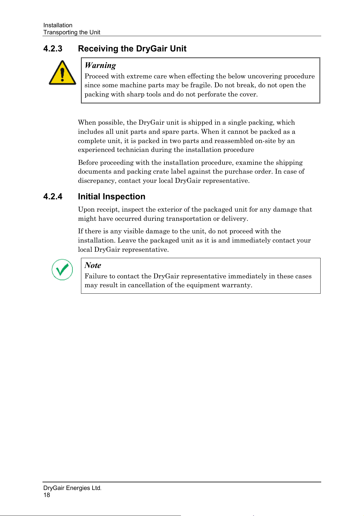
Warning
Proceed with extreme care when effecting the below uncovering procedure
since some machine parts may be fragile. Do not break, do not open the
packing with sharp tools and do not perforate the cover.
Note
Failure to contact the DryGair representative immediately in these cases
may result in cancellation of the equipment warranty.
Transporting the Unit
4.2.3 Receiving the DryGair Unit
When possible, the DryGair unit is shipped in a single packing, which
includes all unit parts and spare parts. When it cannot be packed as a
complete unit, it is packed in two parts and reassembled on-site by an
experienced technician during the installation procedure
Before proceeding with the installation procedure, examine the shipping
documents and packing crate label against the purchase order. In case of
discrepancy, contact your local DryGair representative.
4.2.4 Initial Inspection
Upon receipt, inspect the exterior of the packaged unit for any damage that
might have occurred during transportation or delivery.
If there is any visible damage to the unit, do not proceed with the
installation. Leave the packaged unit as it is and immediately contact your
local DryGair representative.
DryGair Energies Ltd.
18
Page 25
DryGair Dehumidification Unit
Caution
Do not open the packing with sharp tools.
Installation
4.3 Unpacking the Unit
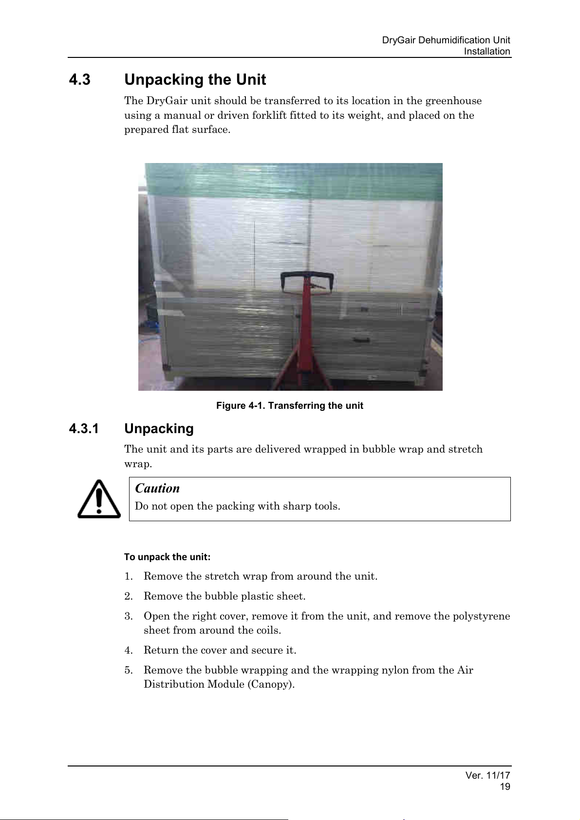
The DryGair unit should be transferred to its location in the greenhouse
using a manual or driven forklift fitted to its weight, and placed on the
prepared flat surface.
4.3.1 Unpacking
The unit and its parts are delivered wrapped in bubble wrap and stretch
wrap.
To unpack the unit:
1. Remove the stretch wrap from around the unit.
2. Remove the bubble plastic sheet.
3. Open the right cover, remove it from the unit, and remove the polystyrene
sheet from around the coils.
4. Return the cover and secure it.
5. Remove the bubble wrapping and the wrapping nylon from the Air
Distribution Module (Canopy).
Figure 4-1. Transferring the unit
Ver. 11/17
19
Page 26
Installation
#
Part Description
DryGair Part Number
Qty
Main Unit
1
Air Distribution Module (Canopy)
1
Accessories:
N/A
Rubber pads *
(shock absorbing and leveling)
6
Screws and Washers*
N/A
Note
Verify all parts and ordered items were received and that they are not
damaged. Inform the carrier and your local DryGair representative
immediately if any part is missing or damaged.
Unpacking the Unit
4.3.2 Parts List Received
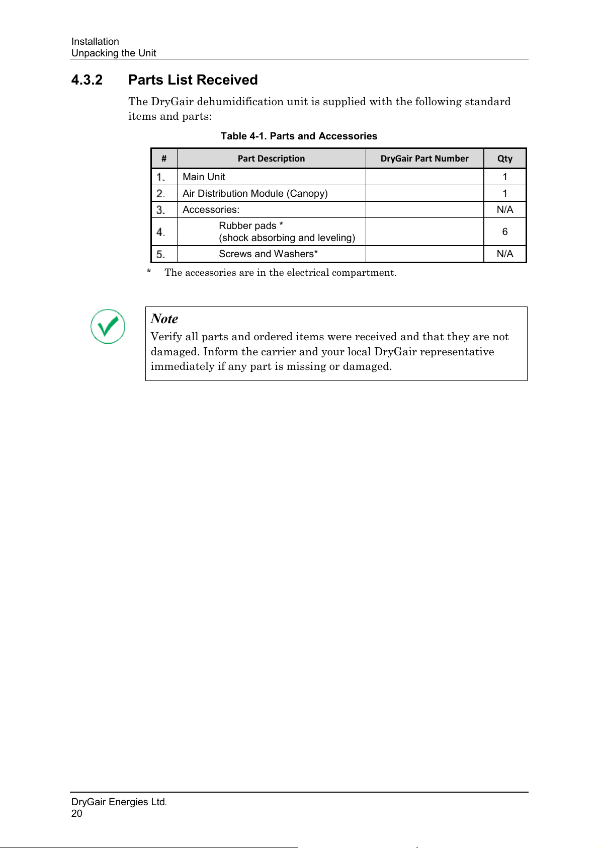
The DryGair dehumidification unit is supplied with the following standard
items and parts:
Table 4-1. Parts and Accessories
* The accessories are in the electrical compartment.
DryGair Energies Ltd.
20
Page 27
DryGair Dehumidification Unit
Note
For split units see specific details in Appendix D section D.1.
Notes
• The 4-direction Air Distribution Module (canopy) is not symmetric.
When looking at the unit from the front, the canopy should be
installed so that its moderate slope is connected to the right side of the
unit, (see Appendix B section C.1).
• The 1-direction Air Distribution Module (canopy) should be connected
with its opening facing the center of the greenhouse, blowing the air
towards the plants, (see Appendix B section C.2).
Warning
Observe safety regulations when using a stepladder to connect the Air
Distributor Module.
• Inspect the stepladder to makes sure it is in good condition.
• Choose a safe spot to anchor the stepladder.
• Work with a partner. One person should hold the stepladder steady.
Installation
4.4 Positioning the Unit
To position the unit:
1. Place the supplied rubber pads at the locations of the unit legs (6 legs).
These rubber pads act as shock absorbers and for leveling the unit.
2. Lift the unit, and position it on the rubber pads.
3. Ensure the Air Distribution Module is just below the thermal screen (if
exists) and the unit's fans are above the plants.
4. Level the unit and verify it is stable.
5. Connect the Air Distribution Module (Canopy).
The Air Distribution Module type is ordered with the unit, as
recommended by DryGair. The optional types are shown in Appendix B.
To connect the Air Distribution Module (Canopy):
1. Lift the module to the top of the unit.
2. Ensure the air distribution is directed towards the center of the
greenhouse.
3. Connect it to the unit frame, using the supplied screws.
Ver. 11/17
21
4. Ensure the module is tightly secured and that its height is just below the
thermal screen (if exists).
Page 28
Installation
Note
If the unit is to be connected to a climate control system, have your IT
expert on-site for the first power up.
Note
To prevent water accumulation, the water drain pipe should be connected
by a plumber to a drainage line leading outside the greenhouse or to any
other place the water should be collected (as a container).
1
2
1.
2.
(not supplied)
Connecting the Utilities
After the unit is installed, call your electrician and the local DryGair
technician to complete unit installation and to perform the first unit
activation.
4.5 Connecting the Utilities
The following procedure describes how to connect the external utilities to the
DryGair dehumidification unit.
4.5.1 Connecting the Water Drain Pipe
During unit operation, water is condensed and needs to be removed from the
unit. In some environments, depending on the air temperature and humidity,
this may be a large quantity of water.
Remove the rear cover from the unit.
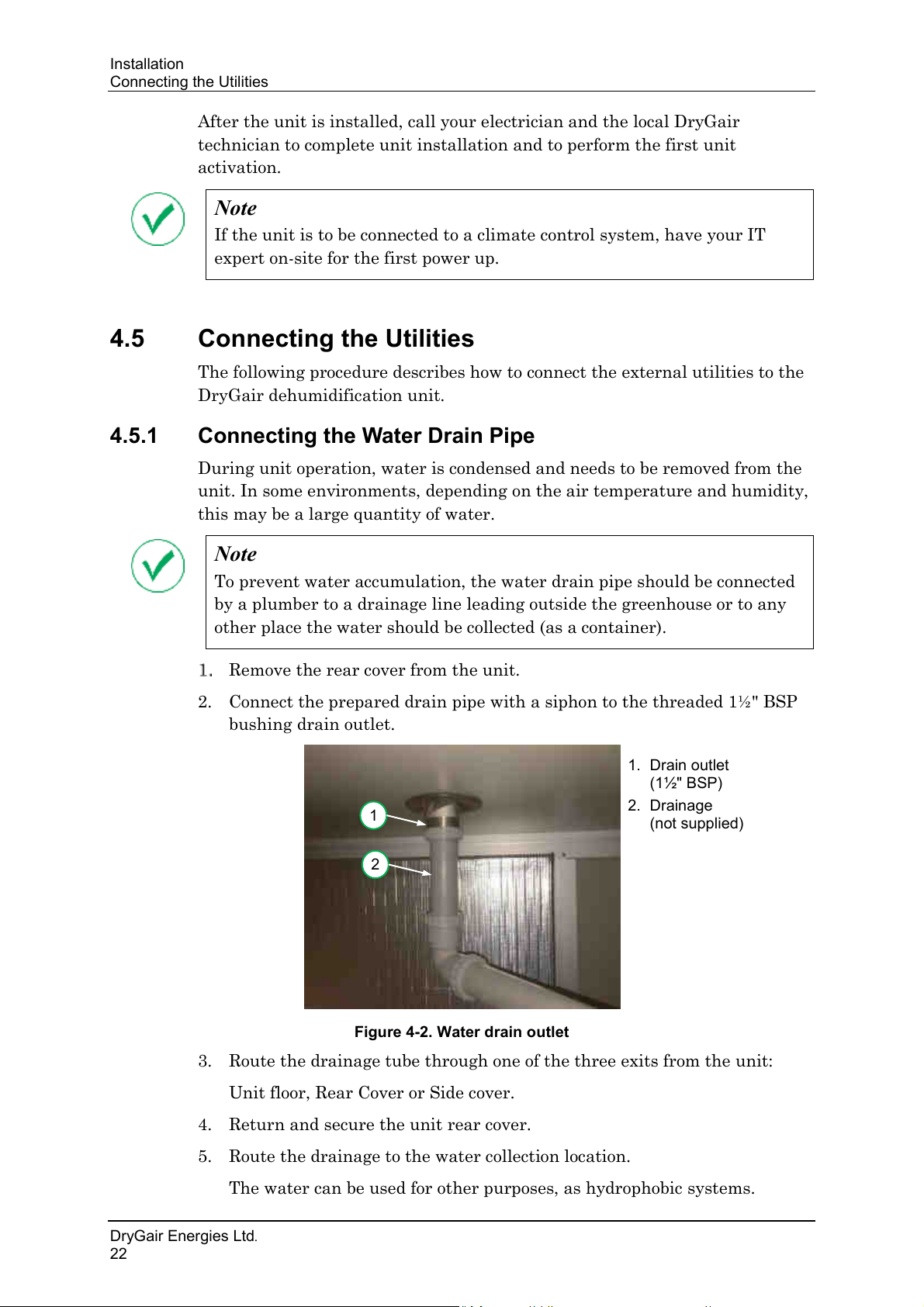
2. Connect the prepared drain pipe with a siphon to the threaded 1½" BSP
bushing drain outlet.
Drain outlet
(1½" BSP)
Drainage
Figure 4-2. Water drain outlet
3. Route the drainage tube through one of the three exits from the unit:
Unit floor, Rear Cover or Side cover.
4. Return and secure the unit rear cover.
5. Route the drainage to the water collection location.
The water can be used for other purposes, as hydrophobic systems.
DryGair Energies Ltd.
22
Page 29
DryGair Dehumidification Unit
Warning
Only a certified electrician is authorized to connect the unit to the grid.
Warning
Verify the circuit breaker is turned OFF.
L1
L2
L3
N
Grnd
Installation
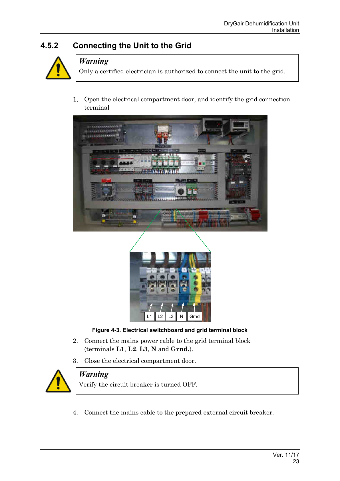
4.5.2 Connecting the Unit to the Grid
Open the electrical compartment door, and identify the grid connection
terminal
Figure 4-3. Electrical switchboard and grid terminal block
2. Connect the mains power cable to the grid terminal block
(terminals L1, L2, L3, N and Grnd.).
3. Close the electrical compartment door.
4. Connect the mains cable to the prepared external circuit breaker.
Ver. 11/17
23
Page 30
Unit Parts and Components
1. Temperature and
humidity sensor
1
1.
humidity sensor unit
1
Temperature and Humidity Sensor
5. UNIT PARTS AND COMPONENTS
The following figures show the various parts and components of the DryGair
dehumidification unit.
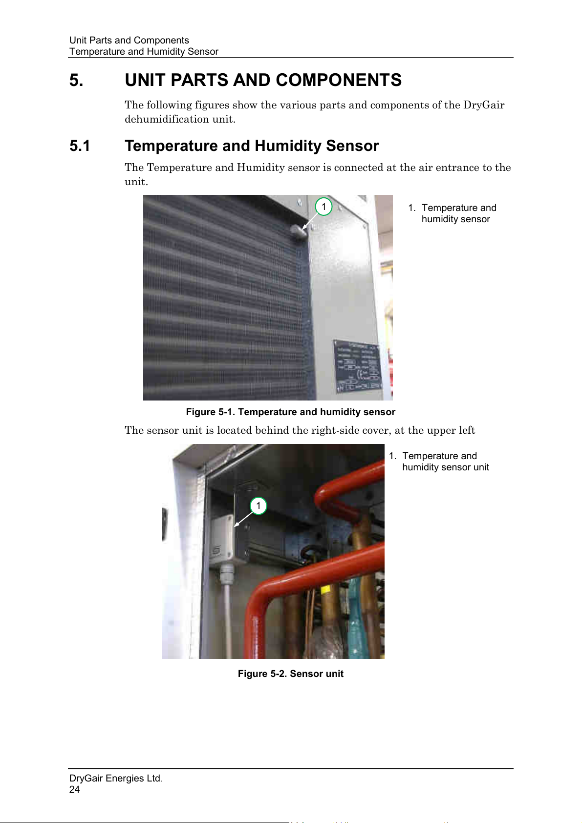
5.1 Temperature and Humidity Sensor
The Temperature and Humidity sensor is connected at the air entrance to the
unit.
Figure 5-1. Temperature and humidity sensor
The sensor unit is located behind the right-side cover, at the upper left
Temperature and
Figure 5-2. Sensor unit
DryGair Energies Ltd.
24
Page 31
DryGair Dehumidification Unit
1. Defrost temperature
sensor cable
1
Unit Parts and Components
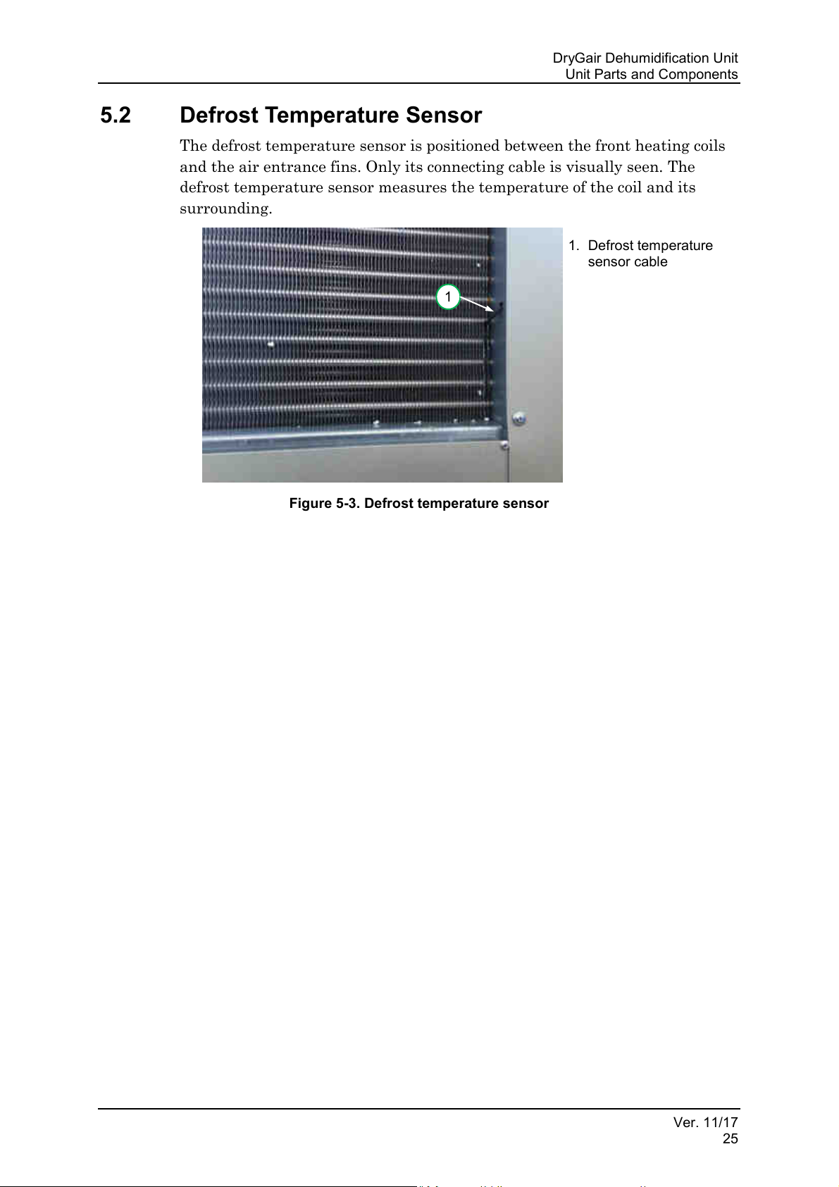
5.2 Defrost Temperature Sensor
The defrost temperature sensor is positioned between the front heating coils
and the air entrance fins. Only its connecting cable is visually seen. The
defrost temperature sensor measures the temperature of the coil and its
surrounding.
Figure 5-3. Defrost temperature sensor
Ver. 11/17
25
Page 32
Unit Parts and Components
Warning
Danger: There is High voltage in the electrical compartment! Opening
the electric compartment should only be done by authorized personnel or a
certified electrician.
8
1
3
7
6
5
4
2
Electrical Compartment
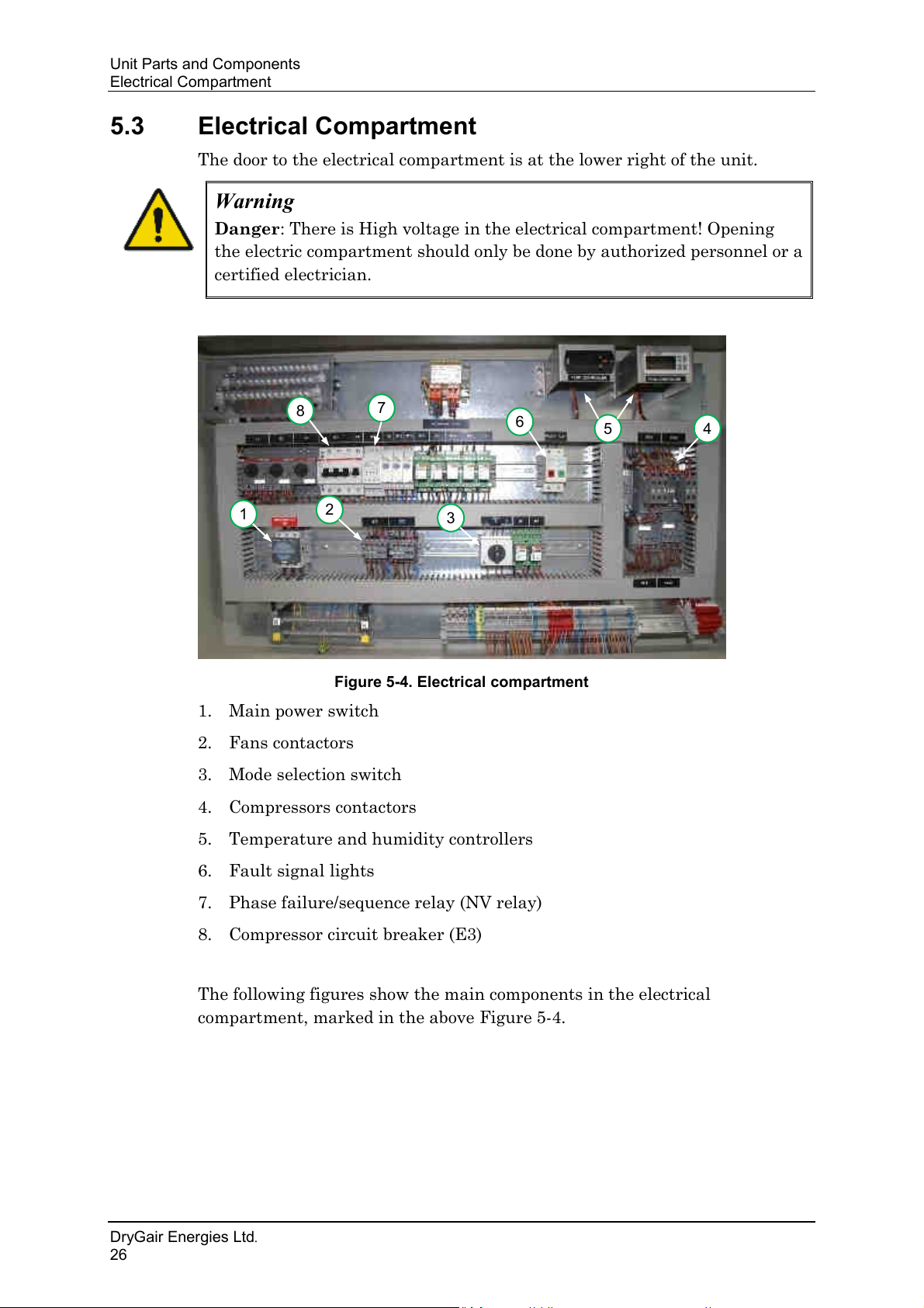
5.3 Electrical Compartment
The door to the electrical compartment is at the lower right of the unit.
Figure 5-4. Electrical compartment
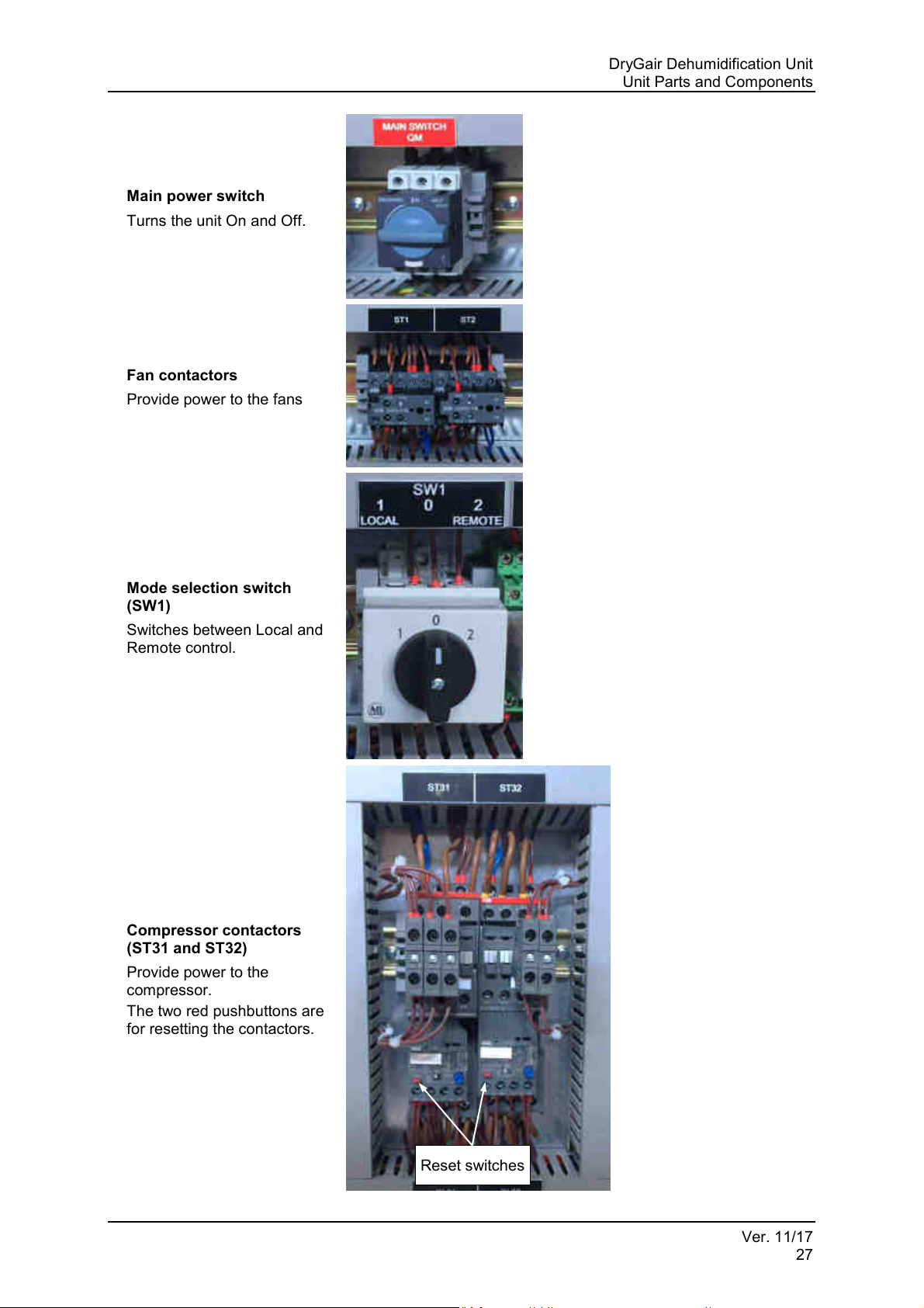
1. Main power switch
2. Fans contactors
3. Mode selection switch
4. Compressors contactors
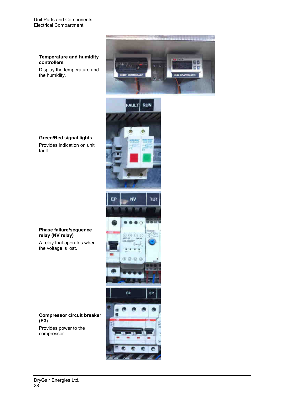
5. Temperature and humidity controllers
6. Fault signal lights
7. Phase failure/sequence relay (NV relay)
8. Compressor circuit breaker (E3)
The following figures show the main components in the electrical
compartment, marked in the above Figure 5-4.
DryGair Energies Ltd.
26
Page 33
DryGair Dehumidification Unit
Main power switch
Turns the unit On and Off.
Fan contactors
Provide power to the fans
Mode selection switch
(SW1)
Switches between Local and
Remote control.
Compressor contactors
(ST31 and ST32)
Provide power to the
compressor.
The two red pushbuttons are
for resetting the contactors.
Reset switches
Unit Parts and Components
Ver. 11/17
27
Page 34
Unit Parts and Components
Temperature and humidity
controllers
Display the temperature and
the humidity.
Green/Red signal lights
Provides indication on unit
fault.
Phase failure/sequence
relay (NV relay)
A relay that operates when
the voltage is lost.
Compressor circuit breaker
(E3)
Provides power to the
compressor.
Electrical Compartment
DryGair Energies Ltd.
28
Page 35
DryGair Dehumidification Unit
Caution
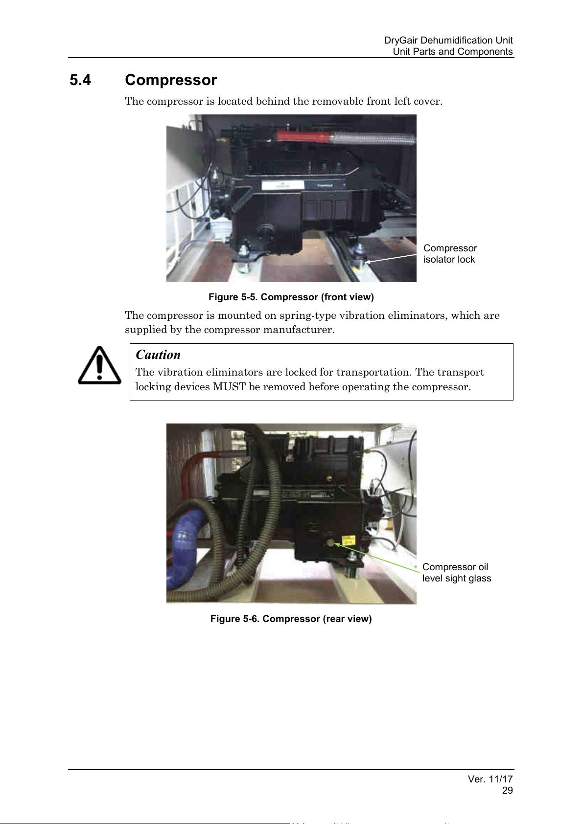
The vibration eliminators are locked for transportation. The transport
locking devices MUST be removed before operating the compressor.
Compressor
isolator lock
Compressor oil
level sight glass
Unit Parts and Components
5.4 Compressor
The compressor is located behind the removable front left cover.
Figure 5-5. Compressor (front view)
The compressor is mounted on spring-type vibration eliminators, which are
supplied by the compressor manufacturer.
Figure 5-6. Compressor (rear view)
Ver. 11/17
29
Page 36
Unit Parts and Components
Caution
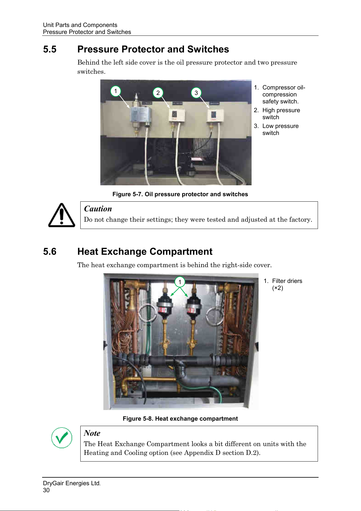
Do not change their settings; they were tested and adjusted at the factory.
Note
The Heat Exchange Compartment looks a bit different on units with the
Heating and Cooling option (see Appendix D section D.2).
1.
2.
3.
switch
1
2
3
1.
(×2)
1
Pressure Protector and Switches
5.5 Pressure Protector and Switches
Behind the left side cover is the oil pressure protector and two pressure
switches.
Figure 5-7. Oil pressure protector and switches
Compressor oil-
compression
safety switch.
High pressure
switch
Low pressure
5.6 Heat Exchange Compartment
The heat exchange compartment is behind the right-side cover.
Figure 5-8. Heat exchange compartment
Filter driers
DryGair Energies Ltd.
30
Page 37
DryGair Dehumidification Unit
1.
valves (×2)
1
1.
(×2)
1
Unit Parts and Components
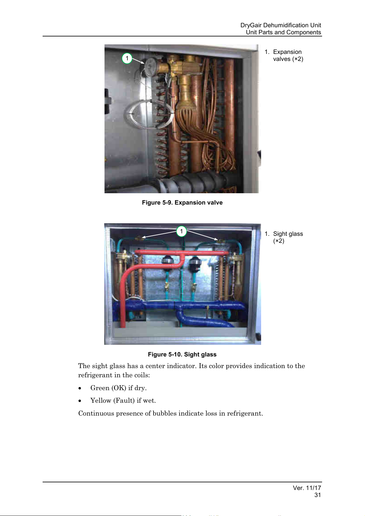
Expansion
Figure 5-9. Expansion valve
Sight glass
Figure 5-10. Sight glass
The sight glass has a center indicator. Its color provides indication to the
refrigerant in the coils:
• Green (OK) if dry.
• Yellow (Fault) if wet.
Continuous presence of bubbles indicate loss in refrigerant.
Ver. 11/17
31
Page 38
Unit Parts and Components
1
1.
(×2)
Blowing Fans
5.7 Blowing Fans
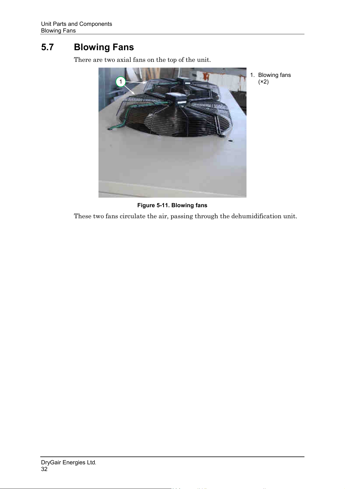
There are two axial fans on the top of the unit.
Blowing fans
Figure 5-11. Blowing fans
These two fans circulate the air, passing through the dehumidification unit.
DryGair Energies Ltd.
32
Page 39
DryGair Dehumidification Unit
Note
Operating the unit should be done only after receiving training from the
representative of DryGair.
Warning
Opening the electric compartment should only be done by authorized
personnel or a certified electrician.
Caution
According to the kind of work being performed on the unit, wear personal
protection devices such as: helmet, eye protection glasses, protection
shoes, ears noise protection, etc. All according to state law and regulation
and/or according to management instructions.
Caution
Prevent unauthorized personnel from being near the unit without a
qualified person.
Unit Operation
6. UNIT OPERATION
The operation chapter explains how to use the DryGair unit.
6.1 Operation Precautions
Before operating the unit, verify you are familiar with the following:
• The locations of the main shut off switches in case of emergency.
• The hazards areas and moving parts of the unit.
• What is behind each cover, and risks related to that area.
• The electrical compartment: high voltage and low voltage areas.
• Operating the unit and stopping the unit.
• The climate control system (if applicable).
Ver. 11/17
33
Page 40
Unit Operation
Caution
Initial operation should be done by a professional person that is approved
by DryGair Energies Ltd.
Note
For split units see and follow the instructions provided in Appendix D
section D.1.
Caution
Before powering the unit on, visually check that all doors and covers of the
unit are closed, and that the unit inside and surroundings are clean from
any parts, tools, etc.
Preparing the Unit for Operation
6.2 Preparing the Unit for Operation
Preparing and setting the unit includes the following actions:
• Preliminary Checks (section 6.2.1)
• Powering On (section 6.2.2)
• Setting the Humidity Percentage (section 6.2.3)
• Setting the Temperature (section 6.2.4)
• Selecting the Operation Mode (section 6.2.5)
6.2.1 Preliminary Checks
1. Make sure the main switch is OFF and unauthorized personnel are not
near the machine.
2. Confirm the DryGair unit is stable and leveled.
3. Confirm the air distribution module (canopy) is installed and secured.
4. Confirm the drainage pipe installed and routed away from the unit.
5. Perform a visual check that everything is in place.
DryGair Energies Ltd.
34
Page 41
DryGair Dehumidification Unit
Warning
High voltage is present at points throughout the unit. Contact can result
in injury or death. Before opening the unit electrical compartment, ensure
you are familiar with the location of the external circuit breaker to the
unit.
Unit Operation
6.2.2 Powering On
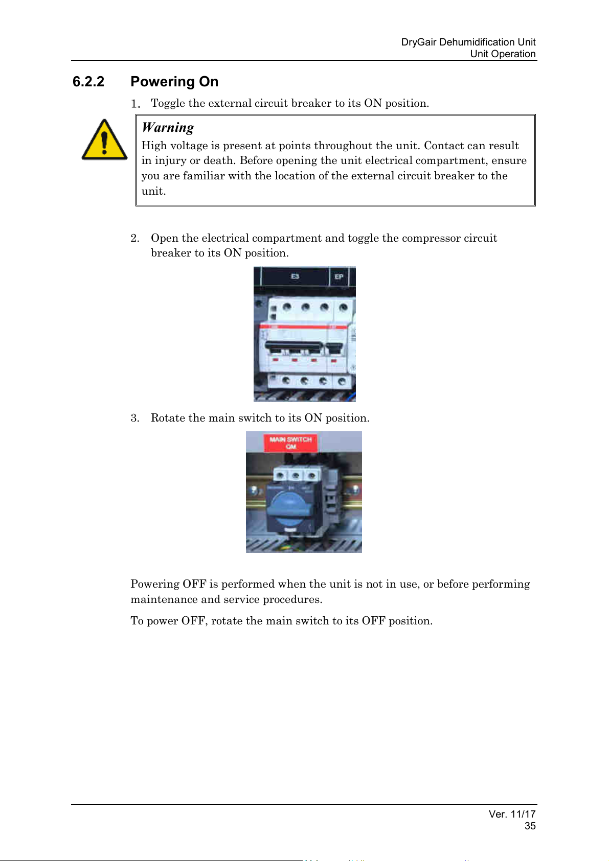
Toggle the external circuit breaker to its ON position.
2. Open the electrical compartment and toggle the compressor circuit
breaker to its ON position.
3. Rotate the main switch to its ON position.
Powering OFF is performed when the unit is not in use, or before performing
maintenance and service procedures.
To power OFF, rotate the main switch to its OFF position.
Ver. 11/17
35
Page 42
Unit Operation
Caution
Do NOT change these values without consulting DryGair Ltd.
Preparing the Unit for Operation
6.2.3 Setting the Humidity Percentage
The factory default value is around 75% RH.
To set the required Humidity percentage:
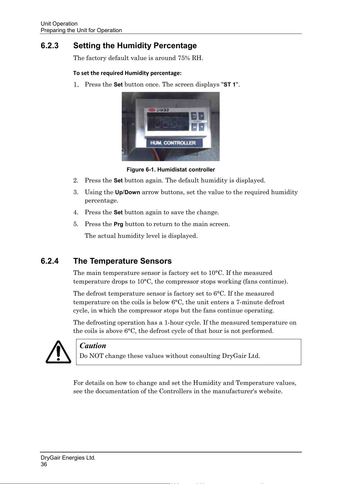
Press the Set button once. The screen displays "ST 1".
Figure 6-1. Humidistat controller
2. Press the Set button again. The default humidity is displayed.
3. Using the
Up/Down arrow buttons, set the value to the required humidity
percentage.
4. Press the
5. Press the
Set button again to save the change.
Prg button to return to the main screen.
The actual humidity level is displayed.
6.2.4 The Temperature Sensors
The main temperature sensor is factory set to 10°C. If the measured
temperature drops to 10°C, the compressor stops working (fans continue).
The defrost temperature sensor is factory set to 6°C. If the measured
temperature on the coils is below 6°C, the unit enters a 7-minute defrost
cycle, in which the compressor stops but the fans continue operating.
The defrosting operation has a 1-hour cycle. If the measured temperature on
the coils is above 6°C, the defrost cycle of that hour is not performed.
For details on how to change and set the Humidity and Temperature values,
see the documentation of the Controllers in the manufacturer's website.
DryGair Energies Ltd.
36
Page 43
DryGair Dehumidification Unit
Note
In all states, the unit should always be under power.
Unit Operation
6.2.5 Selecting the Operation Mode
The unit is turned on by a switch that has three operation modes.
• Local mode (1): the unit operates according to the values set in the
Temperature and Humidity controllers.
• Disconnected mode: unit is off
• Remote mode (2): the unit is operated and controlled by computer
software and 24 VAC that activate relays in the unit switchboard.
It should be noted that even in the Remote mode the unit stops working
when the external temperature sensor measures 10°C, and goes through
a 7-minute defrost cycle when the internal sensor measures 6°C
(according to the 1-hour defrost cycle).
Operating and controlling the unit by computer software requires the
following (not necessarily all):
1. 24VAC to start the unit (digital output from the computer). The start
parameter is set by the hours so that the unit receives a signal to operate
between the required operating hours (usually from sunset to sunrise).
This setting is performed by a climate control expert.
2. 24VAC to start dehumidification (digital output from the computer). This
condition is different from the first signal. For situations in which drying
is not required (e.g., low humidity), the circulating fans are operated
(circulating air) while the compressor is off. This is also an option for
using the fans during the day when the greenhouse is open.
For the above two signals, 3 or 4 wires are required to be connected to the
unit’s switchboard.
3. Voltage free fault outlet terminals are in the switchboard; for general
fault feedback to the software (digital input to the computer).
Two additional wires would be required for this.
Ver. 11/17
37
Page 44
Unit Operation
Note
Inspect the unit before performing first unit operation. Verify the unit is
complete and that all covers and doors are closed.
It is recommended that the first operation is performed by a qualified
DryGair person or representative.
Warning
Before clicking the START button make sure that the inside of the
machine is clear from any objects, and that there are no unauthorized
people around the machine.
Operating the Unit
6.3 Operating the Unit
Wait 2 hours after the machine is under voltage before operating.
2. Check to ensure the temperature and the humidity set points are set to
the required values. The humidity can be set through the climate control
system (if applicable).
3. Verify that the
indication light is off.
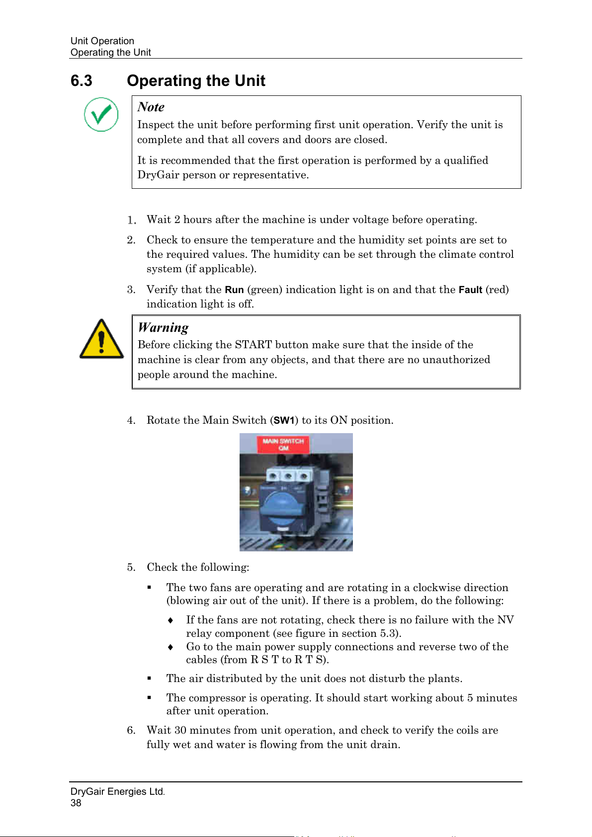
4. Rotate the Main Switch (
5. Check the following:
Run (green) indication light is on and that the Fault (red)
SW1) to its ON position.
▪ The two fans are operating and are rotating in a clockwise direction
(blowing air out of the unit). If there is a problem, do the following:
If the fans are not rotating, check there is no failure with the NV
relay component (see figure in section 5.3).
Go to the main power supply connections and reverse two of the
cables (from R S T to R T S).
▪ The air distributed by the unit does not disturb the plants.
▪ The compressor is operating. It should start working about 5 minutes
after unit operation.
6. Wait 30 minutes from unit operation, and check to verify the coils are
fully wet and water is flowing from the unit drain.
DryGair Energies Ltd.
38
Page 45
DryGair Dehumidification Unit
Caution
Maintaining the unit is very important and essential. For details, refer to
Chapter 7 –Maintaining the Unit.
Unit Operation
6.4 Operation Notes
Once the unit is operated, the unit continuously pulls the cold wet air,
dehumidifies the air and blows out drier and warmer air to the greenhouse.
The temperature and humidity of the air are set on the temperature and
humidity controllers.
• When the mode selection switch is set to Local (1), the sequence of
operation is according to the unit control panel.
• When the mode selection switch is set to Remote (2), the local humidity
controller becomes inactive, and the unit operation is controlled (start /
stop) by commands from the connected climate control unit (remote PC).
Regardless of the operation mode (local/remote), when the temperature drops
to 10°C the unit goes through a 7-minute defrost cycle every hour if the
measured coil temperature is below 6°C.
The sequence can be changed only by the DryGair technician.
The coil temperature sensor is set to around 6°C (dest. Temp.). When the
temperature is above this value the unit does not go into the defrost mode.
The Oil Heater stops operating only when the compressor starts working.
Ver. 11/17
39
Page 46
Maintaining the Unit
Warning
High voltage is present at points throughout the unit. Contact can result
in injury or death. Before opening the unit electrical compartment, ensure
you are familiar with the location of the external circuit breaker to the
unit.
Caution
Avoid direct water contact with the unit sensors!
Do not immerse them in water and/or spray direct water at them.
Warning
Before performing the following procedures, power down the unit and
disconnect the power cord.
Warning
Do not steam-clean the refrigeration coils.
Daily Maintenance
7. MAINTAINING THE UNIT
The maintenance chapter provides instructions related to periodical
maintenance and unit cleaning.
Periodic cleaning and maintenance of the unit will ensure an efficient and
long-term operation.
7.1 Daily Maintenance
Perform the following daily:
• Visually inspect the unit, verifying the unit is operating properly and
noticing if there is anything unusual.
• Clean the unit and its surroundings from any foreign material.
7.2 Monthly Maintenance
Perform the following monthly:
• The daily maintenance.
• Check to see if there are any oil stains/residues. If found, check to see the
origin and contact your local DryGair representative.
DryGair Energies Ltd.
40
Page 47
DryGair Dehumidification Unit
Caution
Do not use gasoline or solvents, which might damage the paintwork,
transparent parts, cable insulation, etc.
Caution
Do not use diesel or gasoline fuel.
Maintaining the Unit
7.2.1 Notes for Cleaning
To avoid dust build-up, the unit can be covered by material with large
ventilation holes, and should not be completely closed at its base. This is to
avoid humidity due to insufficient ventilation. Condensation will cause
rusting or corrosion of the metal parts and damage to the electrical
apparatus.
Clean carefully and dry with a clean cloth.
2. Use a vacuum cleaner to clean difficult-to-reach areas.
3. Remove oil and sludge with clean cloth. If necessary, use a paintbrush
dipped in oil, or cleaning material.
4. When the machine is idle for long period disconnect it from the power
supply.
7.3 Quarterly Maintenance
On a quarterly basis perform the following:
• The monthly maintenance.
• Clean the evaporator and condenser coils surface by gently blowing the
dirt out from behind the fins with low-pressure compressed air. Hold the
air nozzles away from the coil to avoid damage to the fins. Alternatively,
vacuum clean the coils.
You may also use a gentle brush and carefully brush the fins; if required,
use a mild detergent.
• Clean the filters and replace if required.
• Check the compressor oil level (see Figure 5-6), and change when needed.
• Check the refrigerant charge:
a. Run the unit for about 15 minutes.
b. Remove the side cover and check that there are no bubbles at the
sight glass.
c. Check that the evaporator coil is evenly wet across its surface. Partial
wetness indicates loss of refrigerant or low charge.
Ver. 11/17
41
Page 48
Maintaining the Unit
Note
It is recommended the yearly inspection and maintenance is performed by
a qualified DryGair person or representative, and having an HVAC person
or electrician for assistance.
Annual Maintenance
7.4 Annual Maintenance
On a yearly basis perform the following:
• The quarterly maintenance.
• Paint damaged or chipped body paint to preserve the unit body.
• Check that the fans are firmly secured to the motor shaft and that the fan
rotates freely. The fan motor is sealed for life and therefore does not need
to be lubricated.
• Check that the compressor isolators did not become free.
• Tighten the compressor taps and pressure switches to prevent refrigerant
leaks.
• Check the electric currents of the compressor and fans.
• Check all wiring connections, and tightened the screws if necessary
(especially in the electricity panel).
• Check the defrost unit operation (for models with a defrost mode):
▪ Switch the unit on, and leave it running for about 52 minutes.
The unit enter the air defrost mode for approximately 8 minutes
before returning to normal operation.
• Calibrate the humidity sensor. The humidity controller type is IR33,
manufactured by "CAREL" (link to product: goo.gl/kn0A3N).
DryGair Energies Ltd.
42
Page 49
DryGair Dehumidification Unit
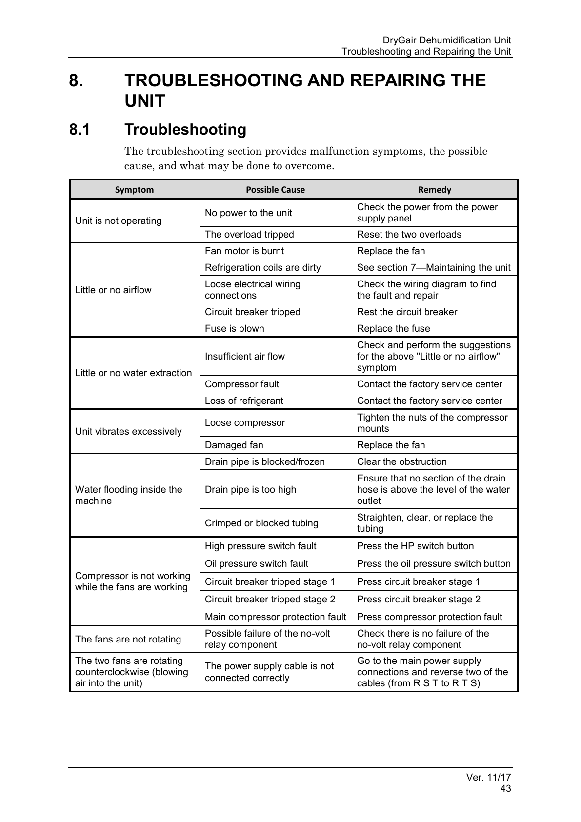
Symptom
Possible Cause
Remedy
Unit is not operating
No power to the unit
Check the power from the power
supply panel
The overload tripped
Reset the two overloads
Little or no airflow
Fan motor is burnt
Replace the fan
Refrigeration coils are dirty
See section 7—Maintaining the unit
Loose electrical wiring
connections
Check the wiring diagram to find
the fault and repair
Circuit breaker tripped
Rest the circuit breaker
Fuse is blown
Replace the fuse
Little or no water extraction
Insufficient air flow
Check and perform the suggestions
for the above "Little or no airflow"
symptom
Compressor fault
Contact the factory service center
Loss of refrigerant
Contact the factory service center
Unit vibrates excessively
Loose compressor
Tighten the nuts of the compressor
mounts
Damaged fan
Replace the fan
Water flooding inside the
machine
Drain pipe is blocked/frozen
Clear the obstruction
Drain pipe is too high
Ensure that no section of the drain
hose is above the level of the water
outlet
Crimped or blocked tubing
Straighten, clear, or replace the
tubing
Compressor is not working
while the fans are working
High pressure switch fault
Press the HP switch button
Oil pressure switch fault
Press the oil pressure switch button
Circuit breaker tripped stage 1
Press circuit breaker stage 1
Circuit breaker tripped stage 2
Press circuit breaker stage 2
Main compressor protection fault
Press compressor protection fault
The fans are not rotating
Possible failure of the no-volt
relay component
Check there is no failure of the
no-volt relay component
The two fans are rotating
counterclockwise (blowing
air into the unit)
The power supply cable is not
connected correctly
Go to the main power supply
connections and reverse two of the
cables (from R S T to R T S)
Troubleshooting and Repairing the Unit
8. TROUBLESHOOTING AND REPAIRING THE
UNIT
8.1 Troubleshooting
The troubleshooting section provides malfunction symptoms, the possible
cause, and what may be done to overcome.
Ver. 11/17
43
Page 50
Troubleshooting and Repairing the Unit
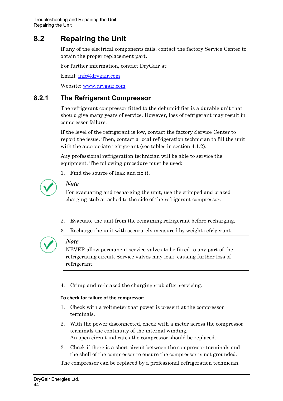
Note
For evacuating and recharging the unit, use the crimped and brazed
charging stub attached to the side of the refrigerant compressor.
Note
NEVER allow permanent service valves to be fitted to any part of the
refrigerating circuit. Service valves may leak, causing further loss of
refrigerant.
Repairing the Unit
8.2 Repairing the Unit
If any of the electrical components fails, contact the factory Service Center to
obtain the proper replacement part.
For further information, contact DryGair at:
Email:
Website: www.drygair.com
info@drygair.com
8.2.1 The Refrigerant Compressor
The refrigerant compressor fitted to the dehumidifier is a durable unit that
should give many years of service. However, loss of refrigerant may result in
compressor failure.
If the level of the refrigerant is low, contact the factory Service Center to
report the issue. Then, contact a local refrigeration technician to fill the unit
with the appropriate refrigerant (see tables in section 4.1.2).
Any professional refrigeration technician will be able to service the
equipment. The following procedure must be used:
1. Find the source of leak and fix it.
2. Evacuate the unit from the remaining refrigerant before recharging.
3. Recharge the unit with accurately measured by weight refrigerant.
4. Crimp and re-brazed the charging stub after servicing.
To check for failure of the compressor:
1. Check with a voltmeter that power is present at the compressor
terminals.
2. With the power disconnected, check with a meter across the compressor
terminals the continuity of the internal winding.
An open circuit indicates the compressor should be replaced.
3. Check if there is a short circuit between the compressor terminals and
the shell of the compressor to ensure the compressor is not grounded.
The compressor can be replaced by a professional refrigeration technician.
DryGair Energies Ltd.
44
Page 51
DryGair Dehumidification Unit
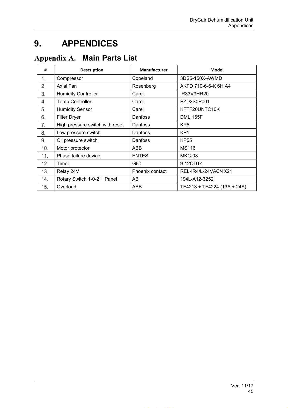
#
Description
Manufacturer
Model
Compressor
Copeland
3DS5-150X-AWMD
Axial Fan
Rosenberg
AKFD 710-6-6-K 6H A4
Humidity Controller
Carel
IR33V9HR20
Temp Controller
Carel
PZD2S0P001
Humidity Sensor
Carel
KFTF20UNTC10K
Filter Dryer
Danfoss
DML 165F
High pressure switch with reset
Danfoss
KP5
Low pressure switch
Danfoss
KP1
Oil pressure switch
Danfoss
KP55
Motor protector
ABB
MS116
Phase failure device
ENTES
MKC-03
Timer
GIC
9-12ODT4
Relay 24V
Phoenix contact
REL-IR4/L-24VAC/4X21
Rotary Switch 1-0-2 + Panel
AB
194L-A12-3252
Overload
ABB
TF4213 + TF4224 (13A + 24A)
Appendices
9. APPENDICES
Appendix A. Main Parts List
Ver. 11/17
45
Page 52
Appendices
Unit Drawings
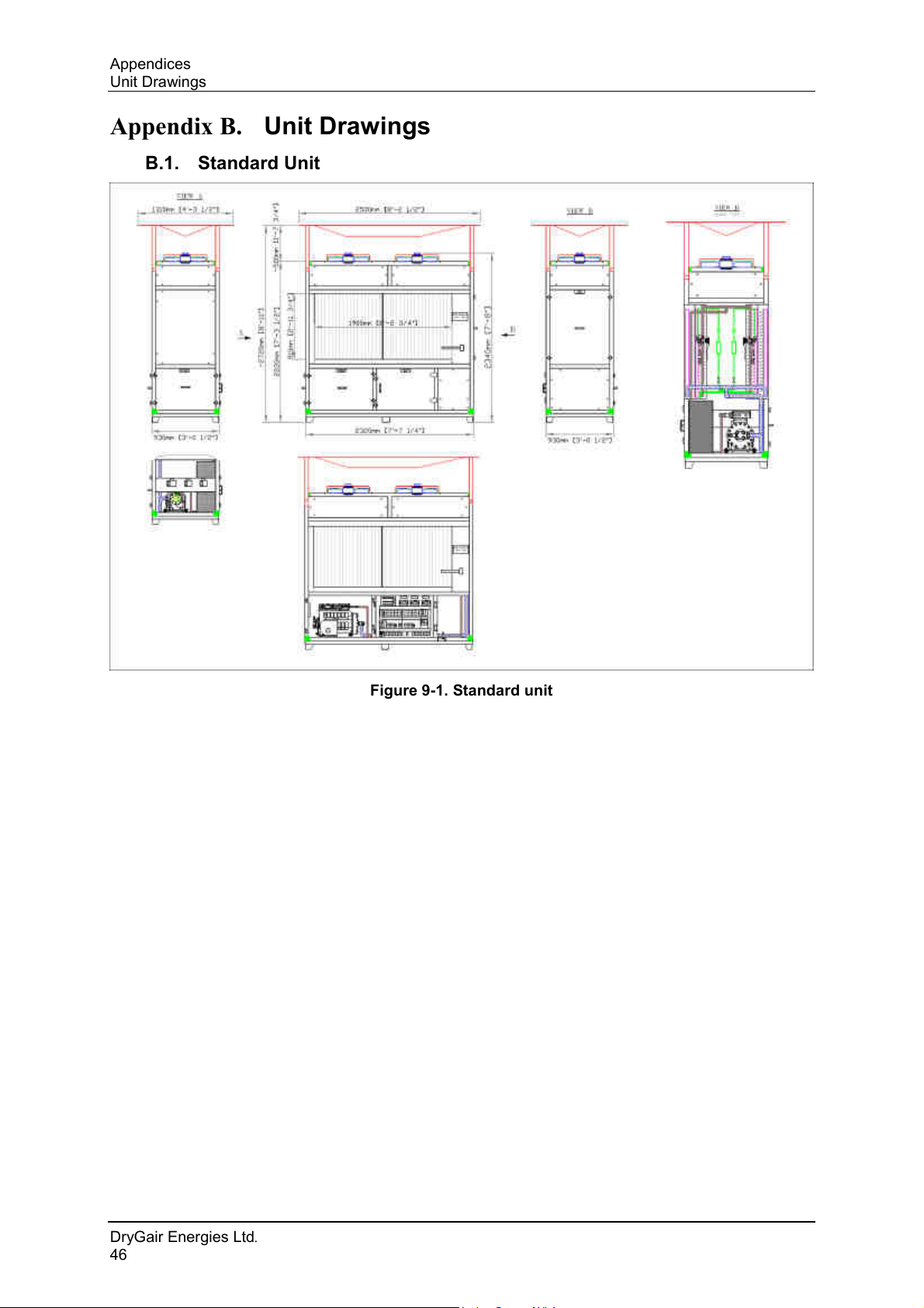
Appendix B. Unit Drawings
B.1. Standard Unit
Figure 9-1. Standard unit
DryGair Energies Ltd.
46
Page 53
DryGair Dehumidification Unit
Appendices
B.2. Small Unit
Figure 9-2. Small unit
Ver. 11/17
47
Page 54
Appendices
Unit Drawings
B.3. Standard Split Unit
Figure 9-3. Standard split unit
DryGair Energies Ltd.
48
Page 55
DryGair Dehumidification Unit
Appendices
B.4. Small Split Unit
Figure 9-4. Small split unit
Ver. 11/17
49
Page 56
Appendices
Unit Drawings
B.5. Standard Unit with Heating & Cooling
Figure 9-5. Standard unit with heating & cooling
DryGair Energies Ltd.
50
Page 57
DryGair Dehumidification Unit
Appendices
B.6. Small Unit with Heating & Cooling
Figure 9-6. Small unit with heating & cooling
Ver. 11/17
51
Page 58
Appendices
Unit Drawings
B.7. Standard Split Unit with Heating & Cooling
Figure 9-7. Standard split unit with heating & cooling
DryGair Energies Ltd.
52
Page 59
DryGair Dehumidification Unit
Appendices
B.8. Small Split Unit with Heating & Cooling
Figure 9-8. Small split unit with heating & cooling
Ver. 11/17
53
Page 60
Appendices
Unit Drawings
B.9. Warm Climate Unit
Figure 9-9. Warm climate unit
DryGair Energies Ltd.
54
Page 61
DryGair Dehumidification Unit
Note
The type of air distribution module must be pre-ordered. It cannot be
added or retrofitted on site.
Appendices
Appendix C. Air Distribution Modules (Canopy)
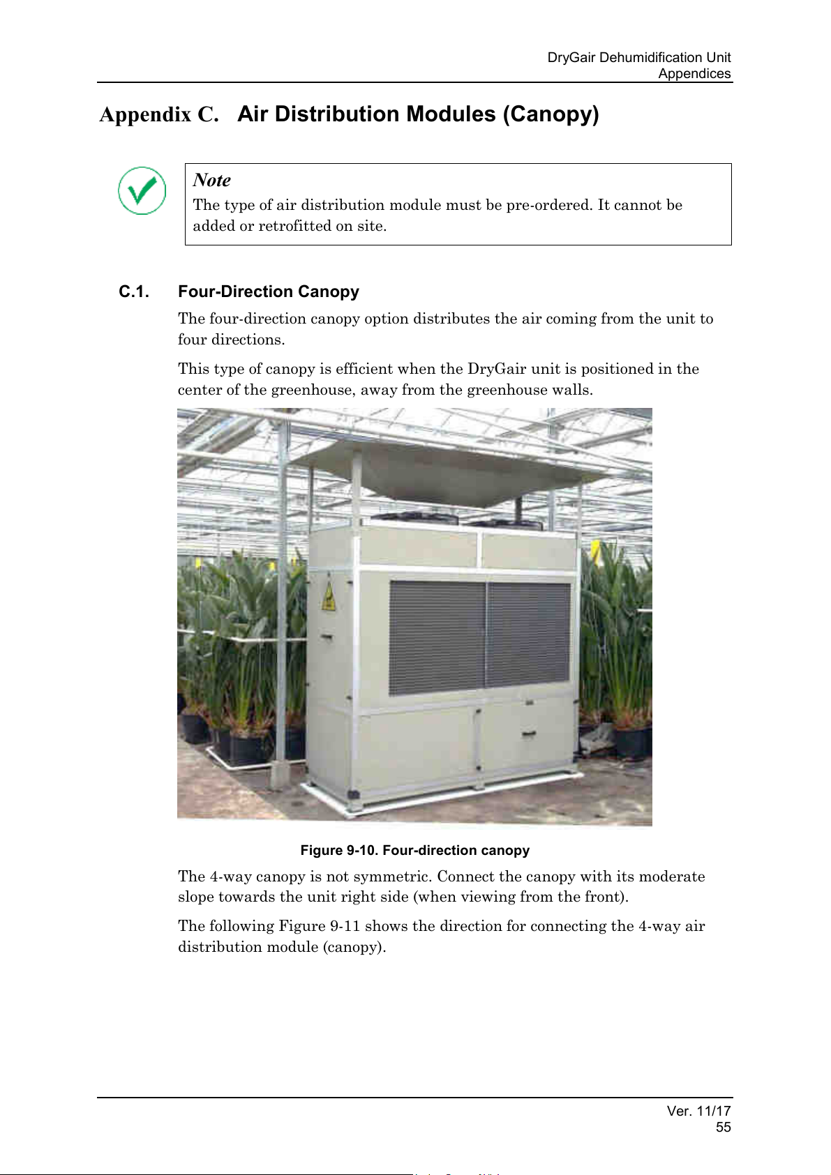
C.1. Four-Direction Canopy
The four-direction canopy option distributes the air coming from the unit to
four directions.
This type of canopy is efficient when the DryGair unit is positioned in the
center of the greenhouse, away from the greenhouse walls.
Figure 9-10. Four-direction canopy
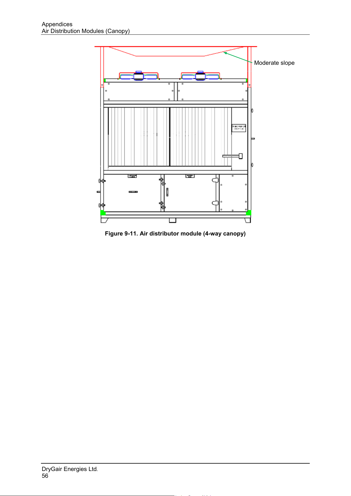
The 4-way canopy is not symmetric. Connect the canopy with its moderate
slope towards the unit right side (when viewing from the front).
The following Figure 9-11 shows the direction for connecting the 4-way air
distribution module (canopy).
Ver. 11/17
55
Page 62
Appendices
Moderate slope
Air Distribution Modules (Canopy)
Figure 9-11. Air distributor module (4-way canopy)
DryGair Energies Ltd.
56
Page 63
DryGair Dehumidification Unit
Appendices
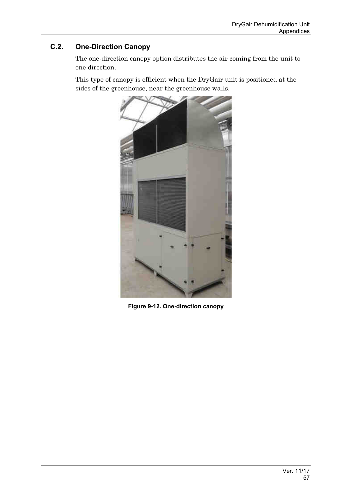
C.2. One-Direction Canopy
The one-direction canopy option distributes the air coming from the unit to
one direction.
This type of canopy is efficient when the DryGair unit is positioned at the
sides of the greenhouse, near the greenhouse walls.
Figure 9-12. One-direction canopy
Ver. 11/17
57
Page 64
Appendices
Air Distribution Modules (Canopy)
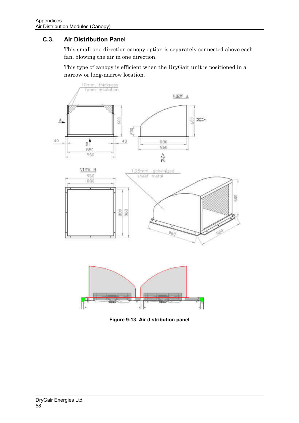
C.3. Air Distribution Panel
This small one-direction canopy option is separately connected above each
fan, blowing the air in one direction.
This type of canopy is efficient when the DryGair unit is positioned in a
narrow or long-narrow location.
DryGair Energies Ltd.
58
Figure 9-13. Air distribution panel
Page 65
DryGair Dehumidification Unit
Note
The two sections must be placed no farther than 4 meters apart.
Appendices
Appendix D. Unit Types and Configurations
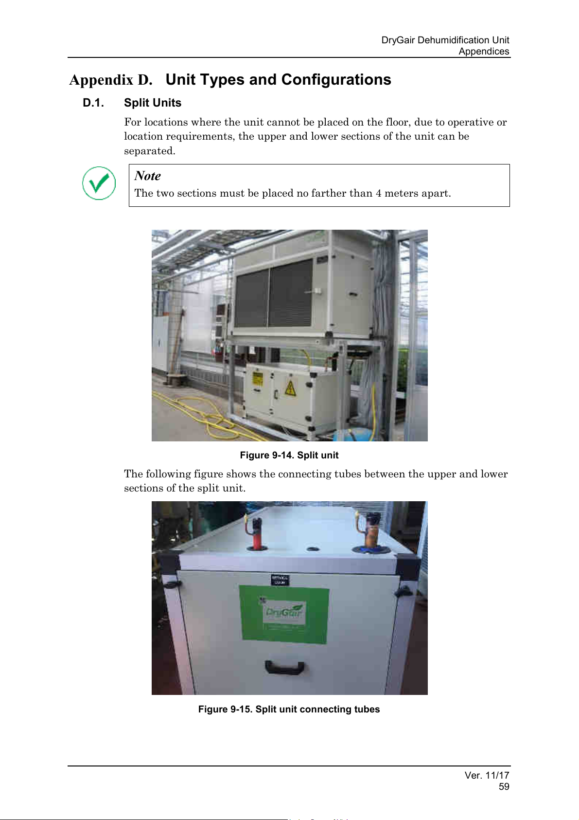
D.1. Split Units
For locations where the unit cannot be placed on the floor, due to operative or
location requirements, the upper and lower sections of the unit can be
separated.
Figure 9-14. Split unit
The following figure shows the connecting tubes between the upper and lower
sections of the split unit.
Figure 9-15. Split unit connecting tubes
Ver. 11/17
59
Page 66
Appendices
Unit Types and Configurations
D.1.1. Installing the Split Units
1. Install the split lower section in the designated location. Then, position/
hang the upper section at a distance of less than 4 meters away.
2. Connect the two sections by soldering the two copper tubes, according to
the installed line sizes.
3. Wire the electrical parts installed on the upper section to the electrical
switchboard that is part of the lower section.
4. Perform a pressure test to check for leaks. If found, repair them.
5. Perform vacuum pumping of the tubes to remove gas and moisture from
the unit tubes.
D.1.2. Preliminary Steps
1. Verify the unit is stable, installed on the rubber sheets and leveled.
2. Confirm the air distribution section is installed and well secured.
3. Confirm the drainage pipe is connected and routed, as explained in
section 4.5.1).
4. Perform a visual inspection of the unit to ensure everything is in place.
5. Confirm power supply connection (the connection shall be performed by
an authorized electrician only).
6. Turn the main switch ON to feed power to the machine.
7. Wait 30 minutes after the machine is under voltage to operate it.
8. Confirm the temp controller and the humidity controller set points are as
required.
9. Confirm the green and red lights on the phase failure/sequence relay are
illuminated.
D.1.3. Operating the Unit
Rotate the main control switch (SW1) to the desired mode of operation:
remote or local control.
D.1.4. Checking and Adjusting the Unit
1. Check that the fans are operating and rotating in the correct direction.
2. Verify the air coming from the unit is not disturbing the plants.
3. Confirm compressor operation (should start working only after 5 minutes
from operation).
4. Wait 30 minutes from operation and confirm that the coils are fully wet.
5. Adjust the expansion valves and pressure switches for optimal operation.
DryGair Energies Ltd.
60
Page 67
DryGair Dehumidification Unit
Note
This option may be used to replace the greenhouse heater or cooler.
1
2
3
4
1.
2.
3.
4.
5. Air vent
5
Appendices
D.2. Air Heating/Cooling
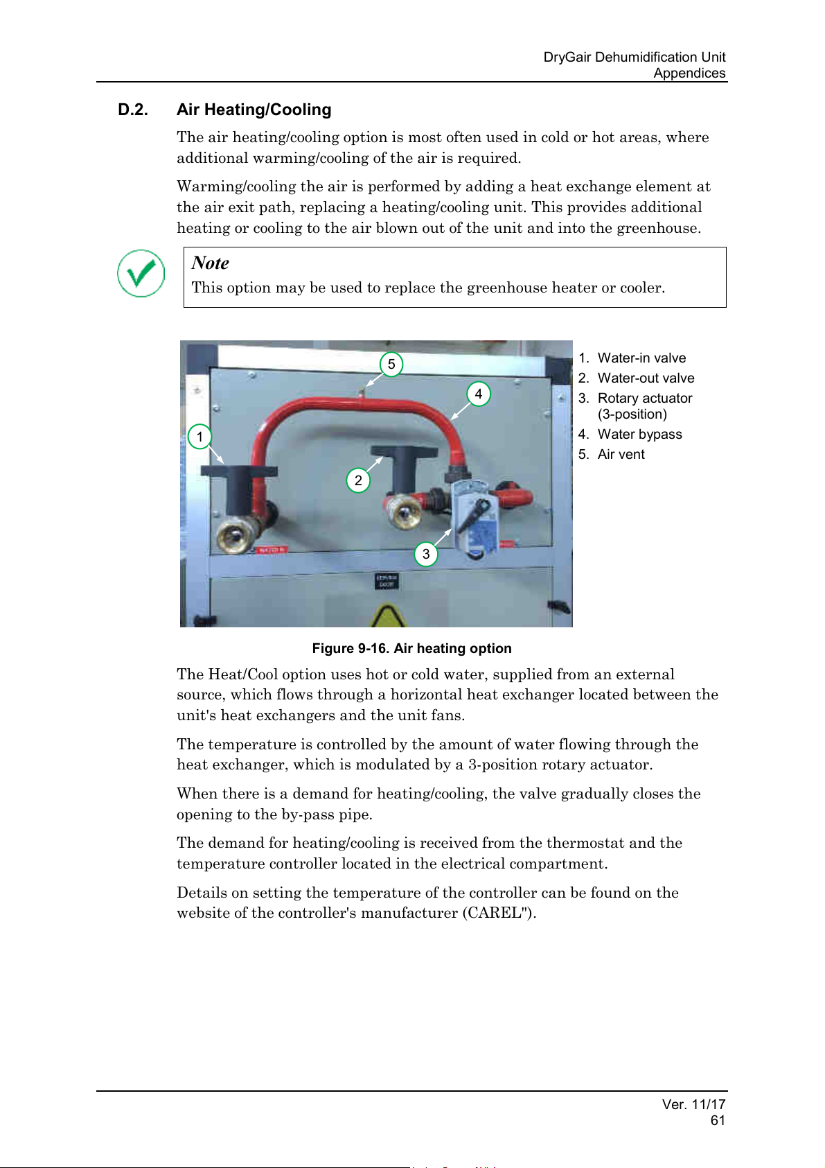
The air heating/cooling option is most often used in cold or hot areas, where
additional warming/cooling of the air is required.
Warming/cooling the air is performed by adding a heat exchange element at
the air exit path, replacing a heating/cooling unit. This provides additional
heating or cooling to the air blown out of the unit and into the greenhouse.
Water-in valve
Water-out valve
Rotary actuator
(3-position)
Water bypass
Figure 9-16. Air heating option
The Heat/Cool option uses hot or cold water, supplied from an external
source, which flows through a horizontal heat exchanger located between the
unit's heat exchangers and the unit fans.
The temperature is controlled by the amount of water flowing through the
heat exchanger, which is modulated by a 3-position rotary actuator.
When there is a demand for heating/cooling, the valve gradually closes the
opening to the by-pass pipe.
The demand for heating/cooling is received from the thermostat and the
temperature controller located in the electrical compartment.
Details on setting the temperature of the controller can be found on the
website of the controller's manufacturer (CAREL").
Ver. 11/17
61
Page 68
Comments and Notes
Unit Types and Configurations
10. COMMENTS AND NOTES
The following pages are intentionally left blank and can be used for adding
personal comments and notes related to the DryGair unit.
DryGair Energies Ltd.
62
Page 69
DryGair Dehumidification Unit
Comments and Notes
Ver. 11/17
63
Page 70

 Loading...