

Dryer Master AM3 Product Manual

Dryer Master AM
3
Product Manual
Revision 1.0 July, 2008
Revision 1.2 February, 2009
Revision 1.3 March, 2009
Revision 1.4 September, 2013
Revision 1.5 September, 2014
Revision 1.6 March, 2016
Revision 1.7 June, 2017
Prepared by:
Dryer Master Inc.
©Dryer Master Inc. 2008, 2009, 2013, 2014, 2016
Dryer Master® is a registered trademark of Dryer Master Inc.

Dryer Master AM3 Product Manual
©Dryer Master Inc. Page: 1
Table of Contents
1. INTRODUCTION ........................................................................................................................................ 7
MOISTURE MEASUREMENT TECHNOLOGY.................................................................................................................... 7
MOISTURE CONTROL TECHNOLOGY ........................................................................................................................... 7
INFORMATION DISPLAY............................................................................................................................................. 7
2. SYSTEM OVERVIEW ................................................................................................................................... 8
3 SYSTEM OPERATION ................................................................................................................................ 11
3.1 SYSTEM DISPLAYS ............................................................................................................................................ 11
3.2 SYSTEM SCREENS MAP .................................................................................................................................... 13
3.3 SYSTEM START DISPLAYS ................................................................................................................................... 14
3.4 MAIN OPERATIONS DISPLAYS ............................................................................................................................ 15
3.4.1 Main Display – Local Mode - Sensor Empty ............................................................................................ 15
3.4.2 Main Display – Local Mode ....................................................................................................................... 15
3.4.3 Main Display – Manual Mode ................................................................................................................... 15
3.4.4 Main Display – Automatic Mode .............................................................................................................. 16
3.4.5 Alarm screen ............................................................................................................................................... 16
3.4.6 Main Display – Active Alarm ..................................................................................................................... 16
3.5 MOISTURE TREND DISPLAYS .............................................................................................................................. 17
3.5.1 One Hour Moisture trend display............................................................................................................. 17
3.5.2 Two Hour Moisture trend display ............................................................................................................. 17
4 OPERATING THE DRYER FROM THE AM3 ............................................................................................... 18
4.1 OPERATING THE SYSTEM .................................................................................................................................. 18
4.1.1 Main Display – Local Mode ....................................................................................................................... 18
4.1.2 Operating Mode Select Screen .................................................................................................................. 18
4.1.3 Setting Drying Rate ..................................................................................................................................... 19
4.2 AUTO SETUP .................................................................................................................................................. 20
4.2.1 Auto Setup – Setting Speed Limits and Delay time ................................................................................. 20
4.2.2 Auto Setup –Limits and Rate Mode selection .......................................................................................... 21
4.2.3 Auto Setup – Moisture Targets, Moisture Limits and Rate Settings selection ...................................... 22
4.2.4 Auto Setup –Rate Selection Mode A.......................................................................................................... 23
4.2.5 Auto Setup –Rate Selection Mode B ......................................................................................................... 24
4.2.6 Auto Setup –Rate Selection Mode C ......................................................................................................... 25
5 THE MENU TREE ....................................................................................................................................... 26
5.1 MAIN MENUS ................................................................................................................................................. 26
5.1.1 Menu – Screen 1 ......................................................................................................................................... 26
5.1.2 Menu – Screen 2 ......................................................................................................................................... 26
5.1.3 Menu – Screen 3 ......................................................................................................................................... 26
5.1.4 Menu – Screen 4 ......................................................................................................................................... 27
5.2 CHANGE PRODUCT .......................................................................................................................................... 27
5.2.1 Menu – Screen 1 – Change Product ......................................................................................................... 27
5.2.2 Change Product .......................................................................................................................................... 27
5.3 CALIBRATE SENSOR ......................................................................................................................................... 28
5.3.1 Calibrate Sensor – Menu Selection ........................................................................................................... 28
5.3.2 Calibrate Sensor – Standard Method ...................................................................................................... 28
5.3.3 Calibrate Sensor – Enhanced Method – Start Calibration – Enter Calibration ................................... 29
5.3.4 Calibrate Sensor – Enhanced Method – Online Sample value display ................................................. 30
5.3.5 Calibrate Sensor – Enhanced Method – Sample entry ........................................................................... 30
5.4 SET ALARMS ................................................................................................................................................... 32
5.4.1 Set Alarms – Menu selection ..................................................................................................................... 32

Dryer Master AM3 Product Manual
©Dryer Master Inc. Page: 2
5.4.2 Set Alarms – Moisture Alarm values selection ........................................................................................ 32
5.4.3 Set Alarms – Temperature Alarms values selection ............................................................................... 32
5.4.4 Set Alarms – Values Entry .......................................................................................................................... 33
5.5 ALARM LOG ................................................................................................................................................... 33
5.5.1Alarm Log – Menu selection ....................................................................................................................... 33
5.5.2 Alarm Log – Data screen ........................................................................................................................... 33
5.6 ALARM DELAY ................................................................................................................................................ 34
5.6.1 Alarm Delay – Menu selection .................................................................................................................. 34
5.6.2 Alarm Delay – Data Entry selection .......................................................................................................... 34
5.6.3 Alarm Delay – Value entry ......................................................................................................................... 35
5.7 REMOTE ALARM DELAY .................................................................................................................................... 35
5.7.1 Remote Alarm Delay – Menu selection .................................................................................................... 35
5.7.2 Remote Alarm Delay – Enable & Delay entry selection .......................................................................... 36
5.7.3 Remote Alarm Delay – Value entry ........................................................................................................... 36
5.8 PRINTING ....................................................................................................................................................... 37
5.8.1 Printing – Menu selection .......................................................................................................................... 37
5.8.2 Printing – Select ID – Printing On, Off – Print Header functions ........................................................... 37
5.8.3 Printing – View ID number ........................................................................................................................ 37
5.8.4 Printing – Set ID number – Value entry.................................................................................................... 38
5.8.5 Printing – Printout sample ........................................................................................................................ 39
5.9 TEMPERATURE SCALE ....................................................................................................................................... 40
5.9.1 Temperature Scale – Menu selection ....................................................................................................... 40
5.9.2 Temperature Scale – Scale Change Warning .......................................................................................... 40
5.10 SYSTEM SETTINGS ......................................................................................................................................... 41
5.10.1 System Settings – Menu selection ........................................................................................................... 41
5.10.2 System Settings – Screen Saver – Data / Time – Contrast selection ................................................... 41
5.10.3 System Settings – Screen Saver – Items selection ................................................................................. 41
5.10.4 System Settings –Screen Saver – Timeout ............................................................................................. 42
5.10.5 System Settings – Selecting Date & Time ............................................................................................... 42
5.10.6 System Settings – Setting Date ................................................................................................................ 43
5.10.7 System Settings – Setting Time ............................................................................................................... 43
5.10.8 System Settings – Changing Display Contrast ....................................................................................... 43
5.11 ENG. FUNCTIONS .......................................................................................................................................... 44
5.11.1 Engineering Functions – Menu selection ............................................................................................... 44
5.11.2 Engineering Functions – Password Entry............................................................................................... 44
5.11.3 Engineering Functions 1 – Slope, Offset entry....................................................................................... 45
5.11.4 Engineering Functions 2 – Slope, Offset entry....................................................................................... 47
5.11.5 Engineering Functions 3 – Slope, Offset entry....................................................................................... 47
5.11.6 Engineering Functions 4 – FF&TC Corn value entry .............................................................................. 48
5.11.7 Engineering Functions 5 – TC value entry .............................................................................................. 48
5.11.8 Engineering Functions 6 – Input Voltage Diagnostics display ............................................................. 49
5.11.9 Engineering Functions 7 – Moisture sensor calibration method selection ........................................ 49
5.11.10 Engineering Functions 8 – Calibration Factor..................................................................................... 50
5.11.11 Engineering Functions 9 – Moisture Output scaling .......................................................................... 50
5.11.12 Engineering Functions 10 – Changing Temperature Scale “deg F” “deg C” ...................................... 51
5.12 LANGUAGES ................................................................................................................................................. 51
5.12.1 Languages – Menu selection ................................................................................................................... 51
5.12.2 Languages – Changing display language, English, French, Spanish................................................... 52
5.13 TRENDING OPTIONS ...................................................................................................................................... 53
5.13.1 Trending Options – Menu selection ....................................................................................................... 53
5.13.2 Trending Options – Clearing data .......................................................................................................... 53
5.13.3 Trending Options – Changing Moisture range ...................................................................................... 53
5.13.4 Trending Options – Changing trend time scale .................................................................................... 54

Dryer Master AM3 Product Manual
©Dryer Master Inc. Page: 3
5.14 INFORMATION .............................................................................................................................................. 54
5.15 REMOVABLE MEDIA ....................................................................................................................................... 54
5.16 AUTO SETUP ................................................................................................................................................ 55
6 DISPLAY UNIT INSTALLATION................................................................................................................ 56
6.1 PANEL MOUNT (SELF-INSTALL) ......................................................................................................................... 56
6.1.1 Display Dimensions ................................................................................................................................... 56
6.1.2 Display Panel cut out ................................................................................................................................. 57
6.1.3 Display (PLC) Electrical Connections ........................................................................................................ 58
6.1.4 Field Electrical Connections ...................................................................................................................... 59
6.2 AM
3
PANEL ................................................................................................................................................... 60
6.2.1 In Panel Electrical Connections ................................................................................................................ 60
6.2.2 Field Electrical Connections ...................................................................................................................... 61
6.3 PRINTING OPTION ........................................................................................................................................... 62
7 MOISTURE SENSOR GENERAL SPECIFICATIONS ................................................................................... 63
7.1 MOISTURE SENSOR INSTALLATION .................................................................................................................... 63
7.1.1 Moisture Range & Temperature range. ................................................................................................... 63
7.1.2 Sensor signal conversion ........................................................................................................................... 63
7.2 2200-11-BTC-RB, Fin Sensor ......................................................................................................................... 64
7.2.1 Sensor Power requirements ...................................................................................................................... 65
7.2.2 Grounding ................................................................................................................................................... 65
7.2.3 Signal Output .............................................................................................................................................. 65
7.2.4 Sensor Not Reading Empty with no product present ............................................................................. 65
7.3 SENSOR SETUP & DIAGNOSTICS ......................................................................................................................... 65
8 INSTALLATION REQUIREMENTS & SPECIFICATIONS ........................................................................... 67
8.1 BYPASS CHUTE INSTALLATION EXAMPLES ........................................................................................................... 68
8.1.1 Bypass Chute Installation square chute with screw metering .............................................................. 68
8.1.2 Bypass Chute Installation round chute with screw metering ................................................................ 69
8.1.3 Bypass Chute metering screw ................................................................................................................... 70
8.1.4 Bypass Chute screw metering RPM table ................................................................................................ 71
8.1.5 Bypass Chute Installation rotary valve or airlock metering .................................................................. 72
8.1.6 Bypass Chute rotary valve or airlock metering RPM table .................................................................... 72
8.1.7 Bypass Chute Example .............................................................................................................................. 74
8.1.8 Bypass Chute Example: Dimensions ........................................................................................................ 74
8.1.9 Bypass Chute Example feeding back on itself ......................................................................................... 75
8.1.10 Bypass Chute Example mechanical metering ....................................................................................... 76
8.2 IN LINE CHUTE INSTALLATION EXAMPLES ........................................................................................................... 77
8.2.1 In Line Chute Example mechanical metering ......................................................................................... 77
8.2.2 In Line Chute Example: Dimensions ......................................................................................................... 78
9 APPENDIX A .............................................................................................................................................. 79
9.1 HISTORY & CALIBRATION FILES DATA FORMAT .................................................................................................... 79
9.1.1History data example ................................................................................................................................. 79
9.1.2 Calibration data example ......................................................................................................................... 80
10 APPENDIX B – WARRANTY .................................................................................................................... 81
11 APPENDIX C - IMO SET-UP GUIDE ........................................................................................................ 82
12 APPENDIX D. SENSOR CHUTE W/ ROTARY FEED ................................................................................ 87
13 APPENDIX E MOTOR SPEED CONTROL WIRING DIAGRAM ............................................................... 89

Dryer Master AM3 Product Manual
©Dryer Master Inc. Page: 4
List of Figures and Tables
Figure 1. – Typical System with enhanced display and options 8
Figure 2. – Typical System with standard display mounted in Dryer Control panel and options 9
Figure 3. – Information display 10
Figure 4. – Fin Moisture sensor 10
Figure 5. – Information display in enclosure 10
Figure 6. –System display items description. 11
Figure 7. –Screen map 13
Figure 8. –Startup diagnostics display 14
Figure 9. –Product information display 14
Figure 10. –Main Display 14
Figure 11. –Main Display – Sensor Empty, 15
Figure 12. –Main Display – Local Mode 15
Figure 13. –Main Display – Manual Mode 15
Figure 14. –Main Display – Automatic Mode 16
Figure 15. –Alarm screen 16
Figure 16. –Main Display – Active Alarm 16
Figure 17. –One (1) hour Moisture Trend 17
Figure 18. –Two (2) hour Moisture Trend 17
Figure 19. –Main Display 18
Figure 20. –Mode Select screen 18
Figure 21. –Drying rate setting screen 19
Figure 22. – Auto Setup – Speed limits and delay time 20
Figure 23. – Auto Setup – Limits and Rate mode selection 21
Figure 24. – Auto Setup – Moisture targets, Moisture Limits and Rate settings selection 22
Figure 28. –Menu One (1) 26
Figure 29. –Menu Two (2) 26
Figure 30. –Menu Three (3) 26
Figure 31. –Menu Four (4) 27
Figure 32. –Menu One (1) – Change Product 27
Figure 33. – Change Product 27
Figure 34. – Calibrate Sensor 28
Figure 35. – Calibrate Sensor (Standard method) 28
Figure 36. – Calibrate Sensor (Enhanced method) Start & Enter 29
Figure 37. – Calibrate Sensor (Enhanced method) Sample Display 30
Figure 38. – Calibrate Sensor (Enhanced method) Sample Entry 30
Figure 39. – Set Alarms 32
Figure 40. – Set Alarms – Moisture Alarms values selection 32
Figure 41. – Set Alarms – Temperature Alarms 32
Figure 42. – Set Alarms – Value Entry 33
Figure 43. – Alarm Log 33
Figure 44. – Alarm Log – Data screen 33
Figure 45. – Alarm Delay 34
Figure 46. – Alarm Delay –Entry selection 34
Figure 47. – Alarm Delay – Value Entry 35
Figure 48. – Remote Alarm Delay 35
Figure 49. – Remote Alarm Delay – Enable & Entry selection 36
Figure 50. – Remote Alarm Delay – Value Entry 36

Dryer Master AM3 Product Manual
©Dryer Master Inc. Page: 5
Figure 51. – Printing 37
Figure 52. – Printing – Enable, Set ID & Print Header selection 37
Figure 53. – Printing – Set ID 37
Figure 54. – Printing – ID Value Entry 38
Figure 55. – Printing – Information example and explanation. 39
Figure 56. – Temperature Scale 40
Figure 57. – Temperature Scale change Warning 40
Figure 58. – System Settings 41
Figure 59. – System Settings – Items Selection 41
Figure 60. – System Settings – Screen Saver – Items Selection 41
Figure 61. – System Settings – Screen Saver – Time delay entry 42
Figure 66. – Engineering Functions 44
Figure 67. – Engineering Functions – Password 44
Figure 68. – Engineering Functions – Password Entry 44
Figure 69. – Engineering Functions 1 – Slope, Offset entry 45
Figure 70. – Engineering Functions 2 – Slope, Offset entry 47
Figure 71. – Engineering Functions 3 – Slope, Offset entry 47
Figure 72. – Engineering Functions 4 – FF & TC Corn value entry 48
Figure 73. – Engineering Functions 5 – TC value entry 48
Figure 74. – Engineering Functions 6 – Input Voltage diagnostics display 49
Figure 75. – Engineering Functions 7 – Calibration Method screen 49
Figure 76. – Engineering Functions 8 – Calibration Factor screen 50
Figure 87. –Display Dimensions 56
Figure 88. –Display Panel cutout 57
Figure 89. –Display Electrical connections 58
Figure 90. –Electrical connections Field devices 59
Figure 91. –AM3 In Panel connection terminal strip 60
Figure 92. –Electrical connections Field devices 61
Figure 93. –Moisture Sensor 64
Figure 94. –Sensor Setup & diagnostics 66
Figure 95. –Moisture Sensor Bypass Chute design #1 square pipe 68
Figure 96. –Moisture Sensor Bypass Chute design #2 round pipe 69
Figure 97. –Moisture Sensor Bypass Chute conceptual metering screw design 70
Figure 98. – Table of metering device RPM – screw conveyor 71
Figure 99. –Moisture Sensor, Example of a Sample Bypass Installation 72
Figure 100. – Table of metering device RPM – rotary airlock or rotary valve 72
Figure 101. –Moisture Sensor, Example of a bypass Chute Installation 73
Figure 102. –Bypass Chute Example 74
Figure 103. –Bypass Chute Example: Dimensions 74
Figure 104. –Moisture Sensor, Example of a bypass Chute Installation, product feeding back on itself 75
Figure 106. –In Line Chute Example 77
Figure 107. –In Line Chute Example: Dimensions 78
Figure 108. –History file data format 79
Figure 109. –Calibration file data format 80

Dryer Master AM3 Product Manual
©Dryer Master Inc. Page: 6
To Our Customer
Thank you for purchasing the Dryer Master AM3 (Automatic Mini Moisture Manager) System. The
Dryer Master AM3 is a robust system that employs state logic for control. It is simple to use and can be
applied to most if not all grain moisture measurement applications.
The AM3 is part of the Dryer Master family of moisture monitoring and moisture control systems that
have at their heart Dryer Master's stainless steel fin type capacitance based moisture sensors. These
sensors were initially developed to drive Dryer Master's industry leading computerized moisture
control systems, where they are placed at the inlet and the outlet of the dryer. With over 30 years of
field proven experience they are now being offered as part of the AM3 moisture monitoring and state
logic control solution.
We trust that you will be pleased with the operation of the AM3 and that you will enjoy benefits similar
to those provided by the world renowned Dryer Master moisture control system.
Dryer Master Inc.

Dryer Master AM3 Product Manual
©Dryer Master Inc. Page: 7
1. Introduction
This document provides the operational specification for an on-line moisture display system with a
single sensor; product moisture and product temperature are displayed. Moisture control is achieved
using state logic. The system consists of a display unit and a moisture sensor. Both the display unit
and the sensor require less than 15 watts of power and are powered from a low voltage 24-volt direct
current instrumentation power supply. Depending on the options purchased the system may include
other components and devices.
Moisture measurement technology
The Dryer Master Moisture sensor measures the dielectric properties, in effect the capacitance of the
product in the vicinity of the sensor fin. This method is the most effective in measuring the total water
in a given volume of product. The installation ensures a large sample of product is presented to the
sensor at all times. This large sample contributes to a better product moisture representation than
other methods and generally provides a very good representation of the product in the total sample
stream. This technology is particularly suited to the measurement of product with moisture gradients.
A moisture gradient occurs any time product is processed either by heating or cooling but not limited
to either. The sensor’s robust construction and conservative installation specifications ensure long
product life.
Moisture control technology
The Dryer Master AM3 state control technology employs a 3 state model triggered by user settable
moisture targets, time delays and speed set points for continues dryers. Instead of constantly
switching between a high and low discharge speed as used in many smaller on farm drying systems the
system switches between higher discharge speed triggered by drier product to normal speed, to lower
speed triggered by higher moisture product. Depending on the operating mode the 3 speeds can be
either individually manually set, set as a % of the normal operating speed, or a specific deviation from
the normal speed. The trigger points are actual moistures measured by the moisture sensor and
delays to activation are user settable from 1 second to 999 seconds or 16.65 minutes. The system can
also be configured for recirculation batch type dryers. Where the product is re- circulated in the dryer
until a specific moisture target is reached and the dryer is unloaded.
Information display
The information display is a micro PLC (Programmable Logic Controller) with an integrated graphics
LCD display and keypad. This combination of integrated items is also referred to as an OCS (Operator
Control Station). The Dryer Master Moisture sensor calibration software embedded in this device
provides the same reliability and accuracy previously once only available in the Dryer Master dryer
control systems.
Dryer Master AM3 Product Manual
©Dryer Master Inc. Page: 8
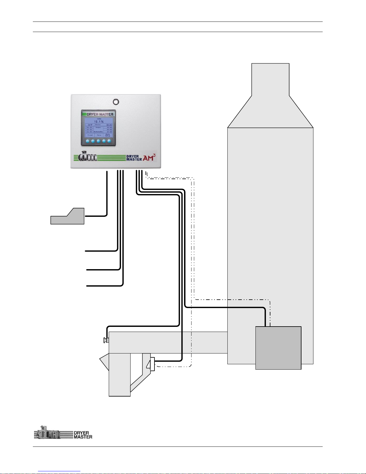
Optional
Printer
Outlet Moisture
&
Temperature
Sensor
Optional Moisture
Sample Start Button
Dryer Control
Panel
(
Discharge
Speed
)
DRYER
Instrumentation
cables
Ground
cables
24
vdc time delayed
Remote alarm output
24
vdc time delayed
alarm output
0 – 10
Volt Moisture
signal output to
Automation system
2. System Overview
The system is comprised of 2 key elements, the industry proven Dryer Master Moisture sensor and a
Micro PLC with integrated touch screen information display.
Figure 1. – Typical System with enhanced display and options
Dryer Master AM3 Product Manual
©Dryer Master Inc. Page: 9
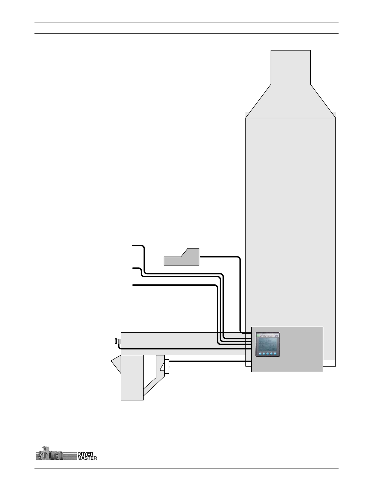
Figure 2. – Typical System with standard display mounted in Dryer Control panel and options
Optional
Printer
Outlet Moisture
&
Temperature
Sensor
Optional Moisture
Sample Start Button
Dryer Control
Panel
(
Discharge
Speed
)
DRYER
24
vdc time delayed
Remote alarm output
24
vdc time delayed
alarm output
0 – 10
Volt Moisture
signal output to
Automation system
Dryer Master AM3 Product Manual
©Dryer Master Inc. Page: 10
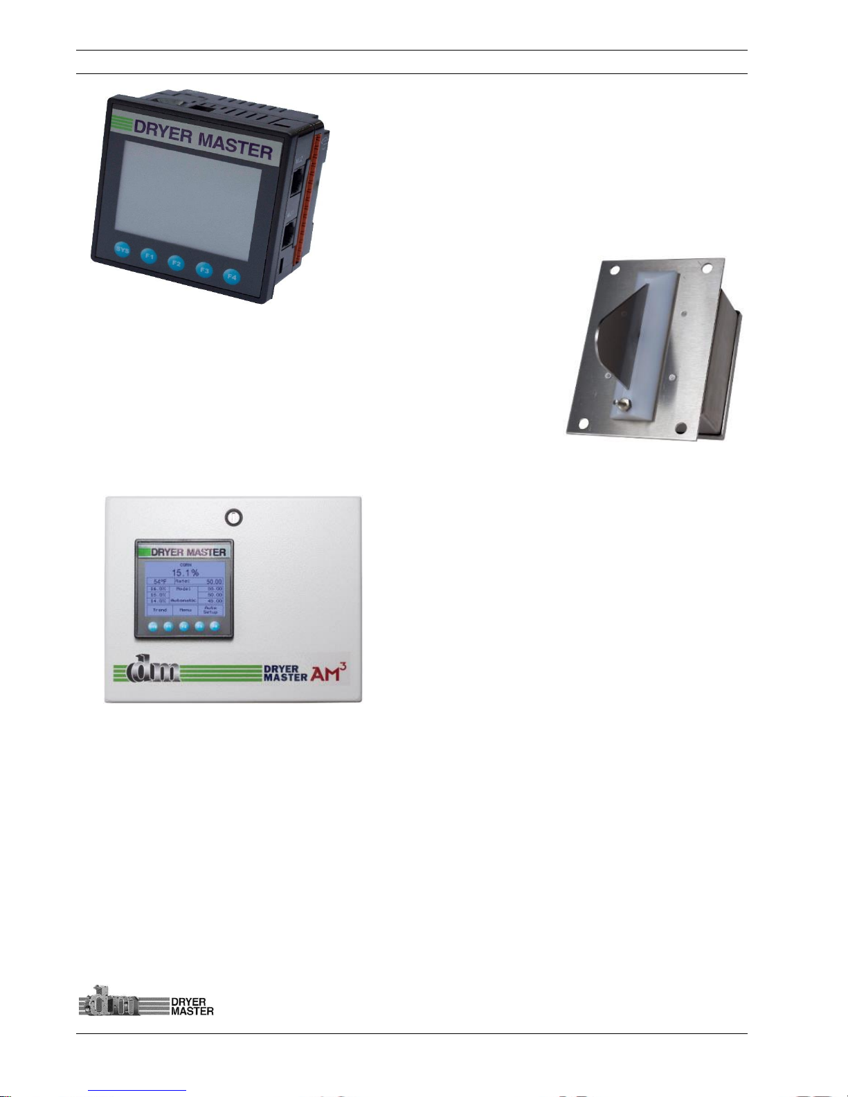
1. The Display unit is the information provider. Product
moisture, product temperature as well as alarms and moisture
trends are information continuously displayed. Product
selection, Discharge Rate settings, as well as sensor calibration,
alarm function and system setup are all functions accomplished
through menus accessed via the key pad and Action Keys. The
display has a screen saver that shuts down the back lighting to
prolong lamp life.
Figure 3. – Information display
2. The Moisture sensor is the heart of the system. The sensor is
located in what is called a compacted product flow situation. This is
a chute where the product is slowed and allowed to compact. The
sensor measures the free water in the product in this chute. Even
and consistent product flow is key to obtaining stable moisture
readings.
Figure 4. – Fin Moisture sensor
3. The enhanced system adds an enclosure for the
display unit, easy to connect terminals and a universal
voltage system power supply to power both the Display
and Moisture sensor. The supply may also be used to
activate low voltage low current alarm devices or alarm
contacts. On systems equipped with a Dryer Master
Power supply the unit is capable of supplying 24Volts DC
at up to 1 Amp and is current limited and designed to
shut down in the event of a short circuit.
Figure 5. – Information display in enclosure
4. The optional industrial grade point of sale terminal printer provides hard copy records of
operation with a record printed every 10 minutes.
5. A calibrations pushbutton may also be used. This illuminated push button when installed
and configured can assist moisture calibration by automating this function. When so
configured the system will gather and average the moisture passing by the sensor during the
period the button lamp is flashing, and then remain lit until the calibration result is entered.
6. Alarm outputs with time delay settings can be used sound alarm devices and or trigger
events.
Dryer Master AM3 Product Manual
©Dryer Master Inc. Page: 11
3 System Operation
This section will deal with the most common items needed to operate the unit. Included is a screen
map of the various screens displayed during start up and operation when alarm conditions occur,
continuing on to product selection and sensor calibration. Also included in this section are common
setup functions such as alarm limit settings, alarm action settings and common system settings. The
detailed Engineering and device setup functions will be described in another section.
3.1 System displays
This is a Touch screen system. Throughout this document there may be references to “Touch Keys” or
“Touch areas” which refer to values or text on the LCD display. These “Touch Keys” or “Touch areas”
will access various functions as you navigate through the screens & menus. The Display may also be
referred to as a PLC (Programmable Logic Controller) or an OCS (Operator Control Station).
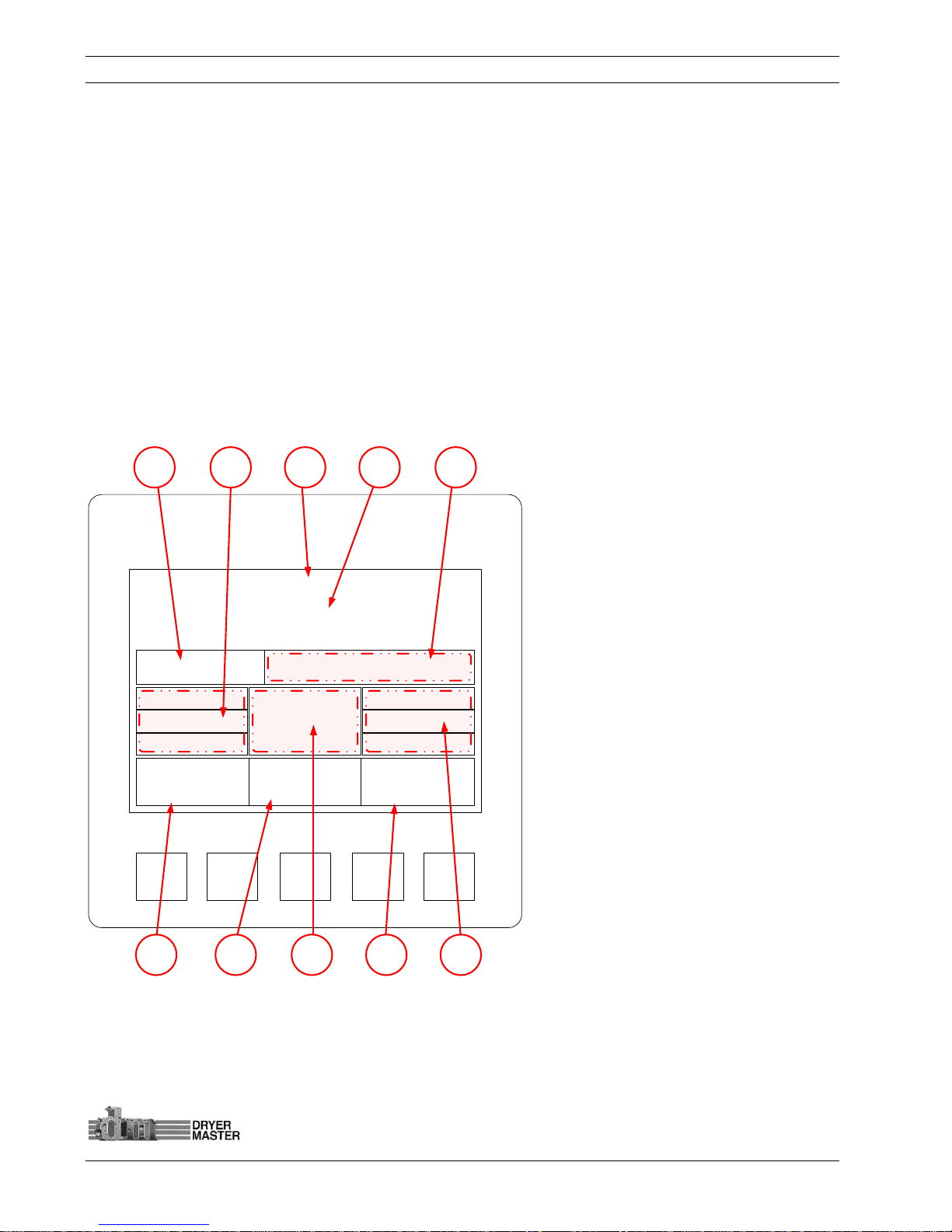
Figure 6. –System display items description.
SYSTEM
F1 F2 F3 F4
Corn
15.1%
Mode:
Manual
75 °F Rate: 50.00
Trend Menu
Auto
Setup
16.0%
15.0%
14.0%
55.00
50.00
45.00
3 4 51 2
9 810 7 6

Dryer Master AM3 Product Manual
©Dryer Master Inc. Page: 12
Product Temperature: Actual temperature of product as detected by the Moisture sensor
temperature probe.
Moisture targets: Indicates, top to bottom “High” moisture trip point, “Target” moisture,
“Low” moisture trip point. This is an active touch area. Press to change values.
Product Name: This is the currently selected product. The text is replaced by an alarm
indicator in the event either the product temperature or product moisture is in alarm.
Product Moisture display: Actual moisture of the product as detected by the Dryer Master
Moisture sensor. Note this will indicate “Empty” when the sensor output is below critical trigger
threshold either by being empty, not connected or moisture so low that reading is not possible.
Rate: Discharge Rate Set point. This is the speed signal sent to the Dryers Discharge system.
This value is displayed when the dryer speed selection is switched to the AM3 (Manual or
Automatic). This is an active touch area. Press to change values.
Rate Targets: Indicates, top to bottom “High” rate value triggered by low moisture trip point,
“normal” Rate, “Low” rate value triggered by high moisture trip point. This is an active touch
area. Press to change values.
Auto Setup Touch key: Use to set operating limits and Auto modes.
Mode: Operating Mode, choices are “Local”, Speed set at the Dryers Speed potentiometer or
display, “Manual” Speed is set manually at the AM3, “Automatic” Speed set point is Automatic
via the programmed settings.
Menu: Product selection, Sensor calibrations, Alarms and others are available through the
Menu screens.
Trend: Switches to current operation trend graph.
1234568910
7
Dryer Master AM3 Product Manual
©Dryer Master Inc. Page: 13
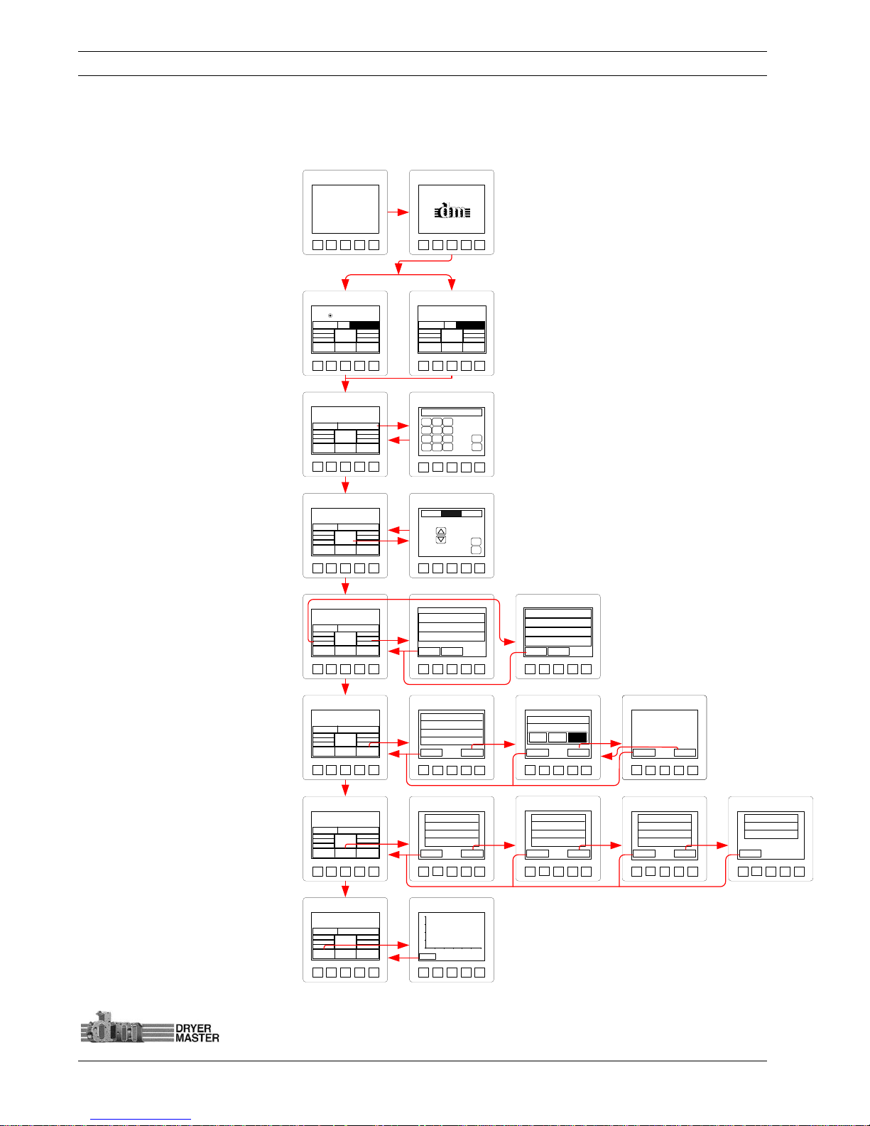
3.2 System Screens Map
This screens map shows the first layer screens available from the Main display. In-depth description and
navigation is detailed in the document.
Start-up “Self Test”
System Information
Main Operations Screens
Main Operations Screen,
setting discharge rate while in
MANUAL mode.
Main Operations Screen,
changing operations modes
Main Operations Screen,
changing Moisture targets and
trip points as well as operating
speeds
Main Operations Screen,
navigating Auto Setup.
Main Operations Screen,
navigating the Menu.
Main Operations Screen,
selecting the Trend displays
Figure 7. –Screen map
SYSTEM
F1
F2 F3 F4
XT105N
*** Self-Test Passed ***
SYSTEM
F1
F2 F3 F4
AM3
Grain
Moisture
Control System
by
Dryer Master
SYSTEM
F1
F2 F3 F4
0.00
_QZ
1
ABC2DEF
3
GHI4JKL5MNO
6
PRS7TUV
8
WXY
9
0+ / -
.
Esc
Enter
SYSTEM
F1
F2 F3 F4
Automatic
Esc
Enter
SYSTEM
F1
F2 F3 F4
Exit
Next
Max Safe Speed 100.00
Min Safe Speed 10.00
Hi/Low Delay Time 300s
Norm Spd Delay Time 300s
SYSTEM
F1
F2 F3 F4
Exit
Help
Max Safe Speed 100.00
MODE A
MODE CMODE B
Rate Mode Select
SYSTEM
1 QZ
F1
2 ABCF23 DEFF34 GHI
F4
Exit
Help
Max Safe Speed 100.00
MODE A
MODE CMODE B
Rate Mode Select
SYSTEM
F1
F2 F3 F4
Exit
Back
Mode A: All speeds set manually.
Mode B: “H/L Rate Change” setting
determines high and low speeds.
Mode C: “Rate Change” determines
high and low speeds.
See manual for further info.
SYSTEM
F1
F2 F3 F4
Exit
Next
F1 Change Product
F2 Calibrate Sensor
F3 Set Alarms
F4 Alarm Log
SYSTEM
F1
F2 F3 F4
Exit
Next
F1 Alarm Delay
F2 Remote Alm Delay
F3 Printing
F4 Temp. Scale
SYSTEM
F1
F2 F3 F4
Exit
F1 Information
F2 Removable Media
F3 Auto Setup
SYSTEM
F1
F2 F3 F4
Exit
Next
F1 System Settings
F2 Eng. Functions
F3 Languages
F4 Trending Options
SYSTEM
F1
F2 F3 F4
Exit
2
0
%
1
0
Time (10min/DIV)
SYSTEM
F1 F2 F3 F4
CORN
75 °F
Rate: 10.00
Trend Menu
Auto
Setup
See Dryer
Mode:
Local
16.0%
15.0%
14.0%
55.00
50.00
45.00
Empty
SYSTEM
F1 F2 F3 F4
CORN
15.0%
75 °F
Rate: 10.00
Trend Menu
Auto
Setup
See Dryer
Mode:
Local
16.0%
15.0%
14.0%
55.00
50.00
45.00
SYSTEM
F1 F2 F3 F4
CORN
15.1%
Mode:
Manual
75 °F Rate: 50.00
Trend Menu
Auto
Setup
16.0%
15.0%
14.0%
55.00
50.00
45.00
SYSTEM
F1 F2 F3 F4
CORN
15.1%
Mode:
Manual
75 °F Rate: 50.00
Trend Menu
Auto
Setup
16.0%
15.0%
14.0%
55.00
50.00
45.00
SYSTEM
F1 F2 F3 F4
CORN
15.1%
Mode:
Manual
75 °F Rate: 50.00
Trend Menu
Auto
Setup
16.0%
15.0%
14.0%
55.00
50.00
45.00
SYSTEM
F1 F2 F3 F4
CORN
15.1%
Mode:
Manual
75 °F Rate: 50.00
Trend Menu
Auto
Setup
16.0%
15.0%
14.0%
55.00
50.00
45.00
SYSTEM
F1 F2 F3 F4
CORN
15.1%
Mode:
Manual
75 °F Rate: 50.00
Trend Menu
Auto
Setup
16.0%
15.0%
14.0%
55.00
50.00
45.00
SYSTEM
F1 F2 F3 F4
CORN
15.1%
Mode:
Manual
75 °F Rate: 50.00
Trend Menu
Auto
Setup
16.0%
15.0%
14.0%
55.00
50.00
45.00
SYSTEM
F1 F2 F3 F4
Exit
Normal Rate 50.00
High Rate 55.00
Low Rate 45.00
Back
SYSTEM
F1 F2 F3 F4
Exit
Target Moisture 15.0%
High Moist. Limit 16.0%
Low Moist. Limit 14.0%
Rate Settings
Back
Dryer Master AM3 Product Manual
©Dryer Master Inc. Page: 14
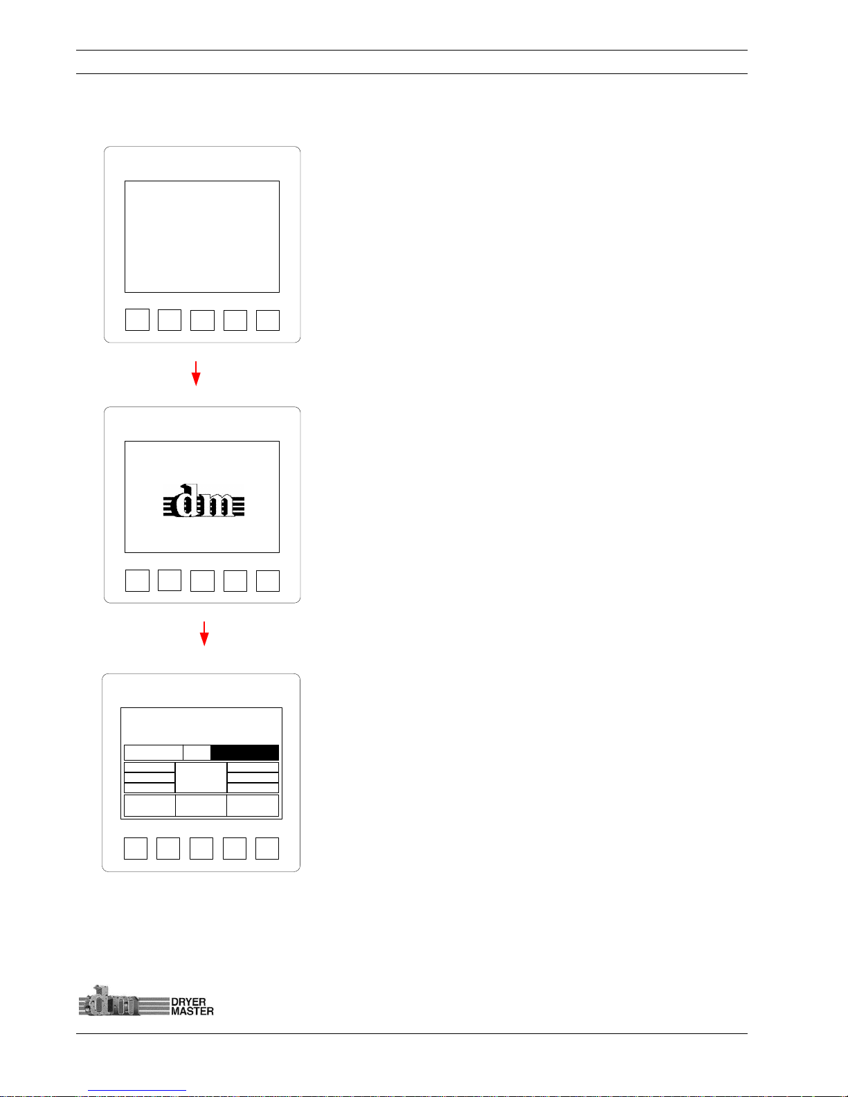
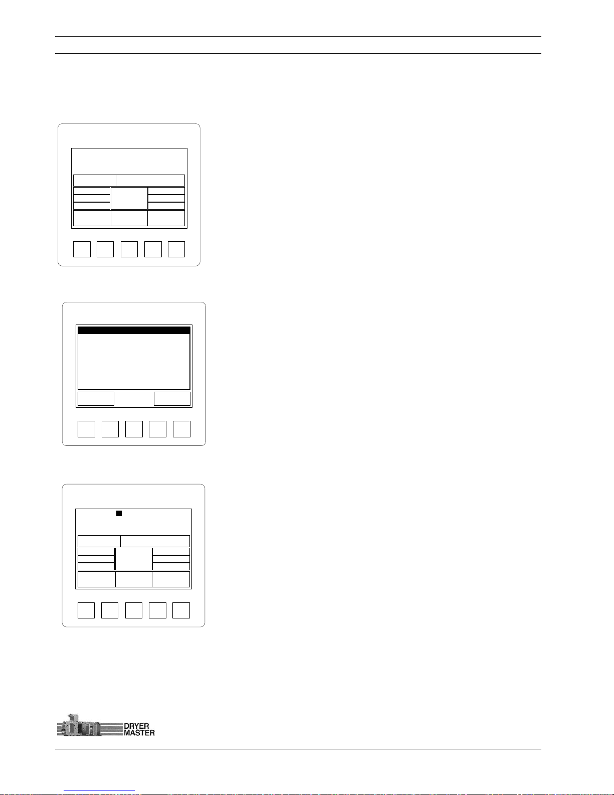
3.3 System start displays
At System start the unit will display the start-up diagnostic screen.
Figure 8. –Start-up diagnostics display
Once the diagnostics are complete the unit will execute the
installed program, during this time the product information screen
will display.
Figure 9. –Product information display
The Main Operations screen displays product moisture, product
name, product temperature, and Dryer discharge rate when in
Manual or Auto Mode.
Depending on the system state, different information may be
displayed
Figure
10.
–Main Display
SYSTEM
F1
F2 F3 F4
XT105N
*** Self-Test Passed ***
SYSTEM
F1
F2 F3 F4
AM3
Grain
Moisture
Control System
by
Dryer Master
SYSTEM
F1 F2 F3 F4
CORN
15.0%
75 °F
Rate: 10.00
Trend Menu
Auto
Setup
See Dryer
Mode:
Local
16.0%
15.0%
14.0%
55.00
50.00
45.00
Dryer Master AM3 Product Manual
©Dryer Master Inc. Page: 15
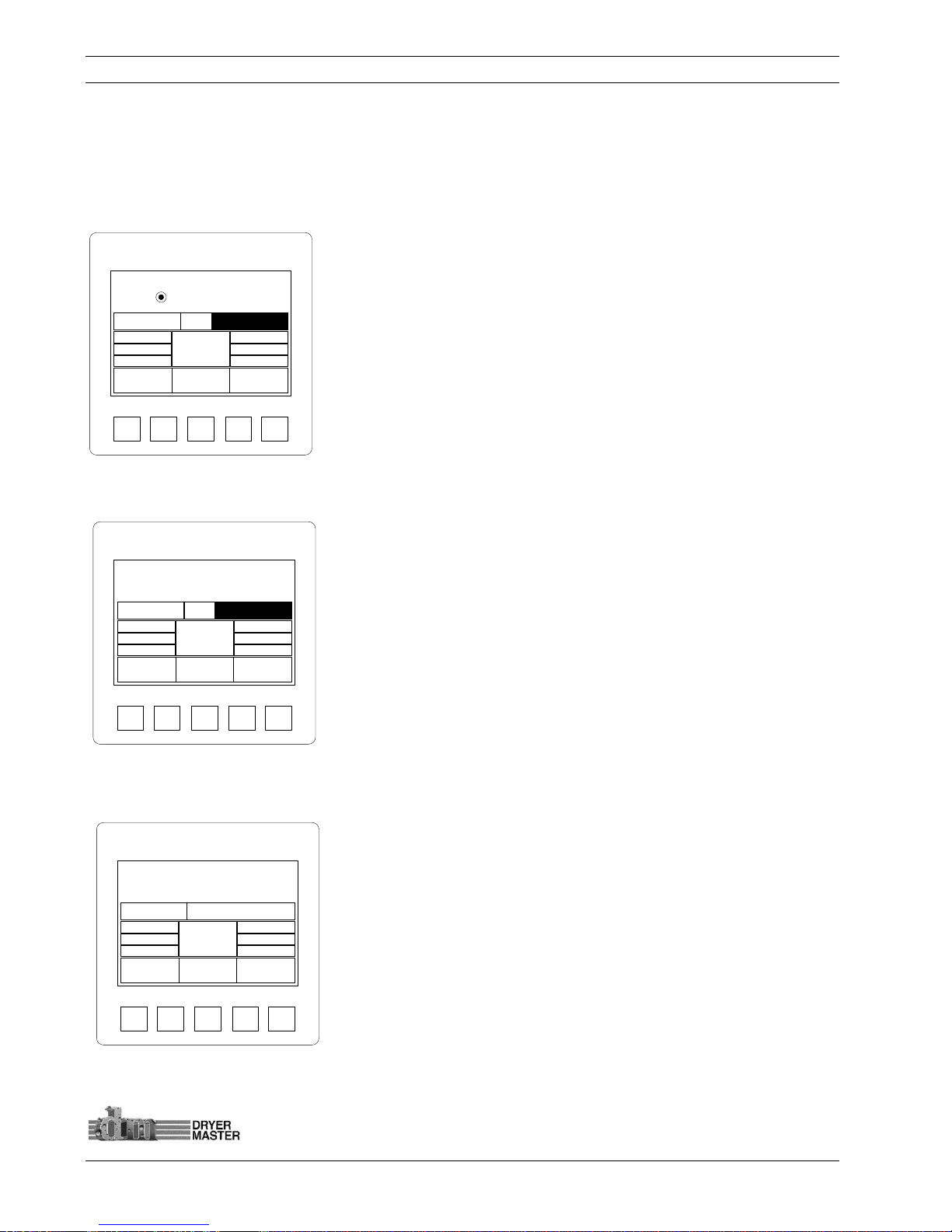
3.4 Main operations displays
3.4.1 Main Display – Local Mode - Sensor Empty
The Main Operations screen displays product moisture, product name, product temperature and the
dryer discharge rate while in Manual or Automatic mode. It is shown here with the Sensor Empty and
the dryer rate set at the dryer.
The Main Operations screen will display “Empty” under the following
conditions
• The moisture sensor is partially or completely empty
• The product is flowing too quickly.
• The product moisture is below the sensors reading threshold
• The sensor is not sending a signal
• The sensor is not connected
Figure
11.
–Main Display – Sensor Empty,
3.4.2 Main Display – Local Mode
Note the Moisture is displayed as well as the product name.
The system is in “Local” mode; dryer discharge rate is set at the dryer
thus there is no rate display.
Press the “Touch Area” <Rate :> or the text <See Dryer> to
display the rate entry screen and set a rate value prior to
switching modes.
Figure
12.
–Main Display – Local Mode
3.4.3 Main Display – Manual Mode
The system is in “Manual” mode; dryer discharge rate is set here at
the display.
Press the “Touch Area” <Rate :> or the rate value <10.00> to display
the rate entry screen.
Figure
13.
–Main Display – Manual Mode
SYSTEM
F1 F2 F3 F4
CORN
15.0%
75 °F
Rate: 10.00
Trend Menu
Auto
Setup
See Dryer
Mode:
Local
16.0%
15.0%
14.0%
55.00
50.00
45.00
SYSTEM
F1 F2 F3 F4
CORN
75 °F
Rate: 10.00
Trend Menu
Auto
Setup
See Dryer
Mode:
Local
16.0%
15.0%
14.0%
55.00
50.00
45.00
Empty
SYSTEM
F1 F2 F3 F4
CORN
15.0%
Mode:
Manual
75 °F Rate: 10.00
Trend Menu
Auto
Setup
16.0%
15.0%
14.0%
55.00
50.00
45.00
Dryer Master AM3 Product Manual
©Dryer Master Inc. Page: 16
3.4.4 Main Display – Automatic Mode
The system is in “Automatic” mode; dryer discharge rate is set here at the display. Depending on the
product moisture the system will switch between the 3 rates displayed. The rate values can be set by
pressing the Rate values touch area or in the “Auto setup” section. The Main rate will continue to need
periodic manual adjustment to maintain the operating window.
Press the “Touch Area” <Rate :> or the rate value <50.00> to display
the rate entry screen.
Press the “Touch Area” <Rate Values> to display the rate entry
screen.
Press the “Touch Area” <Moisture targets> to display the moisture
target and moisture trigger point entry screen.
Figure
14.
–Main Display – Automatic Mode
3.4.5 Alarm screen
The Alarm screen will display when the displayed moisture or
product temperature is in alarm. The active alarms will flash.
Press the “Touch area” <Exit> to return to the main screen
Press the “Touch area” <Alarm Log> to view the alarm history. See
section “Alarm settings” for additional information.
Figure
15.
–Alarm screen
3.4.6 Main Display – Active Alarm
The Main Operations screen with active Alarm
The product label is replaced with an alarm event indicator. The
alarm Indicator will stay active until the condition clears
See section “Alarm settings” for information on setting the alarm
limits.
Figure
16.
–Main Display – Active Alarm
SYSTEM
F1
Exit
Cr i t . Lo w Temp.
F2 F3 F4
Active Alarms
War n. Lo w Temp.
Cr i t . Lo w Moi s t .
War n. Lo w Moi s t .
Alarm
Log
SYSTEM
F1 F2 F3 F4
CORN
15.1%
Mode:
Automatic
75 °F Rate: 50.00
Trend Menu
Auto
Setup
16.0%
15.0%
14.0%
55.00
50.00
45.00
SYSTEM
F1 F2 F3 F4
ALARM
5.1%
Mode:
Automatic
75 °F Rate: 50.00
Trend Menu
Auto
Setup
16.0%
15.0%
14.0%
55.00
50.00
45.00

Dryer Master AM3 Product Manual
©Dryer Master Inc. Page: 17
3.5 Moisture trend displays
One (1) hour or two (2) hour moisture trends in 3 moisture ranges are available for display, 0-10%, 10%20% and 20%-40%.. Trending must be enabled and configured before this function becomes active.
See the section on Trending Options to enable and configure moisture trending.
Note trending is an integrated function of the displays firmware. The information and display scaling is
limited.
3.5.1 One Hour Moisture trend display
One (1) hour moisture trend
Press the “Touch area” <Exit> to return to the main screen
Figure
17.
–One (1) hour Moisture Trend
3.5.2 Two Hour Moisture trend display
Two (2) hour moisture trend
Press the “Touch area” <Exit> to return to the main screen
Figure
18.
–Two (2) hour Moisture Trend
SYSTEM
F1 F2 F3 F4
%
Time (10min/DIV)
Exit
2
0
1
0
SYSTEM
F1 F2 F3 F4
Exit
%
Time (20min/DIV)
2
0
1
0
Dryer Master AM3 Product Manual
©Dryer Master Inc. Page: 18
4 Operating the Dryer from the AM3
This section will describe how to operate the dryer from the AM3. The modes of operation are
reviewed as well as an in-depth description of the 3 modes of Automatic. This section assumes the AM3
has already been calibrated and set up to work with your dryer. Refer to the section “The Menu Tree”
to set up the various alarm settings and especially the rate output setup in the engineering section.
4.1 Operating the System
At start-up the system will boot to this current operation or main screen. While in manual mode the
rate set point will display whether the dryer is running or not.
4.1.1 Main Display – Local Mode
With the dryer running and discharging product you will see a moisture reading, the product
temperature, and the rate is displayed if in “Manual” or Automatic” mode. There is no feed back so we
do not know what the rate is in “Local” mode.
Press the “Touch area” <Mode: > to display the Mode change screen.
Press the “Touch area” <Rate: > to display dryer discharge speed
“Rate” entry screen.
Press the “Touch area” <Auto Setup> to adjust or modify the
Automatic operation settings.
Figure
19.
–Main Display
4.1.2 Operating Mode Select Screen
Press the “Touch area” Up or down arrow to toggle between
the modes “Local”, “Manual”, and “Automatic”
Press the “Touch area” <Enter> to select the item and return to the
main screen.
Press the “Touch area” <Esc > to return to the Main screen.
Figure
20.
–Mode Select screen
Local
SYSTEM
F1 F2 F3 F4
Enter
Esc
Local
SYSTEM
F1 F2 F3 F4
CORN
15.0%
75 °F
Rate: 10.00
Trend Menu
Auto
Setup
See Dryer
Mode:
Local
16.0%
15.0%
14.0%
55.00
50.00
45.00

Dryer Master AM3 Product Manual
©Dryer Master Inc. Page: 19
4.1.3 Setting Drying Rate
Press the “Touch area” Keypad to type a dryer discharge rate.
Press the “Touch area” <Enter> to select the item and return to the
main screen.
Press the “Touch area” <Esc > to return to the Main screen.
Figure
21.
–Drying rate setting screen
How setting the Rate works:
There are 3 modes of operation:
1. “Local” – Speed is set at the dryers speed potentiometer or keypad. This is manual mode
and the operator will need to decide what speed needs to be selected. The Moisture and
product temperature display is available so even this manual mode is enhanced with
continuous moisture information.
2. “Manual” – The speed is set from the Dryer Master AM3. This is also a manual mode and the
operator still needs to decide what speed needs to be selected. The advantage is the speed is
now set digitally from the AM3 panel. Speeds are recorded and printed if the printer and
compact flash option where ordered as part of the system.
3. “Automatic” – The normal or primary speed is also set from the Dryer Master AM3. This is a
semi automatic mode. The operator adjusts the speed so that the target moisture is achieved.
The system will then switch between normal running or primary speed and the high speed set
point or the low speed set point. Depending on the product moisture and trigger targets.
Periodic adjustment of the normal speed is required if the system deviates from target
significantly.
37.00
_QZ
1
GHI
4
PRS7TUV8WXY
9
.
SYSTEM
F1 F2 F3 F4
0+/-
ABC2DEF
3
JKL5MNO
6
Enter
Esc

Dryer Master AM3 Product Manual
©Dryer Master Inc. Page: 20
4.2 Auto Setup
There are various features available in Automatic mode. These should be reviewed and set up to best
reflect your operation and needs. The setup can be changed at any time should the need arise.
4.2.1 Auto Setup – Setting Speed Limits and Delay time
Press the “Touch area” <Max safe Speed> to display the numeric
touch pad data entry screen for setting the maximum speed.
Press the “Touch area” <Min safe Speed> to display the numeric
touch pad data entry screen for setting the minimum speed.
Press the “Touch area” <Hi/low delay Time> to display the numeric
touch pad data entry screen to set the delay before changing the
speed. Time is in seconds.
Press the “Touch area” <Norm Spd. delay Time> to display the
numeric touch pad data entry screen to set the delay before changing
the speed back to normal speed. Time is in seconds.
Press the “Touch area” <Exit > to return to the Main screen.
Press the “Touch area” <Next > to continue to the next menu screen.
Figure
22.
– Auto Setup – Speed limits and delay time
How the speed limits and delay time work:
The Speed limits and delay times serve as constraints to ensure safe and reliable operation. These
should be set with care and possibly experimentation to ensure optimum performance
1) Max Safe Speed – This is the maximum speed your drying system can operate at. Before
setting this speed consider the takeaway and feed systems to ensure this setting will not
overload the equipment. Also look at the real operation. If you know your dryer should never
operate above 70 for any reason this should be set to 70 or possibly less.
2) Min Safe Speed – This is the minimum speed your drying system can operate. Same as before
there is a minimum speed below which the system should never need to operate.
3) Hi /Low Delay Time – This is the time in seconds the moisture has to be either above the “high
limit moisture target” or below the “low limit moisture target” before the speed will change to
either the “low speed setpoint” or the “high speed setpoint”. Time is in seconds, 300 seconds is
5 minutes. 999 seconds or about 16 minutes 39 seconds is the maximum delay available.
4) Norm Spd Delay Time – (Normal Speed Delay Time) This is the time in seconds the moisture has
to have returned to normal (the window between the “high and low moisture target”) or have
moved to the other side of the target moisture ( mode dependent) before the speed is again
returned to normal mode. 999 seconds or about 16 minutes 39 seconds is the maximum delay
available.
SYSTEM
F1 F2 F3 F4
Exit Next
Max Safe Speed 100.00
Min Safe Speed 10.00
Hi / Low Delay Time 300s
Norm Spd Delay Time 300s

Dryer Master AM3 Product Manual
©Dryer Master Inc. Page: 21
4.2.2 Auto Setup –Limits and Rate Mode selection
Press the “Touch area” <Moist. And Rate Limits> to display the
moisture target, moisture limits and Rate Settings selection menu
screen
Press the “Touch area” <Mode A, Mode B, or Mode C> to select
the Automatic operating mode.
Press the “Touch area” <Exit > to return to the Main screen.
Press the “Touch area” <Back > to return to the previous menu
screen.
Figure
23.
– Auto Setup – Limits and Rate mode selection
How Control works:
There are 3 Automatic modes: This is a state machine. Control is achieved by triggering 1 of 3 speed
set points using target moisture, moisture limits and delay times. All these items are user settable and
may require periodic adjustment for optimum performance. The operator decides which mode bests
suits the operation. Automatic modes can de changed at any time.
1) Mode A – This mode requires input from the operator for all 3 speed settings. The normal
running speed as well as the high and low default speeds need to be set. If the normal speed
is adjusted the high and low speed settings must also be reviewed and adjusted if need be.
2) Mode B – This mode once set up requires input from the operator with occasional adjustments
of the normal or primary running speed. The high speed set point and low speed set point
track the normal or primary speed to maintain a constant operating window.
3) Mode C – This mode once set up also only requires input from the operator with occasional
adjustments of the normal or primary running speed. The high speed set point and low speed
set point track the normal or primary speed to maintain a operating window as a percentage of
the primary speed.
SYSTEM
F1 F2 F3 F4
Exit Help
Moist. And Rate Limits
Rate Mode Select
Mode A
Back
Mode B Mode C

Dryer Master AM3 Product Manual
©Dryer Master Inc. Page: 22
4.2.3 Auto Setup – Moisture Targets, Moisture Limits and Rate Settings selection
Press the “Touch area” <Target Moisture > to set the moisture
target
Press the “Touch area” <High Moist Limit> to set the High
Moisture trigger point for Automatic operating mode.
Press the “Touch area” <Low Moist Limit> to set the Low
Moisture trigger point for Automatic operating mode.
Press the “Touch area” <Rate Setup> to continue to the rate
setup screen.
Press the “Touch area” <Exit > to return to the Main screen.
Press the “Touch area” <Back > to return to the previous menu
screen.
Figure
24.
– Auto Setup – Moisture targets, Moisture Limits and Rate settings selection
How to set up Control:
This section will explain what happens.
In all Automatic modes it is prudent for the operator to operate the dryer manually to attain the
desired moisture, before selecting Automatic. It is important to monitor the operation and adjust the
settings to permit the dryer and Dryer Master AM3 to operate effectively.
SYSTEM
F1 F2 F3 F4
Exit
Target Moisture 15.0%
High Moist. Limit 16.0%
Low Moist. Limit 14.0%
Rate Settings
Back

Dryer Master AM3 Product Manual
©Dryer Master Inc. Page: 23
4.2.4 Auto Setup –Rate Selection Mode A
Press the “Touch area” <Normal Rate > to display the numeric
touch pad data entry screen for setting the “Normal” running
speed.
Press the “Touch area” <High Rate > to display the numeric
touch pad data entry screen for setting the High Rate speed. This
is the speed the system will run will moisture is below the “Low
Moist. Limit”
Press the “Touch area” <Low Rate > to display the numeric
touch pad data entry screen for setting the Low Rate speed. This
is the speed the system will run will moisture is above the “High
Moist. Limit”
Figure
25.
– Auto Setup –Rate selection Mode A
Press the “Touch area” <Exit > to return to the Main screen.
Press the “Touch area” <Back > to return to the previous menu
screen.
1) Mode A:
a. An event happens and the moisture drifts away from target.
b. The moisture goes high. The moisture goes above the High limit target occasionally but
nothing happens. Note, there is a timer that is triggered anytime the moisture goes
above the high limit target or low limit target.
c. Once the moisture stays above the High limit target for the programmed length of time
(default is 300 seconds = 5 minutes). The low speed setting is activated.
d. The system will now operate at this slower speed setting until the moisture is once
again below the High limit target.
e. When the moisture has been below the High moisture target for the programmed
length of time (default is 300 seconds = 5 minutes) system will return to the normal or
primary speed.
f. A second event happens and the moisture again drifts away from target
g. This time the moisture goes dry. The moisture goes below the Low limit target. Again
the moisture has to stay below the Low limit target for the programmed length of time
(default is the same 300 seconds = 5 minutes)
h. Once the moisture stays below the Low Limit target for the programmed length of time
(default is 300 seconds = 5 minutes). The high speed setting is activated.
i. The system will now operate at this higher speed setting until the moisture is once
again above the Low limit target.
j. When the moisture has been above the Low moisture target for the programmed
length of time (default is 300 seconds = 5 minutes) system will return to the normal or
primary speed.
The system will cycle between the speed settings triggered by the moisture target and limits. In
Mode A all 3 speeds are manually set, as well as the moisture target and limits, and the delay time.
SYSTEM
F1 F2 F3 F4
Exit
High Rate 55.00
Normal Rate 50.00
Low Rate 45.00
Back

Dryer Master AM3 Product Manual
©Dryer Master Inc. Page: 24
4.2.5 Auto Setup –Rate Selection Mode B
Press the “Touch area” <Normal Rate > to display the numeric
touch pad data entry screen for setting the “Normal” running
speed.
Press the “Touch area” <H / L Rate > to display the numeric touch
pad data entry screen for setting the “High Rate speed”. This the
difference value from the “Normal Rate”.
In this example, “Normal rate” + “H/L rate” = “High Rate”, 50 + 5 =
55 and “Normal rate” - “H/L rate” = “Low Rate”, 50 - 5 = 45
Press the “Touch area” <Exit > to return to the Main screen.
Press the “Touch area” <Back > to return to the previous menu
screen.
Figure
26.
– Auto Setup –Rate selection Mode B
2) Mode B:
a. Events are identical to Mode A. An event happens and the moisture drifts away from
target.
b. The moisture goes high. The moisture goes above the High limit target.
c. Once the moisture stays above the High limit target for the programmed length of time
(default is 300 seconds = 5 minutes). The low speed setting is activated.
d. The system will now operate at this slower speed setting until the moisture is once
again below the High limit target.
e. Only in Mode B the slower as well as the higher speed settings are a fixed value change,
an offset from the normal or primary speed. This is a parameter settable by the user.
f. If an adjustment is require to the normal or primary operating speed the High and Low
speed settings will also change by the programmed offset.
The system will cycle between the speed settings triggered by the moisture target and limits. In
Mode B the normal or primary speed is manually set, as well as the moisture target and limits, and
the delay time and possibly an occasional tweak of the speed offset.
SYSTEM
F1 F2 F3 F4
Exit
Normal Rate 50.00
H / L Rate Change 5.00
Back

Dryer Master AM3 Product Manual
©Dryer Master Inc. Page: 25
4.2.6 Auto Setup –Rate Selection Mode C
Press the “Touch area” <Normal Rate > to display the numeric
touch pad data entry screen for setting the “Normal” running
speed.
Press the “Touch area” <% Rate Change> to display the numeric
touch pad data entry screen for setting the % Rate Change. This
the difference value from the “Normal Rate” as a percent of the
normal rate.
In this example, “Normal rate” + “% Rate Change” = “High Rate”, 50
+ (50/100*10) = 55 and “Normal rate” - “% Rate Change” = “Low
Rate”, 50 – (50/100*10) = 45
Press the “Touch area” <Exit > to return to the Main screen.
Figure
27.
– Auto Setup –Rate selection Mode C
Press the “Touch area” <Back > to return to the previous menu
screen.
3) Mode C:
a. Events are identical to Mode A. and B
b. If an adjustment is require to the normal or primary operating speed the High and Low
speed settings will also change by the programmed offset. In this case this offset is
dynamic because it is a percentage of the normal or primary running speed. Therefore
the amount of change will be smaller at lower speeds and larger for higher speeds thus
reducing the input required by the user.
The system will cycle between the speed settings triggered by the moisture target and limits. In
Mode C the normal or primary speed is manually set, as well as the moisture target and limits, and
the delay time and possibly a tweak of the speed offset percentage.
4) All modes will require some tuning to optimize the system operation. Different dryers and
different products will require slightly different operating parameters. The default parameters
should allow the system to operate and provide good results. Adjusting the moisture targets
and limits and finding the optimum speed offsets for your application should allow the system
to maintain very good moisture control.
5) The key is to maintain the normal running rate settings where it needs to be and provide a
sufficient window with the high and low rate change settings to allow the system to operate
effectively.
SYSTEM
F1 F2 F3 F4
Exit
Normal Rate 50.00
% Rate Change 10.0%
Back

Dryer Master AM3 Product Manual
©Dryer Master Inc. Page: 26
5 The Menu Tree
This section describes the various menus and screens and details functions, such as changing product,
adjusting the moisture sensor calibration, setting alarms, reviewing the alarm log and others are all
available by pressing the “Touch area” <Menu>. Each item will be covered in detail in the following
pages. We have attempted to place the more used functions to the front and the progressively less
used items to the rear.
5.1 Main Menus
5.1.1 Menu – Screen 1
Press the “Touch area” <F1 Change Product> or the <F1> button to enter
the Product selection screen.
Press the “Touch area” <F2 Calibrate Sensor> or the <F2> button to enter
the Sensor Calibration adjustment screen.
Press the “Touch area” <F3 Set Alarms> or the <F3> button to enter the
Product moisture and Product Temperature Alarms adjustment screen.
Press the “Touch area” <F4 Alarm log> or the <F4> button to review a
recent history of alarm occurrences.
Press the “Touch area” <Exit> to return to the main screen
Press the “Touch area” <Next > to move to the next screen
Figure
28.
–Menu One (1)
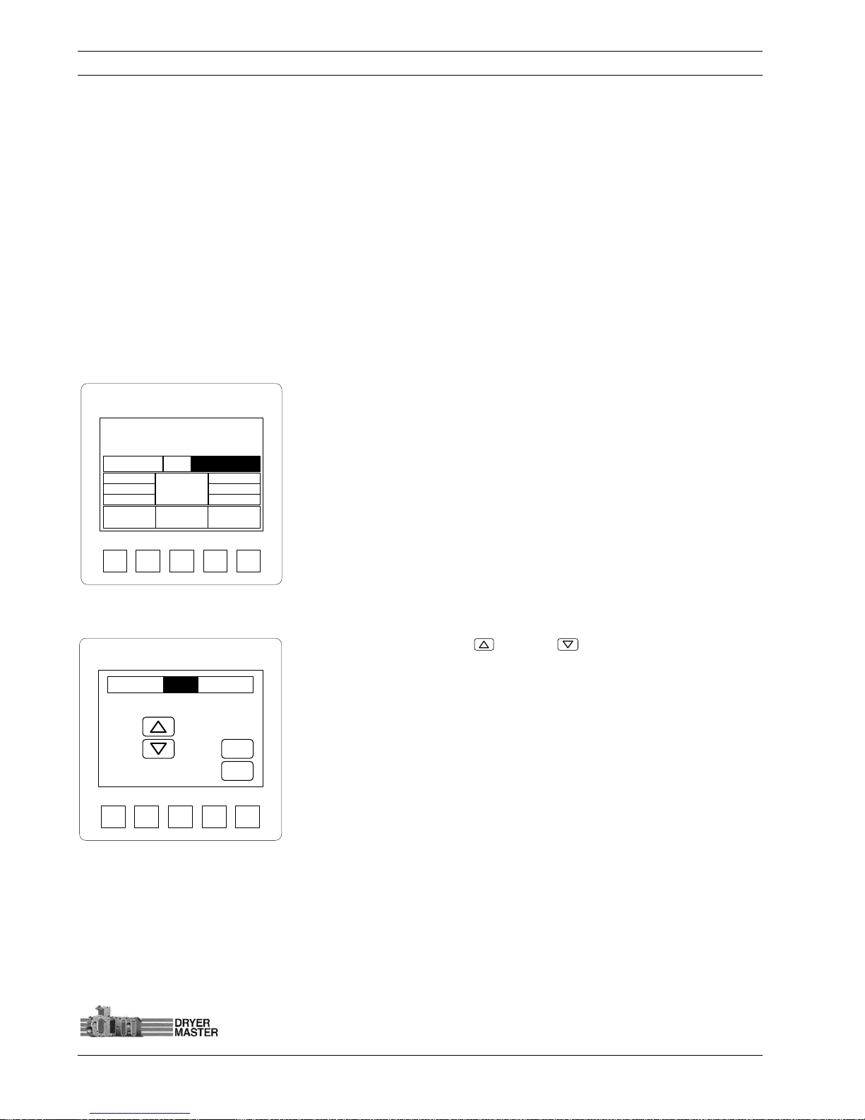
5.1.2 Menu – Screen 2
Press the “Touch area” <F1 Alarm Delay> or the <F1> button to enter the
Local alarm activation delay screen.
Press the “Touch area” <F2 Remote Alarm Delay> or the <F2> button to
enter the Remote alarm activation delay screen.
Press the “Touch area” <F3 Printing > or the <F3> button to enter the
Printing setup and enable screen.
Press the “Touch area” <F4 Temp. Scale> or the <F4> button to enter the
screen to switch the temperature display from degrees Fahrenheit to
degrees Celsius
Press the “Touch area” <Exit> to return to the main screen
Press the “Touch area” <Back> to return to the previous screen
Press the “Touch area” <Next > to move to the next screen
Figure
29.
–Menu Two (2)
5.1.3 Menu – Screen 3
Press the “Touch area” <F1 System Settings> or the <F1> button set
various device related items. Date & time, contrast and the screen saver
Press the “Touch area” <F2 Eng. Functions> or the <F2> button to enter
the Engineering setup screens. Password protected. ___________________
Press the “Touch area” <F3 Languages > or the <F3> button to change the
displayed language.
Press the “Touch area” <F4 Trending Options> or the <F4> button to enter
the screen to Trending moisture scaling and time.
Press the “Touch area” <Exit> to return to the main screen
Press the “Touch area” <Back> to return to the previous screen
Press the “Touch area” <Next > to move to the next screen
Figure
30.
–Menu Three (3)
SYSTEM
F1 F2 F3 F4
Exit Next
F1 Change Product
F2 Calibrate Sensor
F3 Set Alarms
F4 Alarm Log
SYSTEM
F1 F2 F3 F4
Exit Next
F1 Alarm Delay
F2 Remote Alarm Delay
F3 Printing
F4 Temp. Scale
Back
SYSTEM
F1 F2 F3 F4
Exit Next
F1 System Settings
F2 Eng. Functions
F3 Languages
F4 Trending Options
Back
 Loading...