

Page 1
Page 2

Furnace Humidifier
2
FREQUENTLY ASKED QUESTIONS
Question:
Answer: The unit will work on most forced air furnaces
incorporating a heating source, a supply duct, and a return duct
at least 8” in width.
Comment: The technology used in this humidifier to deliver
moisture to the air is the simplest and easiest style, a bypass type
evaporative humidifier. Your furnace fan creates a pressure difference
between the supply air (hot, high pressure) and return air (cold, low
pressure). By installing a bypass tube between the supply and return
duct a small amount of air is forced (via the pressure difference) to
flow from the supply duct through the humidifier’s evaporator pad
and back into the return duct. What will differ from furnace to
furnace or home to home is how much moisture or capacity you will
get from the unit. There are several factors which will affect this, how
old is your home, how old is your furnace, how well insulated is your
home. For example, the capacity for this unit is 15 US gallons per 24
hrs of operation. This is based on ARI standards (120’F hot air temp,
60’F water supply temp, 0.5” static pressure difference between
supply & return duct), used by all humidifier manufacturers. If your
furnace is a hi efficiency or pulse type furnace the hot air
temperature may be less, or the length of time the furnace burner is
on may be less; therefore as a rule of thumb we would say you
would get approx. 75% to 80% of rated output.
Question: How much moisture does the humidifier deliver to
the air in my home?
Answer: This model will deliver 15 US Gallons (12.5 Imperial
gallons, 57 litres) per 24 hours of operation.
Comment: 24 hours of operation means at design conditions; your
furnace will only deliver the required hot air (120’F) when it is on.
Your furnace should not cycle more than 1/3 of the time so the 24
hours of humidifier operation may take up to 3 days to complete.
Question: How much water does this humidifier use?
Answer: This humidifier is 100% efficient, meaning all the water it
uses is delivered to the air to humidifier your home. It will use 15
US gallons (12.5 Imperial gallons, 57 litres) per 24 hrs of operation.
Comment: As mentioned above 24 hours of operation means at
design conditions – your furnace will only deliver the required
hot air (120’F) when it is on. Your furnace should not cycle more
than 1/3 of the time so the 24 hours of humidifier operation may
take up to 3 days to complete.
Question: I’m replacing an old humidifier on my furnace
can I use the old components?
Answer: You should replace all the components to ensure good
operation. You may be able to utilize the existing duct cut outs for
the new install however some reworking may be required.
Comment: As a rule we like to see you change all the
components, particularly the water supply tube. As over time
minerals, solids, or sludge may have built up, these will very
quickly clog the water inlets, or over time the tube may have
become worn or leaky. Replace the bypass duct as well, there
may be secondary dampers unseen which will block air or again
What type of furnaces will this humidifier work on?
there may be unseen wear. The same goes for electrical
components or wiring these may be malfunctioning or worn out.
Note: If you have a humidifier which was interlocked with your
furnace (meaning the humidifier only came on when the furnace
came on) then the old transformer is wired in with your furnace.
Do not attempt to disconnect this transformer from the furnace
only disconnect the low voltage side wires for the humidifier and
tape over the terminals.
Question: I’ve installed the humidifier on my furnace and it
is functioning properly but I do not feel anything and
humidistat reading is not changing, is the humidifier working?
Answer: As long as there is hot air going through the humidifier
and there is water pan and the drum assembly is getting wet then
moisture is being delivered to the air in your home.
Comment: All year, and especially during the winter months
when many combustion appliance are operating in your home,
fresh outdoor air is required to ensure a healthy environment for
your family. Do not think of your home as a sealed bubble, no
matter how well insulated, all homes breath (some more than
others). The cold dry outside air is mixing with the air in your
home constantly, even when your furnace is not running. A
furnace humidifier will work to offset the constant effect the dry
outside air has on your home, and your home’s furnishings.
Throughout the winter there is a constant diminishing and
replenishing of moisture levels in the home, conditions inside and
out rarely remain stagnant for any length of time.
Installation
• READ THESE INSTRUCTIONS FULLY BEFORE INSTALLING
THIS PRODUCT.
• SAVE THESE INSTRUCTIONS FOR REFERENCE.
• SHUT THE WATER OFF BEFORE WORKING ON THE HUMIDIFIER.
• SHUT THE POWER OFF BEFORE WORKING ON THE
HUMIDIFIER.
• TAKE PRECAUTION WHEN CUTTING OR HANDING METAL
PCS. (CUT DUCT WORK), SHARP EDGES CAN CAUSE
SERIOUS INJURY.
• WHEN DRILLING OR CUTTING INTO DUCTING BE
EXTREMELY CAREFUL NOT TO DAMAGE AIRCONDITIONING COILS OR OTHER FURNACE APPARATUS.
• THIS UNIT MUST BE INSTALLED IN 8” WIDE DUCT
MINIMUM.
• DO NOT INSTALL THIS UNIT WHERE EXTREME TEMPERATURES
EXIST (BELOW 8˚C / 45˚F OR ABOVE 63˚C / 145˚F).
• THIS UNIT IS NOT SUPPLIED WITH A DRAIN TUBE.
HOWEVER WE DO RECOMMEND YOU PURCHASE AND
INSTALL A
INSTRUCTIONS) TO PROTECT AGAINST WATER
OVERFLOW.
• FOR THIS UNIT TO OPERATE PROPERLY IT MUST BE
INSTALLED ON A FORCED AIR HEATING SYSTEM WITH A
SUPPLY DUCT AND RETURN DUCT.
• THE HUMIDIFIER AND THE BYPASS COLLAR DAMPER ARE
TO BE INSTALLED ON DUCTING ONLY. UNDER NO
CIRCUMSTANCES MOUNT ANY COMPONENT TO THE
FURNACE BODY.
1
/2” DRAIN TUBE (SEE SECTION INSTALLATION
Page 3
Furnace Humidifier
INSTALLATION AND OPERATING INSTRUCTIONS:
Furnace Humidifier
3
• ELECTRICAL WIRING, WATER SUPPLY, AND DRAIN TUBE
MUST NOT KINK OR COME INTO CONTACT WITH SHARP
EDGES OR HOT SURFACES.
• IF REPLACING AN EXISTING FURNACE HUMIDIFIER, WE
RECOMMEND YOU REPLACE ALL COMPONENTS TO
ENSURE PROPER HUMIDIFIER OPERATION.
• THE INSTALLATION OF THIS PRODUCT MUST COMPLY
WITH NATIONAL AND LOCAL ELECTRICAL, PLUMBING,
BUILDING, AND MECHANICAL CODES.
REQUIRED TOOLS
• Safety glasses
•Workgloves
• Electric or cordless drill
3
• Drill bits (
• Tin snips
• Full size Philips or Roberstons screw driver
• Short handle Philips or Roberstons screw driver
• Adjustable wrench
• Utility knife
• Pliers
• Level
• Tape
• Measuring tape or ruler
• Medium-grit sand paper
• Pencil
/8",1/8",7/32”,7/64")
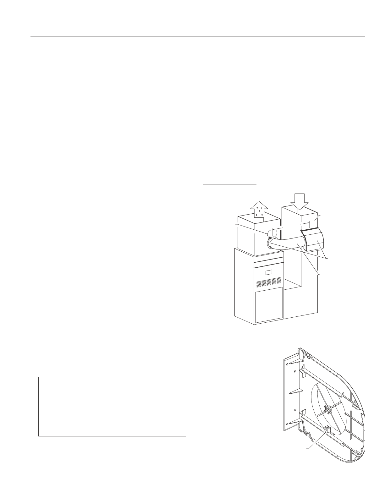
no more than 30” to ensure maximum air flow through the
humidifier.
3. The supplied flex bypass tube is cut to the proper length and
pulled tight to ensure maximum air flow.
4. The humidistat is located a minimum of 6” upstream of the
humidifier, where moist air will enter the return duct.
5. The bypass damper is fully open.
6. The humidifier is mounted level on the duct.
7. There is nothing inside the duct behind the bypass collar and
damper or the humidifier body.
8. The humidifier body and the bypass collar and damper are level.
IDEAL INSTALLATION
Figure 1
Damper fully open
SUPPLY DUCT
HOT AIR
RETURN DUCT
COLD AIR
No more
than 30"
8" wide duct minimum
Bypass collar and
unit level
Bypass tube pulled
tight and cut to length
SELECTION OF LOCATION
TO MOUNT THE HUMIDIFIER
All bypass type furnace-mount humidifiers rely on the pressure
difference which exists between the supply duct (hot air) and the
return duct (cold air) to create an air flow through the
humidifier’s evaporator pad. The air will ALWAYS flow from hot
(high pressure) to cold (low pressure).
•INSTALLATION TIP: Before starting fully plan out the
installation. Check for the locations of the humidifier,
bypass collar & damper, and the humidistat and
associated sensors. Plan the length and type of ducting
required, the water supply, the water drain, the electrical
wiring, and a constant 120 volt outlet to plug in the
transformer. This will ensure your installation goes as
easy and quickly as possible
1. The humidifier body and bypass tube are installed at eye level,
easily accessible for installation and routine maintenance.
2. The space between the humidifier body and bypass tube are
Not all installations will be as shown above – in cases where:
• The bypass duct
required is more than
the supplied 30”
• The bypass collar and
damper must be
installed above or
below the humidifier
• The bypass collar and
damper must be
installed
perpendicular to the
humidifier
Use hard metal duct and
hard metal elbows. This will
minimize the amount of air-
SNAP OFF
AND SAVE
flow restriction.
Figure 2
Page 4
Furnace Humidifier
4
HUMIDIFIER BODY INSTALLATION
This humidifier is designed to be mounted on the return duct
(cold air) for safety reasons. This will minimize the exposure to
high temperatures and extend product/component life. Always
take precaution to ensure that water supply tube, water drain
tube, any electrical wiring does not become kinked or come into
contact with sharp edges or hot surfaces. Keep in mind that the
humidistat must be mounted at least 6” upstream from the
humidifier cabinet, where moist air enters the duct.
CAUTION: When cutting or drilling into ducting take care not to
damage any air-conditioning coils or other furnace apparatus.
CAUTION: Wear safety glasses and work gloves when installing
this unit, sharp metal edges can cause severe injury.
CAUTION: Turn the furnace off before starting this installation.
This humidifier cabinet consists of two side panels (bypass side
panel and motor side panel), a front cover, and a water pan. The
surface of the duct will form the rear of the humidifier cabinet.
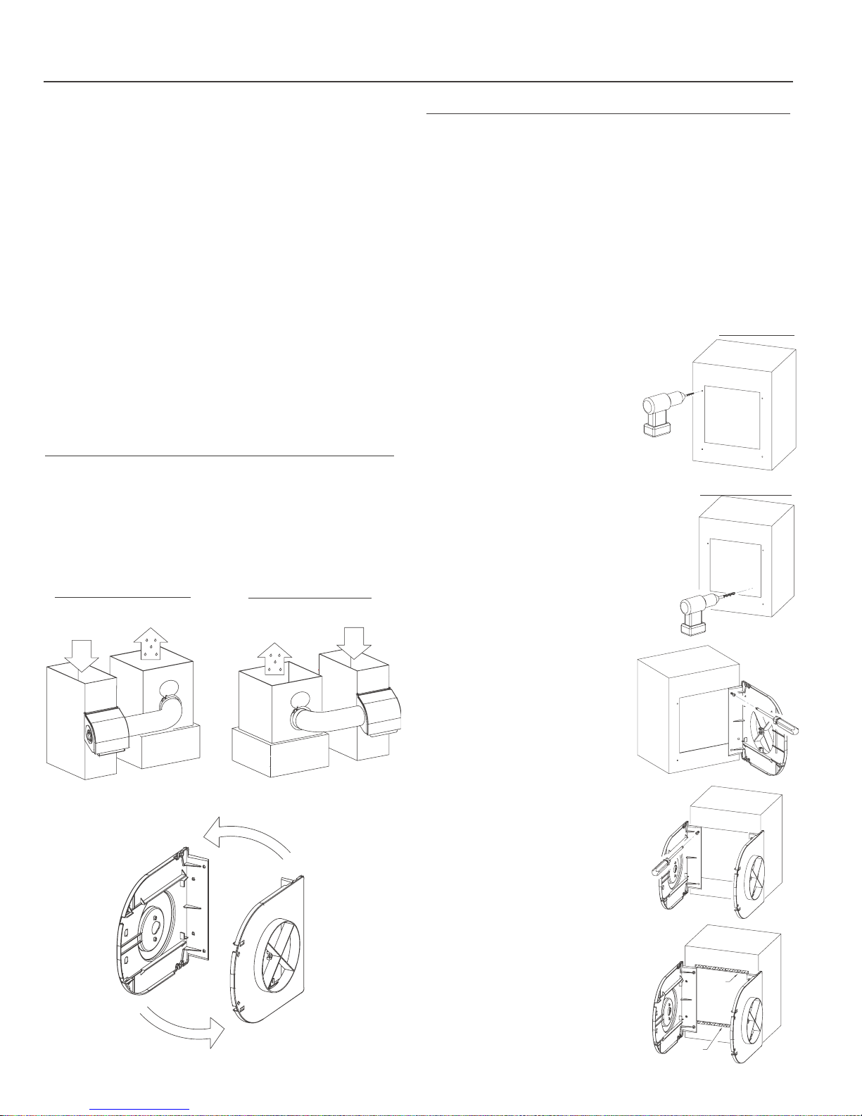
STEP #1: RIGHT HAND DUCTING OR LEFT HAND DUCTING
Once you have decided the best location for the humidifier
determine if the unit must be left or right hand ducting. This will
depend on whether the hot air duct is to the left or right of the
cold air duct. (Fig. 3) The side panels are symmetrical so setting
up for left or right hand ducting is done by flipping the panel 180
degrees. (Fig. 4)
RIGHTHAND DUCTING
SUPPLY DUCT
RETURN DUCT
COLD AIR
HOT AIR
LEFTHAND DUCTING
RETURN DUCT
SUPPLY DUCT
HOT AIR
COLD AIR
STEP #2: MOUNTING THE HUMIDIFIER CABINET ON THE DUCT
If you have not already done so, remove the humidifier side
panels from the carton. Locate the “Humidifier Cabinet
Mounting Template”.
CAUTION: When cutting or drilling into ducting take care not to
damage any air-conditioning coils or other furnace apparatus.
CAUTION: Wear safety glasses and work gloves when installing
this unit. Sharp metal edges can cause severe injury.
CAUTION: Turn off the furnace before beginning this installation.
DRILLING THE HOLES AND MAKING THE CUTOUT
1. Use adhesive tape to affix the
template onto the duct in the
selected location. Use the level
Figure 5
DRILL HOLES
line on the template to ensure the
humidifier cabinet will be
mounted level.
2. Drill the 4 marked
1
/8” side panel
HUMIDIFIER
CUT-OUT
mounting holes. (Fig. 5)
3
3. Using a
/8” drill bit (not supplied)
drill a hole inside the rectangle
area marked “Humidifier Cut
Out”. (Fig. 6)
Figure 6
DRILL CUT-OUT
4. Using the3/8” hole as a starting
point cut out the Humidifier Cut
Out area marked on the template
using tin snips (not supplied). Cut
HUMIDIFIER
CUT-OUT
on the outside of the lines to
ensure the cabinet will fit.
5. Remove remaining portion of the
template from the duct.
Figure 7
MOUNTING THE BYPASS
SIDE PANEL
Figure 3
Flipped 180˚
Figure 4
Flipped 180˚
6. Mount the bypass side panel to
the duct first. This is the side of
the humidifier closest to the hot
air duct.
7. Use 2 of the supplied screws to
secure the bypass side panel onto
the duct work. The screws will
install through two holes on the
bypass side panel flange into two of
the holes drill in #2. (Fig. 7)
MOUNTING THE MOTOR
SIDE PANEL
8. Repeat the last two steps for the
motor side panel. (Fig. 8)
9. After the side panels are mounted
onto the duct install the two strips
of gasket on the duct in between
the two sides top and bottom, as
shown in figure 9.
Figure 8
Figure 9
BOTTOM
GASKET
Page 5
Furnace Humidifier
5
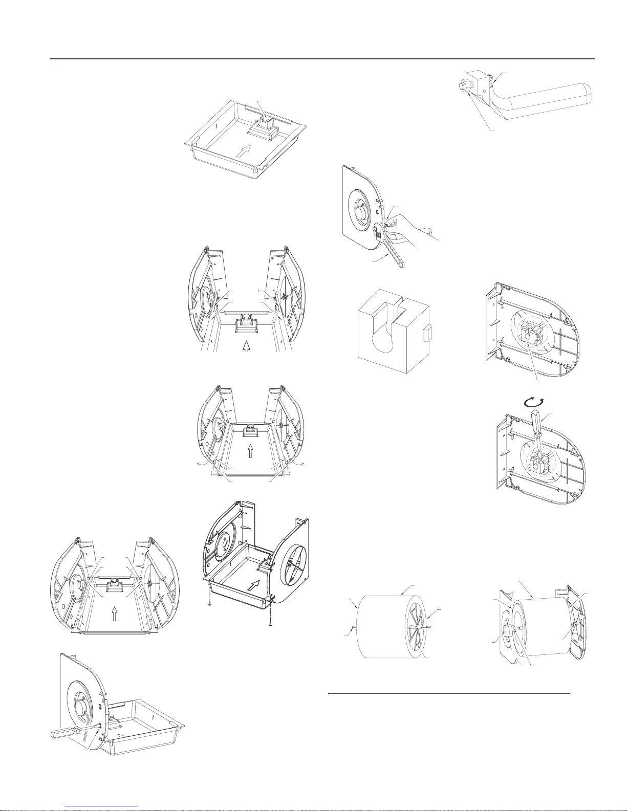
MOUNTING THE WATER PAN
10. Install the water pan into
the side panels. The water
DRAIN FITTING TO
THE REAR OF PAN
pan will install with the
drain fitting to the rear of
the humidifier. (Fig. 10)
IMPORTANT NOTE: IF YOU
ARE PLANNING ON
INSTALLING A DRAIN TUBE
Figure 10
(NOT SUPPLIED) DRILL OUT
THE DRAIN FIT TING AS SHOWN IN THE SECTION “OVERFLOW
DRAIN CONNECTION” BEFORE INSTALLING THE DRUM. ONLY
DRILL OUT THE DRAIN FITTING IF YOU ARE INSTALLING A
DRAIN TUBE. YOU WILL HAVE PURCHASE THE TUBE
SEPARATELY.
11. Position the water pan
between the sides so that
the flange on either side of
the water pan is resting on
ribs on the inside of either
side panel. (Fig. 11)
SIDE
PAN EL R IB
WATER
PAN FLANGE
12. Before the water pan is
fully installed you will have
to slightly deflect the front
of both side panels (one at a
time) to insert the hooks on
the front of the water pan
Figure 12
Figure 11
into slots on the front of the
side panels. (Fig. 12) As you
are doing this be sure that
the rear of the water pan
flange is sliding under the
upper ribs at the rear of the
side panels. (Fig. 13) Once
the water pan is in the
proper position, secure the
water pan in place using the
DEFLECT
SLIGHTLY
SIDE PANEL
SLOT
WATER PAN
HOOK
DEFLECT
SLIGHTLY
two #6 screws provided in
the hardware pack (fig. 13b)
Figure 13
SIDE PANEL
UPPER RIB
PAN FLANGE
IN BETWEEN
SIDE PANEL
LOWER RIB
Figure 13b
INSTALLING THE FLOAT AND
VALVE ASSEMBLY
Figure 14a
Note before installing the float
and valve assembly you will
have to remove the proper
double “D” knockout, refer to
figure 14A. Using a screw driver
remove the lower knockout
closest to the water pan.
KNOCK OUT
THE LOWER DOUBLE D HOLE
13. Once the pan is in place
install the float & valve
assembly, first remove the
white mounting nut (Fig. 14)
FLOAT ASSEMBLY
insert the threaded portion
of the float valve into the
double D hole and secure in
place with the white
mounting nut removed
WHITE MOUNTING NUT
Figure 14
earlier. Hold the valve as straight as possible while tightening
so an accurate water level can be maintained. (Fig. 15)
Figure 15
INSTALLING THE BEARING INTO
THE BYPASS SIDE PANEL
HAND HOLDING
FLOAT STRAIGHT
14. Retrieve the Bearing which
was removed from the bypass side
panel at the beginning of the
installation (Fig. 16) and install it
WRENCH
TIGHTENING
NUT
into the center of the bypass side
panel. (Fig. 17) If replacing or
repairing a bearing insert a slotted
Figure 17
BEARING
Figure 16
BEARING SNAPPED IN
COMPLETELY AND U SHAPE UP
screw driver into the back top of the
bearing and rotate the screw driver,
the bearing will pop out of the side
panel. (Fig. 17B)
Figure 17b
ROTAT E TO
DISLODGE
THE BEARING
INSTALLING THE DRUM AND
EVAPORATOR PAD ASSEMBLY
15. Retrieve the drum and evaporator
pad assembly. This assembly is made
up of the drum the evaporator pad,
and the drum shaft, you will notice
this assembly has an open end and a closed end. (Fig. 18)
16. Starting with the closed end install the drum shaft into the
center of the motor coupling then install the other end of the
drum shaft into the bearing, gently pushing down in place to
position. (Fig. 19)
DRUM EVAPORATOR
PAD ASSEMBLY
BEARING
MOTOR
COUPLING
CLOSED
END
DRUM
SHAFT
Figure 18
EVAPORATOR
PAD
OPEN
END
DRUM
CAGE
CLOSED
END
MOTOR
Figure 19
STEP #3: MOUNTING THE BYPASS COLLAR AND DAMPER
The humidifier comes with a collar & damper mounting
template. If possible ensure the bypass collar will be level to the
humidifier duct connection. Try to keep the bypass collar within
30” of the humidifier. To ensure you have clear access to all
components do not install the flexible bypass tube until all water
and electrical connections are made to the humidifier.
OPEN
END
Page 6
Furnace Humidifier
6
CAUTION: When cutting or drilling into ducting take care not to
damage any air-conditioning coils or other furnace apparatus.
CAUTION: Wear safety glasses and work gloves when installing
this unit. Sharp metal edges can cause severe injury.
1. Use adhesive tape to affix the bypass template onto the duct
in the selected location.
1
2. Drill the 3 marked
3. Using a
3
/8” drill bit (not supplied) drill a hole inside the circular
/8” holes.
area marked collar cut out.
3
4. Using the
/8” hole drilled earlier as a starting point cut out the
Collar Cut Out area marked on the template using tin snips
(not supplied).
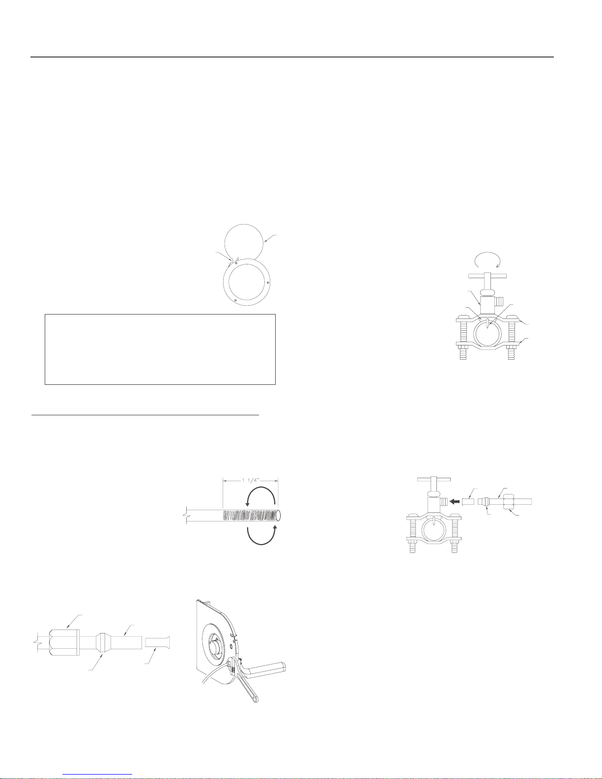
5. Mount the bypass collar and
damper (Fig. 20) using the three
supplied screws. The air damper
should be installed in the open
TOP SCREW
FOR DAMPER
MOUNTING
DAMPER
OPEN
position. The top screw secures the
damper.
Figure 20
•INSTALLATION TIP If replacing an existing humidifier
which has been installed on your furnace you may be
able to use the existing cut-outs, however replace the
components, bypass collar and damper, and bypass
ducting. The majority of furnace humidifiers use 6"
ducting for bypass.
NOTE: The optimum tightness of the nylon compression nut will
leave a gap of approximately
3
/16” between the nylon
compression nut and the nylon hex nut.
INSTALLING THE SADDLE VALVE TO THE WATER PIPE
The water supply for the humidifier is provided from an existing
cold water pipe by using a self-piercing saddle valve. In order for
you to use the supplied plastic tubing, select the nearest cold
water pipe suitable for saddle valve installation.
1. Turn the main water supply off.
2. Rotate the saddle valve handle so that the piercing pin does
not protrude beyond the top clamp.
3. With the rubber gasket in the fixed position, clamp the saddle
valve on the selected location
of the cold water pipe and
mount the bolts and nuts to
the saddle clamps.
4. To pierce the copper pipe,
simply turn valve handle clockwise until you feel that it is
firmly seated. (Fig. 24)
NOTE: Do not open the valve
now. Proceed with the mounting
of the plastic tubing to the saddle
valve first.
SELF
PIERCING
VALVE
RUBBER
GASKET
ROTATE CLOCKWISE
TO PIERCE PIPE
PIERCING PIN
TOP
CLAMP
BOTTOM
CLAMP
Figure 24
CONNECTING THE PLASTIC TUBING TO THE SADDLE VALVE
STEP #4: WATER SUPPLY AND DRAINAGE CONNECTION
WATER CONNECTION TO THE HUMIDIFIER
IMPORTANT: Connect the tubing to the humidifier FIRST before
connecting to the saddle valve.
1. SAND THE END (Fig. 21) of the
plastic water supply tube.
FAILURE TO DO SO MAY RESULT
IN LEAKS. Use medium
sandpaper (not provided) approx
1
/4” from the end in a rotating
1
motion. This assures a non-
Figure 21
slipping, trouble free connection.
2. Slide the nylon compression nut and the black rubber ferrule
onto the sanded plastic tubing and then fit the brass insert into
the end of the plastic tubing. (Fig. 22)
Figure 22
BLACK RUBBER
NYLON COMPRESSION NUT
FERRULE
BRASS INSERT
SANDED TUBE
Figure 23
3. Push the plastic tubing firmly into the humidifier’s
float valve threaded water inlet. Carefully begin
tightening the nut by hand. Use an adjustable wrench to finish
tightening. (Fig. 23)
1. Cut the plastic tubing with a sharp knife to the proper length
to fit between the humidifier and the saddle valve.
2. SAND THE END (Fig. 21) of the plastic water supply tube.
FAILURE TO DO SO MAY RESULT IN LEAKS. Use medium
1
sandpaper (not provided) approx 1
/4” from the end in a
rotating motion. This assures a non-slipping, trouble free
connection.
BRASS
INSERT
SANDED TUBE
3. Slide the brass
compression nut and
nylon ferrule onto the
NYLON
FERRULE
BRASS
NUT
sanded plastic tube
and fit the brass insert
in the end of the
Figure 25
tubing. (Fig. 25)
4. Push the tubing firmly into the saddle valve threaded water
outlet, carefully begin tightening the compression nut by hand
(be careful not to cross the threads). Use and adjustable
wrench to finish tightening the brass compression nut. Do not
over-tighten.
OVERFLOW DRAIN CONNECTION (OPTIONAL)
NOTE: WE STRONGLY RECOMMEND YOU INSTALL A DRAIN
TUBE TO PROTECT YOUR PROPERTY IN CASE OF WATER
LEAKAGE. IF YOU ARE PLANNING ON INSTALLING A DRAIN
TUBE ONTO THE UNIT YOU WILL HAVE TO PURCHASE THE
REQUIRED LENGTH OF TUBING AND A HOSE CLAMP
SEPARATELY. AS WELL YOU SHOULD HAVE DRILLED OUT
THE DRAIN FITTING BEFORE INSTALLING THE WATER PAN
ONTO THE FURNACE. ONLY DRILL OUT THE WATER PAN IF
YOU PLAN TO INSTALL A DRAIN TUBE.
Page 7
Furnace Humidifier
7
REQUIRED SEPARATELY PURCHASED PARTS FOR DRAINAGE
INSTALLATION:
5
/8”OD1/2” ID DRAIN HOSE, LENGTH AS PER YOUR
•
INSTALLATION.
5
• HOSE CLAMP FOR
/8”ODHOSE.
1. Measure the required length of drain tube from the bottom of
the humidifier to an appropriate floor drain.
2. Prepare the drain fitting at the rear of the water pan before
installing the water pan onto the furnace.
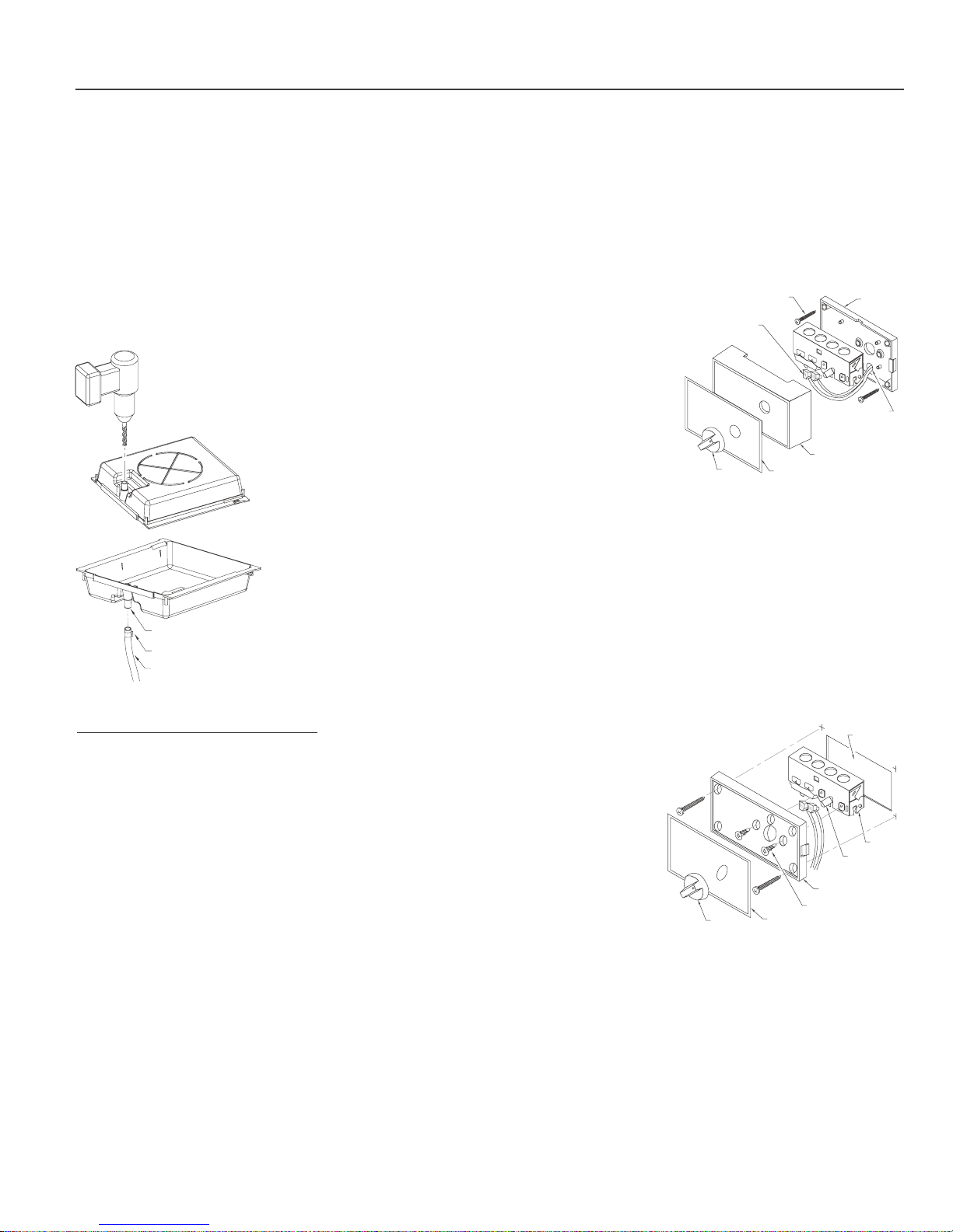
1
3. Referring to figure 26, first drill a small hole (
/8” dia) centered
from the bottom of the drain fitting up through the pan.
3
Figure 26
4. Then using a
carefully enlarge the hole to allow
/8” drill bit
for free flow of water.
5. Once the drain fitting has been
drill and the water pan installed
onto the furnace you may install
5
the drain tube (
/8”OD,1/2”ID)
not supplied.
6. First install a5/8”hoseclamp
(not supplied) over the end of the
drain tube, then push the drain
tube up over the drain fitting and
secure in place with the hose
clamp. (Fig. 27)
DRAIN FITTING
HOSE CLAMP
DRAIN HOSE
Figure 27
7. Feed the other end of the drain
tube to a floor drain, secure to the
floor drain using a tie strap or
cable tie (not supplied).
STEP #5: ELECTRICAL INSTALLATION
This unit is supplied with a 24 volt plug in transformer. The
transformer must be plugged into a constant (one that will not be
shut off) 120 volt outlet. The transformer is supplied with 10 feet
of low voltage wire which must feed the humidistat and the
humidifier’s drum motor. Select an outlet within the 10 feet.
HUMIDISTAT
The humidifier is supplied with an exclusive universal humidistat
which can be either wall mounted as furnished or, with a few
minor changes, be mounted on the return (cold) air plenum/duct.
Either wall mounting or plenum/duct mounting works equally
well for humidity sensing and control. Wall mounting provides
easy access to adjust the humidistat setting since it is located in
the living area. Plenum/Duct mounting provides a simple
installation (you should not have to purchase extra low voltage
wire or fish the wires through the wall).
installations, the humidistat is installed near the heating
thermostat for easy adjustment and wiring.)
3. Because the humidistat will be located further away from the
humidifier you will have to purchase approximately 15 to 20
feet of 20 ga low voltage wire.
4. Drill a small hole in the wall and then fish the low voltage wire
out thru the hole. Leave approximately 6 inches of low voltage
wire leads outside the hole for humidistat connection.
5. Remove the cover plate
from the humidistat and
you will see four holes
at the corners of the
base plate mount the
90˚ WIRE TERMINALS
FOR LOW VOLTAGE
WIRE CONNECTIONS
4 SCREWS PROVIDED
FOR MOUNTING TO
THE WALL
BASE
PLATE
humidistat on the wall
using the (4) 1” long
screws provided. Make
sure it is level and the
3/8” HOLE
low voltage wire is
coming out thru the
3
/8”
hole on the base plate.
(Fig. 28)
KNOB
CONTROL
LABEL
COVER
PLATE
Figure 28
6. Strip the low voltage wires and make connections to the
humidistat using the two 90˚ wire terminals provided. Replace
the cover plate.
7. Install the knob onto the humidistat control shaft.
PLENUM/DUCT MOUNTING
1. As shipped, the humidistat is ready for wall mounting. You
must first convert the humidistat from wall mounting to
plenum/duct mounting. The control mechanism must be in
the air stream in order to sense and control the humidity.
2. Remove the cover plate and discard it.
3. Remove the control
mechanism from the
Figure 29
PRE-CUT
PLENUM
HOLE
base plate by removing
the two holding screws
at the back, and then,
turning the control
mechanism 180˚
upside down to allow
the shaft to protrude
1
out through the
/2”
hole on the base plate
(NOTE: base plate
remains in the same
KNOB
CONTROL LABEL
CONTROL
MECHANISM
SHAFT
BASE PLATE
HOLDING SCREWS
position and only the control mechanism is turned (Fig. 29).
4. Replace the two screws to hold the control mechanism to the
base plate.
5. Attach the two 90˚ electrical terminals to the humidistat.
WALL MOUNTING
1. Your humidistat is furnished in the “wall mounting” mode, no
changes to the humidistat are necessary, because the circuit is
low voltage (24 V), no switch box is required.
2. Select a location about five (5) feet above the floor on an inside
wall where normal air circulation exists. (In most residential
6. Use adhesive tape (not provided) to affix the humidistat
opening template to the pre-selected location and then drill
3
the 4 mounting holes and a
/8” hole in the area mark
humidistat cutout.
3
7. Using the
/8” hole as a starting point make the cutout cutting
on the outside of the line.
8. Skip to low voltage wiring section.
Page 8
Furnace Humidifier
8
LOW VOLTAGE WIRING
The 24 volt plug in transformer has 10 feet of low voltage wire
attached. Your 120 Volt outlet should be located close enough to
connect the end of the low voltage wire to the drum motor and have
the duct mounted humidistat located in between. DO NOT PLUG
THE TRANSFORMER IN UNTIL INSTALLATION IS COMPLETE.
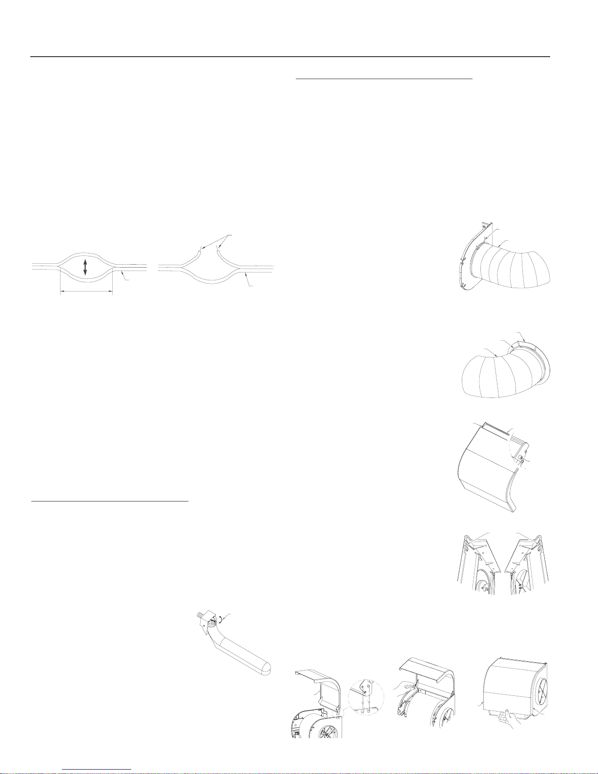
1. The humidifier motor lead wire has two push-on terminals
which will mate with the 2 terminals at the end of the low
voltage wire on the transformer. Connect these wires together.
2. In the area where the humidistat is to be mounted position the
low voltage wire harness and carefully separate the 2 wires
apart. (Fig. 30)
3. Cut one of the conductors and strip the insulation from both
ends. (Fig. 31)
Figure 30
CUT THE MIDDLE AND
SEPARATE APPROX. 3”
LOW
VOLTAGE
WIRE SET
Figure 31
CUT ONE OF THE
CONDUCTORS AND
STRIP THE ENDS
LOW
VOLTAGE
WIRE SET
4. Connect the stripped ends to the 90˚ terminals on the
plenum/duct mount humidistat or to the low voltage wire from
the humidistat wall mounted in the living area (depending on
which humidistat installation you chose).
5. Complete the installation of the Duct mounted humidistat.
6. Mount the humidistat onto the return duct by using the four 1”
long sheet metal screws provided (Note the small rectangular
notch at the bottom provided for the access of the low voltage
wire to the humidistat wiring terminals.)
7. Remove the paper backing from the control label and apply
the label onto the face of the base plate.
8. Install the knob onto the humidistat control shaft.
STEP #6: ADJUSTING THE WATER LEVEL
TURNING THE WATER ON
1. Turn on the water supply at both the main water supply and
the self-piercing saddle valve. Check to see if water leaks at
any joints. If there is a leakage, tighten the compression nut to
correct the problem.
2. Water should flow gently into the water pan. If it flows too slow
or too fast, adjust the self-piercing saddle valve.
ADJUSTING THE WATER LEVEL
KNOB
(ROTATE TO ADJUST
THE WATER LEVEL)
1. The water level is adjusted by
altering the height of the float.
STEP # 7: COMPLETING THE INSTALLATION.
CHECK THE ELECTRICAL WIRING
1. Plug the transformer in and turn up the humidistat to that it is
calling for humidity, 50% +.
2. The drum should start rotating – either direction is fine.
3. Adjust the humidistat down to the off position and the
humidifier will shut off.
INSTALLING THE BYPASS TUBE
4. Retrieve the flexible bypass tube and
two spring clamps
5. Install the bypass tube on the bypass
collar and damper first.
Figure 33
SPRING CLAMP
FLEX TUBE
6. Slide one of the 6” spring clamps
supplied over one end of the bypass
tube. (Fig. 33)
7. Slide this same end of the bypass
tube over the flange of the collar and
secure inplace with the spring clamp.
(Fig. 34)
8. Slide the other 6” spring clamp over
COLLAR FLANGE
SPRING CLAMP
FLEX TUBE
Figure 34
the other end of the bypass tube.
9. Slide this end of the bypass tube onto
the humidifier’s bypass side panel and
secure in place with the spring clamp.
INSTALLING THE FRONT COVER
10. Retrieve the humidifier’s front cover.
MOUNTING
PEG
FRONT
COVER
11. At the top rear of the front there are
2 mounting pegs (Fig. 35). These pegs
will fit into round slots at the top/rear
MOUNTING
PEG
of both side panels (Fig. 36).
12. With the front cover in the fully
open position (not attached to the
humidifier), tilt the cover at approx
a 30˚ angle and insert one of the
ROUND SLOT FOR
FRONT COVER
Figure 35
front cover pegs into the round slot
(Fig. 37).
13. To finish installing the front cover
slightly deflect the top/rear of the
opposite side panel and insert the
other peg into the round slot (Fig. 38).
Figure 36
14. With the front cover installed grasp the bottom and pull down
until fully closed, it will snap closed at the bottom (Fig. 39).
Installation is now complete. Move to humidifier operation section.
2. Rotate the knob of the valve seat
(Fig. 32).
Figure 32
3. Adjust the float in such away so that it closes the automatic
valve when the selected water level has been reached.
4. The maximum water level in the pan should not exceed
from the top of the water pan.
INSTALL COVER FULLY
OPEN AT 90˚ ANGLE
1
/2”
Figure 37
Figure 38 Figure 39
SNAP
CLOSED
SNAP
CLOSED
Page 9

Furnace Humidifier
9
HUMIDIFIER OPERATION
ROTATING DRUM HUMIDIFIER
Because this rotating drum humidifier utilizes a water
pan/reservoir the unit is 100% efficient, all the water used is
delivered to the air. For this reason the unit does not have to be
interlocked with the furnace cycles, the drum can rotate
whether the furnace is heating or not, no water will be wasted
and the humidistat will control the amount of moisture
delivered to the air.
CONTROLLING THE HUMIDITY LEVEL
The mechanical humidistat supplied with this unit is to control
the amount of moisture added to the air in your home – It will
sense the relative humidity level in the air and work as an
ON/OFF switch to control the humidifier, regardless of whether
the furnace is running.
At the beginning of the heating season it may take sometime to
build up the relative humidity level in your home to the desired
level – For the first few weeks turn the humidistat up high to
ensure the humidifier will run. After you feel that you have
achieved the desired relative humidity level turn the humidistat
down until it cycles the humidifier OFF. The humidifier will then
work to maintain the relative humidity at that level.
RECOMMENDED MANUAL HUMIDISTAT SETTINGS
OUT SIDE AIR TEMPERATURE MAXIMUM RELATIVE HUMIDITY SETTING
-20°F /-30°C 15%
-10°F /-25°C 20%
0°F / -20°C 25%
+10°F/ -10°C 30%
+20°F/ -5°C 35%
30%F/ 0˚C 40%
ABOVE 45% MAXIMUM
If condensation continues to form on windows at these settings
reduce the humidistat setting by successive 5% increments. After
each reduction in setting allow 6 hours for equilibrium to be
reached before readjustment.
If condensation persists with progressively lower settings made
during a 3 day period turn off the water supply at the saddle
valve, turn the humidistat to OFF and consult your heating
contractor.
When your house is unoccupied for longer than 3 days during
the winter always set the humidistat down to 15% so that severe
weather during your absence will not result in condensation
which may cause damage to your home.
ACHIEVING AND MAINTAINING A HUMIDITY LEVEL
Outside conditions are the primary factor affecting the humidity
level in your home. The colder it gets outside the less moisture
the outside air will have, your home brings in the outside air
and the humidifier will work to add moisture to it. As outside
conditions change the humidity level in your home will change
as well. Other factors which will affect humidity levels in the
home include, how many air-changes your ventilation system
delivers, the amount of people occupying the home, air leaks,
the use of showers, exhaust fans, HRV’s, and the use of
fireplaces or wood stoves.
SAFELY OPERATING A FURNACE HUMIDIFIER
Proper control of the relative humidity level in the home is key to
ensuring good Indoor Air Quality (IAQ) for your home as well as
protecting against moisture damage.
Although a relative humidity environment of 45 to 50% may be
desirable, setting your humidistat at that point when outside air
temperatures are below 30˚F (-1˚C) can cause condensation on
windows and walls. Continued condensation for extended
periods of time may result in structural damage. Use the chart
below as a guide for maximum relative humidity settings at the
different outdoor air temperatures.
SUMMER SHUT DOWN
During the summer season the humidity level in the air is quite
high. Therefore it is advisable to shut off the humidifier system.
Complete the following steps at the end of the winter season.
1. Close the water supply at the saddle valve.
2. Turn the humidistat knob to the OFF position.
3. Empty and clean the water pan.
4. Close the bypass air damper.
CARE AND MAINTENANCE
Because drum humidifiers utilize a water pan/reservoir they are
susceptible to water deposits and mineral build up, for this reason
we strongly recommend that the yearly maintenance include
• Replacing the evaporator pad
• Cleaning/replacing the float & valve assembly
• Cleaning/replacing the water pan
If you complete all the above tasks at once the amount of time
involved will be greatly reduced and your humidifier will
continue to work at peak efficiency.
Page 10
Furnace Humidifier
10
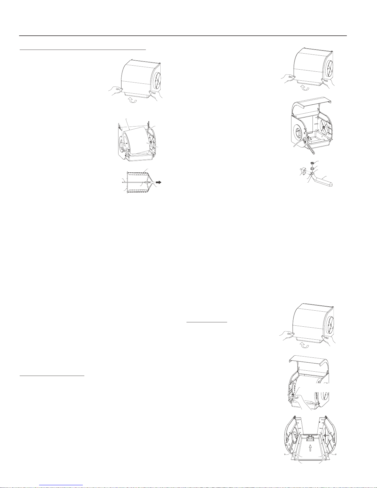
CLEANING OR REPLACING THE EVAPORATOR PAD
(Figures 40 a, b, c)
To clean or replace the
Figure 40
a)
evaporator pad follow the steps
below.
NOTE: Do not rotate the drum
assembly by hand this may
cause damage to the gears in
the drum motor.
1. Unplug the transformer (turn
power off to the humidifier).
2. Turn off the water supply at
the saddle valve.
3. Open the humidifier front
Cover (Fig. 40a). The cover is
snap closed on the left hand
side, to release slightly
deflect the front cover flange
at the bottom left and lift up.
In the fully open position the
DEFLECT
LEFTHAND
FLANGE OUT
DRUM EVAPORATOR PAD ASSEMBLY
b)
c)
DRUM
SHAFT
STOP LUGS
DISK
FLANGE
SPOKES
DEFLECT
RIGHTHAND
FLANGE OUT
OPEN
END
FIRST
TILT
ASSEMBLY
OUT
PULL OUT
BUSHING
cover will stay open.
4. Gently remove the drum/evaporator pad assembly at the
bearing end (open end) first. Take care not to lose the bearing
which the drum shaft rides in. Once the bearing side is
removed you will be able to tilt the drum/evaporator pad
assembly out from the motor coupling. (Fig. 40b)
5. Hold the drum assembly in a horizontal position and pull the
bushing out with your fingers (Fig. 40c).
6. Slide the evaporator pad off the drum cage.
7. To replace the pad keep the bushing in the extended position
and slide the evaporator pad over the spokes until it is against
the disc flange.
8. Push the bushing back along the shaft to the stop lugs. The
evaporator pad is now locked into position.
9. Replace the drum/evaporator pad assembly completing step 4
in reverse motor coupling end first.
10. Close the front cover.
11. Turn on the water supply and plug the transformer back in.
CLEANING OR REPLACING THE FLOAT VALVE
ASSEMBLY/COMPONENTS
(Figures 41 a, b, c)
To clean or replace the float valve assembly/components follow
the steps below.
1. Unplug the transformer (turn power off to the humidifier).
2. Turn off the water supply at the saddle valve.
3. Open the humidifier front Cover (Fig. 41a). The cover is snap
closed on the left hand side, to release slightly deflect the front
cover flange at the bottom left and lift up. In the fully open
position the cover will stay open.
4. If you wish to replace the entire float valve assembly included
valve jet shield, disconnect the
water supply from the valve’s
Figure 41
a)
threaded inlet by using an
adjustable wrench to loosen
and remove by hand (Fig. 41b).
5. Loosen the white mounting
nut using an adjustable
wrench and remove by hand.
You can now remove the float
and replace with a new one.
DEFLECT
LEFTHAND
FLANGE OUT
b)
DEFLECT RIGHTHAND
FLANGE OUT
6. Re-attach the components in
reverse order as above.
7. Turn the water back on and
check for and repair any leaks.
8. Plug the transformer back in.
9. To replace or clean selected
components of the float valve
assembly (Fig. 41c), Place your
thumb and forefinger around
the neck of the float.
c)
VALVE JET
SHIELD
PIVET PIN
SQUEEZE
HERE (NECK)
KNOB
VALVE SEAT
SPIGOT
FLOAT
10. Squeeze firmly. This will disengage the two pivot pins from the
holes at the sides of the valve jet shield and release the float.
11. The valve seat and knob can then be pulled off the spigot.
12. When replacing the valve seat be sure that it is pushed down
as far as it will go onto the float.
13. Clean components or replace with new parts and reassembly
the float.
14. The float valve assembly can be cleaned by using a solution
of 50/50 water and vinegar.
15. Close the front cover.
16. Turn on the water supply and plug the transformer back in.
CLEANING OR REPLACING
Figure 42
a)
THE WATER PAN
(Figures 42 a, b, c)
To clean or replace the water pan
follow the steps below.
1. Unplug the transformer (turn
power off to the humidifier).
DEFLECT
LEFTHAND
FLANGE OUT
b)
DEFLECT RIGHTHAND
FLANGE OUT
2. Turn off the water supply at
the saddle valve.
3. Open the humidifier front
THUMB AND FOREFINGER
SQUEEZE HERE
Cover (Fig. 42a). The cover is
snap closed on the left hand
side, to release slightly deflect
the front cover flange at the
c)
bottom left and lift up. In the
fully open position the cover
will stay open.
4. To remove the float from the
jet shield place your thumb
and forefinger around the
DEFLECT
SLIGHTLY
SIDE PANEL
SLOT
WATER PAN HOOK
DEFLECT
SLIGHTLY
Page 11

Furnace Humidifier
11
neck of the float squeeze firmly and this will disengage the 2
pivot pins from the holes at the sides of the valve jet shield.
(Fig. 42b)
5. Remove the drum and evaporator pad assembly bearing end
first (see instructions above).
6. Remove the two screws which secure the water pan to the side
panels, the screws are located at the front, on the underside of
the water pan’s side flanges. There is also a set of hooks on
either side of the front of the pan which fit into slots on both
side panels, to release the water pan deflect each side slightly
in the area where the pan attaches and lift up. (Fig. 42c)
7. Once removed from the slots the pan will slide out.
8. Clean in a 50/50 mixture of water and vinegar.
9. Replace all components in reverse order
10. Close the front cover.
11. Turn on the water supply and plug the transformer back in.
WARRANTY
The manufacturer guarantees the for the period of one year from
the date of purchase, the product will be free of defects in
workmanship and/or material. As well the manufacturer offers a
life time warranty on the flow through humidifier body. During
the warranty period, we will replace or repair any defective part
at no charge if the product is returned prepaid to our factory.
NOTES
This warranty does not cover any labor or shipping costs, or the
cost of replacement components as part of routine maintenance
(such as Flow Through Humidifier Evaporator Pads, Inlet water
Filters, or Orifice Fittings). Any damage or failure caused by
abuse, misuse, abnormal usage, faulty installation, or improper
maintenance will not be covered by this warranty.
In order to make a claim on this warranty you must be the
original consumer of the product and you must contact the
manufacturer 1-800-465-7300 between 8 AM and 3:30 PM EST
Monday to Friday at the first sign of a defect. You will be required
to present to the manufacturer the original bill of sale showing
date of purchase, place of purchase, and model purchased.
Failure to meet these requirements will void your warranty.
The manufacturer will not be held responsible for any bodily
injuries or damages to personal property or real estate whether
caused directly or indirectly by the product. Some states and
provinces do not allow the exclusion or limitation of incidental or
consequential damages and some states or provinces do not
allow limitations on how long an implied warranty lasts, so these
exclusions or limitations may not apply to you. This warranty
gives you specific legal rights and you may have other rights
which vary from state to state and province to province.
SAVE THIS DOCUMENT AND ATTACH YOUR RECEIPT.
Date of Purchase Date Of Installation
Place of Purchase Brand and Model#
Page 12
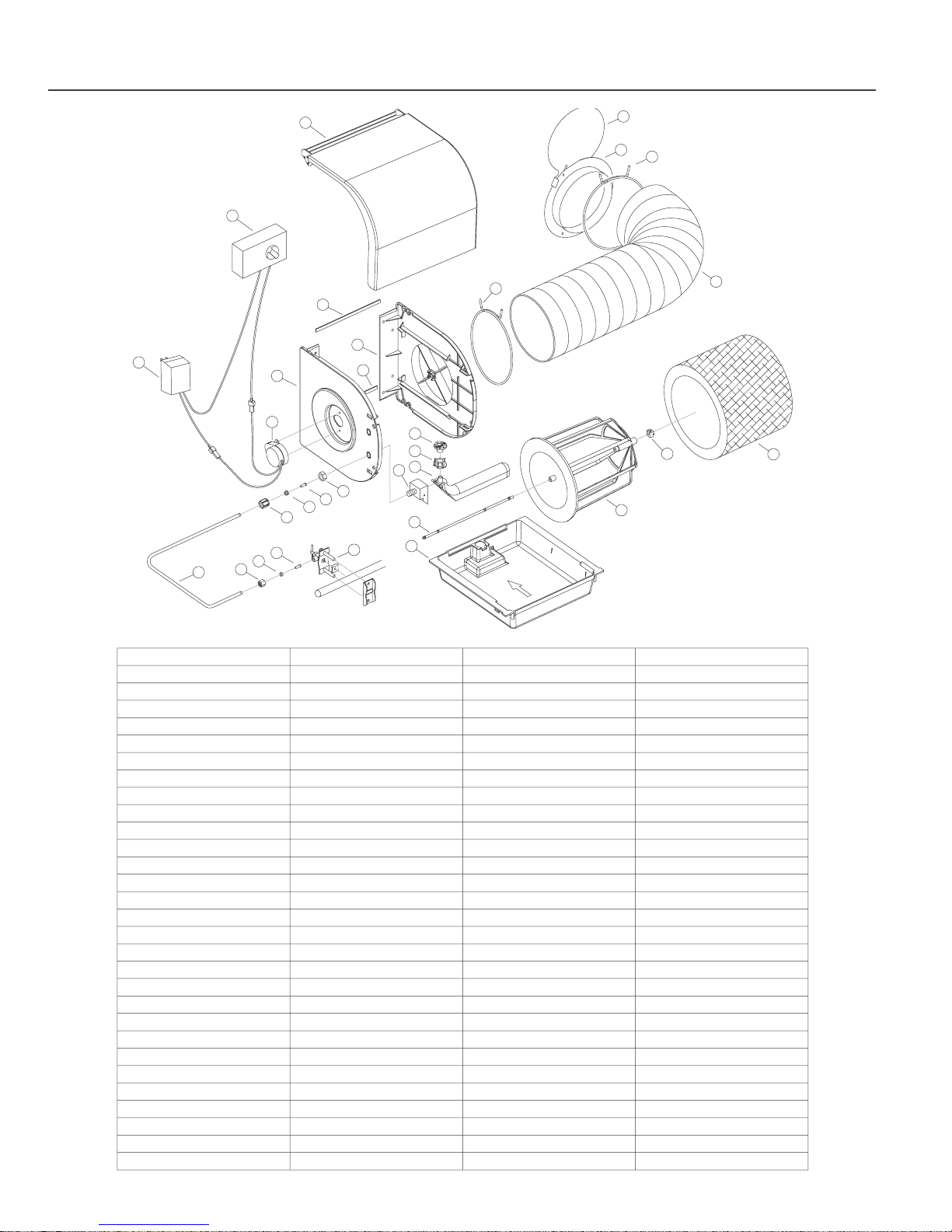
Furnace Humidifier
12
1
2
27
6
7
3
17
5
4
15
16
14
19
18
8
9
10
11
12
13
14
22
20
21
29
28
27
26
24
23
25
MODEL 1000
ITEM NUMBER
1
DESCRIPTION
cover (specify brand)
2 humidistat (specify brand)
4
5
motor side panel
6
7
bypass side panel
8
9
10
water level knob
water level knob seat 1/per 01A017084
11
12
13
14
15
16
17
18
nylon compression nut
1/4" plastic water tubing
nylon compression nut 1/per 060010801
19
20
needle valve assembly
21
22
23
24
25
evaporator water pad
26
6" spring wire clamp 2/per 01093800027
28
29
QTY/UNIT
1/per
1/per
PART NUMBER
011483000
01A000000
0109160011/per120/24VAC transformer3
motor
1/per
1/per
01A172235
011481000
tesa foam 8 inches/unit 20221
1/per
011482000
tesa foam 6 3/4 inches/unit 20221
1/per
01A017083
float 1/per 01A900903
jet shield 1/per 01A900906
nylon hex nut
brass insert 01A930041
rubber ferrule
1/per
1/per
1/per
1/per
10 feet/unit
1/pernylon ferrule
1/per
water pan
drum shaft 01A900911
drum cage
bearing
1/per
1/per
1/per
1/per
1/per
060011142
01A010816
0600110801
01A930040
010926001
0PB132055
011484000
01A900914
011509000
01A017256
by-pass tube 3 feet/unit 010917000
collar
air damper
1/per
1/per
01A172107
01A170930
 Loading...