

Drummond Nanoject II Instruction Manual
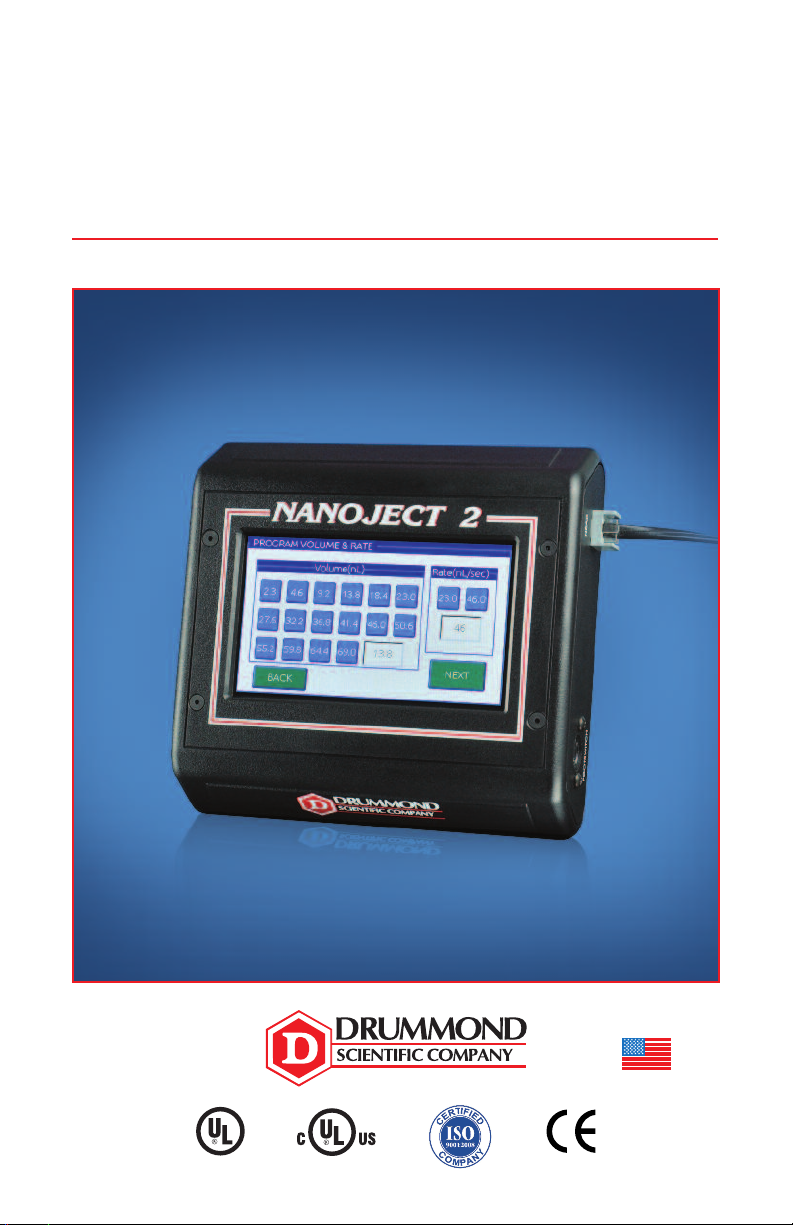
Nanoject II
MADE IN USA
Digital Control Box
INSTRUCTION MANUAL • 3-000-029-D
LABORATORY EQUIPMENT
E21997
Rules for Safe Operation
• For indoor use only.
• Never operate unit in an explosive atmosphere.
• Do not operate unit with a damaged cord.
• Use power source only in a standard electrical outlet.
• Do not handle power source with wet hands.
• Do not put unit or power source in water or other liquid.
• When servicing, use only identical Drummond replacement parts.
• Save these instructions.
If the equipment is used in a manner not specified by the manufacturer,
the protection provided by the equipment may be impaired. Always use
the power source that is supplied with the unit.
Connections to Power Source:
Check the power source to see that the line voltage corresponds to the voltage
indicated on the mains adapter.
If the mains adapter source and the line voltage are not compatible, the electrical
components of the Nanoject II may be damaged or destroyed.
Before each use, confirm that the mains adapter cable is not damaged, worn or
severely buckled and there are no breaks in the insulating surface. If any damage is
noted, do not use the Nanoject II until the damaged main is replaced.
Connecting to power outlet: The control box has a power source transformer
attached to the box. Plug this into your outlet using the correct adapter supplied.
There is an “on/off” switch on the side of the control box which turns on the control
box once the injector head is attached. To turn off, use the switch to turn off. If you
want to disconnect the power from the unit, merely unplug the transformer from the
wall outlet.
Power/Current Rating: AC 100~V, 50-60 Hz, 38VA DC 12V 2A
Input: 100-240~V, 50-60 Hz, 0.6A
Output: 12V 2A
Specifications for Usage
This unit is intended to be used to inject nanoliter quantities of sample.
This equipment is for indoor use only.
Temperature Range 10°C–35°C, Maximum Humidity 60%
FAILURE TO USE THE EQUIPMENT IN ACCORDANCE WITH INSTRUCTIONS
OR MODIFYING THE EQUIPMENT WILL VOID WARRANTIES.
CAUTION: CAREFULLY READ THROUGH THIS ENTIRE MANUAL BEFORE USING
YOUR NANOJECT II. PAY CLOSE ATTENTION TO THE RULES FOR SAFE
OPERATION WARNINGS AND CAUTIONS.
2

Introduction
Thank you for purchasing the Nanoject II Control Box by Drummond Scientific Company.
This device can be used immediately after purchase. A summary of how to operate the
device is provided in this quick instruction manual.
Accessories available for purchase:
Replacement Glass 3.5˝ (vial of 100) . . . . . . . . . . . . . . . . . . . . . . . .3-000-203-G/X
Replacement Glass 7˝ (vial of 100) . . . . . . . . . . . . . . . . . . . . . . . . .3-000-203-G/XL
O-ring Kit with Collet . . . . . . . . . . . . . . . . . . . . . . . . . . . . . . . . . . . . .3-000-002-KN
Wire Plunger (replacement) . . . . . . . . . . . . . . . . . . . . . . . . . . . . . .3-000-000-203-X
30G/2˝ Needle . . . . . . . . . . . . . . . . . . . . . . . . . . . . . . . . . . . . . . . . . . .3-000-027
Footswitch . . . . . . . . . . . . . . . . . . . . . . . . . . . . . . . . . . . . . . . . . . . . . .3-000-032
(remote capability for fill, empty and inject functions)
Micromanipulator, MM33 (right hand) . . . . . . . . . . . . . . . . . . . . . . . . . .3-000-024-R
(left hand) . . . . . . . . . . . . . . . . . . . . . . . . . . .3-000-024-L
Support Base . . . . . . . . . . . . . . . . . . . . . . . . . . . . . . . . . . . . . . . . . .3-000-025-SB
Magnetic Base . . . . . . . . . . . . . . . . . . . . . . . . . . . . . . . . . . . . . . . . .3-000-025-MB
Universal Adapter . . . . . . . . . . . . . . . . . . . . . . . . . . . . . . . . . . . . . . . .3-000-024-A
Technical Specifications
Part Number . . . . . . . . . . . . . . . . . . . . . . . . . . . . . . . . . . . 3-000-029-D
Power Source . . . . . . . . . . . . . . . . . . . . . . . . . . . . . . . . . . . . 100/240 volt, 50/60 Hz
Total Sample Volume . . . . . . . . . . . . . . . . . . . . . . . . . . . . . 4.2 nL
Fill Volume Speed . . . . . . . . . . . . . . . . . . . . . . . . . . . . . . . . 23 nL or 46 nL/sec
Empty Volume Speed . . . . . . . . . . . . . . . . . . . . . . . . . . . . . 92 nL/sec (only)
Injection Rate . . . . . . . . . . . . . . . . . . . . . . . . . . . . . . . . . . . 23 nL or 46 nL/sec
Volume Range . . . . . . . . . . . . . . . . . . . . . . . . . . . . . . . . . . 2.3 nL - 69.0 nL
Plunger Travel . . . . . . . . . . . . . . . . . . . . . . . . . . . . . . . . . . 27 mm
Glass Micropipette Dimensions . . . . . . . . . . . . . . . . . . . . . . OD 0.045˝ (1.14 mm)
ID 0.021˝ (0.53 mm)
Control Box Dimensions
Weight: . . . . . . . . . . . . . . . . . . . . . 0.43 kg
Length: . . . . . . . . . . . . . . . . . . . . . 14 cm
Width: . . . . . . . . . . . . . . . . . . . . . . 13.5 cm
Thickness: . . . . . . . . . . . . . . . . . . 4 cm
3

Quick Start Guide
1) Plug the injector cable into the “HEAD” port on the right side of the control box.
2) If using the footswitch, insert the footswitch cable into the “FOOTSWITCH” port on
the right hand side of the control box.
3) Plug the control box into a standard electrical outlet using the appropriate
adapter head on the power supply.
4) Turn on unit with the on/off switch located on the left hand side of the control box.
Initially the Drummond logo will be displayed on the screen followed shortly by the
Operational Mode screen.
5) Micropipette Pulling and Backfilling
The Nanoject II requires the use of pulled micropipettes from the glass provided.
Ideally, the tip size should be 10-30 microns in size. The capillary glass provided is
produced from N-51-A material and has a softening point of 780°C. Many researchers
pull the tips and then break them off with forceps. This enables piercing the cell
membrane much easier with no skipping. Once the tips are pulled, they must be
“backfilled” with oil (or other non-compressible fluid) before attachment to the injector.
Silicone or mineral oil is frequently used. Backfilling is facilitated by using the 30 gauge
x 2˝ needle and a syringe. Disposable spinal needles are also frequently used.
NOTE: THE NANOJECT II WILL NOT OPERATE PROPERLY WITHOUT
BACKFILLING THE MICROPIPETTE.
6) Securing the Micropipette to the Injector Standard Collet/O-ring (Fig. 1)
Once the micropipette is backfilled, loosen the collet. The pointed wire plunger should
be positioned so you can just see the tip flush with the end of the collet (slightly
recessed is also acceptable). This is referred to as the “Home” position. Push them
micropipette onto the wire plunger and as you push the tip on, feel it go through the
large O-ring and seat in the white spacer. Once positioned, tighten the collet securely.
Give the micropipette a pull to confirm it is securely mounted. See Fig. 1 for proper
configuration of the O-rings and the white spacer. It is absolutely essential that these
components are properly configured.
NOTE: THE WHITE SPACER HAS ONE FLAT SIDE AND ONE SIDE WITH A
RECESS MACHINED AROUND THE HOLE. THIS RECESS IS TO RECEIVE THE
BACK END OF THE PIPETTE.
4
 Loading...