

Drummond MTL10, MTL20 Instruction Manual
MTL10 & MTL20 TEST LAMPS
Instruction
Manual
ALWAYS READ THESE INSTRUCTIONS BEFORE PROCEEDING
Thank you for buying one of our products. For safety and full
understanding of its benefi ts please read this manual before use.
Technical support is available from 01923 441717 and support@
martindale-electric.co.uk.
CONTENTS
1 Safety Information 1
1.1 Meaning of Symbols and Markings 1
1.2 Precautions 3
2 Introduction 5
2.1 Inspection 5
2.2 Description 5
2.3 Accessories 5
3 Operation 6
3.1 Control Elements and Connections 6
3.2 Description of LED Indicators 6
3.3 Operating Duty Ratio 7
3.4 Proving Check 7
3.5 Testing for the Presence of Hazardous Live Voltage 8
3.6 Push Button Switches (MTL20 only) 9
3.7 Interference (Phantom) Voltage 9
4 Maintenance 11
4.1 Probe Replacement 11
4.2 Periodic Testing 11
4.3 Cleaning 11
4.4 Repair and Service 12
4.5 Storage Conditions 12
5 Warranty 13
Measurement Categories 15
Specifi cations
1
1 SAFETY INFORMATION
REMEMBER: SAFETY IS NO ACCIDENT
These instructions contain both information and warnings that are
necessary for the safe operation and maintenance of this product. It
is recommended that you read the instructions carefully and ensure
that the contents are fully understood. Failure to understand and
to comply with the warnings and instructions can result in serious
injury, damage or even death.
Particular attention should be paid to the Warnings, Precautions and
Technical Specifi cations.
Please keep these instructions for future reference.
Updated instructions and product information are available at:
www.martindale-electric.co.uk
1.1 Meaning of Symbols and Markings
Caution - risk of danger & refer to instructions
Caution - risk of electric shock
Equipment protected by double or reinforced
insulation (Class II)
Suitable for live working
Alternating current (AC)
Direct current (DC)
ON/OFF (push button)
2
CAT III (Measurement Category III) is applicable to test and
measuring equipment connected to the distribution part of
the building’s low-voltage MAINS installation.
CAT IV (Measurement Category IV) is applicable to test and
measuring equipment connected at the source of the
building’s low-voltage MAINS installation.
Equipment complies with relevant EU Directives
End of life disposal of this equipment should be in
accordance with relevant EU Directives
For further information on measurement categories refer to page 15.
3
1.2 Precautions
This product has been designed with your safety in mind, but please
pay attention to the following warnings and cautions before use.
Warnings
In order to avoid the danger of electrical shock, it is important that
proper safety measures are taken when working with voltages
exceeding 30V AC rms, 42V AC peak or 60V DC.
Where applicable other safety measures such as the use of protective
gloves, goggles etc. should be employed.
The voltage indicator must only be used by a skilled and competent
person who is familiar with the relevant regulations, the safety risks
involved and the consequent normal safe working practices.
Before each use the voltage indicator should be examined for
damage, cracks, cuts or scratches to the housing, cable and prods.
The cable has black outer and contrasting inner insulation, to allow
damage to the cable to be easily identifi ed. If there is any doubt the
voltage indicator should
not be used
.
Make sure the voltage indicator is dry, clean and free from dust,
grease and moisture while in use to avoid the danger from electric
shock due to surface leakage.
Before and after each use, the voltage indicator must be proven using
a suitable proving device or a known good voltage source. Do not use
the voltage indicator if any expected LED’s fail to illuminate correctly
during proving.
Testing for a voltage that exceeds the specifi ed limits of the voltage
indicator may damage the voltage indicator and may expose the
operator to a shock hazard. Always check the voltage indicator’s
specifi ed limits before use.
4
The specifi ed measurement category means the voltage indicator
will be safe to the user if connected to a voltage up to 1000V to
earth on a CAT II or CAT III installation and 600V to earth on a CAT
IV installation. It
does not
mean it can be used to test for a voltage
beyond its maximum specifi ed limits.
If using the voltage indicator in falling rain or damp conditions, the
operator must use additional protection to avoid the danger from
electric shock due to surface leakage.
Select appropriate test prods and secure with captive ring nuts. The
L-shaped test prods should be oriented in one of four directions using
the square location feature before it is secured.
When changing or adjusting the prods, ensure that both prods have
been disconnected from any source of power or other equipment.
Always keep your fi ngers behind the fi nger guards. Never touch the
exposed metal prod tips.
The different indicating signals of the voltage indicator (including the
ELV limit indication) are not to be used for measuring purposes.
The voltage indicator must not be dismantled or modifi ed in any way
by unauthorized persons. The safety of the voltage indicator cannot be
guaranteed under such circumstances and it
must not be used
.
Cautions
Avoid severe mechanical shock or vibration and extreme temperature.
If the voltage indicator has been stored or transported in temperatures
outside its normal operating range it should be given suffi cient time to
stabilise in the environment where it is to be used. An acclimatisation
time of at least 2 hours is required prior to operation of the voltage
indicator.
5
2. INTRODUCTION
2.1 Inspection
Examine the shipping carton for any sign of damage. Inspect the unit
and any accessories for damage. If there is any damage then consult
your distributor immediately.
2.2 Description
The MTL10 and MTL20 test lamps are two-pole voltage indicators
for universal applications. They are designed to be used by
skilled persons in accordance with safe methods of work, and are
constructed in accordance with the applicable safety standards to
provide safe and reliable indication.
The MTL10 and MTL20 have the following features:
AC and DC Voltage tests up to 500V AC and 750V DC
Bright LED indication
Full voltage indication function without batteries
PTC thermistor fi tted in probe to limit current in the event of cable
damage
Contrasting colour of inner sheath to highlight cable damage
Ergonomic and robust housing
Probe tips comply with GS38
Measurement Category CAT IV 600V, CAT III 1000V
Constructed in compliance with EN 61243-3
IP64 rated environmental protection for internal electronics
2.3 Accessories (included)
2pc. Straight prod
1pc. L-shaped prod
Instructions
6
3. OPERATION
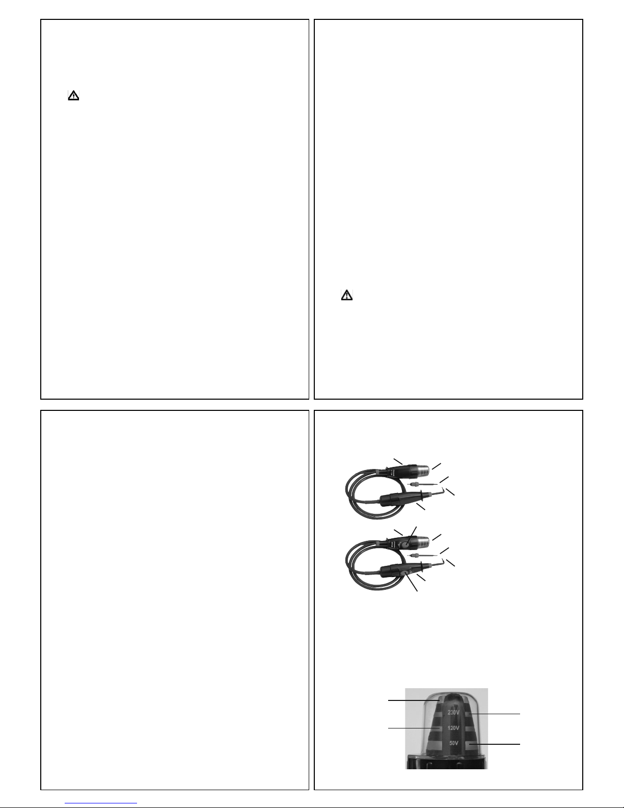
3.1 Control Elements and Connections
MTL10
MTL20
A - Instrument body
B - LED indicator bands
C - Probe handle
D - Straight prod
E - L shaped prod
F - Switches (MTL20 only)
3.2 Description of LED Indicators
400V band
F
A
C
D
E
B
A
C
D
E
B
F
120V band
230V band
50V band
 Loading...