

Drummond MRB-36HWN1-X14B, MRB-60HWN1-X14, MRB-48HWN1-X14 Installation Instructions Manual
INSTALLATION INSTRUCTIONS
PACKAGE 14 SEER - HEAT PUMP
3 - 5 TONS.
3Ph
MRB-36HWN1-X14B, MRB-48HWN1-X14,
MRB-60HWN1-X14.
R-410A Refrigerant
MAN-I-IDP14HP-1115
RECOGNIZE THIS SYMBOL AS AN INDICATION OF IMPORTANT SAFETY INFORMATION
WARNING
These instructions are intended as an aid to qualified
licensed service personnel for proper installation,
adjustment and operation of this unit. Read these
instructions thoroughly before attempting installation
or operation. Failure to follow these instructions may
result in improper installation, adjustment, service or
maintenance possibly resulting in fire, electrical
shock, property damage, personal injury or death.
DO NOT DESTROY THIS MANUAL
Please read carefully and keep in a safe place for future reference by a serviceman.

TABLE OF CONTENTS
1.0 SAFETY...................................................................................................
1.1 INSPECTION............................................................................................................4
1.2 LIMITATIONS............................................................................................................4
2.0 INSTALLATION...............................................................................................................4
2.1 PRE-INSTALLATION....................................................................................
2.2 CLEARANCE............................................................................................................5
2.3 RIGGING AND HANDING........................................................................................5
3.0 DUCTWORK...................................................................................................................8
4.0 CONDENSATE DRAIN CONNECTION..........................................................................8
4.1 INSTALL DRAIN PIPE……………………………………………….............
4.2 REMOVAL AND CLEAN THE DRAIN PAN………………….....................................9
5.0 FILTERS..........................................................................................................
6.0 ELECTRICAL WIRING.....................................................................................
6.1 POWER WIRING......................................................................................................9
6.2 GROUNDING..............................................................................................
6.3 CONTROL WIRING..................................................................................................9
7.0 AIRFLOW PERFORMANCE................................................................................
7.1 AIRFLOW PERFORMANCE DATA…………………………………...................
8.0 SYSTEM OPERATION………………………………………………………............
8.1 COMPRESSOR CRANKCASE HEATER (OPTIONAL)….......……....................…19
8.2 PROTECTION (FOR HP SYSTEM ONLY).............................................................19
8.3 DEFROST MODE (FOR HP SYSTEM ONLY)……..............………..............
8.4 MANUAL DEFROST MODE (FOR HP SYSTEM ONLY).......……......................…20
8.5 THERMOSTAT SIGNALS.......................................................................................20
8.6 PHASE SEQUENCE PROTECTION......................................................................21
9.0 OPERATION CHECK-UP..........................................................................................
10.0 TROUBLE SHOOTING ...........................................................................................
................3
........
.......
.........
.............4
..........8
......9
.......
.......9
....
..........9
.....
....14
.......14
...
...... 19
.....
.....19
....
...
21
21
LIST OF TABLES
TABLE 2-1 UNIT CLEARANCE………………………………………..………..........…………6
TABLE 6-1 14 SEER HEAT PUMP W/WITHOUT ELECTRIC HEAT……...................…....12
TABLE 6-2 14 SEER COOLING ONLY W/WITHOUT ELECTRIC HEAT..................…
TABLE 6-3 14 SEER PHYSICAL DATA……….................................................…........
TABLE 7-1 SIDE DUCT APPLICATION…………….....…...............…................…...
TABLE 7-2 BOTTOM DUCT APPLICATION……….........………………….............….....…
TABLE 7-3 REFRIGERANT CHARGE FOR H/P SYSTEM.............................…...............16
TABLE 7-4 REFRIGERANT CHARGE FOR H/P SYSTEM.............................…...............16
TABLE 7-5 REFRIGERANT CHARGE FOR H/P SYSTEM.............................…...............17
TABLE 7-6 REFRIGERANT CHARGE FOR H/P SYSTEM.............................…...............17
TABLE 7-7 REFRIGERANT CHARGE FOR H/P SYSTEM.............................…..............18
TABLE 7-8 REFRIGERANT CHARGE FOR H/P SYSTEM.............................…...............18
TABLE 8-1 THERMOSTAT SIGNALS…………………………………………................
......12
…..13
......
.......20
…14
15
LIST OF FIGURES
FIG. 2-1 COMPONENT LOCATION.....………………………………...............…..................5
FIG. 2-2 UNIT DIMENSIONS…………………………………………...................................
FIG. 2-3 DIMENSIONS BACK AND BOTTOM............................………..............................7
FIG. 4-1
FIG. 6-1 TYPICAL FIELD CONTROL WIRING DIAGRAM…………………….....……….....11
FIG. 6-2 TYPICAL FIELD POWER WIRING DIAGRAM…………………………………....
HP SYSTEM WIRING DIAGRAM...................................................................................
REMOVABLE CONDENSATE DRAIN PAN AND REMOVAL PROCEDURE
......................9
...6
...11
.....22
This document is customer property and is to remain with this unit.
These instructions do not cover all the different variations of systems nor
does it provide for every possible contingency to be met in connection with
installation.
All phases of this installation must comply with NA TION, STATE AND LOCAL
CODES. If additional information is required please contact your local
distributor.
1.0 SAFETY
When you see the symbols below on labels or in the manual, be alert to the
potential or immediate hazards of personal injury, property and/or product
damage. It is the owner’s or installer’s responsibility to comply with all safety
instructions and information accompanying these symbols.
WARNING: This is a safety alert symbol indicating a potential hazardous situation, which could result in personal injury, property and/or
product damage or death.
CAUTION: This is a safety alert symbol indicating a potential hazardous situation, which could result in moderate personal injury, and/or
property and product damage.
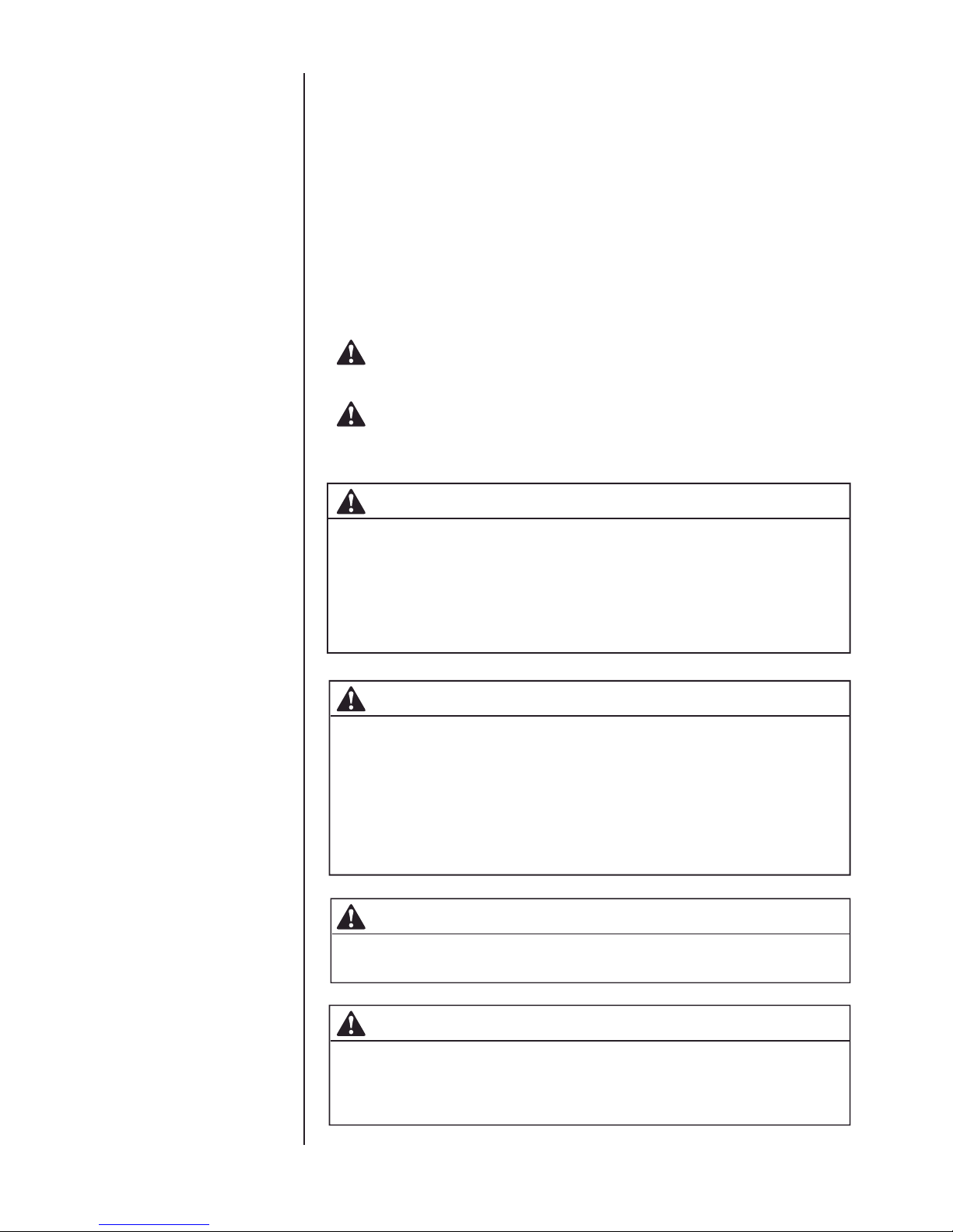
WARNING
These instructions are intended as an aid to qualified, licensed service
personnel for proper installation, adjustment and operation of this unit. Read
these instructions thoroughly before attempting installation or operation.
Failure to follow these instructions may result in improper installation, adjustment, service or maintenance possibly resulting in fire, electrical shock, property damage, personal injury or death.
WARNING
The manufacturer’s warranty does not cover any damage or defect to the
heat pump caused by the attachment or use of any components, accessories or devices (other than those authorized by the manufacturer) into, onto
or in conjunction with the heat pump. You should be aware that the use of
unauthorized components, accessories or devices may adversely affect the
operation of the heat pump and may also endanger life and property. The
manufacturer disclaimer any responsibility for such loss or injury resulting
from the use of such unauthorized components, accessories or devices.
WARNING
Disconnect all power to the unit before starting maintenance. Failure to do
so can result in severe electrical shock or death.
WARNING
Do not, under any circumstances, connect return ductwork to any other heat
producing device such as a fireplace insert, stove, etc. Unauthorized use of
such devices may result in fire, carbon monoxide poisoning, explosion,
property damage, severe personal injury or death.
3
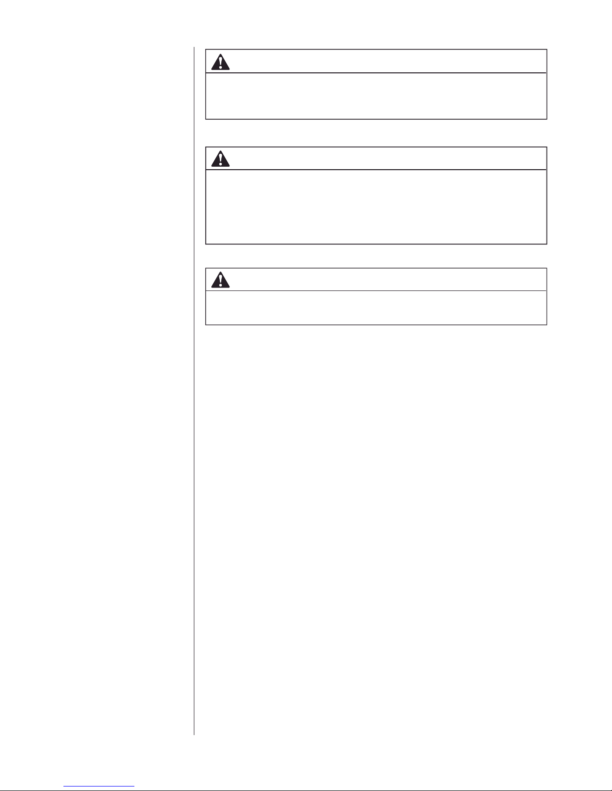
WARNING
The unit must be permanently grounded. A grounding lug is provided. Failure to
ground this unit can result in fire or electrical shock causing property damage,
severe personal injury or death.
WARNING
Only electric heater kits supplied by this manufacturer as described in this
publication have been designed, tested, and evaluated by a nationally recognized safety testing agency for use with this unit. Use of any other manufactured electric heaters installed within this unit may cause hazardous conditions
resulting in property damage, fire, bodily injury or death.
WARNING
Proposition 65: This appliance contains fiberglass insulation. Respirable
particles of fiberglass are known to the state of California to cause cancer.
1.1 INSPECTION
As soon as unit is received, it should be inspected and noted for possible shipping
damage during transportation. It is carrier’s responsibility to cover the cost of
shipping damage. Manufacturer or distributor will not accept the claims from dealer
for any transportation damage.
1.2 LIMITATIONS
Refer to Fig. 2-2, 2-3 for unit physical data and to Table 7-1 for electrical data.
If components are to be added to a unit they must meet local codes, they are to
be installed at the dealer’s and /or the customer’s expense.
Size of unit for proposed installation should be based on heat loss / heat gain
calculations made in accordance with industry recognized procedures identified
by the Air conditioning contractors of America.
2.0 INSTALLATION
2.1 PRE-INSTALLATION
Before installation, carefully check the following:
1. Unit should be installed in accordance with national and local safety codes,
including but not limit to ANSI/NFPS No. 70 or Canadian Electrical Code Part 1,
C22.1, local plumbing and waste water codes and any other applicable codes.
2. For rooftop installation, be sure the structure has enough strength to support
the weight of unit. Unit should be installed on roof curb and leveled.
3. For ground level installation, a level slab should be used.
4. Condenser airflow should not be restricted.
5. On applications when a roof curb is used, the unit must be positioned on the
curb so the front of the unit is tight against the curb.
4
2.2 CLEARANCE
All units require certain clearance for proper operation and service. Refer to
Table 2-1 for the clearances required for construction, servicing and proper
unit operation.
2.3 RIGGING AND HANDING
Exercise care when moving the unit. Do not remove any packaging until the
unit is near the place of installation. Rig the unit by attaching chain or cable
slings to the lifting holes provided in the base rails. Spreader bars, whose
length exceeds the largest dimension across the unit, MUST be used across
the top of the unit.
CAUTION
Before lifting, make sure the unit weight is distributed equally on the rigging
cables so it will lift evenly.
Units may be moved or lifted with a forklift. Slotted openings in the base rails
are provided for this purpose.
CAUTION
All panels must be secured in place when the unit is lifted.
The condenser coils should be protected form rigging cable damage with
plywood or other suitable material.
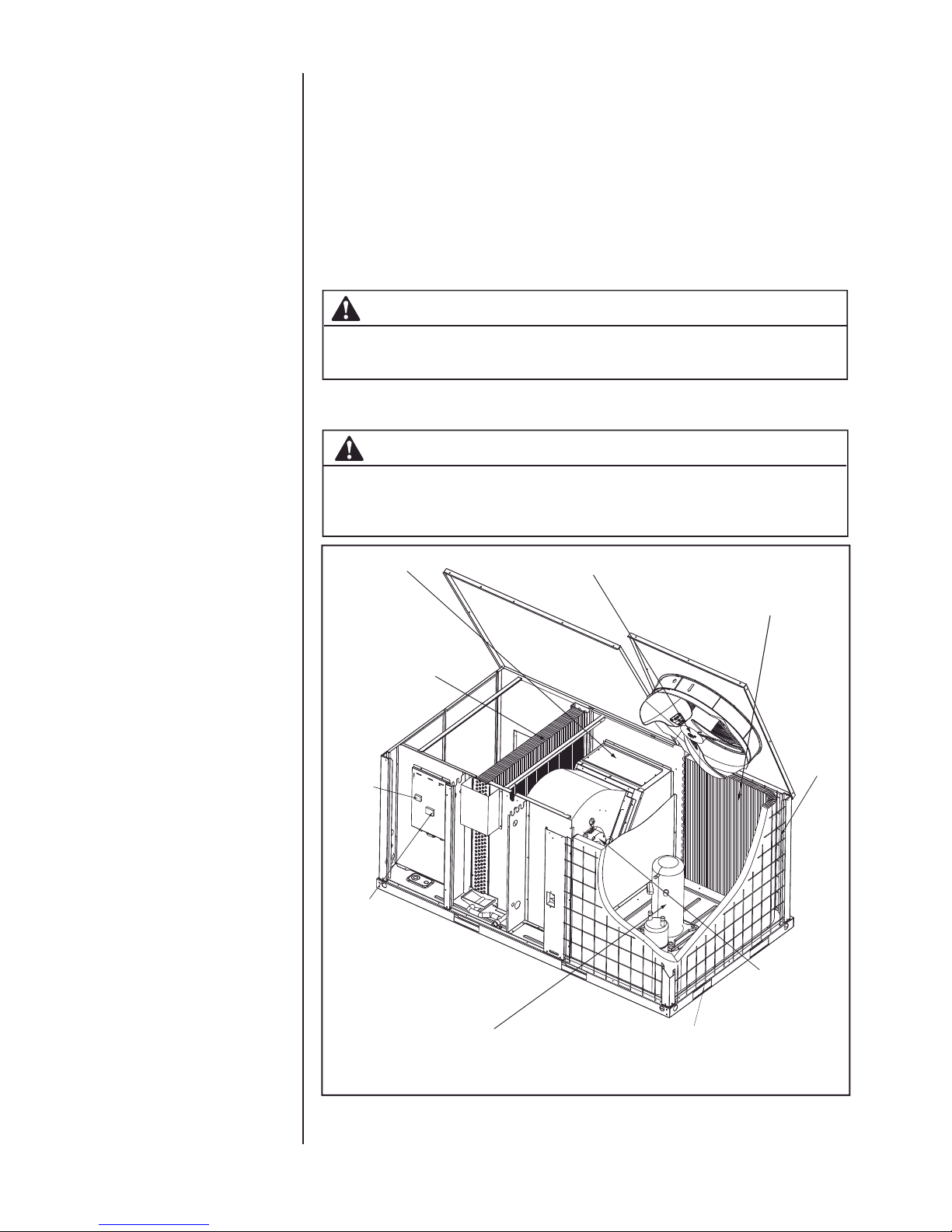
Electric heater assembly (optional)
Highly efficient enhanced
copper tube / aluminum fin
indoor coil
Compressor
contactor
Low voltage
terminal block
Condenser fan motor
Highly efficient enhanced copper
tube/Aluminum fin outdoor coil
Decorative
protective coil
guard
Blower motor with
slide-out blower assembly
Compressor
Fig. 2-1 Component Location
* The above figure for reference purpose only.
Heavy gauge removable
base rails
5
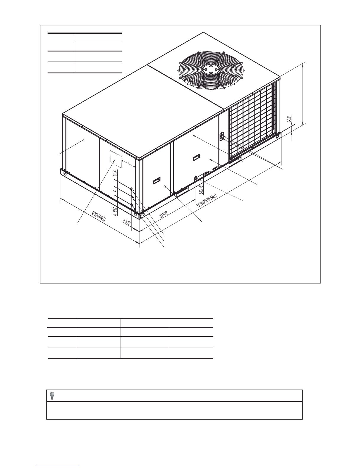
Unit size
Dimensions
A
036
048, 060
Left
Recommended unit
disconnect location
28-3/32”
33-3/64”
6-1/2”
Electrical service access
compapartment panel
High voltage conn. 1-23/64” dia. knockout
Low vlotage entrance 7/8” Dia.
High voltage conn. 1-23/64” Dia.
Front
Drain pan service access
compartment panel
Condensate drain
connection 3/4” NPTI
(Trap required)
A
Hi./Lo. pressure
detected valve
1/4’’ SAE
Fig. 2-2 Unit Dimensions
* The above figure for reference purpose only.
Table 2-1: Unit Clearance
Direction
1
Top
Front
Rear
Distance (in.)
60
30
2
18
Direction
Right
Left
Bottom
3
Duct clearance: 1 inch clearance for all sides of air supply duct.
1. Units must be installed outdoors. Over hanging structure or shrubs should not obscure condenser air discharge outlet.
2. The minimum clearance without economizer/fresh air damper. For distance with Economizer/fresh air damper, please refer
to the relevant Install requiremnt.
Distance (in.)
12
24
0
NOTE
For units applied with a roof curb, the minimum clearance may be reduced from 1 inch to 1/2 inch between
combustible roof curb material and this supply air duct.
6
 Loading...