

Drummond MOV-90CN1-D, MVA-90CWN1-V, MVA-120CWN1-V, MOV-120CN1-D Installation Manual

INSTALLATION MANUAL
SPLIT SYSTEM
COOLING ONLY
MVA-90CWN1-V, MOV-90CN1-D,
MVA-120CWN1-V, MOV-120CN1-D.
R-410A Refrigerant
MAN-I-SSD-1115
CONTENTS PAGE
WARNING
PRECAUTIONS........................................................................................1
ACCESSORIES (INDOOR UNIT).............................................................. 2
INSTALLATING INDOOR UNIT ...............................................................2
INSTALLATING OUTDOOR UNIT............................................................4
HEAT INSULATION OF THE PIPE ............................................................8
INSTALL THE CONNECTIVE PIPE............................................................8
INSTALL THE DRAIN PIPE.....................................................................10
ELECTRIC CONNECTION.......................................................................11
TRIAL RUN .........................................................................................12
MAINTENANCE....................................................................................13
1. PRECAUTIONS
Precautions before reading the installation manual.
Read this user manual carefully before installing the equipment.
The air conditioner must be installed by professional technicians.
When installing the indoor unit and its accessory pipes, adhere to
this user’s manual as far as possible.
Inspect and make sure the piping and cabling are correct before
powering on the air conditioner.
This information may change with the update of this machine, and
no further notice will be given for such change.
Do not throw or slam the remote controller.
Operate the remote controller within the receiving scope of the
indoor unit, and direct the transmitting part of the remote controller to the receiver of the indoor unit.
The remote controller should be over 1m away from the
television or sound box.
Do not place the remote controller at a moist place, near the
heat sources such as stove, or expose it directly in the sunlight.
Ensure correct positive and negative poles when loading the
batteries.
Decide the correct way of conveying the equipment.
Try to transport this equipment with the original package.
If the a ir conditioner needs to be installed on a metal part of the
building, electric insulation must be performed, and the installation must meet the relevant technical standards of electric
devices.
The appliance must be installed 2.3m above floor.
The appliance shall not be installed in the laundry.
Before obtaining access to terminals, all supply circuits
must be disconnected.
The appliance must be positioned so that the plug is
accessible.
The enclosure of the appliance shall be marked by word, or
by symbols, with the direction of the fluid flow.
If the supply cord is damaged, it must be replaced by the
manufacture or its service agent or a similarly qualified
person in order to avoid a hazard.
An all-pole disconnection switch having a contact
separation of at least 3mm in all poles should be
connected in fixed wiring.
The safety precautions listed here are divided into two categories. In
either case, important safety information is listed which must be read
carefully.
WARNING
Failure to observe a warning may result in death.
CAUTION
Failure to observe a caution may result in injury or damage
to the equipment.
After completing the installation, make sure that the unit operates
properly during the start-up operation. Please instruct the customer
on how to operate the unit and keep it maintained.Also, inform
customers that they should store this installation manual along with
the owner's manual for future reference.
CAUTION
Install the unit where enough space of installation and maintenance is available.
Install the unit where the ceiling is horizontal and enough for
bearing the weight of the indoor unit.
Install the unit where the air inlet and outlet are not baffled and
are the least affected by external air.
Install the unit where the supply air flow can be sent to all parts
in the room.
Install the unit where it is easy to lead out the connective pipe
and the drain pipe.
Install the unit where no heat is emitted from a heat source
directly.
Installation Manual
1
Installing the equipment in any of the following places may lead
to faults of the equipment (if that is inevitable, consult the
supplier):
The site contains mineral oils such as cutting lubricant.
Seaside where the air contains much salt.
Hotpring area where corrosive gases exist, e.g., sulfide gas.
Factories where the supply voltage fluctuates seriously.
Inside a car or cabin.
Place like kitchen where oil permeates.
Place where strong electromagnetic waves exist.
Place where flammable ga ses or materials exist.
Place where acid or alkali gases evaporate.
Other special environments.
Install the unit where enough space of installation and mainte-
nance is available.
Install the unit where the air inlet and air outlet are free from
obstacles and strong wind.
3. INSTALLATING INDOOR UNIT
UNIT FEATURES
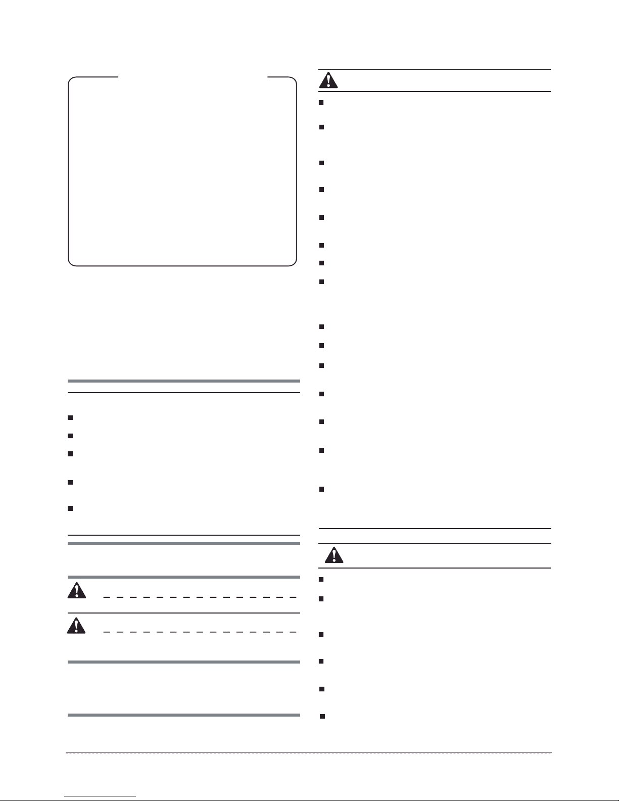
HORIZONTAL OR VERTICAL--All models are designed for either
application and can be installed in either position as supplied from the
factory.
DRAIN PAN (NOT VISIBLE)--The zinc coating steel drain pan is
designed to trap condensate in either vertical or horizontal
installations.All pans are insulated with insulation between the bottom
of the pan and the unit and may be connected for either right or left
hand drains,if unit is to be installed over a finished ceiling and in an
unconditioned space, it is recommended an auxiliary drain pan be
placed under the entire unit.
MANIFOLD--All models are furninshed with dual circuit manifolds for
dual condensing unit application. The circuitry is so arranged to
provide full face coil operation from each unit, Fitting may be installed
for either right or left hand tubing connections.
Install the unit in a dry and well ventilated place.
Install the unit where the bearing surface is level and can bear
weight of the unit, and is suitable for installing the unit horizontally without increasing noise or vibration.
Install the unit where the operation noise and the expelling of air
do not affect neighbours.
Install the unit where no flammable gas is leaked.
Install the unit where it is convenient for pipe connection and
electric connection.
2. ACCESSORIES (INDOOR UNIT)
NOTE
If in the wire control mode, the accessories do not include
display panel assembly remote controller or mounting bracket.
Table 2-1
Accessory name Qty. Purpose
Owner’s manual
Installation manual
refrigerant pipe
refrigerant pipe
Y type refrigerant pipe
Drain outlet
Drain plug
Sealing tape
Plastic ring
Installation Manual
Model
90
120
2
Shape
1
This manual
1
7
6
2
1
1
1
5
Connect to system
Connect to system
Connect to system
Connect to water drainage pipe
Sealing drain
Protect copper pipe and wire
Vertical
Horizontal
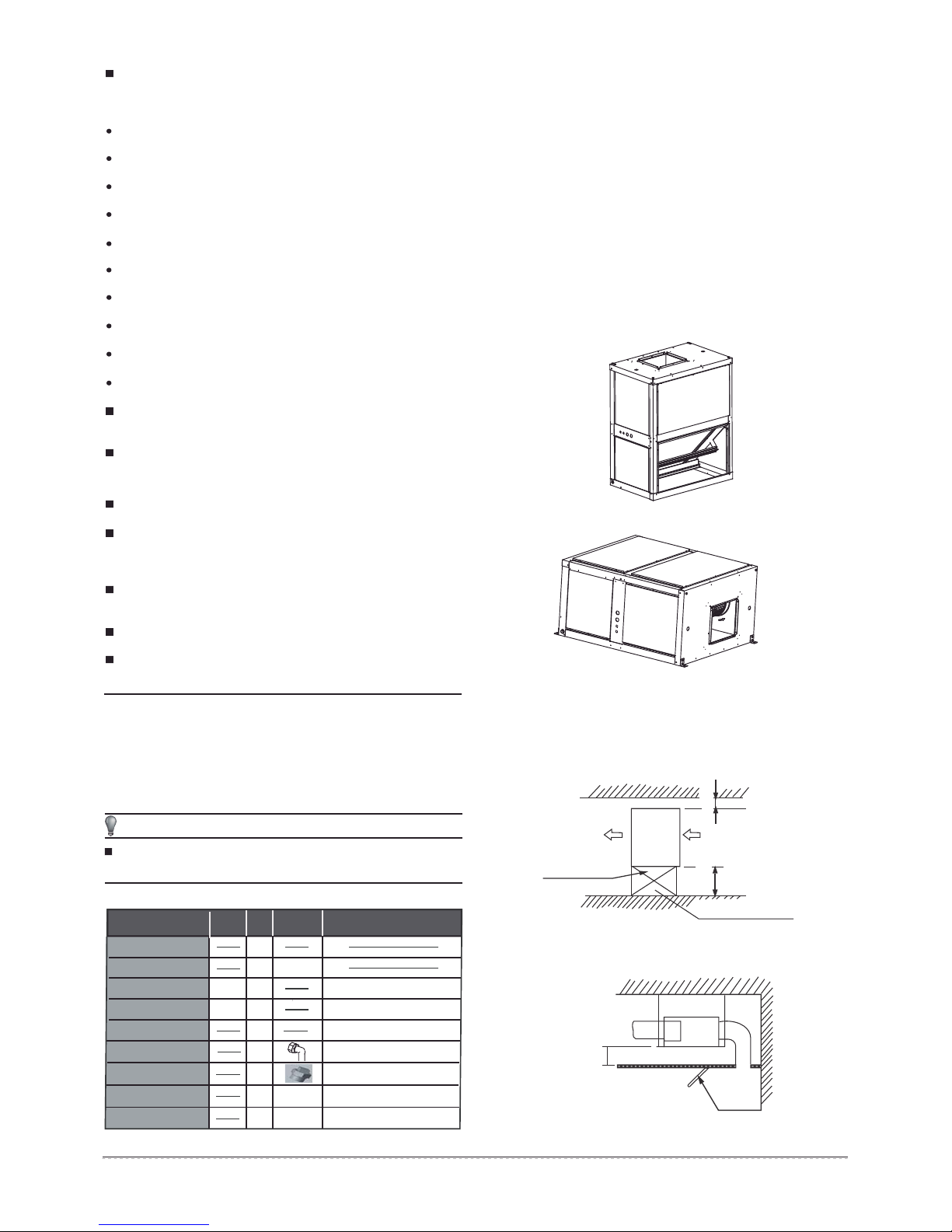
3.1 Installation Space
Ensure enough space required for installation and maintenance.
Over 500 mm
Maintenance space
Over 600 mm
600mmX600mm
Inspection orifice
Fig.3-1
Note: Ensure that the minimum
drain gradient is over 1/100.
Inspection orifice
Fig.3-2
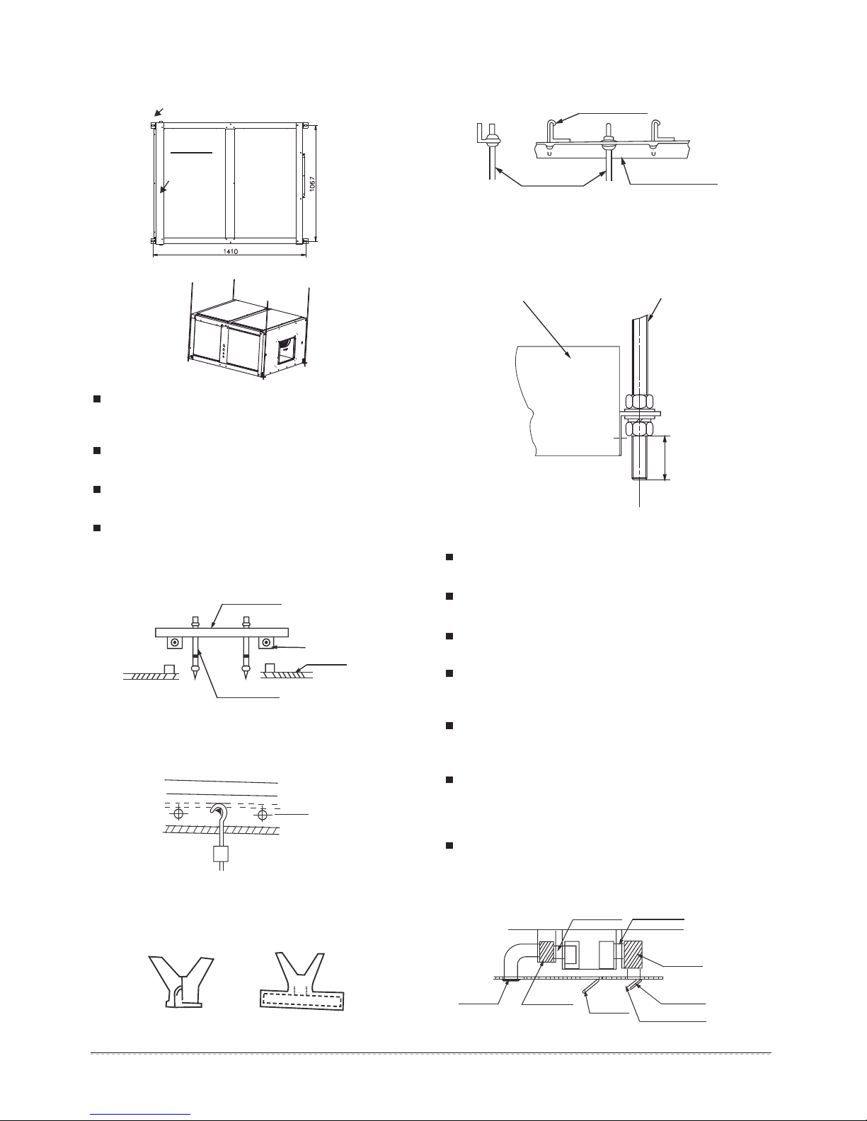
3.2 Install ĭ10 or bigger Pendant Bolts Or
Ground Bolts
Pendant bolt hole
4-12×2 5
D. Steel beam and girder structure
Set and use supportive angle steel.
Suspended bolt
Air inlet side
Fig.3-3
MVA-90CWN1-V MVA-120CWN1-V (Unit:mm)
Fig.3-4
Use ĭ10 or bigger screws. The screw material is high-quality
carbon steel (whose surface is zinc plated or undergoes other
rustproof treatment) or stainless steel.
The treatment of the ceiling varies between buildings. For
detailed measures, consult with the fitting-out staff.
Fix the pendant bolts firmly and reliably in light of the specific
situation.
Installation of the pendant bolt in different environments.
A. Wooden structure
Put rectanglar sticks across the beams, and set pendant bolts.
Wooden span
Pendant bolt
Beam
Ceiling
Fig.3-5
B. New concrete roughcast
Use embedded bolts, embedded pulling plugs, and embedded
stick harness.
Steel bar
Embedded bolt
Pipe pendant embedded bolt
Fig.3-6
C. New concrete roughcast
Set it with embedded bushes or embedded bolts.
Pendant bolt
Supportive
angle steel
Fig.3-8
3.3 Suspending The Indoor Unit
Use a hoisting device to hoist the indoor unit, align it with the
installation screw, adjust the horizontality and then tighten it.
Unit body
Pendant bolt
Not less than 30
Fig.3-9
3.4 Design And Connection Of Duct
The duct design must comply with the national heating air
conditioner pipeline design specifications.
The duct accessories and materials must be produced by
professional manufacturers.
In order to prevent air flow shorting, do not keep the air inlet pipe
near the air outlet pipe.
Install a filter at an easy-to-maintain place such as intake pipe.
(Otherwise, the duct will gather on the air heat exchanger and
lead to fault and water leak of the air conditioner.)
In order to suppress noise effectively, install noise suppression
and sound insulation devices, especially in the noise-sensitive
spaces such as meeting rooms.
For connection of the flange plane, use non-flammable canvas
adapter to prevent transmission of vibration. For its size, see the
indoor unit outline diagram. Use M6X20 screws (configured on
site) for connection.
All pipelines must be connected closely and soundly without
leak of air. The pipelines must be adiabatic and free from
condensation.
Key points of duct connection
Canvas adapter
Canvas adapter
Blade plug-in unit
Slide plug-in unit
Fig.3-7
Air outlet
Noise
suppression chamber
orifice
Inspection
Noise suppression chamber
Air inlet
Air filter
Fig.3-10
Installation Manual
3
3.5 Install the condensate drainpipe
1. Install the indoor unit drainpipe
Two drain couplings are provided on alll models.select either one
for condensate outlet and plug the other.
consult local codes or ordinances for specific requirement regarding
condensate drain.
condensate drain is open to atmosphere and must be trapped. trap
must be at least 3 inches deep and made of flexible material or
fabricated to prevent freeze-up.
if air handler is installed in a non-conditioned space,it is
recommended an auxillary drain pan be fabricated and installed
under entire unit.
Do not reduce the drain line size from the connection size provided
on the unit.
Install a drain stream trap in the drainpipe to prevent water from
overflowing. (The drainpipe absorbs the odor. When the outside
static pressure is high (especially the air inlet),it is difficult to drain
the water.)
Drainage should be natural. When constructing, the outside pipe of
outdoor unit should be inclined (1/50~1/100).
The bending part of drainpipe should be fewer than 2. Furthermore,
to reduce the depositing dust, avoid bending the pipe as possible as
you can.
Make sure there is no dust or rubbish falling into indoor unit drain
elbow and drainpipe.
After installation, remove the checking panel, pour some water in the
drain elbow to see whether it drains smoothly.
Checking panel
Drain pipe
Checking panel
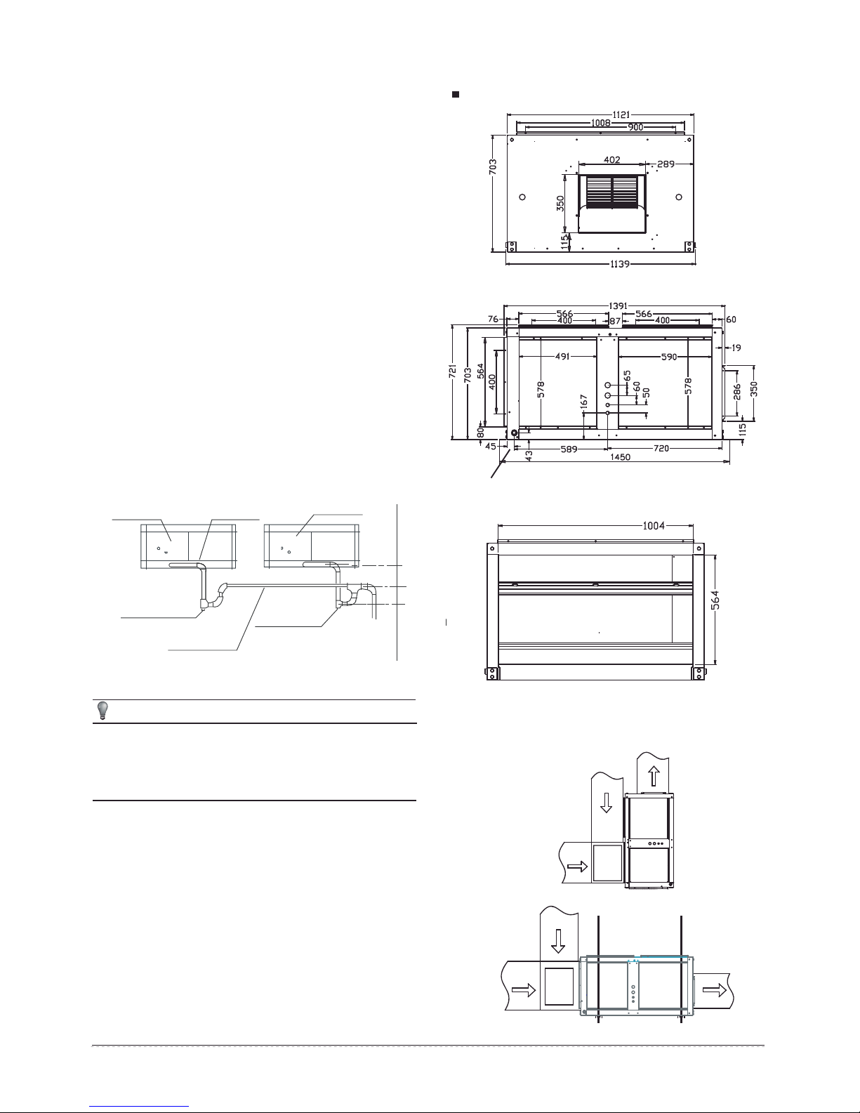
3.6 Dimension˄Unit:mm˅
MVA-90CWN1-V MVA-120CWN1-V
Front view (Air supply outlet)
3/4”NPT FEMALE
Side view (Pipes)
Fig.3-12
Fig.3-13
100mm or more
Sheath
(Checking orifice˅
General drain pipe
Sheath
(Checking orifice)
e
50mm or mor
Fig.3-11
CAUTION
Rubbish is easy to accumulate at drain stream trap. Make sure
to install a plug or other things which is easy to clean.
Unit must be slightly inclined toward drain,
Use drain connection size or larger,
Do not operate unit without trap
2. Test draining
Open the clapboard of indoor unit, pour the water in to see whether it
drain smoothly and whether there is water leakage.
3. Heat insulation
After confirming that drainage is smoothly and there is no leakage,
wrap the drainpipe with insulation material, or there will be
condensed water.
Rear view (Air return vent)
Fig.3-14
3.7 Field Installed Mixing Box Accessory
2876,'($,5
5(7851$,5
0,;,1*%2;
2876,'($,5
5(7851$,5
0,;,1*%2;
6833/<$,5
Fig.3-15
6833/<$,5
Installation Manual
4
Fig.3-16
 Loading...