

Drucegrove DragonFly TFT20 Series, DragonFly TFT022, DragonFly TFT500, DragonFly TFT024, Firefly TFT300 Series User Manual
...
User Manual
Document Version 1.4
23/11/2015

Drucegrove DragonFly User Manual 1.4 Page 2
Contents
Introduction ........................................................................................................................................................ 5
Drucegrove TFT Feature Comparison .................................................................................................................... 8
DragonFly Driver Hardware and Operating System ............................................................................................... 9
DragonFly Display Settings ................................................................................................................................... 9
DragonFly Core Software and Configuration ....................................................................................................... 10
DragonFly Boot Sequence .................................................................................................................................. 10
Micro SD Card .................................................................................................................................................... 11
DragonFly System Installation ............................................................................................................................ 12
Connecting to a Single Elevator .................................................................................................................................. 12
Connecting to Multiple Elevators ............................................................................................................................... 14
RS485 Network ........................................................................................................................................................... 15
Ethernet Network ....................................................................................................................................................... 16
DFX Layout and XML Configuration Files ............................................................................................................. 18
DFX Files ...................................................................................................................................................................... 18
XML Files ..................................................................................................................................................................... 18
Manually Creating and Editing XML Files .................................................................................................................... 19
Settings XML File ................................................................................................................................................ 21
Indicator Settings ........................................................................................................................................................ 21
Network Settings ......................................................................................................................................................... 23
Date and Time Settings ............................................................................................................................................... 23
Video Settings ............................................................................................................................................................. 24
Identity XML File ................................................................................................................................................ 25
Identity Settings .......................................................................................................................................................... 25
Network Settings ......................................................................................................................................................... 25
Groups ......................................................................................................................................................................... 26
DragonFly Designer Software ............................................................................................................................. 27
DragonFly Layouts (DFX Files) ............................................................................................................................. 28
Static Background Image Layer ................................................................................................................................... 29
‘Element Canvas’ Root Element Layers ....................................................................................................................... 30
‘Dynamic Ticker Text’ Root Element ........................................................................................................................... 30
‘Video’ Root Element .................................................................................................................................................. 30
Dynamic Sub Elements ................................................................................................................................................ 31
Element Conditions ..................................................................................................................................................... 32
Video Element ................................................................................................................................................... 35
Supported Video Formats ........................................................................................................................................... 37
Supported Audio Formats for Video ........................................................................................................................... 38
Supported Containers for Video ................................................................................................................................. 38
Supported Network Protocols for Video..................................................................................................................... 39
Live Network Video Overview ................................................................................................................................. 39
Configuring the DragonFly for Live Network Video ................................................................................................ 40
DragonFly Variables ........................................................................................................................................... 41

Drucegrove DragonFly User Manual 1.4 Page 3
Live Data Feeds .................................................................................................................................................. 45
RSS (XML) Feeds .......................................................................................................................................................... 45
Text Feeds ................................................................................................................................................................... 45
Parser Arguments ....................................................................................................................................................... 47
Variables...................................................................................................................................................................... 47
Source URL .................................................................................................................................................................. 49
Read Actions ............................................................................................................................................................... 49
XML Read Actions ....................................................................................................................................................... 50
Text Read Actions........................................................................................................................................................ 51
Using the DragonFly Designer ............................................................................................................................. 52
Tutorial 1: Opening and Editing a Template Layout ................................................................................................... 52
Tutorial 2: Previewing the Layout ............................................................................................................................... 56
Tutorial 3: Creating an SD Card ................................................................................................................................... 59
Tutorial 4: Creating an Automatic Update USB Drive ................................................................................................. 61
Tutorial 5: Broadcasting a Layout over a LAN ............................................................................................................. 62
Tutorial 6: Creating a New Layout .............................................................................................................................. 63
Tutorial 7: Setting a Background Image ...................................................................................................................... 68
Tutorial 8: Drawing on the Background Layer ............................................................................................................ 70
Tutorial 9: Adding and Configuring Screen Elements ................................................................................................. 74
Tutorial 10: Adding a Dynamic Text Element .............................................................................................................. 77
Tutorial 11: Configuring a Dynamic Text Element to update based on Conditions .................................................... 80
Tutorial 12: Configuring a Dynamic Text Element to act as a timed Text Slideshow ................................................. 84
Tutorial 13: Adding a Dynamic Image Element that updates based on Conditions ................................................... 88
Tutorial 14: Adding Weather Elements ....................................................................................................................... 95
Tutorial 15: Animating Elements based on Conditions ............................................................................................. 104
Tutorial 16: Adding a Video Element ........................................................................................................................ 110
Message Library ............................................................................................................................................... 116

Drucegrove DragonFly User Manual 1.4 Page 4
Important Note
This document is a work in progress, and may not fully explain all aspects of the DragonFly
hardware or software. For any technical questions that are not addressed in this manual, please
contact Drucegrove directly:
Email: technicalsupport@drucegrove.com
Phone: +44 (0)1992 650 486 (Select Option 3)
This document explains the basics of the DragonFly hardware, how the DragonFly core software
operates, and describes how the DragonFly can be set up and configured using the DragonFly
Designer software.
Drucegrove DragonFly User Manual 1.4 Page 5
Introduction
The Drucegrove DragonFly™ range of TFT displays are capable of showing elevator position, direction and emergency
messages in addition to other text, images and rich media. This allows the displays to be branded and customised
match the building they are installed in. The additional text and images can be static (ie building name, company
logo, etc), or dynamic based on the position of the elevator (ie individual floor tenancy information).
The TFT20 Series displays are self contained units with the display and driving electronics integrated into one
package. The screen sizes available are 4.3”, 5.7” and 7.0”, and they have the same built in message image library as
the FireFly™ TFT300 Series indicators.
For larger DragonFly™ displays, the TFT500 Omni Driver can be used. This is based on the same driving electronics as
the TFT20 series but boasts a more powerful processor with graphics accelerating and video decoding hardware, and
a DVI / HDMI output. Drucegrove supply a separate open frame TFT screen and a HDMI to DVI cable for connecting
the screen to the TFT500 Omni Driver. The screen sizes available range from 10.4” to 42”, in 4:3 standard, 16:9 wide
or 4:1 panoramic aspect ratios
The TFT20 Series and TFT500 can be networked via Ethernet, which opens up the possibility of streaming live news
headlines, weather, finance information, transport information (TfL, Nation Rail, bus times etc) and more from RSS
feeds.
Live video can also be displayed on displays driven from the TFT500 Omni Driver. The video is streamed digitally to
the display over Ethernet from either an IPTV source or an IP CCTV camera - either of which can be located anywhere
in the building. Being digital, a single video feed can be streamed to an unlimited number of displays without loss of
quality or the need for boosters or amplifiers.
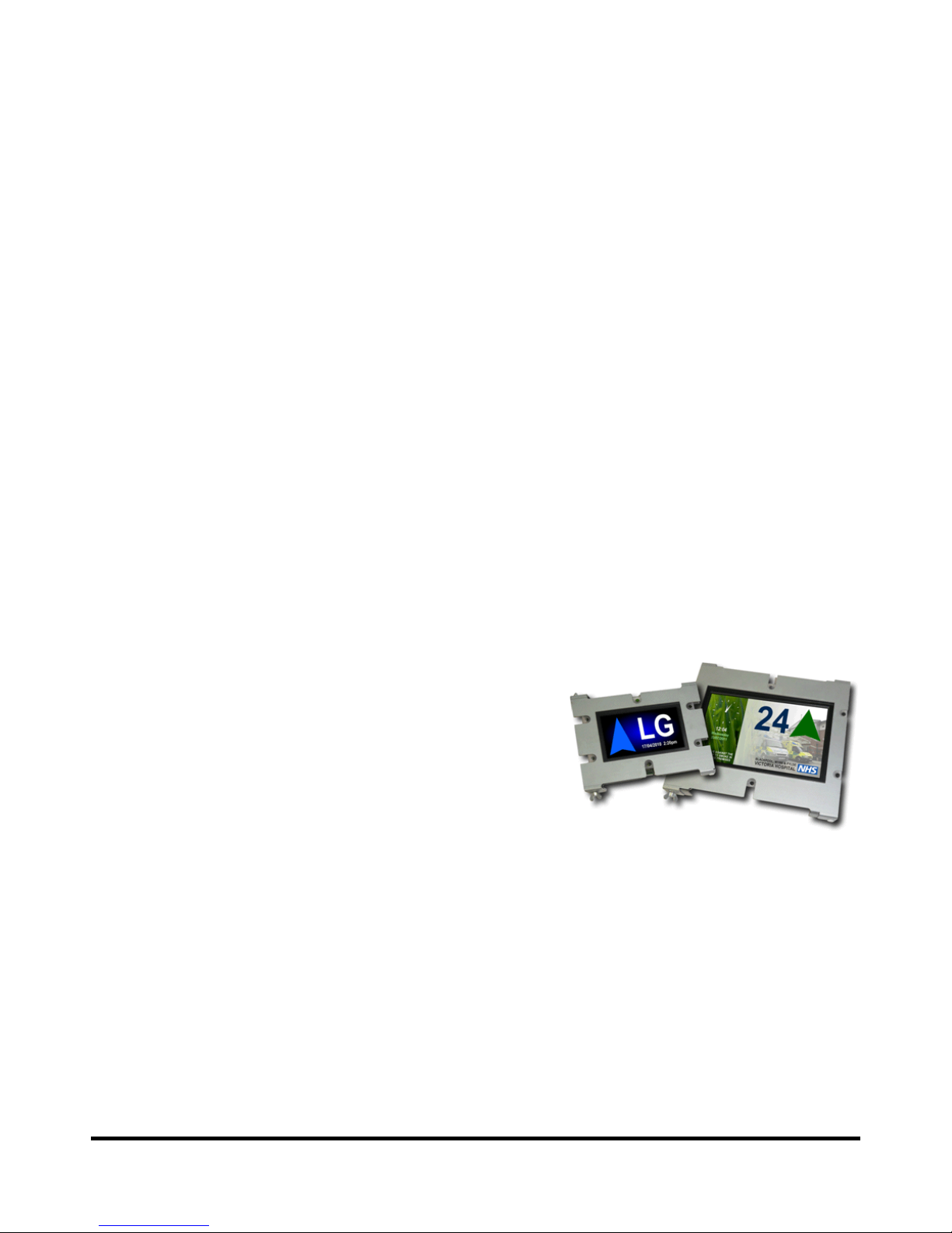
DragonFly TFT20 Series TFT Position Indicators
Drucegrove’s DragonFly™ TFT20 Series Indicators are available in
three standard sizes: 4.3", 5.7" and 7.0". The displays are fully
customisable, and at their simplest level offer a wide choice of
colours, images, character fonts and arrow styles. They are available
with a choice of two different integrated drivers, the RE1 or the RE2.
The RE1 offers basic drawing options with no animation or video. The
RE2 has hardware accelerated graphics allowing smooth animation,
alpha blending and live video playback.
The position indicators may be configured for elevator car or landing displays, and are capable of showing up to
three character floor designations, car direction arrows, hall lantern arrows, full screen messages and pictograms.
They are fully compatible with the Drucegrove 2-Wire™ System and OTIS® Serial Data, and may also be used as
stand-alone position indicators with binary, Gray or discrete wire-per-floor inputs.
Every aspect of the display can be configured, and special display content can be configured to show or change at
certain floors, for certain message responses, or even for a specific time of day or date.
The position indicators can be configured over a LAN via a standard web browser, or alternatively the on-board
micro SD card can be removed and reconfigured freely from any computer.
Drucegrove DragonFly User Manual 1.4 Page 6
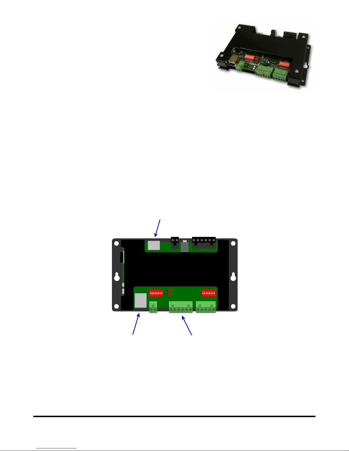
DragonFly TFT500 TFT Screen Driver
The DragonFly™ TFT500 Omni Driver works with any readily available
DVI or HDMI display, so if our standard range of sizes is not enough,
choose another! For interfacing to your elevator, the Omni Driver
connects to either the Drucegrove 2-Wire™ System, OTIS ® Serial Data,
or with the addition of an IND059 input mode, non-proprietary binary /
Gray / discrete signals. The unit can be networked via RS485 and
Ethernet for live data feeds and live network video streams.
Take advantage of their most sophisticated features. Use the latest technology in processing graphics to combine
elevator information with scrolling text feeds, rich media and video content. Our in-house team will take your
concept, images and logos to produce a result that suits your building. And with the open connectivity that we have
provided you will never be out of date.
We can supply any size of open-frame TFT display, with a lens and any mountings and faceplates needed for fitting
inside your elevator cars, and all necessary networking peripherals for connecting together a system of displays.
Our in-house metalwork facilities allow us to mount any display in almost any location with a professional finish and
minimal hassle.
For basic operation, the TFT500 simply needs a 2-Wire input for power and elevator data, and a screen connected to
the HDMI / DVI output. For data synchronisation and live data or video feeds, the Ethernet Network would need to
be connected:
TFT500
2-Wire Supply Input
Two pairs of + and - terminals are
present for Loop In / Loop Out
2-Wire connectivity
Ethernet Network
HDMI / DVI Output
Connect HDMI-to-DVI cable
Drucegrove DragonFly User Manual 1.4 Page 7
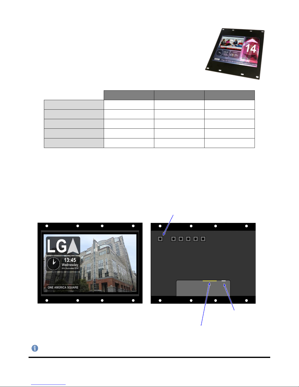
DragonFly Open Frame TFT Screens for use with the TFT500 Screen Driver
Drucegrove offer a standard range of three open frame industrial grade TFT
displays to run from the TFT500 Omni Driver - a 10.4”, 15” or 19” screen with
suitable mountings and either toughened glass or polycarbonate protection.
The screens have a DVI or HDMI input, allowing them to be driven directly from
the TFT500 output.
The standard three screen sizes have the following technical specifications:
10.4”
15”
19”
Resolution (pixels)
1024 × 768
1024 × 768
1280 × 1024
Luminance (cd/m2)
500
350
600
Contrast Ratio
1200:1
1000:1
2000:1
Viewing Angle
88 / 88 / 88 / 88
85 / 85 / 85 / 85
89 / 89 / 89 / 89
Backlight Half Life
50000 Hours
50000 Hours
50000 Hours
A wide range of other non-standard screen sizes are also available in an open frame mounting with a HDMI or DVI
input, ranging from 7” to 70” in diagonal size and in 4:3 standard, 16:9 wide or 4:1 panoramic aspect ratio. Refer to
screen specific documentation or contact Drucegrove for more information.
Note: External TFT screens require their own power supply, and are not powered from the 2-Wire bus.
DVI Input
Connect HDMI-to-DVI cable
Display Power Supply
from local 12V 4A DC PSU
Screen Power Button
The state of this button is remembered
after power down, and this button leaves
the factory in the ’on’ state, so it should
not need to be pushed again
Drucegrove DragonFly User Manual 1.4 Page 8
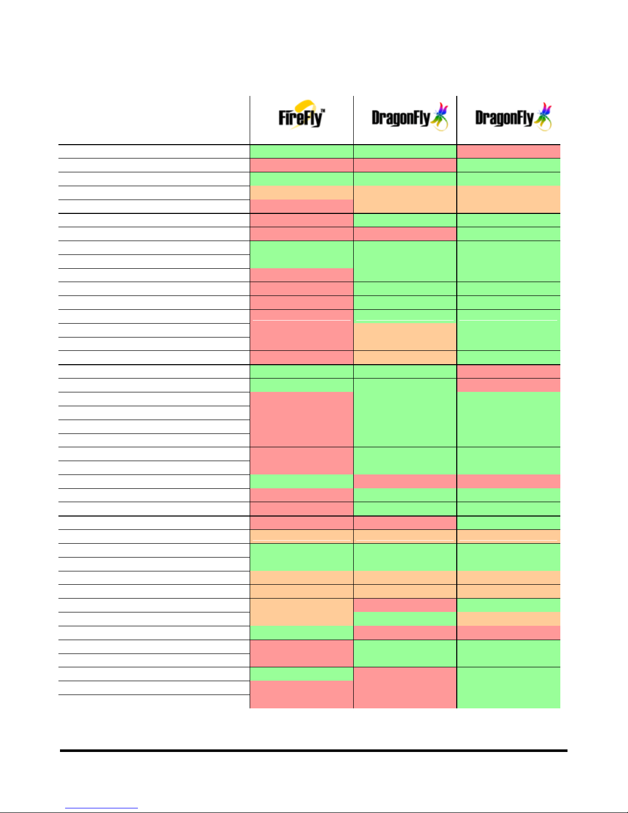
Drucegrove TFT Feature Comparison
The following comparison table shows the feature differences between the TFT300 series FireFly, TFT20 Series
DragonFly and the TFT500 DragonFly Omni Driver:
TFT300 Series (4.3”, 5.7” & 7.0”)
TFT20 Series (4.3”, 5.7” & 7.0”)
TFT500 Omni Driver (from 10.4”)
Integrated TFT display (4.3”, 5.7” or 7.0”)
Yes
Yes
No
DVI / HDMI output for external TFT display (10.4” to 42”)
No
No
Yes
Drucegrove 2-Wire™ input compatible
Yes
Yes
Yes
OTIS® Serial Data input compatible
Yes (at additional cost)
Yes (at additional cost)
Yes (at additional cost)
Stand Alone (binary/Gray/discrete) input compatible
No
Yes (with addition of IND59)
Yes (with addition of IND59)
Ethernet network connectivity (wired)
No
Yes
Yes
RS485 network connectivity
No
No
Yes
Display elevator position and direction
Yes
Yes
Yes
Display elevator status and emergency messages
Yes
Yes
Yes
Display elevator floor tenancy information per floor
No
Yes
Yes
Display time and / or date
No
Yes
Yes
Display static text, logos and images
No
Yes
Yes
Display live RSS feeds (eg news, weather, TfL, etc)
No
Yes
Yes
Display Video from local file on micro SD card
No
Yes (RE2 version only)
Yes
Display Video from remote live network source (IPTV)
No
Yes (RE2 version only)
Yes
Display Video from remote network camera (IP CCTV)
No
Yes (RE2 version only)
Yes
Built in library of over 150 full screen elevator message images
Yes
Yes
No
Standard range of themes available to choose from
Yes
Yes
No
Background can be configured as any colour or image
No
Yes
Yes
Text and arrows can be configured as any colour
No
Yes
Yes
Text can be configured as any font
No
Yes
Yes
Arrows can be configured as any shape
No
Yes
Yes
Screen elements can be shown / hidden on elevator events
No
Yes
Yes
Screen elements can be shown / hidden at specific times / dates
No
Yes
Yes
Display options configured via dipswitches
Yes
No
No
Display options stored in XML files on micro SD card
No
Yes
Yes
Display options can be remotely changed via network
No
Yes
Yes
Built in audio amplifier for speech and/or video audio
No
No
Yes
Built in gong
Yes (at additional cost)
Yes (with addition of GNG24)
Yes (with addition of GNG24)
Supplied with purpose designed mountings
Yes
Yes
Yes
Supplied with lens
Yes
Yes
Yes
Supplied with faceplate
Yes (at additional cost)
Yes (at additional cost)
Yes (at additional cost)
Supplied in surface mount fixture
Yes (at additional cost)
Yes (at additional cost)
Yes (at additional cost)
Low Profile, with option of remote TFT display
Yes (at additional cost)
No
Yes
Vandal Resistant to EN81-71 Category 2
Yes (at additional cost)
Yes
Yes (at additional cost)
Meets elevated temperature requirement of EN81-72
Yes
No
No
Runs on Windows CE operating system
No
Yes
Yes
Battery backed, network synchronisable real time clock
No
Yes
Yes
2 discrete outputs for driving external LED arrows
Yes
No
Yes
2 addition general purpose outputs
No
No
Yes
4 general purpose inputs for triggering screen events
No
No
Yes

Drucegrove DragonFly User Manual 1.4 Page 9
DragonFly Driver Hardware and Operating System
The DragonFly hardware is based around an ARM Cortex processor, and runs the Microsoft Windows CE 6.0
operating system. The hardware and operating system were specifically designed for embedded industrial
applications. There are no mechanical drives – all storage is flash based. The hardware does not require active
cooling, and is not damaged by power loss or cycling – even if the boot sequence is interrupted. If power is lost and
restored, the DragonFly will automatically reboot and recover without issue.
Internally, the DragonFly has a non-volatile flash drive which contains basic boot loader software. This boot loader
runs the main DragonFly software automatically on power up. The main DragonFly software and all relevant layout
and configuration files are stored on a removable micro SD card (refer to individual product wiring diagrams for
micro SD card location).
The TFT20 series DragonFly driving hardware can either be built around the RE1 or the RE2 engine. The RE1 offers
basic drawing options with no animation or video. The RE2 has hardware accelerated graphics allowing smooth
animation, alpha blending and live video playback.
There are no engine options with the TFT500, and hardware accelerated graphics is available in this unit by default.
DragonFly Display Settings
The TFT022, TFT023 and TFT024 have an integrated screen with the following resolutions
TFT022 has a 4.3” screen with a resolution of 480×272 pixels
TFT023 has a 5.7” screen with a resolution of 640×480 pixels
TFT024 has a 7.0” screen with a resolution of 800×480 pixels
The TFT500 Omni Driver can be configured to output any resolution on its DVI output. The resolutions of the
standard screen sizes are as follows:
10.4” screen has a resolution of 1024×768 pixels
15” screen also has a resolution of 1024×768 pixels
19” screen has a resolution of 1280×1024 pixels
Note: All DragonFly screens are driven at 16 bit colour depth (RGB 5-6-5) by default.

Drucegrove DragonFly User Manual 1.4 Page 10
DragonFly Core Software and Configuration
All software configuration, fonts, images, data files, etc are stored on the micro SD card:
The core software itself is stored under the “\Storage Card\Bin\” directory.
All of the software and layout settings are stored in XML files under the “\Storage Card\Config\” directory.
Layouts are stored in DFX files under the “\Storage Card\Config\Theme\” directory.
Other data is stored under “\Storage Card\Data\”. This includes fonts, and the message image library files.
The software and configuration are automatically set up on the micro SD card by the DragonFly Designer software.
The same DragonFly core software works on all TFT20 Series and TFT500 hardware, regardless of the processor
engine or screen type.
DragonFly Boot Sequence
The RE1 based DragonFly has no internal flash, so its boot sequence is as follows:
1. A registry key is present to automatically run “\SD Card\Startup\Startup.exe”
2. Startup.exe sets up the desktop environment, installs any default fonts, configures the Ethernet network,
initialises the data receiver firmware, and finally runs “\SD Card\Bin\DragonFly.exe”
3. DragonFly.exe shows a white splash screen with a DragonFly logo as it loads, before finally displaying the
screen layout selected in the Settings.xml file.
If the Startup.exe software does not automatically run after creating a new SD card, it will need to be manually run
the for the first time using a USB mouse/keyboard and the Windows CE file explorer. Double click on Device,
followed by SD Card and then Startup. Then double click on Startup.exe. The software will automatically create the
auto-run registry key for the next time the device boots up.
The RE2 and RM2 based DragonFly has the Startup.exe software pre-installed in internal flash, so its boot sequence
is as follows:
1. Startup.exe is run from the internal flash, and installs any default fonts, configures the Ethernet network,
initialises the data receiver firmware, and finally runs “\Storage Card\Bin\DragonFly.exe”
2. DragonFly.exe shows a white splash screen with a DragonFly logo as it loads, before finally displaying the
screen layout selected in the Settings.xml file.
As a failsafe, The Windows CE image on the RE2 and RM2 will also launch “\Storage Card\Startup\Startup.exe”
automatically. This instance of the software will check the internal flash instance and replace it if it is not fully
present or has not executed in a timely manner.
If there is no micro SD card inserted, the Startup.exe software on the internal flash will not find “\Storage
Card\Bin\DragonFly.exe”, and will show an error message on the screen. The unit will then automatically reboot
itself after 2 minutes.
Drucegrove DragonFly User Manual 1.4 Page 11
Micro SD Card
The micro SD card must be present at all times in order for the DragonFly to operate. If the micro SD card is ever
changed, then it is recommended that the DragonFly be rebooted.
The micro SD card must be formatted to FAT, and the maximum capacity is 4GB. Note that SDHC and SDXC micro SD
cards are not supported.
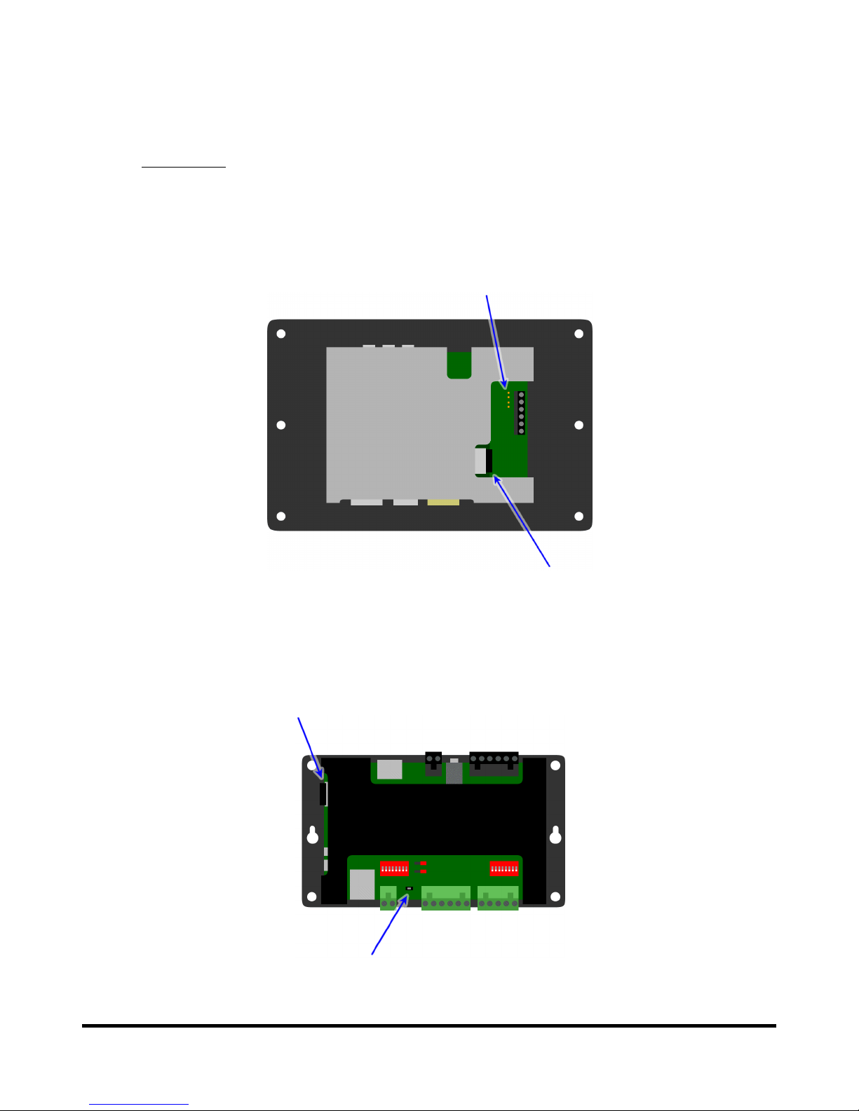
On the TFT20 Series the micro SD card socket is on the smaller PCB raised off the main PCB (there is a cut out in the
back plate to access the socket), and there is a pair of reset pins between behind the input terminals. The reset pins
are labelled RST, and should be shorted to each other to perform a reboot:
On the TFT500 the micro SD card socket is on the side, and there is a reset button between the RS485 terminal and
the input terminals, which should be pressed to perform a reboot:
Reset Button
micro SD Card
Reset Pins (RST)
micro SD Card
Drucegrove DragonFly User Manual 1.4 Page 12
DragonFly System Installation
Connecting to a Single Elevator
For the most basic operation of displaying the elevator car position and direction, a DragonFly only needs to be
connected to a Drucegrove 2-Wire bus. The 2-Wire bus will provide both power and data to the DragonFly driving
circuitry. For a TFT20 series position indicator, this 2-Wire bus will also power the TFT screen. For the TFT500 Omni
Driver, a separate external screen will be provided and this will have a 12V DC power supply which will need mains
110-230V AC input.
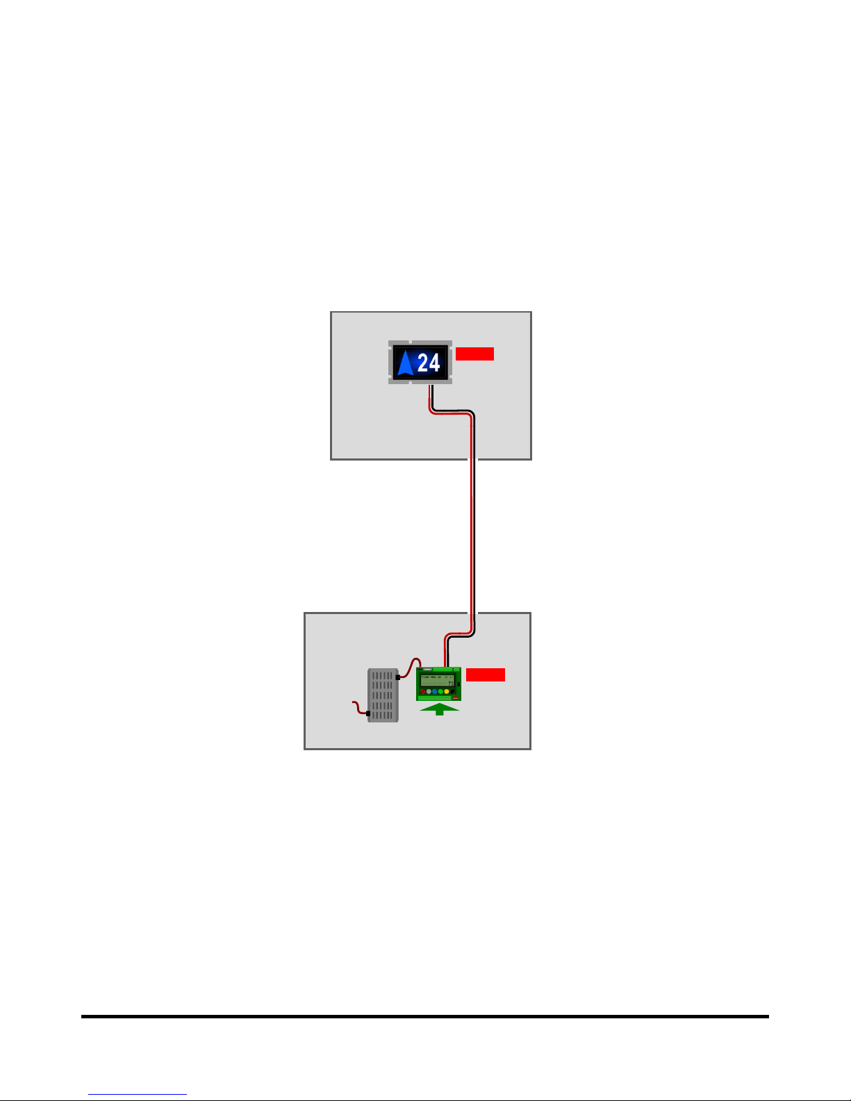
The following diagram shows how a TFT024 positioned inside the elevator car should be connected back to a
Drucegrove IND055 2-Wire controller:
Additional 2-Wire equipment may be connected to the 2-Wire bus, including other FireFly and DragonFly TFTs (of
mixed sizes), LED segment and dot matrix PIs, gongs and speech announcer units.
Elevator Car
TFT024
DragonFly
7.0” TFT PI
Machine Room
110-230V
AC Input
}
Inputs from
Elevator Controller
2 Wires for
Power and Data
IND055
Controller
Interface
24V DC
PSU
Drucegrove DragonFly User Manual 1.4 Page 13
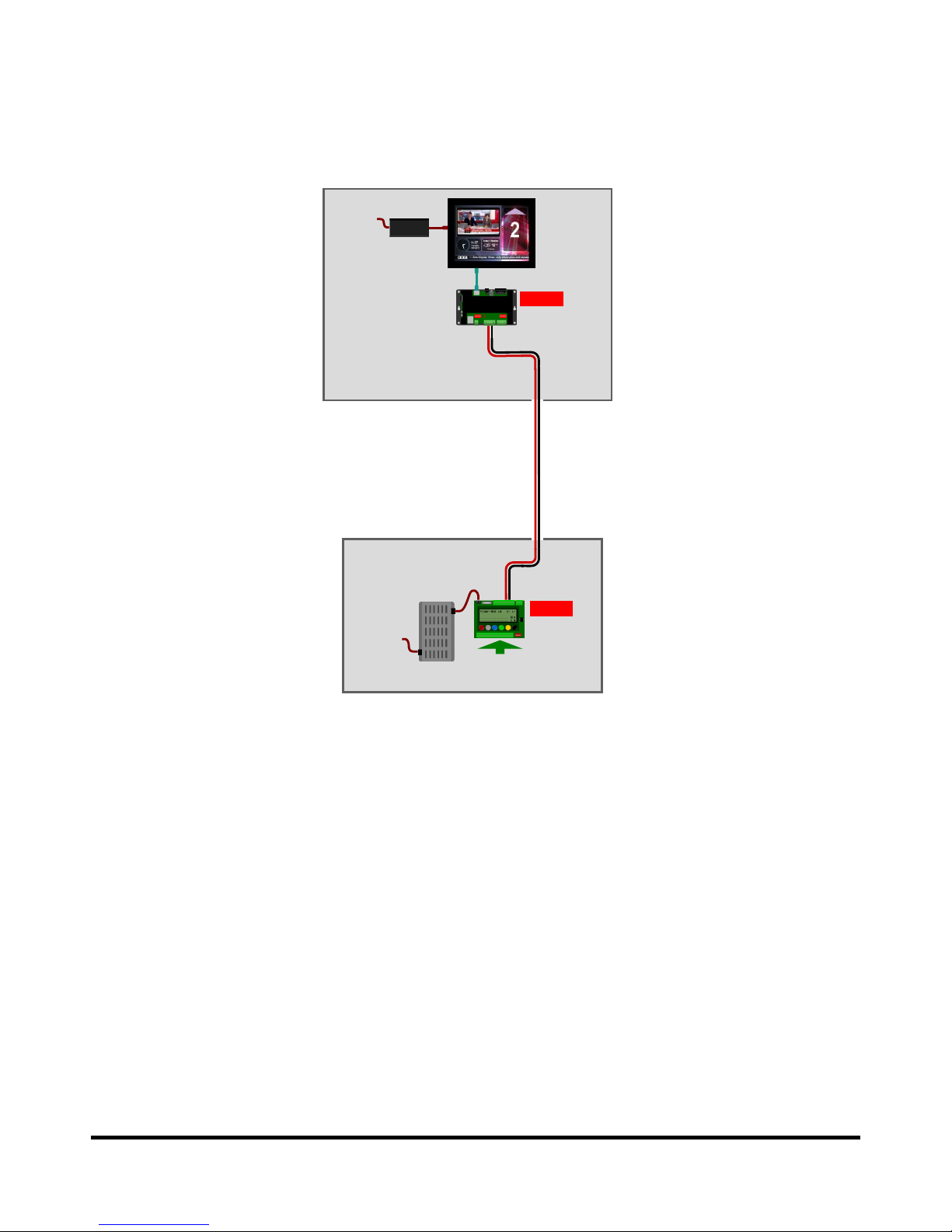
The following diagram shows how a TFT500 with an external TFT screen positioned inside the elevator car should be
connected back to a Drucegrove IND055 2-Wire controller.
Note that a local 12V DC power supply requires a 110-230V AC input inside the elevator car:
12V DC
PSU
TFT Screen
with DVI Input
TFT500
DragonFly
Omni Driver
110-230V
AC Input
Machine Room
110-230V
AC Input
}
Inputs from
Elevator Controller
2 Wires for
Power and Data
IND055
Controller
Interface
24V DC
PSU
Elevator Car
Drucegrove DragonFly User Manual 1.4 Page 14
Connecting to Multiple Elevators
It is possible to connect the TFT500 to the 2-Wire bus of multiple elevators. This is done using IND079 2-Wire to
RS485 transcoders. The IND079s each take in a single 2-Wire feed, and communicate back to single TFT500 via an
RS485 network.
It is possible to have up to 63 IND079s on an RS485 network back to a single TFT500. The DragonFly Designer
software can be used to configure screen elements to look at specific elevator position and status data on the RS485
bus rather than the local 2-Wire input on the DragonFly itself.
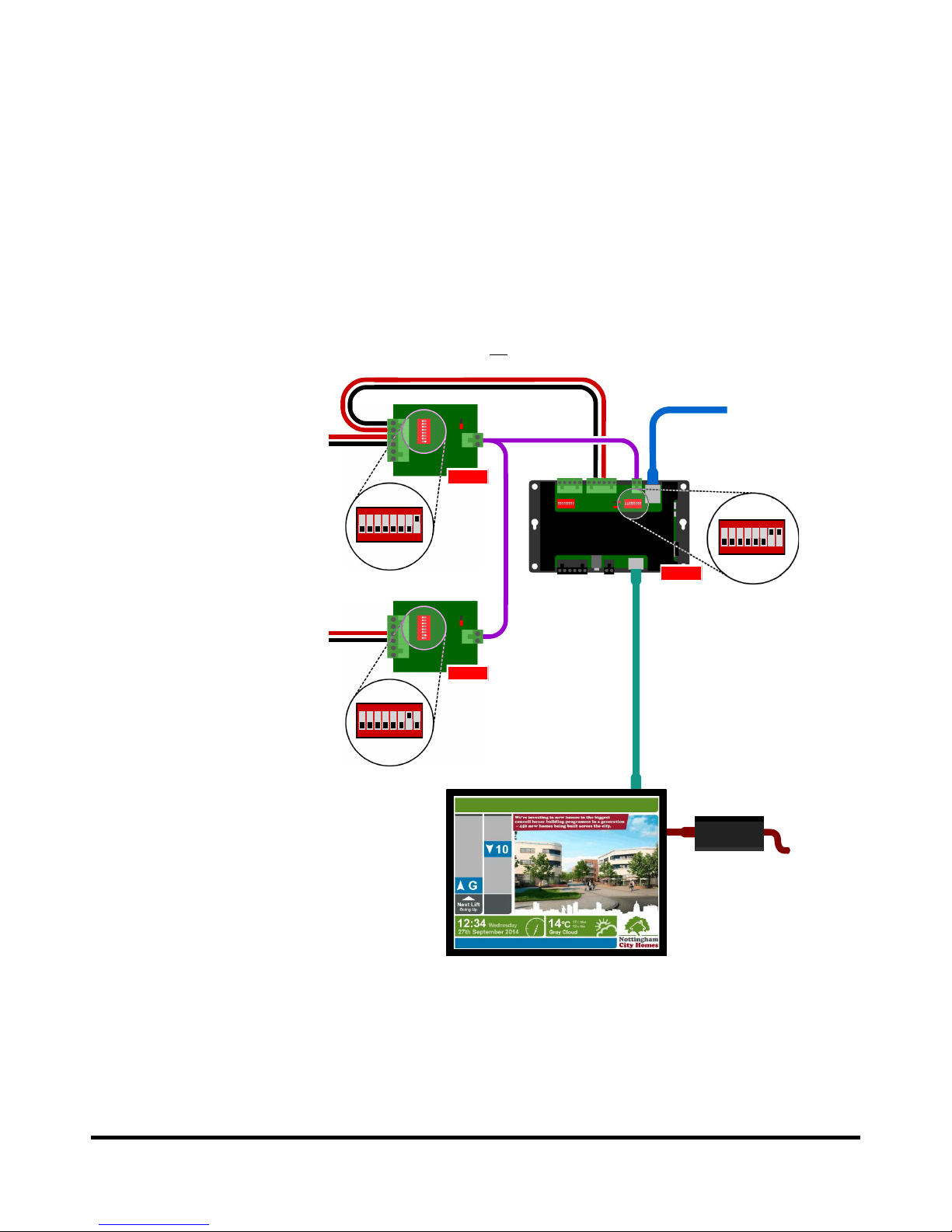
The following diagram shows how two elevators in a duplex could be connected to a single TFT500 to show the
position and status of each elevator car on one screen:
For more elevators, additional IND079s would be required (up to a maximum of 63 units), and their RS485 networks
would be “daisy chained” together. The maximum transmission distance of the RS485 is 4000 feet, but it is
recommended that all IND079s be kept local to the TFT500, and any long distance runs be on the 2-Wire bus.
ON
110-230V AC
Mains Input
24V DC
Power
Supply
DVI to HDMI
UTP
IND079
2-Wire Supply (Left) Loop In/Out
Provides both power and elevator data
Connect IND055 output from left elevator
and ensure that the address is set to 1
(dipswitch 8 on only)
2-Wire Supply (Right) Loop In/Out
Provides both power and elevator data
Connect IND055 output from right elevator
and ensure that the address is set to 2
(dipswitch 7 on only)
TFT500
CAT5
Ethernet Connection
to network for live data
feeds and time / date
synchronisation
ON
ON
IND079
2-Wire supply looped from one IND079 input to
TFT500 input, to provide TFT500 with power
Ensure that the network address is
set to 3 (dipswitches 7 and 8 on),
and the adjacent RS485 Master
jumper is set to the ON position

Drucegrove DragonFly User Manual 1.4 Page 15
RS485 Network
The TFT500 Omni Driver has an on board RS485 port. This can currently be used for multi-elevator based TFT
displays using a network of IND079 transcoders.
The RS485 network should be connected together in a “daisy chain” using unscreened twisted pair.
All units on the RS485 network should have a unique network address, which is selected via the on board Network
Address dipswitch on the TFT500 and IND079. The network address is linked to the least significant byte of the IP
address of a TFT500 by default (this can be changed in the DragonFly settings).
There needs to be one TFT500 on the RS485 network acting as an RS485 master. This master mode function can be
selected via a jumper next to the Network Address dipswitch.
Note: The RS485 wires are polarised so should be connected to each terminal block in the same orientation.
Note: All RS485 wiring needs to be twisted pair. If there are untwisted sections, the network will not work.
Drucegrove DragonFly User Manual 1.4 Page 16
Ethernet Network
The Ethernet Network can be used to connect one or more DragonFly units back to a PC / Laptop for remote
simultaneous configuration, real time clock synchronisation, live data feeds from Ethernet based sensors or internet
based RSS feeds, and live multicast IPTV based video or an IP camera feed.
The Ethernet network uses standard IP based protocols, and so standard CAT5 cabling and Ethernet switches may be
used. For certain features, managed Ethernet switches are recommended, and may need to be specially configured
for IGMP traffic (see information on the Video Canvas for more information, or contact Drucegrove directly).
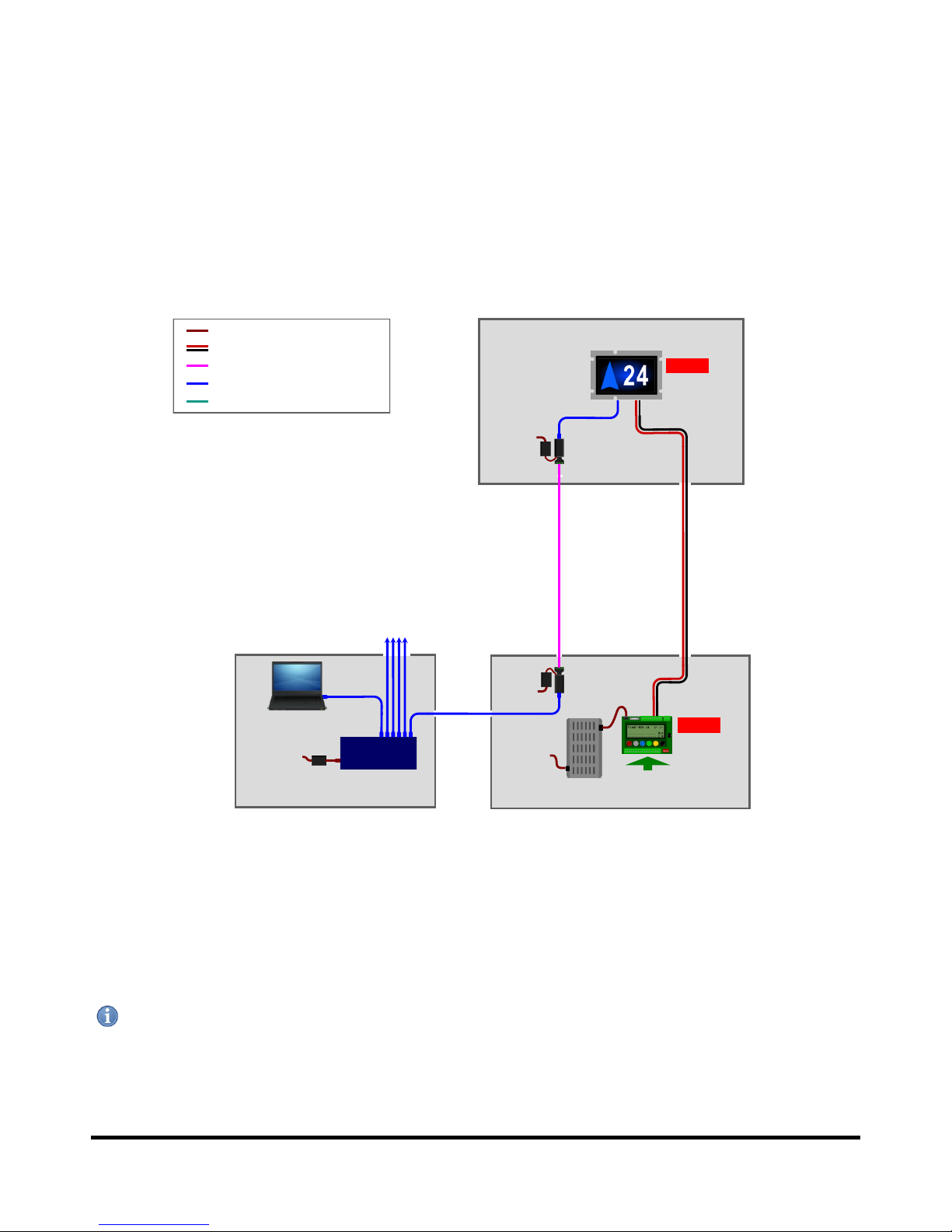
The following diagram shows how a TFT024 should be networked from an elevator car back via a machine room to a
central building management room:
Note that the maximum distance of an Ethernet run is 100 meters (328 feet), and if the trailer run from the TFT
screen back to an Ethernet switch is over this distance, Ethernet Extenders need to be used (as shown in the above
diagram). If the distance is less than 300 feet, a CAT5 trailer may be used without Ethernet Extenders.
Note: All Ethernet wiring needs to be twisted pair. If there are untwisted sections, the network will not work.
Elevator Car
TFT024
DragonFly
7.0” TFT PI
Machine Room
110-230V
AC Input
}
Inputs from
Elevator Controller
2 Wires for
Power and Data
IND055
Controller
Interface
24V DC
PSU
110-230V
AC Input
110-230V
AC Input
Ethernet
Extender
4 × UTP on Trailer
Max length 300 feet, or 2500 feet if
Ethernet Extenders are used
CAT5
Building Management Room
CAT5 Ethernet connections
to other machine rooms
CAT5
Ethernet
Extender
110-230V
AC Input
Ethernet
Switch
PC / Laptop
Unscreened Twisted Pair for network
2× AWG14 cables for 24V power and data
CAT5 for network (max length 300 feet)
HDMI (HDCP encryption not supported)
110V - 230V Mains power cable
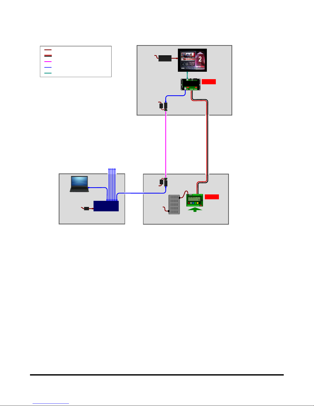
Drucegrove DragonFly User Manual 1.4 Page 17
The following diagram shows how to network a TFT500 Omni Driver inside an elevator car:
Unscreened Twisted Pair for network
2× AWG14 cables for 24V power and data
CAT5 for network (max length 300 feet)
HDMI (HDCP encryption not supported)
110V - 230V Mains power cable
12V DC
PSU
TFT Screen
with DVI Input
TFT500
DragonFly
Omni Driver
110-230V
AC Input
Elevator Car
Machine Room
110-230V
AC Input
}
Inputs from
Elevator Controller
2 Wires for
Power and Data
IND055
Controller
Interface
24V DC
PSU
110-230V
AC Input
110-230V
AC Input
Ethernet
Extender
4 × UTP on Trailer
Max length 300 feet, or 2500 feet if
Ethernet Extenders are used
CAT5
Building Management Room
CAT5 Ethernet connections
to other machine rooms
CAT5
Ethernet
Extender
110-230V
AC Input
Ethernet
Switch
PC / Laptop

Drucegrove DragonFly User Manual 1.4 Page 18
DFX Layout and XML Configuration Files
DFX Files
The DragonFly uses a proprietary file format for its screen layouts, with the file extension *.dfx. These files can be
loaded and saved directly from the DragonFly Designer software, and will be loaded directly by the DragonFly core
software. The DFX file contains position and appearance settings for all screen elements, a full size static background
image, and any embedded images and fonts for dynamic screen elements.
XML Files
All device settings are stored in XML (Extensible Markup Language) files on the micro SD card on the DragonFly.
These files are standard text files which can be created and edited using any text editor (ie, Notepad). The DragonFly
Designer software will create all necessary XML files by default when an SD card is created. It should not be
necessary to create or modify XML files manually. There are two main XML files stored under the Config directory on
the micro SD Card:
1. Settings.xml is situated in “\Storage Card\Config\”. This file always has this name, and must be in this
location. It is not an optional file, and the software will fail to load without it. It contains top level settings,
and references the Theme DFX file and an optional Input XML file.
2. Identity.xml is situated in “\Storage Card\Config\”. This file always has this name, and must be in this
location. It is not an optional file, and the software will fail to load without it. It contains several fields for the
sole purpose of identifying the location of the DragonFly unit within a site over a LAN (site name, building
name, elevator group, elevator number, etc). The floor position address is stored in the Identity.xml file,
which is used for car/lantern behaviour. LAN settings are also stored in Identity.xml, including the DHCP
setting and manual IP address settings.
There is one further optional XML file:
3. The Input XML file is situated in “\Storage Card\Config\Input\”. Multiple data files can be stored in this
directory with different names. The Settings.xml file references the input file to use, and it is an optional file;
it is not required for the core software to function. The input file contains settings for IND21 2-Wire
compatibility (floor designation and message table), or input configuration for use with an IND059
binary/Gray/discrete input module.
Drucegrove DragonFly User Manual 1.4 Page 19
Manually Creating and Editing XML Files
Under normal circumstances, the XML files on the micro SD Card should not need to be edited. When creating a
micro SD Card from the DragonFly Designer software, the XML files will be created and configured automatically.
Updates via USB or a LAN will automatically modify relevant XML files accordingly.
Under special circumstances XML files can be created and edited using any basic text editing software. Microsoft
Notepad can be used, but the free GNU text editor Notepad++ (http://notepad-plus-plus.org) is recommended as it has
syntax highlighting for XML files.
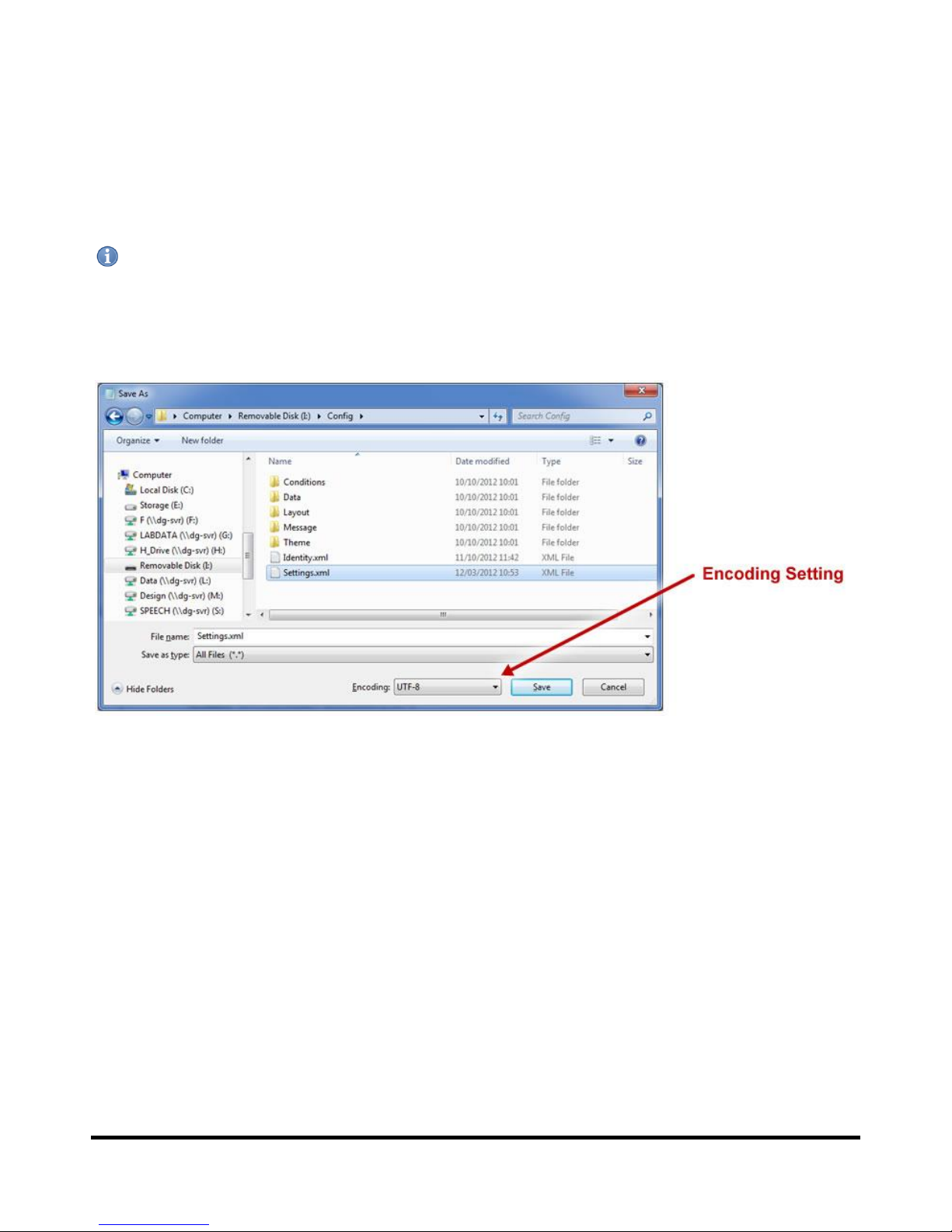
Note: XML Files should be in UTF-8 format.
If Microsoft Notepad is used, ensure that the encoding is set to UTF-8 (8 bit Unicode Transformation Format) when
the file is saved (this setting is next to the Save button on the Save As dialog). If UTF-8 is not used, the DragonFly
software will fail to load the XML file.

Drucegrove DragonFly User Manual 1.4 Page 20
The following is an example of an XML file, which has been colour coded to highlight different elements:
<?xml version="1.0" encoding="UTF-8"?>
<!-- Comment -->
<Root>
<SettingGroup>
<Setting>Value</Setting>
</SettingGroup>
<ElementGroup>
<Element> <!-- Comment -->
<Setting>Value</Setting>
</Element>
<Element AttributeName="AttributeValue">
<Setting>Value</Setting>
<Setting>Value</Setting>
</Element>
</ElementGroup>
</Root>
The first line (shown in orange) should always be present; it defines the XML version and encoding, and the
DragonFly software will not load the XML file without this.
Comments (shown in green) can be added to an XML file between <!-- and --> tags.
The XML structure consists of nodes (shown in black) and settings (shown in blue). The names of these nodes and
settings vary depending on the type of XML file (ie, the nodes and settings in the Settings.xml file are different to a
layout XML file).
All nodes and settings must have a matching closing tag, which is the same as the opening tag but with a forward
slash after the < character. If a closing tag is not present or misspelled, the DragonFly software will fail to load the
XML file.
Some elements and settings may have attribute settings (shown in red). The attribute name is followed by an equals
character, and then the attribute value is placed inside quotation mark characters. Multiple attributes can be defined
if necessary, separated by a space. Attributes do not require a closing tag.

Drucegrove DragonFly User Manual 1.4 Page 21
Settings XML File
The general software settings are stored in the Settings.xml file, which can be found under “\Storage Card\Config\”.
This file must always be present for the software to load. The Settings.xml file consists of four main setting groups;
IndicatorSettings, NetworkSettings, DateTimeSettings and VideoSettings.
Indicator Settings
The following settings can be defined in the Settings.xml file, under IndicatorSettings:
Program
Optional free text string value.
Used for administration to identify the SD Card program.
DeviceType
Optional free text string value, “TFT2X” by default.
Used for administration to identify the device type over network.
DeviceName
Optional string value, “DGINDICATOR” by default.
Sets the device name on network and USB device connection.
Theme
Required string value.
Determines the theme DFX file name to use.
The file should be stored under “\Storage Card\Config\Theme\”.
The file name does not include the “.dfx” file extension.
Input
Optional string value.
Determines the input XML file name to use.
The file should be stored under “\Storage Card\Config\Input\”.
The file name does not include the “.xml” file extension.
StorageDivisionKB
Integer value, 15360 by default.
Determines the amount of RAM to use for volatile storage. Volatile storage is
used by Windows CE and the DragonFly software.
Decreasing this value will increase available RAM, but setting too low could
cause system failure. A value of 15360 is recommended.
DisableMessages
Boolean value, false by default.
Used to disable elevator status/emergency messages.
EnableHallLanternArrows
Boolean value, true by default.
Used to disable hall lantern arrows on the display (outputs for external
lanterns will still work, if present).
EnableFloorScroll
Boolean value, true by default.
When true, the floor designation characters will scroll when they change.
The rate of scroll is determined by the FloorScrollTime setting, or if
FloorScrollTime is -1 the scroll rate dipswitches on the IND055 2-Wire
Controller will be used.
EnableFloorFade
Boolean value, true by default.
When true, the floor designation characters will fade when they change.
Fading effects are only available on the RE2. The rate of fade is determined by
the FloorScrollTime setting, or if FloorScrollTime is -1 the scroll rate
dipswitches on the IND055 2-Wire Controller will be used.
FloorScrollTime
Integer value, -1 by default.
When zero, floor designation character scrolling and fading will be disabled.
When set to a positive value, this setting determines the duration of the
scrolling and/or fading effect in milliseconds.
When set to -1 (or any negative value), the duration of the scroll and/or fade
effect is determined by the scroll rate dipswitches on the IND055 2-Wire
Controller.
EnableWatchdog
Boolean value, true by default.
When true, the system will automatically reboot after two minutes if the
software becomes unresponsive. It is recommended that this setting be left
enabled.
ValidFloorDesignations
Comma separated string values, empty by default.
When specified, this setting will limit the floor designation characters that can
be displayed. If a floor designation is received, it will only be displayed if it
exists in the comma separated list, or if this list is empty.

Drucegrove DragonFly User Manual 1.4 Page 22
FloorPriorityActiveTime
Integer value, zero by default.
When a floor designation changes, the system makes screen redrawing its top
priority and disables non-critical events and routines to ensure scrolling
and/or fading effects are smooth. After the scrolling and/or fading, the system
will catch up with missed events and routines. This can delay the next floor
change on very fast moving elevators. This setting will keep screen redrawing
as top priority for a specified number of milliseconds after a floor has
changed. For fast elevators, this setting can be set to a value between 2000
and 5000 to improve responsiveness.
VerifyReceivedAllFloorChars
Boolean value, false by default.
The IND055 2-Wire controller sends out four floor characters at a time (but
typically only 2 or 3 are actually used). This setting instructs the software to
wait for all four characters before updating the display. It is not generally
required, and can be left set to false.
BaseScrollDirectionOnCarDirection
Boolean value, false by default.
Floor levels have an integer address in the IND055 2-Wire Controller, and this
is sent out over the 2-Wire bus. The scroll direction of floor designation
characters is determined by the change in floor level address. If this setting is
set to true, the scroll direction will be determined by the elevator car
direction.
UpdateTimerInterval
Integer value, zero by default.
If a positive non-zero value is used, this sets the interval (in milliseconds) of
the screen update timer. This setting should not have to be changed.
EnableBroadcastLiftInfo
Boolean value, false by default.
When true, the elevator floor designation characters, floor level, direction, etc
will be sent out as UDP packets over the LAN. This can be used for displays
that aggregate the status of multiple elevators. The amount of information
that is sent out is determined by the BroadcastLiftInfoMode setting.
BroadcastLiftInfoMode
Integer value, zero by default.
Can be set to one of the following values to determine the elevator
information that should be broadcast when the EnableBroadcastLiftInfo
setting is true:
0 = Floor, Direction, Door Status and Message
1 = Floor, Direction and Door Status
2 = Floor and Direction
3 = Floor Only
ForceTouchScreenMenu
Boolean value, false by default.
When the mouse is clicked on the screen, the space bar is pressed, or (where
touch screens are fitted) the screen is touched, a menu appears on the screen.
By default, the 4.3”, 5.7” and 7” displays have touch screen capability. As
these screens are primarily used with the RE1, if the RE1 is detected then a
menu is used which is optimised for touch. If an RE2 is detected, a menu is
used which is more comprehensive and intended for use with a mouse and
keyboard. Setting this value to true forces the software to use the touch
friendly menu, for cases where the RE2 is fitted to a 4.3”, 5.7” or 7” screen.

Drucegrove DragonFly User Manual 1.4 Page 23
Network Settings
The following settings can be defined in the Settings.xml file, under NetworkSettings:
UDPPort
Integer value, 3683 by default.
Sets the port for the UDP receiver and transmitter, which is used to
communicate with other DragonFly units and remote administration and
configuration software over the Ethernet network. All units and software on
the network should be configured to use the same port, and 3683 is
recommended as a standard Drucegrove default.
EnableUDP
Boolean value, true by default.
Enables or disables the UDP receiver and transmitter, which is used to
communicate with other DragonFly units and remote administration and
configuration software over the Ethernet network.
EnableHTTP
Boolean value, true by default.
Enables or disables the HTTP web server, which is used for the HTTP control
panel and remote access to files and screenshots.
Date and Time Settings
The following settings can be defined in the Settings.xml file, under DateTimeSettings:
TimeZone
String value, “GMT Standard Time” by default.
Defines the system time zone.
AutoDaylightSaving
Boolean value, true by default.
Enable or disable automatic daylight saving time adjustment.
AutoSyncInternetTime
Boolean value, true by default.
Enable or disable automatic synchronisation of time and date to an internet
based time server.
InternetTimeServer
String value, “time-nw.nist.gov” by default.
Defines the URL of the internet time server to use for synchronisation.
AutoSyncInternetInterval
Defines the interval between internet time synchronisation events.
The setting can be set to one of the following values (EveryDay is default):
Every15Mins
EveryHour
Every6Hours
Every12Hours
EveryDay
EveryWeek
AutoSyncLANTime
Boolean value, true by default.
If enabled, all DragonFly units will synchronise their clocks between
themselves locally over the Ethernet network every day at 02:00.

Drucegrove DragonFly User Manual 1.4 Page 24
Video Settings
The following settings can be defined in the Settings.xml file, under VideoSettings:
OverrideSettings
Boolean value, false by default.
If True, the video settings inside the loaded DFX will be ignored, and the video
settings in the Settings.xml file will be used instead.
VideoURL
String value, empty by default.
The local file location and name, or the URL of a live network video stream.
(Note: This setting will only be used if OverrideSettings is True)
VideoSizeMode
This defines how the video is sized in the video canvas.
Valid options are:
0 = Automatic
1 = Fill Window (stretch)
2 = Fill Window (4:3 aspect ratio)
3 = Fill Window (16:9 aspect ratio)
4 = Do Not Resize
(Note: This setting will only be used if OverrideSettings is True)
VideoThreadPriority
This defines the CPU priority of the video thread. This should not have to be
adjusted, but valid values are:
Highest
AboveNormal
Normal
BelowNormal
Lowest
(Note: This setting will only be used if OverrideSettings is True)
HideWhenNoVideo
Boolean value, false by default.
If True, the video canvas will be hidden when no video is present (ie, live
network video stream is disconnected). Alternative screen content can be
positioned behind the video window, to be shown when the video is not
present.
(Note: This setting will only be used if OverrideSettings is True)
Loop
Boolean value, true by default.
This is only available for a local video file. If set to False, the video file will only
play once, and then stop.
(Note: This setting will only be used if OverrideSettings is True)
AudioVolume
Integer value between 0 and 10000.
Zero will mute the audio, and 10000 is full volume.
(Note: This setting will only be used if OverrideSettings is True)
AudioBalance
Integer value between -5000 and 5000 for left/right audio balance.
Negative values are for left balance, positive values are for right balance.
(Note: This setting will only be used if OverrideSettings is True)
Drucegrove DragonFly User Manual 1.4 Page 25
Identity XML File
The DragonFly Ethernet network settings, including tags to identify the unit position within a building over the
network, are stored in the Identity.xml file, which can be found under “\Storage Card\Config\”. This file must always
be present for the software to load. The Identity.xml file consists of three main setting groups; IdentitySettings,
NetworkSettings and Groups.
Identity Settings
The following settings can be defined in the Settings.xml file, under IndcatorSettings:
IndicatorType
Optional free text string value, empty by default.
Used to identify the DragonFly device type over the Ethernet network.
ScreenType
Optional free text string value, empty by default.
Used to identify the screen type and/or size over the Ethernet network.
FloorPositionAddress
Integer value, 0 by default.
Sets the floor position address, which is used to display lantern arrows and
activate gong outputs at the correct floor. The floor position address equates
to the floor address given out by the IND055 2-Wire Controller (represented
in hexadecimal on the IND055 LCD display). A value of zero represents
elevator car position.
IndicatorFloorDesignation
Optional free text string value, empty by default.
Used to identify the landing floor level over the Ethernet network.
IndicatorId
Optional free text string value, “0” by default.
Used to identify the unit over the Ethernet network.
IndicatorLiftNumber
Optional free text string value, empty by default.
Used to identify the elevator number over the Ethernet network.
IndicatorLiftGroup
Optional free text string value, empty by default.
Used to identify the elevator group over the Ethernet network.
IndicatorBuildingName
Optional free text string value, empty by default.
Used to identify the building name over the Ethernet network.
This setting is intended for use with future internet connectivity.
IndicatorSiteName
Optional free text string value, empty by default.
Used to identify the site name over the Ethernet network.
This setting is intended for use with future internet connectivity.
Network Settings
The following settings can be defined in the Settings.xml file, under NetworkSettings:
NetworkEnableDHCP
Boolean value, false by default.
Enables the Dynamic Host Configuration Protocol (DHCP) for automatically
assigning the IP Address and settings over the Ethernet network with a DHCP
server. If no DHCP server is present, or the IP Address is configured manually,
this setting should be set to false.
NetworkIPAddress
The IP Address of the unit on the Ethernet network.
This setting is ignored if DHCP is enabled.
NetworkSubnetMask
The Subnet Mask of the unit on the Ethernet network.
This setting is ignored if DHCP is enabled.
NetworkDefaultGateway
The Default Gateway of the unit on the Ethernet network.
This setting is ignored if DHCP is enabled.
NetworkDNSServer
The DNS Server of the unit on the Ethernet network.
This setting is ignored if DHCP is enabled.

Drucegrove DragonFly User Manual 1.4 Page 26
Groups
Groups can be defined for identification of units on an Ethernet network. Network commands can also be sent to all
units belonging to a certain group. Groups are defined under the Groups section of the Identity XML file. Group
names can be any alpha numeric value, and can contain spaces and special characters.
If we consider the following identity file:
<?xml version="1.0" encoding="UTF-8"?>
<!-- Drucegrove DragonFly Identity File -->
<!-- Copyright (C) 2015 Drucegrove Ltd -->
<Identity>
<IdentitySettings>
<IndicatorType>TFT20</IndicatorType>
<IndicatorScreenType>10.4"</IndicatorScreenType>
<FloorPositionAddress>0</FloorPositionAddress>
<IndicatorID>Left</IndicatorID>
<IndicatorLiftNumber>1</IndicatorLiftNumber>
<IndicatorLiftGroup>Group A</IndicatorLiftGroup>
<IndicatorBuildingName>DragonFly HQ</IndicatorBuildingName>
<IndicatorSiteName>123 DragonFly Street</IndicatorSiteName>
</IdentitySettings>
<NetworkSettings>
<NetworkIPAddress>194.0.1.100</NetworkIPAddress>
<NetworkSubnetMask>255.255.0.0</NetworkSubnetMask>
<NetworkDefaultGateway>194.0.1.254</NetworkDefaultGateway>
<NetworkDNSServer>194.0.1.201</NetworkDNSServer>
</NetworkSettings>
<Groups>
<GroupItem>Group A</GroupItem>
<GroupItem>Left Hand Screens</GroupItem>
</Groups>
</ Identity >
Here, two groups have been defined; “Group A” and “Left Hand Screens”.
Drucegrove DragonFly User Manual 1.4 Page 27
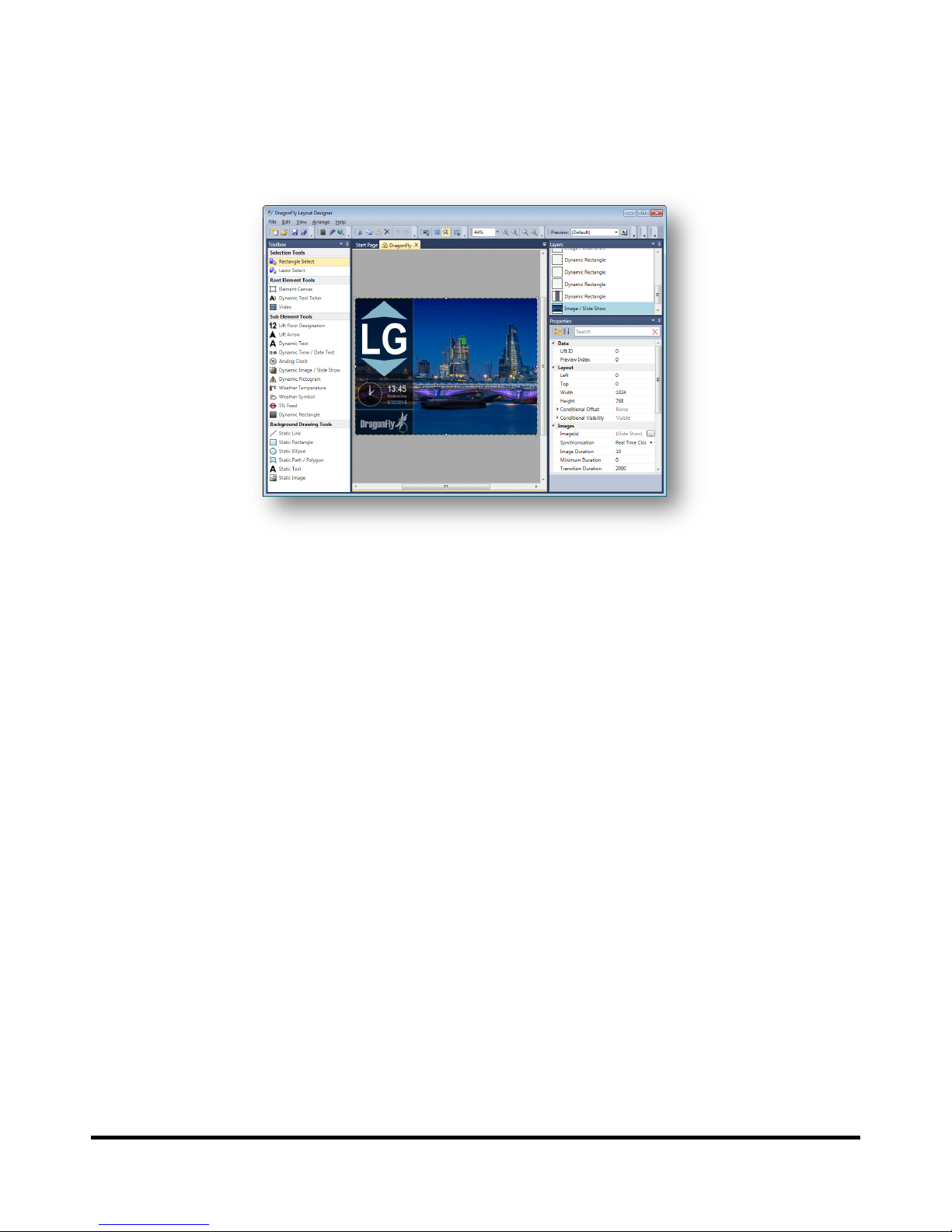
DragonFly Designer Software
The DragonFly Designer software can be used to create and edit screen layouts for any DragonFly display. The
Designer saves and loads *.dfx files directly, and has the ability to create micro SD cards for use with a DragonFly.
The Designer can also create USB update drives for updating an existing DragonFly screen, and can broadcast layouts
over a LAN to multiple screens simultaneously.
The DragonFly Designer is a free utility, and does not require a licence or registration. It requires a PC with Microsoft
Windows XP or later installed (Windows 7 or later is recommended), and the Microsoft .NET Framework 4.0.

Drucegrove DragonFly User Manual 1.4 Page 28
DragonFly Layouts (DFX Files)
A DragonFly screen layout consists of three layers:
1. The background layer, which is a full size static image
2. ‘Root Elements’ on top of the background layer
3. Dynamic ‘Sub Elements’ drawn onto the canvas layers
The ‘Root Elements’ include:
Element Canvas
Dynamic Text Ticker
Video
Dynamic ‘Sub Elements’ include:
Elevator Floor Designation
Elevator Direction Arrow (travelling or intended next direction, up or down)
Dynamic Text (embedded or conditional)
Dynamic Image (slideshow or conditional)
Dynamic Pictogram
Dynamic Time/Date Text
Analogue Clock
Scrolling Ticker Text
Dynamic Rectangle
Weather Temperature (from Ethernet based sensor, or internet based RSS feed)
Weather Symbol (from internet based RSS feed)
Transport for London (TfL) Feed
These elements are all designed into the Designer and DragonFly core software. Additional elements may be added
in future software updates. Please contact Drucegrove to request a new element.
Note: Dynamic elements cannot be drawn directly on to the background; they must be drawn onto a canvas.
Drucegrove DragonFly User Manual 1.4 Page 29
Static Background Image Layer
Every layout has a static background layer that covers the whole area of the layout. If nothing is drawn on to this
layer, the background will be a solid colour. The background is drawn by the DragonFly core software as a static flat
image, so anything drawn on the background is “static” and cannot be dynamically changed, shown, hidden or
moved. Nothing can sit behind the background, and all dynamic elements are drawn on top of the background.
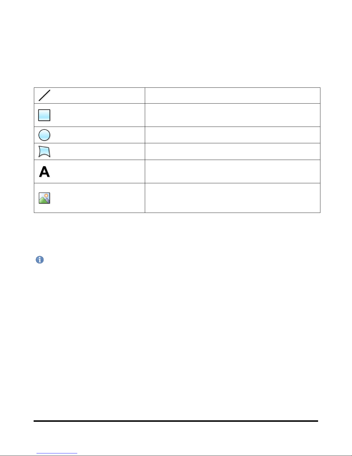
The following static Background Drawing Tools are available:
Static Line
A basic line, with a configurable thickness and colour.
Static Rectangle
A basic rectangle or square, with a configurable fill colour, border colour and
border thickness. The corners of the rectangle can be given a rounded
radius.
Static Ellipse
A basic ellipse or circle, with a configurable fill colour, border colour and
border thickness.
Static Path / Polygon
Any solid shape, with configurable points, fill colour, border colour and
border thickness.
Static Text
Static text, with configurable font, weight, style and fill colour. This text
cannot be changed dynamically by the DragonFly (use the Dynamic Text sub
element for text that needs to change).
Static Image
A static image. This element supports most common formats (BMP, JPEG,
GIF and PNG), and the alpha channel of a 32bit PNG is supported. This image
cannot be changed dynamically by the DragonFly (use the Dynamic Image /
Slide Show sub element for an image that needs to change).
If a full screen background image is required, draw a Static Image over the entire layout. It will be placed on the
background layer automatically behind any dynamic screen elements.
Note: Static background shapes filled with a gradient will be dithered automatically for improved appearance.

Drucegrove DragonFly User Manual 1.4 Page 30
‘Element Canvas’ Root Element Layers
All dynamic ‘Sub Elements’ that are drawn by the DragonFly must be placed in an Element Canvas. When an
individual Sub Element needs to be redrawn, the whole canvas has to be redrawn, so it is advisable to split the layout
into multiple canvases where possible, for best performance on fast updating or animated elements.
Element Canvas backgrounds are “transparent” by default (although they can be given individual solid colour
backgrounds). The transparency only works for the background of a canvas, so if two canvases overlap, sub elements
will only be seen on the canvas that is in front.
Canvases are drawn by the PowerVR graphics hardware in the ARM Cortex processor using OpenGLES. This allows
for animated scrolling, fading and alpha blending effects.
‘Dynamic Ticker Text’ Root Element
The DragonFly can render a smooth horizontally scrolling ‘ticker’ text. The text can either be embedded into the DFX
file, or be configured from a remote source.
Dynamic Ticket Text backgrounds are a solid colour by default, or can be configured to be “transparent”. The
transparency only works for the background of the element, so if two ticker or canvas elements overlap, text or sub
elements will only be seen on the canvas that is in front.
The ticker is drawn by the PowerVR graphics hardware in the ARM Cortex processor using OpenGLES. It is
automatically redrawn asynchronously to all other screen elements. This allows for smooth scrolling, but restricts
the conditional capabilities of the element (ie, it cannot be dynamically moved around the screen based on
conditional events).
‘Video’ Root Element
The DragonFly is capable of supporting a single video element. This is rendered using the hardware DSP in the ARM
Cortex processor. It is automatically rendered asynchronously to all other screen elements. This allows for smooth
playback, but restricts the conditional capabilities of the element (ie, it cannot be dynamically moved around the
screen based on conditional events). Dynamic ‘Sub Elements’ cannot be drawn onto a video element. The video
element should be the same size or larger than the video source. The video element is not recommended for rotated
displays, as performance is poor for rotated H264 playback (rotated MPEG2 performance is not affected). The video
element should not be overlapped by any other root element.
For more information on using the Video element, refer to the Video Element section of this manual (page 35)

Drucegrove DragonFly User Manual 1.4 Page 31
Dynamic Sub Elements
The following Dynamic Sub Elements are available:
Floor Designation
Elevator floor designation characters. The designation will update
automatically from the 2-Wire elevator data input and scroll and/or fade
accordingly.
Arrow
Direction arrow for either the current elevator travelling direction, or the
intended next direction.
The arrow will update automatically from the 2-Wire elevator data input.
The arrow can be configured to show either the up or down direction, or
only up or only down direction.
Dynamic Text
Dynamically drawn text, which can have either a static embedded value
(useful for text appearing over the top of other dynamic sub elements), or
have a remotely configured value, or a conditionally changing value.
Dynamic Image
Dynamically drawn image(s). If more than one image is configured in this
element, they can be displayed as either an automatically advancing timed
slideshow, or as a conditionally selected image. This element supports most
common formats (BMP, JPEG, GIF and PNG), and the alpha channel of a
32bit PNG is supported.
Dynamic Pictogram
Dynamically drawn pictogram(s). The pictograms are selected from a library
of vectorised images that can be resized and recoloured from the Designer
software.
Dynamic Time / Date Text
Digital clock text. The format can be selected, and the text automatically
updates from the on board real time clock on the DragonFly.
Analog Clock
Analog clock. The clock face and hands can be configured, and the clock
automatically updates from the on board real time clock on the DragonFly.
Dynamic Rectangle
Simple solid colour rectangle drawn dynamically by the DragonFly. This can
be used where a rectangle or line needs to be drawn over the top of another
dynamic sub element.
Weather Temperature
Dynamically drawn text based temperature. The temperature can either be
pushed to the feed over a LAN from a server, or pulled directly from a LAN
based temperature sensor or internet based RSS feed. Either a single
temperature or a combination of current, maximum and minimum
temperature can be displayed.
Weather Symbol
Dynamically drawn weather symbol. The library of vectorised symbols exists
in the Designer, and can be resized and recoloured. The symbol index can
either be pushed to the feed over a LAN from a server, or pulled directly
from an internet based RSS feed.
Transport for London (TfL) Feed
Dynamically updated TfL line status. The lines that are displayed can be
selected, and an optional second frame showing status details may be
displayed. The data can either be pushed to the feed over a LAN from a
server, or pulled directly from an internet based RSS feed.
Note: More elements will be made available, and will be fully documented in future versions of this document.

Drucegrove DragonFly User Manual 1.4 Page 32
Element Conditions
All sub elements have the conditional visibility, opacity, left offset and top offset properties. Certain elements can
have conditional values (Dynamic Text and Dynamic Image elements for example). All of these conditions can be
configured using a very similar user interface:
An unlimited number of conditional statements can be built up, with Boolean AND or OR logic between each
statement. The full condition will be read from left to right, line by line by the DragonFly core software for the
element.
Use the button on any line to delete it, or the +And or +Or button to insert a new line.
A conditional statement can look at any of the following:
Current Floor Designation
The current floor designation characters.
Can be an alpha numeric string value, 1 to 4 characters length.
Current Floor Level
The current floor level address, as sent by the IND055.
Can be any integer value between 0 and 127.
Floor Level Position Address
The position address that the DragonFly is set to (using the position dipswitch
or FloorPositionAddress setting)
Floor Level Change Direction
The last direction of change of the floor level address, as sent by the IND055.
Can be one of the following values:
Up
Down
Car Travelling Direction
The current car direction, as sent by the IND055.
Can be one of the following values:
None
Up Only
Up Or Both
Down Only
Down Or Both
Up Or Down
Both
Intended Next Direction
The intended next (lantern) direction, as sent by the IND055.
Can be one of the following values:
None
Up Only
Up Or Both
Down Only
Down Or Both
Up Or Down
Both

Drucegrove DragonFly User Manual 1.4 Page 33
Door Status
The current door status, as sent by the IND055.
Can be one of the following values:
Opening
Open
Closing
Closed
Message Image Number
The current message image code, as sent by the IND055 2-Wire Controller.
Can be any integer value between 0 and 255.
Message Active
Automatically determine the elevator message status based on the current
message image code, as sent by the IND055 2-Wire Controller. The message
response of each image code is determined by the message image library for
the 4.3”, 5.7” and 7.0” screens (ie, image codes 065 to 077 will all translate to
the Out Of Service message)
Can be one of the following values:
Overloaded
Doors Obstructed
On Car Preference
On Priority Service
Under Maintenance
Returning To Ground Floor
On Fire Control
Emergency Fire Service
Emergency Code Blue Mode
Emergency Hospital Service
Emergency Earthquake Mode
Alarm Activated
Alarm Acknowledged
Date
The current date, ignoring time of day.
Time
The current time of day, ignoring date.
Time And Date
The current date and time of day.
Hour of Day
The current hour of the day in 24 hour format.
Can be any integer value between 0 and 23.
Day Of Month
The current day of the month.
Can be any integer value between 1 and 31.
Day Of Week
The current day of the week.
Can be one of the following values:
Sunday
Monday
Tuesday
Wednesday
Thursday
Friday
Saturday
Month Of Year
The current month of the year.
Can be one of the following values:
January
February
March
April
May
June
July
August
September
October
November
December

Drucegrove DragonFly User Manual 1.4 Page 34
Season
The current season.
Can be one of the following values:
Spring
Summer
Autumn
Winter
Year
The current year.
Can be any integer value between 2000 and 2099.
Variable Value
The name of a variable to test needs to be entered between the brackets.
Variable Length
The name of a variable to test needs to be entered between the brackets.
As any of these values are selected, the list available operators will be changed accordingly (ie, greater than and less
than operators will not be available for text based comparisons).

Drucegrove DragonFly User Manual 1.4 Page 35
Video Element
The video element can be added to a layout. Only the size and position of the video element can be defined in the
layout *.dfx file. Elements cannot be drawn onto a video element, and other canvases cannot overlap a video
element. The video element is only supported by the RE2 and RM2 based DragonFly products, and only one video
element is currently supported.
All of the settings for the video element are stored inside the DFX layout file, but these settings may be overridden in
the Settings.xml file. A VideoSettings section needs to exist in the Settings file with a line to set the OverrideSettings
setting to True, as shown below:
<?xml version="1.0" encoding="UTF-8"?>
<!-- Drucegrove TFT2X Indicator Layout File -->
<!-- Copyright (C) 2012 Drucegrove Ltd -->
<Layout>
<About>
<Name>ExampleLayout</Name>
<Creator>RHF</Creator>
<CreationDate>04/01/2012</CreationDate>
</About>
<IndicatorSettings>
...
...
</IndicatorSettings>
<VideoSettings>
<OverrideSettings>True</ OverrideSettings >
<VideoURL>udp://239.0.0.1:5000</VideoURL>
<HideWhenNoVideo>True</HideWhenNoVideo>
<VideoSizeMode>3</VideoSizeMode>
<AudioVolume>5000</AudioVolume>
<VideoThreadPriority>AboveNormal</VideoThreadPriority>
</VideoSettings>
</Layout>

Drucegrove DragonFly User Manual 1.4 Page 36
The following video settings are available:
Setting
Description
Example Value(s)
OverrideSettings
Boolean value, false by default.
If True, the video settings inside the loaded
DFX will be ignored, and the video settings in
the Settings.xml file will be used instead.
True
VideoURL
This is the local file location and name, or the URL
of a live network video stream.
\Storage Card\MyVideo.avi
udp://239.0.0.1:5000
http://www.source.com/stream.asx
VideoSizeMode
This defines how the video is sized in the video
canvas. Valid options are:
0 = Automatic
1 = Fill Window (stretch)
2 = Fill Window (4:3 aspect ratio)
3 = Fill Window (16:9 aspect ratio)
4 = Do Not Resize
0
VideoThreadPriority
This defines the CPU priority of the video thread.
This should not have to be adjusted, but valid
values are:
Highest
AboveNormal
Normal
BelowNormal
Lowest
Normal
HideWhenNoVideo
Can be set to True or False.
If True, the video canvas will be hidden when no
video is present (ie, live network video stream is
disconnected). Alternative screen content can be
positioned behind the video window, to be shown
when the video is not present.
True
Loop
Can be set to True or False.
This is only available for a local video file. If set to
False, the video file will only play once, and then
stop.
True
AudioVolume
Value between 0 and 10000. Zero will mute the
audio, and 10000 is full volume.
10000
AudioBalance
Value between -5000 and 5000 for left/right audio
balance. Negative values are for left balance,
positive values are for right balance.
0

Drucegrove DragonFly User Manual 1.4 Page 37
Supported Video Formats
The DragonFly only supports video playback with the RE2. The ARM Cortex processor on the RE2 has an integrated
Digital Signal Processor (DSP) which is capable of decoding certain video formats without loading the CPU. Other
formats are supported via software decoders which will consume CPU processing time. It is recommended that video
formats supported by the DSP are used, as this will give optimal system performance.
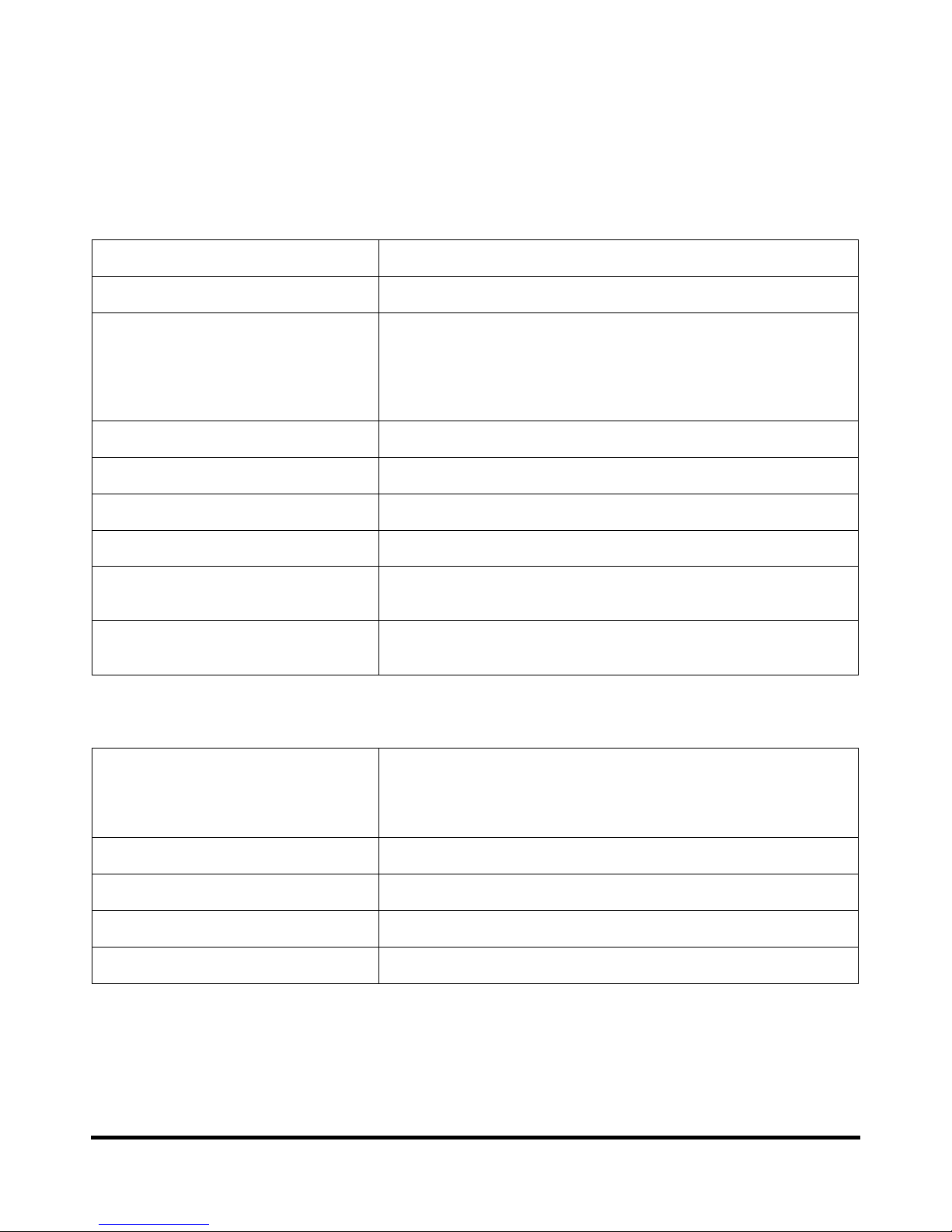
The following table shows current video format support:
Video Format
Software Decoder (CPU)
Hardware Decoder (DSP)
H264, High Profile
H264, Main Profile
H264, Base Profile
MPEG4, Part II
MPEG4, Xvid
MPEG4, DivX
MPEG2, High Profile
MPEG2, Main Profile
MPEG2, Base Profile
MPEG1
WMV
MJPEG
Video performance may be drastically reduced if the Video canvas is smaller than the video resolution.
H264 performance is drastically reduced if the display is rotated. For rotated displays, MPEG2 is recommended.

Drucegrove DragonFly User Manual 1.4 Page 38
Supported Audio Formats for Video
Audio is support is provided by software decoders.
The following table shows current audio format support:
Video Format
Software Decoder (CPU)
MP3
MP2
AAC AC3
Vorbis
PCM Wave
Supported Containers for Video
The video and audio is multiplexed together, and the combination is stored in a file or sent over a network insider a
container. A container is used even if there is only a single stream (ie, video only with no audio will still be inside a
container). The MPEG Transport Stream (MPEG-TS) is most commonly used for live broadcasts, and the DragonFly
only supports this container when used in conjunction with the UDP network protocol.
The following table shows current container support:
Video Format
Software Demux (CPU)
MPEG-TS *
*MPEG-TS support only
available on UDP protocol
AVI
MP4
ASF
MOV
OGG
File or Network Stream
Container
Video
Audio
Container
Video
Audio
Container
Video
Audio

Drucegrove DragonFly User Manual 1.4 Page 39
Supported Network Protocols for Video
Video and/or audio can only be sent over a network as packets inside a container. User Datagram Protocol (UDP) is
often used in live broadcasts because it supports multicasting (see Live Network Video section).
The following table shows current network protocol support:
Video Format
Software Demux (CPU)
UDP *
* UDP protocol only supports
MPEG-TS container
HTTP *
* UDP protocol only supports
MJPEG streams
MMS
RTSP
Live Network Video Overview
For a live network video source, a video streaming device should be present on the Ethernet network. The streaming
device could be anything from an IPTV DVB Gateway coupled with a Transceiver, to an IP Security Camera.
For IPTV, the video should be output as an MPEG Transport Stream via UDP to a Port on an IP Address. The IPTV
streamer can either send the video directly to a single DragonFly via its IP address (unicast), or to a virtual location
on the network where multiple DragonFly units can “tune in” and receive the video simultaneously (multicast).
The Port is a 16 bit value, can be any value between 0 and 65535. Certain ports are reserved under IPv4 (ie, port 80 for
HTTP). Drucegrove generally configure video to be sent to port 5000 by default.
Multicast streaming requires managed switches with IGMP (Internet Group Management Protocol) Querying, which
manages the video stream on the network and directs it to the units on the network that need to receive it. Only one
copy of the video stream exists on the network, regardless of the number of units receiving. This means minimum
bandwidth is required.
Unicast streaming does not require managed network switches (IGMP querying is not required, unlike multicast), but
for each DragonFly unit receiving a copy of the video, the streamer will have to send out a dedicated copy. This
means that for 10 units to receive unicast video, 10 times the network bandwidth is required compared to sending
out a single copy. Video streaming hardware will only be able to support a limited number of unicast streams; in
some cases only a single stream can be output at any one time. Multicast is therefore recommended if more than
one unit on the network is showing video.
IP Addresses are made up of 32 bits. They are typically represented by four byte values (0-255) separated by a
decimal point. If the first four bits (4 most significant bits) of an IP Address are 1110, then this is a multicast IP
Address under the IPv4 standard. This means that multicast streams should be on IP Addresses between the range
224.x.x.x and 239.x.x.x. There does not have to be any hardware on the network configured to the multicast address,
it is just a virtual location, and when the streamer sends data to a valid multicast address the managed switches uses
IGMP Querying to route the video packets to the correct locations. When a DragonFly unit is configured to receive
multicast UDP video, it sends a command to the IGMP Querier, telling it to send it any multicast data destined for
the specified multicast IP Address. Drucegrove generally configure multicast video to be sent to 239.0.0.1 by default.

Drucegrove DragonFly User Manual 1.4 Page 40
Configuring the DragonFly for Live Network Video
The UDP receiver on the DragonFly can be configured to receive unicast or multicast UDP stream using the URL:
udp://239.0.0.1:5000
Additional flags and variables can be added to the end of the URL, by placing a ? after the port, and separating
multiple values with an &, ie:
udp://239.0.0.1:5000?noaudio
udp://239.0.0.1:5000?noaudio&loadtimeout=7000
The following flags are supported:
Flag / Variable
Description
noaudio
Instructs the receiver to ignore audio. If no audio is
present on the stream, this flag must be present or
the receiver will fail to render the stream.
loadtimeout=15000
The number of milliseconds before the receiver will
timout and fail when trying to load a video stream.
The default value is 15000 (15 seconds).
inactivitytimeout=10000
The number of milliseconds before the receiver will
timeout and fail whilst playing a video stream. The
default value is 10000 (10 seconds).
Note: If audio is present but not required to be output, use the noaudio flag for improved video performance.

Drucegrove DragonFly User Manual 1.4 Page 41
DragonFly Variables
The DragonFly software uses variables for dynamic display content. Variables can be referenced in XML files on the
SD card by encapsulating their name with percentage sign characters, ie %VAR1%.
Variable names should always be capitalised.
The following tables list all variables that have been pre-defined, and should be used where necessary over custom
variable names.
The following variable names are used for general and miscellaneous values and states. The ## characters should be
substituted with a numeric value between 01 and 99 (leading zeros are required), and the word “LIFT” can be
replaced by “ELEVATOR”:
Variable
Name
Variable
Description
Data
Type
LOCATION_CITY
The name of the city that the screen is located in
Text
LOCATION_SITE
The name of the site that the screen is located in
Text
LOCATION_BUILDING
The name of the building that the screen is located in
Text
LOCATION_DEPARTMENT
The name of the department that the screen is located in
Text
LOCATION_LIFT_GROUP
The name of the lift group that the screen is located in
Text
LOCATION_LIFT_NAME
The name of the lift that the screen is located in
Text
CURRENT_TEMPERATURE_FULL_VALUE
Current full temperature value from a sensor, including
decimal point and single digit fraction
Text
CURRENT_TEMPERATURE_INT_VALUE
Current temperature value from a sensor, represented as
a rounded down integer
Integer (-99 to 99)
CURRENT_TEMPERATURE_FRACTION_VALUE
Fractional part of the current temperature value from a
sensor, represented as a single digit integer
Integer (0 to 9)
CURRENT_TEMPERATURE_UNIT
Single character (C or F) representing the temperature
unit of measurement from a sensor
Text (1 character)
CURRENT_TEMPERATURE_EXPIRE_TIME
Date and time after which the current temperature from a
sensor is invalid
Date and Time
USER_MESSAGE
General user text (acts as an alias for USER_MESSAGE_00)
Text
USER_MESSAGE_##
General user text (## should be value between 00 and 99)
Text
The following variable names are used for general purpose inputs and outputs. For each variable name listed, the ##
characters should be substituted with a numeric address value between 01 and 63, and the character replaced
with a numeric input value between 01 and 16 (leading zeros are required):
Variable
Name
Variable
Description
Data
Type
GPIO##_
Current state of input/output number at address ##
Boolean
GPIO##_BINARY_VALUE
Integer value representing the binary value of the GPIO
at address ##
Integer
GPIO##_EXPIRE_TIME
Date and time after which the input states from address
## are invalid
Date and Time

Drucegrove DragonFly User Manual 1.4 Page 42
The IND079 uses the following variable names. For each variable name listed, the ## characters should be
substituted with a numeric value between 01 and 63 (leading zeros are required). The word “LIFT” can also be
replaced by “ELEVATOR”.
Variable
Name
Variable
Description
Data
Type
LIFT##_FLOOR_DESIGNATION
Floor designation characters
Text (0 to 4 characters)
LIFT##_FLOOR_LEVEL_ADDR
Floor level address
Integer (0 to 127)
LIFT##_CAR_DIRECTION
Car direction (NONE, UP, DOWN or BOTH)
DirectionState
LIFT##_CAR_DIRECTION_UP
Car up direction
Boolean
LIFT##_CAR_DIRECTION_DOWN
Car down direction
Boolean
LIFT##_NEXT_DIRECTION
Next direction (NONE, UP, DOWN or BOTH)
DirectionState
LIFT##_NEXT_DIRECTION_UP
Next up direction
Boolean
LIFT##_NEXT_DIRECTION_DOWN
Next down direction
Boolean
LIFT##_FRONT_DOORS_STATUS
Front door status (CLOSED, CLOSING, OPEN or OPENING)
DoorState
LIFT##_FRONT_DOORS_OPENING
Front doors opening
Boolean
LIFT##_FRONT_DOORS_CLOSING
Front doors closing
Boolean
LIFT##_REAR_DOORS_STATUS
Rear door status (CLOSED, CLOSING, OPEN or OPENING)
DoorState
LIFT##_REAR_DOORS_OPENING
Rear doors opening
Boolean
LIFT##_REAR_DOORS_CLOSING
Rear doors closing
Boolean
LIFT##_OVERLOADED
‘Overloaded’ message active
Boolean
LIFT##_DOORS_OBSTRUCTED
‘Doors Obstructed’ message active
Boolean
LIFT##_ALARM_ACTIVATED
‘Alarm Activated’ message active
Boolean
LIFT##_ALARM_ACKNOWLEDGED
‘Alarm Acknowledged’ message active
Boolean
LIFT##_EMERGENCY_EARTHQUAKE_MODE
‘Emergency Earthquake Mode’ message active
Boolean
LIFT##_EMERGENCY_CODE_BLUE_MODE
‘Emergency Code Blue Mode’ message active
Boolean
LIFT##_ON_FIRE_CONTROL
‘On Fire Control’ message active
Boolean
LIFT##_EMERGENCY_FIRE_SERVICE
‘Emergency Fire Service’ message active
Boolean
LIFT##_EMERGENCY_HOSPITAL_SERVICE
‘Emergency Hospital Service’ message active
Boolean
LIFT##_RETURNING_TO_GROUND_FLOOR
‘Returning To Ground Floor’ message active
Boolean
LIFT##_OUT_OF_SERVICE
‘Out Of Service’ message active
Boolean
LIFT##_ON_CAR_PREFERENCE
‘On Car Preference’ message active
Boolean
LIFT##_ON_PRIORITY_SERVICE
‘On Priority Service’ message active
Boolean
LIFT##_ON_INSPECTION_SERVICE
‘On Inspection Service’ message active
Boolean
LIFT##_UNDER_MAINTENANCE
‘Under Maintenance’ message active
Boolean
LIFT##_CAR_IMAGE_CODE
Current active car message image code
Integer (0 to 255)
LIFT##_LANDING_IMAGE_CODE
Current active landing message image code
Integer (0 to 255)
LIFT##_EXPIRE_TIME
Date and time after which the lift information is invalid
Date and Time

Drucegrove DragonFly User Manual 1.4 Page 43
The following variable names are used for weather feeds. The ## characters should be substituted with a numeric
value between 01 and 07 (leading zeros are required). The CURRENT temperature variables are aliases for DAY00
variables:
Variable
Name
Variable
Description
Data
Type
WEATHER_LOCATION
Location (city) for the weather
Text
WEATHER_CURRENT_FULL_DAY
Day of the week for the current weather
Text
WEATHER_CURRENT_SHORT_DAY
Three character representing the day of the week for the
current weather
Text (3 characters)
WEATHER_CURRENT_DESCRIPTION
Current weather description (ie, “Partly Cloudy”)
Text
WEATHER_CURRENT_TEMP_C
Current Temperature in degrees Celsius (may have a
decimal point and fractional part)
Text
WEATHER_CURRENT_TEMP_F
Current Temperature in degrees Fahrenheit (may have a
decimal point and fractional part)
WEATHER_CURRENT_TEMP_MAX_C
Current Maximum Temperature in degrees Celsius (may
have a decimal point and fractional part)
Text
WEATHER_CURRENT_TEMP_MAX_F
Current Maximum Temperature in degrees Fahrenheit
(may have a decimal point and fractional part)
WEATHER_CURRENT_TEMP_MIN_C
Current Minimum Temperature in degrees Celsius (may
have a decimal point and fractional part)
Text
WEATHER_CURRENT_TEMP_MIN_F
Current Minimum Temperature in degrees Fahrenheit
(may have a decimal point and fractional part)
WEATHER_CURRENT_ICON_INDEX
Icon index (between 0 and 32), defined as follows:
0 = Clear Night
1 = Clear Day
2 = Partly Cloudy Night
3 = Partly Cloudy Day
4 = Sand Storm
5 = Mist
6 = Fog
7 = Grey Cloud
8 = Black Cloud
9 = Light Rain Night
10 = Light Rain Day
11 = Fine Rain
12 = Light Rain
13 = Heavy Rain Night
14 = Heavy Rain Day
15 = Heavy Rain
16 = Sleet Night
17 = Sleet Day
18 = Sleet
19 = Hail Night
20 = Hail Day
21 = Hail
22 = Light Snow Night
23 = Light Snow Day
24 = Light Snow
25 = Heavy Snow Night
26 = Heavy Snow Day
27 = Heavy Snow
28 = Storm Night
29 = Storm Day
30 = Storm
31 = Hurricane / Tornado
32 = Hazy
Integer
WEATHER_DAY##_FULL_DAY
Day of the week for the weather on day ##
Text
WEATHER_DAY##_SHORT_DAY
Three character representing the day of the week for the
weather on day ##
Text (3 characters)
WEATHER_DAY##_DESCRIPTION
Weather description (ie, “Partly Cloudy”) on day ##
Text
WEATHER_DAY##_TEMP_C
Temperature in degrees Celsius (may have a decimal
point and fractional part) on day ##
Text
WEATHER_DAY##_TEMP_F
Maximum Temperature in degrees Fahrenheit (may have
a decimal point and fractional part) on day ##
WEATHER_DAY##_TEMP_MAX_C
Maximum Temperature in degrees Celsius (may have a
decimal point and fractional part) on day ##
Text
WEATHER_DAY##_TEMP_MAX_F
Maximum Temperature in degrees Fahrenheit (may have
a decimal point and fractional part) on day ##
WEATHER_DAY##_TEMP_MIN_C
Minimum Temperature in degrees Celsius (may have a
decimal point and fractional part) on day ##
Text
WEATHER_DAY##_TEMP_MIN_F
Minimum Temperature in degrees Fahrenheit (may have
a decimal point and fractional part) on day ##
WEATHER_DAY##_ICON_INDEX
Icon index (between 0 and 32) on day ##
Integer
WEATHER_EXPIRE_TIME
Date and time after which the weather feed is invalid
Date and Time

Drucegrove DragonFly User Manual 1.4 Page 44
The following variable names are used for TfL feeds:
Variable
Name
Variable
Description
Data
Type
TFL_BAKERLOO_STATUS
Short status for the Bakerloo line
Text
TFL_BAKERLOO_STATUS_DETAILS
Full status details for the Bakerloo line when it is disrupted
Text
TFL_BAKERLOO_DISRUPTED
Boolean value for the disrupted status of the Bakerloo line
Boolean
TFL_CENTRAL_STATUS
Short status for the Central line
Text
TFL_CENTRAL_STATUS_DETAILS
Full status details for the Central line when it is disrupted
Text
TFL_CENTRAL_DISRUPTED
Boolean value for the disrupted status of the Central line
Boolean
TFL_CIRCLE_STATUS
Short status for the Circle line
Text
TFL_CIRCLE_STATUS_DETAILS
Full status details for the Circle line when it is disrupted
Text
TFL_CIRCLE_DISRUPTED
Boolean value for the disrupted status of the Circle line
Boolean
TFL_DISTRICT_STATUS
Short status for the District line
Text
TFL_DISTRICT_STATUS_DETAILS
Full status details for the District line when it is disrupted
Text
TFL_DISTRICT_DISRUPTED
Boolean value for the disrupted status of the District line
Boolean
TFL_HAMMERSMITHANDCITY_STATUS
Short status for the Hammersmith And City line
Text
TFL_HAMMERSMITHANDCITY_STATUS_DETAILS
Full status details for the H’smith & City line when it is disrupted
Text
TFL_HAMMERSMITHANDCITY_DISRUPTED
Boolean value for the disrupted status of the H’smith & City line
Boolean
TFL_JUBILEE_STATUS
Short status for the Jubilee line
Text
TFL_JUBILEE_STATUS_DETAILS
Full status details for the Jubilee line when it is disrupted
Text
TFL_JUBILEE_DISRUPTED
Boolean value for the disrupted status of the Jubilee line
Boolean
TFL_METROPOLITAN_STATUS
Short status for the Metropolitan line
Text
TFL_METROPOLITAN_STATUS_DETAILS
Full status details for the Metropolitan line when it is disrupted
Text
TFL_METROPOLITAN_DISRUPTED
Boolean value for the disrupted status of the Metropolitan line
Boolean
TFL_NORTHERN_STATUS
Short status for the Northern line
Text
TFL_NORTHERN_STATUS_DETAILS
Full status details for the Northern line when it is disrupted
Text
TFL_NORTHERN_DISRUPTED
Boolean value for the disrupted status of the Northern line
Boolean
TFL_PICCADILLY_STATUS
Short status for the Piccadilly line
Text
TFL_PICCADILLY_STATUS_DETAILS
Full status details for the Piccadilly line when it is disrupted
Text
TFL_PICCADILLY_DISRUPTED
Boolean value for the disrupted status of the Piccadilly line
Boolean
TFL_VICTORIA_STATUS
Short status for the Victoria line
Text
TFL_VICTORIA_STATUS_DETAILS
Full status details for the Victoria line when it is disrupted
Text
TFL_VICTORIA_DISRUPTED
Boolean value for the disrupted status of the Victoria line
Boolean
TFL_WATERLOOANDCITY_STATUS
Short status for the Waterloo And City line
Text
TFL_WATERLOOANDCITY_STATUS_DETAILS
Full status details for the W’loo & City line when it is disrupted
Text
TFL_WATERLOOANDCITY_DISRUPTED
Boolean value for the disrupted status of the W’loo & City line
Boolean
TFL_OVERGROUND_STATUS
Short status for the Overground
Text
TFL_OVERGROUND_STATUS_DETAILS
Full status details for the Overground when it is disrupted
Text
TFL_OVERGROUND_DISRUPTED
Boolean value for the disrupted status of the Overground
Boolean
TFL_DLR_STATUS
Short status for the DLR
Text
TFL_DLR_STATUS_DETAILS
Full status details for the DLR when it is disrupted
Text
TFL_DLR_DISRUPTED
Boolean value for the disrupted status of the DLR
Boolean
TFL_EXPIRE_TIME
Date and time after which the TfL feed is invalid
Date and Time

Drucegrove DragonFly User Manual 1.4 Page 45
Live Data Feeds
Information from live data feeds can be downloaded, parsed and displayed on a DragonFly display. An internet
connection is generally required for this feature, although certain local Ethernet based sensors can be used (ie, an
Ethernet temperature sensor).
RSS (XML) Feeds
Most information feeds are provided in Really Simple Syndication (RSS) format. The data is stored in XML elements
which can be easily parsed. Websites that provide an RSS feed often link to the feed via a small orange button ( ).
The following is an example of an RSS XML feed:
<?xml version="1.0" encoding="UTF-8"?>
<rss xmlns:atom="http://www.w3.org/2005/Atom" xmlns:georss="http://www.georss.org/georss"
version="2.0">
<channel>
<atom:link
href="http://open.live.bbc.co.uk/weather/feeds/en/2643743/observations.rss" rel="self"
type="application/rss+xml" />
<title>BBC Weather - Observations for London, United Kingdom</title>
<link>http://www.bbc.co.uk/weather/2643743</link>
<description>Latest observations for London from BBC Weather, including weather,
temperature and wind information</description>
<language>en</language>
<copyright>Copyright: (C) British Broadcasting Corporation, see
http://www.bbc.co.uk/terms/additional_rss.shtml for more details</copyright>
<pubDate>Fri, 13 Nov 2015 08:35:11 +0000</pubDate>
<item>
<title>Friday - 08:00 GMT: Sunny, 9°C (48°F)</title>
<link>http://www.bbc.co.uk/weather/2643743</link>
<description>Temperature: 9°C (48°F), Wind Direction: South South Westerly, Wind
Speed: 10mph, Humidity: 72%, Pressure: 1020mb, Rising, Visibility: Good</description>
<pubDate>Fri, 13 Nov 2015 08:35:11 +0000</pubDate>
<guid isPermaLink="false">http://www.bbc.co.uk/weather/2643743-2015-1113T08:35:11.000Z</guid>
<georss:point>51.50853 -0.12574</georss:point>
</item>
</channel>
</rss>
Text Feeds
Feeds may be provided in a non-XML based format. In this case the feeds will have to be parsed as text files.
The following is an example of a text feed:
[{"ADHERENCE":"2","BLOCKID":"23","BLOCK_ABBR":"1101","DIRECTION":"Southbound","LATITUDE":"33.7964731","LONGITUDE":"-
84.3880132","MSGTIME":"11\/13\/2015 5:02:27
AM","ROUTE":"110","STOPID":"900644","TIMEPOINT":"Peachtree Hills &
Peachtree","TRIPID":"4853908","VEHICLE":"1442"}]
Note: It is possible to parse a web page’s HTML source as a text file, but be aware that the HTML structure of a
web page is likely to change without warning.

Drucegrove DragonFly User Manual 1.4 Page 46
The following is an example of a Parser XML file:
<?xml version="1.0" encoding="UTF-8"?>
<Parser>
<Settings>
<Arg ID="id"
Name="Location ID"
Description="The BBC Weather location ID" />
</Settings>
<Variables>
<Variable Name="WEATHER_SOURCE" Value="BBC Weather" />
<DateTime Name="WEATHER_UPDATED" />
</Variables>
<Source URL="http://open.live.bbc.co.uk/weather/feeds/en/{id}/observations.rss">
<Read Mode="xml"
Path="/rss/channel/item/title"
Instance="1"
Variable="WEATHER_TITLE" />
</Source>
</Parser>
The parser has a single Argument (shown in red). Arguments are optional, and are usually used in the source URL for
the feed. If the feed only has a single source URL with no variables then the arguments do not need to be included.
In this example, the BBC feed URL has an ID number for the location which has been defined here as an argument
called “id”. When this parser is selected in the DragonFly Designer or Remote Configuration software then the user
will be required to enter the “Location ID” for the feed.
The parser can be configured to output variables that do not relate to a downloaded feed, such as static text or the
current date and time. This parser will output a single static Variable (shown in purple) called “WEATHER_SOURCE”
which will always be given the value “BBC Weather”. This parser will also output a DateTime variable called
“WEATHER_UPDATED” (shown in orange. The value of this DateTime variable will be set to the current date and
time.
The parser has a single Source URL (shown in green). The URL includes the “id” attribute encapsulated in braces
(highlighted in yellow). When the URL is downloaded, {id} will be replaced by the valued of the “id” argument.
Once the data is downloaded from the URL, Read Actions are performed. There is one read action in this example
(shown in blue). The read mode of this action is “xml”, which means the data will be parsed as XML from the path
specified by the “Path” attribute.
There is only a single instance of the <title> element, so the “Instance” attribute is set to “1”. Had there have been
multiple <title> elements then the instance attribute would instruct the parser on which element to select.
Finally, the Variable specified in this read action instructs the parser to place the value of the read into a variable
called “WEATHER_TITLE”. This would then mean that DragonFly layout elements can use or display the value of the
weather title by referencing the “WEATHER_TITLE” variable.
Note: It is possible to nest read actions. A read action will be performed on its parent’s resultant data.

Drucegrove DragonFly User Manual 1.4 Page 47
Parser Arguments
The following attributes need to be defined per parser Argument:
ID
The text string that will be defined in the source URL within braces.
Note: Do not include the braces in this definition.
Name
The friendly display name of this argument when it is asked for by the
DragonFly Designer or Remote Configuration software.
Description
Optional friendly description of this argument when it is asked for by the
DragonFly Designer or Remote Configuration software.
Variables
The following attributes may be defined per static Variable:
Name
The name of the data variable to store the value in.
Value
The text to be placed in the variable value.
This may contain arguments by including argument IDs within braces.
ValueIf
Optional list of semi colon separated variable values.
The test and result value should be separated by a colon character.
The test is not case sensitive.
If colons or semi colons need to be used as part of the string, they should be
escaped by a back slash character (eg “\:”).
If back slashes need to be used as part of the string, they should be escaped
by another back slash character (eg “\\”).
Trim
Optional boolean value, false by default.
If True, white spaces (space, tab and carriage return characters) will be
trimmed from the start and end of the resultant text value.
Format
Optional formatting of the resultant value.
Can be one of the following values:
None
LowerCase
UpperCase
TitleCase
SentenceCase
Replace
Optional list of semi colon separated search and replace text values.
Each search and replace value should separated by a colon character.
The search is not case sensitive.
If colons or semi colons need to be used as part of the string, they should be
escaped by a back slash character (eg “\:”).
If back slashes need to be used as part of the string, they should be escaped
by another back slash character (eg “\\”).

Drucegrove DragonFly User Manual 1.4 Page 48
The following attributes may be defined per DateTime variable:
Name
The name of the data variable to store the value in.
Format
The format of the date and/or time to store in the variable value in.
AddMilliseconds
Optional offset value for the millisecond part of the time.
Note: This may be positive or negative.
AddSeconds
Optional offset value for the second part of the time.
Note: This may be positive or negative.
AddMinutes
Optional offset value for the minute part of the time.
Note: This may be positive or negative.
AddHours
Optional offset value for the hour part of the time.
Note: This may be positive or negative.
AddDays
Optional offset value for the day part of the time.
Note: This may be positive or negative.
AddMonths
Optional offset value for the month part of the time.
Note: This may be positive or negative.
AddYears
Optional offset value for the year part of the time.
Note: This may be positive or negative.

Drucegrove DragonFly User Manual 1.4 Page 49
Source URL
The following attributes may be defined per Source:
URL
The URL to download the raw feed data from.
This may contain arguments by including argument IDs within braces.
Read Actions
The following attributes may be defined per Read action:
Mode
The mode of the read action.
Can be one of the following values:
XML
Text
Variable
Optional name of the data variable to store the resultant data in.
Note: The variable may not be defined here if further Read actions are to be
performed on the resultant data.
VariableIf
Optional list of semi colon separated variable result values.
The test and result value should be separated by a colon character.
The test is not case sensitive.
If colons or semi colons need to be used as part of the string, they should be
escaped by a back slash character (eg “\:”).
If back slashes need to be used as part of the string, they should be escaped
by another back slash character (eg “\\”).
Default
Optional default result value if the read action is not successful.
Trim
Optional boolean value, true by default.
If True, white spaces (space, tab and carriage return characters) will be
trimmed from the start and end of the resultant text value.
DataType
Optional data type of the resultant value.
Can be one of the following values:
Text
Boolean
Integer
Float
DateTime
The value will be read as text, converted into the data type, and then the
result will be converted back to text.
Round
Optional boolean value, false by default.
If True and the data type is either Integer or Float, the value will be rounded in
the conversion (the decimal part of the number will subsequently be lost if the
data type is Integer).
RoundDecimalPlaces
Optional number of decimal places to round to, zero by default.
ParseDateTimeFormat
Optional format of the date and time to parse the data as. If the source data is
not in this format, conversion to the DateTime data type will fail and the
variable value will fall back to its default value.
ResultDateTimeFormat
Optional format of the date and time to convert the parsed DateTime value to
when it is subsequently stored as a text value.
Format
Optional formatting of the resultant value.
Can be one of the following values:
None
LowerCase
UpperCase
TitleCase
SentenceCase

Drucegrove DragonFly User Manual 1.4 Page 50
Replace
Optional list of semi colon separated search and replace text values.
Each search and replace value should separated by a colon character.
The search is not case sensitive.
If colons or semi colons need to be used as part of the string, they should be
escaped by a back slash character (eg “\:”).
If back slashes need to be used as part of the string, they should be escaped
by another back slash character (eg “\\”).
Converter
Optional converter to run on the value, None by default.
Can be one of the following values:
None
Contains:{value}
ContainsCaseSensitive:{value}
TemperatureCtoF
TemperatureFtoC
Prefix
Optional text value to prefix to the start of the result value after all other
formatting and conversions.
Suffix
Optional text value to append to the end of the result value after all other
formatting and conversions.
XML Read Actions
The following attributes may be defined per read action if the Mode is set to “XML”:
Path
Optional XML path of the element.
If the path is excluded, then the Attribute should be defined instead.
Note: The path should start with and be separated by forward slash
characters (/), and should includes the top level “root” node, ie:
“/rss/channel/item/title”
Attribute
Optional XML attribute name of the element.
If this value contains an equals character (=), then the value of the attribute
will also be tested.
When used in conjunction with a Path definition, this instructs the read action
to find the first element with the path specified by Path that contains an
attribute with the name (and value if the equals character is included)
specified by Attribute.
Instance
Optional instance of the element node defined by the Path.
NameSpacePrefix
Optional name of the namespace to use for the XML path.
NameSpaceURL
Optional URL of the namespace to use for the XML path.

Drucegrove DragonFly User Manual 1.4 Page 51
Text Read Actions
The following attributes may be defined per read action if the Mode is set to “Text”:
StartText
Optional start text to look for.
Note: The data will be read from the first character after the start text.
StartInstance
Optional instance of the start text to look for.
StartOffset
Optional offset of the start position for the read.
EndText
Optional end text to look for.
Note: The data will be read up the character before the end text.
EndInstance
Optional instance of the end text to look for.
Note: The end text is only searched for after the position of the start text.
EndOffset
Optional offset of the end position for the read.
Note:If no EndText is specified and EndOffset positive, the end position is taken
as the start position offset by EndOffset. If no EndText is specified and
EndOffset negative, the end position is taken as the end of the data offset by
EndOffset.
Instance
Optional instance of the text found between StartText and EndText.
Contains
Optional text value that the text found between StartText and EndText must
contain.
ContainsCaseSensitive
Optional boolean value, false by default.
Determines if the Contains test is case sensitive.

Drucegrove DragonFly User Manual 1.4 Page 52
Using the DragonFly Designer
Tutorial 1: Opening and Editing a Template Layout
When the DragonFly Designer is started, the following screen will be shown:
The Start Page lists shortcuts to template and recently saved layouts. Template layouts are indicated by a small lock
icon, and are read-only – they can only be saved as new *.dfx files.
Open the David Jones layout:
The layout is shown in the centre of the window. The layout view can be panned and zoomed using the mouse.
Scrolling the mouse wheel zooms in and out on the mouse cursor, and clicking the middle mouse button resets the
zoom level and view to bring the whole layout into view.

Drucegrove DragonFly User Manual 1.4 Page 53
The panels docked to the left and right can be resized and minimised. Minimising the Properties panel expands the
Layers panel, which lists all root level elements with their associated sub elements.
The order of the elements in the Layers panel is the z-order on the layout itself, so if an element is at the top of the
list then it will be the front-most element on the layout.
Elements can be selected by either clicking on them in the layout view or selecting them in the Layer panel.
If we select all of the root elements inside the root Element Canvas elements and delete them, we can see the root
level elements and the background layer.

Drucegrove DragonFly User Manual 1.4 Page 54
An Element Canvas can only be selected and moved or resized in the layout view if it is empty. Once it contains sub
elements, it can only be selected by clicking on it in the Layer panel, and can only be modified using the Properties
panel.
If we delete all of the root elements, we’re just left with the Background layer.
The Background layer is rendered by the DragonFly as one full size bitmap image. It is therefore static, and so
anything drawn on this layer cannot be dynamically changed by the DragonFly.
Close the template layout (without saving), and re-open it to recover all of the deleted elements.
Restore the Properties panel, and zoom in on the Element Canvas that contains the arrow and floor designation:

Drucegrove DragonFly User Manual 1.4 Page 55
The Properties panel lists all of the associated properties of the selected element. These range from the basic size
and position of the element, to colours, fonts and transition effects. Dynamic visibility, opacity and position
conditions can also be configured for all sub elements.
Properties can only be configured when a single element is selected. When a group of elements are selected, only
the size and position of the group can be configured.

Drucegrove DragonFly User Manual 1.4 Page 56
Tutorial 2: Previewing the Layout
The layout view shows a live representation of the current layout based on a number of variables. Preview
configurations can be created and quickly switched between using the Preview toolbar at the top of the window.
Clicking on the configure button next to the preview drop down menu opens the following dialog:
Only the floor designation on the default configuration can be changed. It is recommended that the widest floor
designation that is likely to be encountered be left as the default, as this can then be used to ensure that enough
space is given to any floor designation elements drawn on the layout.

Drucegrove DragonFly User Manual 1.4 Page 57
Click the Add Preview button to add a new preview. Give it the name Floor 1:
A wide range of variables can be configured for a custom preview. If any variables are not overridden in a custom
preview, then the default values will be adopted by these variables.
Override the floor position and direction variables, and set the floor designation to 1 and the car direction to Down:

Drucegrove DragonFly User Manual 1.4 Page 58
Clicking OK will return to the layout view and select the Floor 1 preview:
Note that the car direction arrow now points down, and the floor designation element shows 1 rather than LG.
Use the preview drop down menu in the Preview toolbar to switch between previews.

Drucegrove DragonFly User Manual 1.4 Page 59
Tutorial 3: Creating an SD Card
All DragonFly devices have a micro SD card, which contains the DragonFly core software, configuration files and the
layout *.dfx file. This SD card can be created by the Designer software.
A micro SD card slot must be present on the PC. Find the drive letter of this slot, and then in the Designer software
click on Create SD Card... under the File menu:
The following dialog will be shown:
Note that the More DragonFly Settings... link may be unavailable on this dialog. This will occur if the layout is an
unsaved template. To make this link available, cancel the dialog and save the layout to a *.dfx file.

Drucegrove DragonFly User Manual 1.4 Page 60
Ensure that the microSD Card Drive is set to the correct drive letter, and click on the More DragonFly Settings... link:
The settings shown on this dialog will be saved to the Settings.xml and Identity.xml files on the SD card. These
settings can all be left with their default values. Click OK to return to the Create DragonFly SD Card dialog.
Ensure a micro SD card is inserted into the drive slot, and then click the Create button. The micro SD card will be
formatted and all software and files copied to it automatically. Once it has been created, simply insert it into a
DragonFly unit and reboot it.

Drucegrove DragonFly User Manual 1.4 Page 61
Tutorial 4: Creating an Automatic Update USB Drive
If a DragonFly unit already has a micro SD card and it is running, the layout can be updated or changed using a USB
drive.
Insert a USB drive into a USB port on the PC. Find the drive letter of this USB drive, and then in the Designer software
click on Create Automatic Update USB Drive... under the File menu:
The following dialog will be shown:
Click the Create button. The micro SD card will be formatted and all software and files copied to it automatically.
Once it has been created, simply insert it into a DragonFly unit and reboot it.
Note: Only units that have the correct screen resolution for the current layout will be updated.

Drucegrove DragonFly User Manual 1.4 Page 62
Tutorial 5: Broadcasting a Layout over a LAN
If there are DragonFly screens on the same Local Area Network as the PC running the Designer software, then the
layout can be broadcast over the network to these screens.
Ensure the DragonFly units on the network are on the same subnet as the PC, and then in the Designer software click
on Broadcast Layout Over Network... under the File menu.
The following dialog will be shown:
Click the Broadcast button to send the layout to all DragonFly units on the network.
Note: Only units that have the correct screen resolution for the current layout will be updated.

Drucegrove DragonFly User Manual 1.4 Page 63
Tutorial 6: Creating a New Layout
To create a new layout from scratch, click on New under the File menu:
The following dialog will be shown:
Enter DemoLayout as the layout name, and ensure the layout size is 1024×768. Click on OK to create the layout.

Drucegrove DragonFly User Manual 1.4 Page 64
It is recommended to save the layout regularly. Click on Save under the File menu, and create a DemoLayout.dfx file
to save the layout as:
The first element that we want to add to this layout is a floor designation, to make this screen act as an elevator
position indicator. Click on the Elevator Floor Designation in the left hand Toolbox panel. The following message will
be displayed:
Sub elements can only be drawn inside a root Element Canvas, so we need to add one of these before we can add
the floor designation element.

Drucegrove DragonFly User Manual 1.4 Page 65
The element canvas has been highlighted in the toolbox, so click on it to add it:
Draw the element canvas in a position as shown below:

Drucegrove DragonFly User Manual 1.4 Page 66
We can now click on the Elevator Floor Designation sub element in the toolbox:
Draw the floor designation in a position as shown below:

Drucegrove DragonFly User Manual 1.4 Page 67
Next click on the Elevator Arrow sub element in the toolbox:
Draw the arrow in a position as shown below:

Drucegrove DragonFly User Manual 1.4 Page 68
Tutorial 7: Setting a Background Image
The Background layer is a solid colour by default. It can be drawn on to using the Background Drawing Tools in the
toolbox.
To set the entire background to one large image, click on Static Image under the Background Drawing Tools:
Select an image file to use as the background. For this tutorial we’ll use the Desert.jpg image which can be found
under the Sample Pictures folder in the Pictures directory on most Windows based PCs:

Drucegrove DragonFly User Manual 1.4 Page 69
Draw the image over the whole layout. It can be repositioned once drawn if it is not initially in the correct place. The
Properties panel on the right hand side can also be used to position the image. Ensure the Left and Top properties
are both 0, the Width property is 1024 and the Height property is 768:
Once drawn, the image can be changed by clicking on the “...” button on the Image property, or by double clicking
on the image in the layout view.

Drucegrove DragonFly User Manual 1.4 Page 70
Tutorial 8: Drawing on the Background Layer
On the DemoLayout, the floor designation and arrow are currently white on a pale blue sky background. We should
improve the contrast of these elements so that they are easier to read.
We could change the colour of the elements, or we could add a background. The easiest way to add a background
would be to click on the element canvas (it can only be clicked on in the Layers panel since it has child elements),
and then change its Background Colour to something non-transparent:
Alternatively we could draw our own background behind the element canvas. This is a slightly more flexible method,
and allows the background to be made semi-transparent.

Drucegrove DragonFly User Manual 1.4 Page 71
Set the element canvas’s Background Colour back to transparent, and then click on Static Rectangle under the
Background Drawing Tools in the toolbox:
Draw the rectangle in a position as shown below:

Drucegrove DragonFly User Manual 1.4 Page 72
The rectangle will take on the default foreground colour by default, so we need to change the Fill Colour property.
With the rectangle still selected, click on the drop down next to the Fill Colour property in the Properties panel, and
change the colour to black:
Note that the rectangle has automatically been placed behind the arrow floor designation, even though we drew it
after placing those elements. This has occurred because the Static Rectangle is drawn onto the Background layer
which always sits at the bottom of the z-order (so is always rear-most). The static background drawing tools can only
be drawn to this Background layer, and the Background layer cannot be moved.
Change the Opacity property to 60 to make the rectangle 60% translucent:

Drucegrove DragonFly User Manual 1.4 Page 73
Finally, change the Corner Radius property to 20 to give the rectangle rounded corners:

Drucegrove DragonFly User Manual 1.4 Page 74
Tutorial 9: Adding and Configuring Screen Elements
We can add as many screen elements as we like to the layout. All dynamic Sub Elements must be drawn inside a root
Element Canvas. If we attempt to add an element now, we will only be able to place it in the element canvas that
contains the arrow and floor designation.
Add another Element Canvas to the layout. Draw it in the position shown below:
Click on the Analog Clock element in the toolbox. The element canvases will be highlighted to show where the clock
can be drawn:

Drucegrove DragonFly User Manual 1.4 Page 75
Draw the analog clock into the element canvas that we’ve just created, in the position shown below:
Next, click on the Dynamic Text Ticker root element:

Drucegrove DragonFly User Manual 1.4 Page 76
The following dialog will be shown. Enter “Welcome to our building...” as the embedded text, and click on OK:
Note that the dynamic ticker text is a root level element, so it does not need to be positioned inside an element
canvas. We can therefore draw it in the position shown below:

Drucegrove DragonFly User Manual 1.4 Page 77
Tutorial 10: Adding a Dynamic Text Element
The Dynamic Text element is incredibly flexible. Text can be shown as a timed slideshow, or based on dynamically
changing conditions, or a combination of both. The dynamic text element is drawn in real-time by the DragonFly and
can just be used to draw simple non-changing “static” text over the top of dynamically changing elements if desired.
First, add an Element Canvas in the position shown below:
Then click on the Dynamic Text element in the toolbox. The following dialog will be shown:

Drucegrove DragonFly User Manual 1.4 Page 78
Enter the text “Hello World” under the Embedded text section, and click OK:
The “Hello World” text will be drawn on the layout as shown below:
This text will not change, but it can be positioned on top of dynamically changing elements (unlike the Static Text
element which is placed on the background layer).

Drucegrove DragonFly User Manual 1.4 Page 79
The Dynamic Text element has several properties which are listed on the Properties panel. Change the Font Size
property to a value of 64 to increase the size of the text:
The font family and style can also be configured here, as well as the text’s fill colour and opacity. The text can also be
programmed to show or hide itself based on conditions (Conditional Visibility), or move around its element canvas
based on conditions (Conditional Offset).

Drucegrove DragonFly User Manual 1.4 Page 80
Tutorial 11: Configuring a Dynamic Text Element to update based on Conditions
By default the Dynamic Text element is configured to show Dynamic Text, which is either fixed embedded text or a
remotely updatable data field or variable. The element can be configured to change its text value based on
Conditions. These conditions could be related to the position, direction or status of the elevator car, or the time of
day, the date or the season. Conditions can be combined with Boolean logic, and any conditional statement can be
made up of an unlimited number of statements that can be combined with AND, OR, NAND or NOR logic.
Click on the “...” button on the Dynamic Text element’s Text property, or double click on the Dynamic Text element
in the layout view to display the following dialog:
Change the category in the drop down box at the top of the dialog from Dynamic Text to Conditional Text:

Drucegrove DragonFly User Manual 1.4 Page 81
The dialog will change, as shown below. There are currently no conditions set up, so the text element will fall back to
its Default Text value which is configurable at the bottom of the dialog, and in this example is “Hello World”.
Click on the + If button to add a new condition:
Set the first condition to “If Current Floor Designation = G” and then click on final drop down box to enter a text
value “Ground Floor”. Text can be split into multiple lines if desired (and the line spacing is configurable in the
Dynamic Text element’s properties), so insert a carriage return between “Ground” and “Floor” to split it over two
lines as follows:

Drucegrove DragonFly User Manual 1.4 Page 82
Click on the + Or button to add a second condition:
Set the second condition to “If Current Floor Designation = 1” and then click on final drop down box to enter a text
value “First Floor”, again split over two lines:

Drucegrove DragonFly User Manual 1.4 Page 83
Conditions are evaluated by the DragonFly from top to bottom, and will fall to the Default Text value at the bottom
of the dialog if no condition is met. Conditions can be added with And and Or based Boolean logic as necessary. The
operator for each condition can be configured accordingly based on the type of condition. All conditions have the
Equal To and Not Equal To operators available (allowing for AND, OR, NAND and NOR Boolean logic), and conditions
where a numerical or date/time based value is tested have additional Greater Than, Greater Than Or Equal To, Less
Than and Less Than Or Equal To operators available.
Click OK to close the dialog, and the Dynamic Text element will show its default value “Hello World”:
If we now create a micro SD card (File → Create SD Card...), and insert the SD card into a DragonFly TFT500 with an
appropriate TFT screen (10.4” 4:3 or 15” 4:3), then the following will be displayed on the screen:

Drucegrove DragonFly User Manual 1.4 Page 84
Tutorial 12: Configuring a Dynamic Text Element to act as a timed Text Slideshow
The Dynamic Text element can be configured to show multiple text values one after another as a timed text
“slideshow”. Individual text slides can be configured with display times and conditions.
Click on the “...” button on the Dynamic Text element’s Text property, or double click on the Dynamic Text element
in the layout view to display the following dialog. Change the category in the drop down box at the top of the dialog
to Text Slide Show:
Click on the + Add button to add a new slide:

Drucegrove DragonFly User Manual 1.4 Page 85
Click on the large drop down box to enter the text for this first slide. The text can be split over multiple lines if
desired. Enter the text “My Message 1” as shown below:
Click off the text box to collapse it, and then click on the + Add button to add a second slide:
Set the text of this second slide to “My Message 2” as shown below:

Drucegrove DragonFly User Manual 1.4 Page 86
Add three more slides as shown below:
If we were to click OK at this point, and load this layout on to a DragonFly, the Dynamic Text element would show
“My Message 1” followed by “My Message 2”, up to “My Message 5” before repeating. The text would change
automatically every 10 seconds (which is the default slide time – this can be changed in the Dynamic Text element’s
properties).
It is possible to configure individual slides to be shown for a different period of time. Click on a slide to select it (it is
recommended that the “gear” icon on the slide be clicked to highlight it without dropping down its text value box).
Tick the Override default text duration box and enter a value of 1500 for the Text Duration as shown below:
Now the text value “My Message 3” will be shown for 1½ seconds, and the other text values will still be shown for
the default 10 second duration (or whatever the Dynamic Text element’s Slide Duration property is set to).

Drucegrove DragonFly User Manual 1.4 Page 87
Next click on the My Message 4 slide to highlight it (again, click on the “gear” icon to prevent its text value box from
dropping down), and then click on the Slide Conditions tab. Then click on the + Only Display If button:
Set the first condition to “Only Display Text Slide If Day Of Week = Thursday”, and then click the + And button to
add a second condition. Set the second condition to “And Current Floor Level > 5”:
This would make the slide show omit the “My Message 4” slide unless the current day of the week is Thursday, and
the elevator is currently above the fifth floor level in the building.
Note that the floor level differs from the floor designation. The floor level is a numeric value that starts at 1 for the
bottom-most floor. If the bottom-most floor is not designated as 1 (for elevators that serve floors below ground
level, or British/European elevators that start at G/0 for example), then the floor designations will not track the floor
levels.
For the next tutorial, press Cancel on the Dynamic Text dialog to restore this Dynamic Text element back to
Conditional Text.

Drucegrove DragonFly User Manual 1.4 Page 88
Tutorial 13: Adding a Dynamic Image Element that updates based on Conditions
As with the Dynamic Text element, the Dynamic Image / Slide Show element is incredibly flexible, and can be used
to create complex layouts. Images can be shown as a timed slideshow, or based on dynamically changing conditions,
or a combination of both.
First, add an Element Canvas in the position shown below:
Then click on the Dynamic Image / Slide Show element in the toolbox. The following dialog will be shown:

Drucegrove DragonFly User Manual 1.4 Page 89
The Add Image button will be automatically pressed, displaying the Add Image dialog shown below.
Add the Jellyfish.jpg, Koala.jpg and Penguins.jpg images, which can be found under the Sample Pictures folder in
the Pictures directory on most Windows based PCs (if the Sample Pictures are not present, select any three images
that are available on the PC for the purposes of this tutorial):
Click Open, and the images will be added. The drop down in the top left corner is set to Image Slide Show by default.
This element will therefore show each image one after another in an endless loop.

Drucegrove DragonFly User Manual 1.4 Page 90
We can configure individual image settings by clicking on them. For example, if we click on the second image (in this
case the koala), check the Override default image duration tick box and enter 7500 as the Image Duration, then the
second image will be shown for 7½ seconds. All other images will be shown for the default time (which is 10 seconds
by default).
We can also configure conditions for slide images. As an example, click on the Slide Conditions tab and then click on
the + Only Display If button:

Drucegrove DragonFly User Manual 1.4 Page 91
Set the first condition to “Only Display If Car Travelling Direction = Down Only”, and then click on the + And button:
Set the second condition to “Only Display If Time > 12:00”:
The second image (in this case the koala) will now only be included in the slideshow if the elevator is travelling
downwards, and it is the afternoon.

Drucegrove DragonFly User Manual 1.4 Page 92
For this tutorial we want to configure the element as a Conditional Image. Select this option from the drop down in
the top left corner of the dialog:
The dialog has now changed to the following display:
For a conditional image element, the first image will be shown by default. The conditions set up for each subsequent
image will then be evaluated, and the first image that has all of its conditions met will be displayed.

Drucegrove DragonFly User Manual 1.4 Page 93
Click on the second image (in this case the koala), and add a condition to display the image when the current floor
designation is G:
Click on the third image (in this case the penguins), and add a condition to display the image when the current floor
designation is 1:
This dynamic image element will now show the jelly fish by default, and will change to the koala when the elevator
car is on the ground floor, and the penguins when the elevator car is on the first floor.

Drucegrove DragonFly User Manual 1.4 Page 94
Click OK on the dialog, and draw the dynamic image element in the position shown below:
If we now create a micro SD card (File → Create SD Card...), and insert the SD card into a DragonFly TFT500 with an
appropriate TFT screen (10.4” 4:3 or 15” 4:3), then the following will be displayed on the screen:

Drucegrove DragonFly User Manual 1.4 Page 95
Tutorial 14: Adding Weather Elements
Live weather can be displayed on a DragonFly display. The weather feed needs to be delivered to the DragonFly via
its Ethernet connection to a LAN. The feed can either be “pulled” by the DragonFly itself from the internet (this
requires the DragonFly’s network be configured with internet access), or be “pushed” to the DragonFly from a
PC/laptop on the LAN running DragonFly server software.
The weather data is stored as a collection of variables. These variables can be accessed by any dynamic element in a
layout (refer to the weather variables in the DragonFly Variables section on page 43 of this manual). There are three
elements that can be used to display the weather:
Weather Temperature
Weather Symbol
Dynamic Text
We’ll create a new 1024×768 layout called WeatherDemo for this tutorial:
Add an Element Canvas to the layout in the position shown below:

Drucegrove DragonFly User Manual 1.4 Page 96
Zoom in for a closer look. Centre the mouse cursor on the Element Canvas and scroll the mouse wheel upwards:
Click the Weather Symbol element in the toolbox. The element canvases will be highlighted to show where the
symbol can be drawn:

Drucegrove DragonFly User Manual 1.4 Page 97
Draw the weather symbol in the position shown below:
There is nothing that needs to be configured for the Weather Symbol element to make it work – it will show the
symbol that is currently defined in the WEATHER_CURRENT_ICON_INDEX variable. The symbols are vector based
images so this element can be resized without distorting the symbols. This also means that it is possible to change
the colours of the symbol via its properties.
Next click on the Weather Temperature element and draw it in the position shown below:

Drucegrove DragonFly User Manual 1.4 Page 98
Change the Weather Temperature’s Temperature Display property to Current Minimum and Maximum:
This has added the maximum and minimum temperatures to the element:

Drucegrove DragonFly User Manual 1.4 Page 99
Change the Sub Temperature Font Size property to a value of 30:
And then change the Horizontal Alignment property to Left:

Drucegrove DragonFly User Manual 1.4 Page 100
This aligns all of the temperatures to the left of the element as shown below:
Next click on the Dynamic Text element:
 Loading...