

Page 1
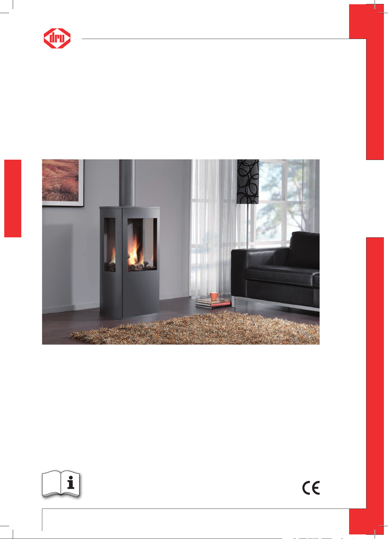
Trio RCE
G20/G25/G25.3 (natural gas)
English
Instructions for installation
Please retain this document carefully
959.064.04.EN
EN
Page 2

English
T R IO - I NS TR U C TI ON F OR I N S TA L LA T IO N
Contents
page
Preface 2
1. Introduction 3
2. CE Declaration 3
3. SAFETY 3
3.1 General 3
3.2 Regulations 3
3.3 Precautions / safety instructions during installation 3
4. Instructions 4
5. Removing the packaging 4
6. Installation 4
6.1 Regulations 4
6.2 Type of gas 4
6.3 Gas connection 4
6.4 Placement of the appliance 5
6.5 Flue gas discharge / combustion air supply system 5
6.6 Connecting gas 9
6.7 Setting the appliance 9
6.8 Placing the wood set 10
6.9 Panes 10
7. Wireless remote control 11
7.1 Receiver 11
7.2 Setting the communication code 12
7.3 Alternative operation 12
8. Final check 13
8.1 Gastightness 13
8.2 Gas pressure / pre-pressure 13
8.3 Ignition pilot and main burner 13
8.4 Flame picture 14
9. Maintenance 14
10 Delivery 14
11. Storingen 15
Appendix 1 Parts included with the delivery 18
Appendix 2 Technical data 19
Appendix 3 Parts 20
Appendix 4 Figures 21
Preface
DRU, a manufacturer of gas heating appliances, develops and produces products that comply with the highest quality, performance and safety requirements.
This guarantees that the user will be able to enjoy using his product for many years to come.
This appliance has a CE marking, which means that it complies with the essential requirements of the European gas
appliance directive.
As an installer, you must be competent in the field of atmospheric gas heating.
Two manuals are supplied with the appliance: the installation manual and the user manual. Installation and maintenance of the appliance should be performed by a professional certified expert with proven knowledge and demonstrable competence in this field. A professional expert takes all technical aspects such as heat output, gas connection
and electricity into account, as well as the flue gas discharge requirements.
The installation manual will give you the information you need to install the appliance in such a way that it will
operate properly and safely. If the installation instruction is not clear, national/local regulations must be observed.
This manual discusses the installation of the appliance and the regulations that apply to the installation. In addition,
you will find technical data for the appliance and information on maintenance, any malfunctions that might occur
and their possible causes.
Please carefully read and use this installation manual.
The following symbols are used in the manual to indicate important information:
Work to be performed
➠
!Tip
Suggestions and recommendations
2
Page 3
T R IO - I NS TR U C TI ON F OR I N S TA L LA T IO N
!Caution
You will need these instructions to prevent problems that might occur during installation and/or use.
Caution
You need these instructions to prevent re, personal injury or other serious damages.
After delivery, you should give the user manual and this installation manual to the user.
1. Introduction
The Trio is a freestanding atmospheric gas heating appliance. This version of the Trio is suitable for natural gas. It is
not possible to make the appliance suitable for a different type of gas by using a so-called conversion set.
The Trio is a closed appliance. A closed appliance does not extract the combustion air from the living environment,
but from outside. This is done through a combined flue gas discharge system / combustion air supply system. In
this concentric system the outer pipe serves as air supply and the inner pipe as flue gas discharge.
This system can be installed through the wall, or through the roof.
The concentric system can be supplied in the colour of the appliance.
The appliance is supplied with a wireless remote control that works on batteries.
2. CE Declaration
Internal precautions at the company will guarantee that appliances produced by DRU comply with the essential
requirements of the regulation concerning gas combustion appliances and the standards applied for that purpose.
This declaration will lose its validity if adjustments are made to the appliance, without prior written permission by
DRU. A copy of the CE test certificate can be downloaded via www.druservice.com.
English
Product: gas-fired heating appliance
Type: Trio RCE
Conformity assessment agency: Kiwa 0063
Applicable EC regulation: 2016/426/EU
Applied harmonized standards: NEN-EN-613; NEN-EN-613/A1
R.P. Zantinge
Managing director
Postbus 1021, 6920 BA Duiven
Ratio 8, 6921 RW Duiven
www.drufire.com
3. SAFETY
3.1 General
Caution
- Carefully read this chapter on safety, before you start performing installation or maintenance work;
- Please observe the general regulations and the precautions/safety instructions in this manual.
3.2 Regulations
Please install the appliance in accordance with the applicable national, local and constructional (installation) regulations.
3.3 Precautions / safety instructions during installation
Carefully follow the following precautions/safety regulations:
you should only install and maintain the appliance if you are a competent installer in the eld of atmospheric gas heating;
➠
do not make any changes to the appliance;
➠
only use the ue gas discharge / combustion air supply system supplied by DRU;
➠
place the appliance at a distance of at least 40 mm from the back wall;
➠
do not cover the appliance and the discharge material and/or do not wrap it in an insulation blanket or any other material;
➠
always place the appliance and/or the discharge pipes at a minimum distance of 500 mm from combustible objects or
➠
materials;
only ever use the supplied wood set;
➠
place the wood set exactly as described;
➠
make sure the pilot burner and the space around it is kept free;
➠
avoid dirt in gas pipes and connections;
➠
check the connections for gastightness before using the appliance;
➠
avoid blocking of the pressure equalization hatch on top of the appliance;
➠
check whether the pressure equalization hatch ts well onto the sealing surface;
➠
3
Page 4
English
T R IO - I NS TR U C TI ON F OR I N S TA L LA T IO N
do not ignite the appliance until it is fully installed;
➠
replace torn or broken panes.
➠
The appliance was designed for atmospheric and heating purposes. This means that all visible surfaces, including the
➠
glass pane, can become hotter than 100C°. It is recommended to always place a protective grating in front of the appliance when there are children, elderly people or handicapped persons in the same room as the appliance. If it is possible that vulnerable people are regularly present in the room with no supervision, a xed guard should be mounted
around the appliance.
Caution
- In case of broken or torn glass panes, the application may not be used.
- Protect the appliance against dust and moisture created during the building process!
4. Instructions
Observe the following items during installation in order to guarantee a proper and safe operation of the appliance:
avoid that the ignition cable runs over and/or alongside metal parts, in order to prevent weakening of the spark;
➠
avoid damaging the panes during removal/placing;
➠
clean the panes before you use the appliance, in order to prevent dirt from burning in the glass.
➠
5. Removing the packaging
Note the following items when removing the packaging:
remove all packaging materials
➠
Check the appliance for damages during transport;
➠
If necessary, contact DRU Service;
➠
Take the parts box and the wood set from the space behind the door at the bottom of the appliance.
➠
In appendix 1 / table 5 you can see which parts you should have after removing the packaging.
Remove both woodscrews from the bottom plate connecting the appliance to the platform.
➠
Caution
The glass pane(s) is/are made of a ceramic material. Very small irregularities in the glass pane(s) cannot be avoided, but
are within the required quality standards.
Caution
Keep plastic bags away from children.
Contact DRU Service if you do not have all the parts after you nished removing the packaging;
➠
Dispose packaging in accordance with local regulations.
➠
6. Installation
Read this manual carefully to ensure a proper and safe operation of the appliance.
!Caution
Install the appliance in the order described in this chapter.
6.1 Regulations
- Please install the appliance in accordance with the applicable national, local and constructional (installation)
regulations;
- Observe the regulations/instructions in this manual.
6.2 Type of gas
The type plate indicates for which type of gas, gas pressure and for which country this appliance is intended. The type
plate can be found behind the door on the back wall of the space at the bottom of the appliance.
Caution
- Check whether the appliance is suitable for the type of gas and the gas pressure used at the location.
- Do not make any changes to the appliance.
6.2.1 Reconstruction to different type of gas
If you want to convert this appliance into a different type of gas, please contact DRU’s service department and ask
what is possible. Reconstructions should only be performed by authorized gas installers.
6.3 Gas connection
Place a gas tap in the gas connection, close to the appliance.
Caution
- Make sure there is no dirt in the gas pipes and connections.
- No soldering may take place at the exible gas hose(s), as this could cause leaks.
4
Page 5
T R IO - I NS TR U C TI ON F OR I N S TA L LA T IO N
The following requirements apply to the gas connection:
- use a gas pipe with the correct dimensions, so that no pressure loss can occur:
- the gas tap must be approved (in the EU this will be the CE mark);
- you should always be able to reach the gas tap.
6.4 Placement of the appliance
Place the appliance as follows:
Caution
- Always place the appliance and/or the discharge pipes at a minimum distance of 500 mm from combustible objects
or materials;
Determine the location of the appliance; the dimensions can be found in Fig. 1, see Appendix 4;
➠
Provide a gas connection at the location. For details, see section 6.3;
➠
Make a duct for the ue gas discharge/combustion air supply system with the following diameters. For details, see
➠
section 6.5.
- Ø160 mm for a wall duct through incombustible material;
- Ø 250 mm for a wall duct through combustible material;
- Ø160 mm for a roof duct through incombustible material;
- Ø 250 mm for a roof duct through combustible material.
Place the appliance on its destined location.
➠
Caution
- Place the appliance at a distance of at least 40 mm from the back wall;
- Do not cover the appliance and the discharge material and/or do not wrap it in an insulation blanket or any other
material.
English
6.5 Flue gas discharge / combustion air supply system
6.5.1 General
The appliance is of the C11/C31/C91 type.
The appliance is connected to a combined flue gas discharge/combustion air supply system, hereafter referred to
as the concentric system.
The passage to the outside can be made with a wall duct (see section 6.5.2) or with a roof duct (see section 6.5.3).
If necessary, you can also use an existing discharge channel (see section 6.5.4).
Caution
- Only use the concentric system supplied by DRU (Ø100 / Ø150 mm). This system was tested in combination with the
appliance; DRU cannot guarantee a proper and safe operation of other systems and cannot accept liability for these
systems;
- For connecting to an existing chimney ue you should only use the installation set supplied by DRU.
The concentric system is constructed from (the discharge stump of) the appliance.
If structural circumstances require that the concentric system is placed first, the appliance can later be connected
with a telescopic pipe piece.
!Tip
DRU does not recommend placing the telescopic piece, because this visible pipe piece cannot be supplied in colour
and does not really combine well with the appliance.
6.5.2 Application with wall duct
6.5.2.1 Construction of concentric system with wall duct
The concentric system with wall duct has to comply with the following conditions (see Appendix 4, Fig. 2):
- First, a concentric pipe of at least 1 meter should be connected vertically to the appliance;
- The total vertical pipe length can have a maximum of 4 meters;
- On the vertical part a bend of 90° is connected;
- The total horizontal pipe length can have a maximum of 3 meters (wall duct excluded).
Under these conditions you should not install the restrictor slide; the air inlet guide will not be placed.
6.5.2.2 Placing concentric system with wall duct
Place the concentric system as follows:
Build the system up from (the connection stump of) the appliance.
➠
Caution
- Maintain a distance of at least 50 mm between the outside of the concentric system and the walls and/or the ceiling;
- Use heat-resistant isolation material when passing through combustible material;
- The rosette (mounting inner plate) of the wall duct is too small to seal the Ø 250 mm opening when passing through
combustible material. That is why you should rst apply a suciently large heat-resistant intermediate plate to the
wall. Then, the rosette is mounted on the intermediate plate.
!Caution
Some heat-resistant isolation materials contain volatile components that will spread an unpleasant smell for a pro-
longed time; these are not suitable.
5
Page 6

English
T R IO - I NS TR U C TI ON F OR I N S TA L LA T IO N
Remove the top plate from the appliance; this plate is loose;
➠
Remove the cover plate by unscrewing the 2 parkers (see Appendix 4, Fig. 2);
➠
Place a lacquered pipe piece on the appliance;
➠
Apply a lacquered clip binding with silicon sealing ring onto the connection between appliance and pipe piece;
➠
Ret the cover plate with the 2 parkers;
➠
Place the top plate carefully onto the appliance, so that the lacquered pipe piece will not be damaged;
➠
If necessary, connect the vertical (lacquered) concentric pipe pieces;
➠
Connect the lacquered bend;
➠
If necessary, connect the horizontal (lacquered) concentric pipe pieces;
➠
On each connection, apply a (lacquered) clip binding with silicon sealing ring;
➠
Use a parker to x the clip binding to the pipe on locations that are unreachable after installation;
➠
Attach the concentric system with sucient fastening brackets, so that the weight is not resting on the appliance.
➠
Observe the following;
- Place the rst fastening bracket 0.5 metre from the appliance, at the most.
- Place a fastening bracket maximum 0.1 metre from each bend, if the bends are more than 0.25 metre away from
each other. If two bends are closer to one another than 0.25 metre, 1 fastening bracket between these bends will be
sucient.
- At least every 1 metre, place a fastening bracket at slanted and horizontal sections.
- At least every 2 metres, place a fastening bracket at vertical sections.
Determine the remaining length of the wall duct;
➠
Make sure the wall duct has the right dimensions.
➠
!Caution
- Make sure that the right insertion length is maintained;
- Place the wall duct with the groove/folded seam at the top;
- Make sure the horizontal concentric pipe pieces are sloping towards the wall duct, in order to prevent rain water
from entering.
Mount the rosette (mounting inner plate); if necessary, on a heat resistant intermediate plate when passing through
➠
combustible material;
Attach the wall duct from the outside with four screws in their respective holes.
➠
6.5.3 Application with roof duct
6.5.3.1 Construction of concentric system with roof duct
The concentric system with roof duct has to comply with the following conditions:
- The construction of the chosen system has to be allowed. (See the procedure described below);
- First, a concentric pipe of at least 1 meter should be connected vertically to the appliance.
Depending on the construction, the appliance is set by means of the baffle and/or the air inlet guide.
In the following procedure you can see how the allowability of a concentric system can be determined and which
settings are needed.
Determine the following data:
➠
1) The number of bends required (no distinction is made between 45° and 90° bends);
2) The total number of meters of horizontal pipe length;
3) The total number of meters of vertical and/or sloping pipe length.
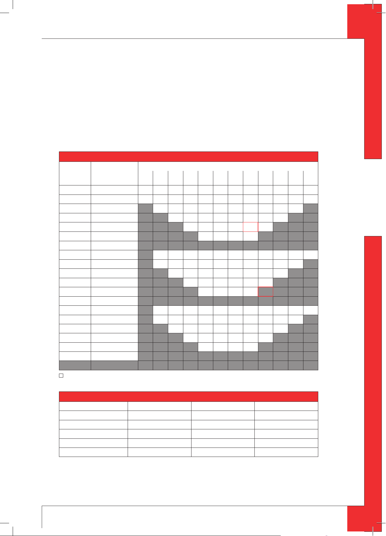
These data will help you determine whether the concentric system is allowed by using Table 1 for G25/G25.3 and
Table 3 for G20.
In Table 2 you can read for G25/G25.3 and G20 which setting is required for the appliance.
Follow the procedure described below:
In the rst 2 columns of Table 1/Table 3, search the number of bends required and the total horizontal pipe length:
➠
In the 3rd column of Table 1/Table 3, search the total vertical and/or sloping pipe length.
➠
If you end up in a box with the letter A, B, C, D or E, the concentric system chosen by you is allowed.
Use Table 2 to determine which conditions apply for the bae and/or the air inlet guide (for placing/setting see section 6.7).
➠
Examples G25/G25.3
To clarify, we will give 2 examples for gas G25/G25.3, to determine the allowability of a concentric system and the
conditions for setting the appliance.
In Table 1 the route to be followed is indicated by arrows. The result is indicated by an underlined letter (= allowed)
or a dash “-“ (= not allowed).
6
Page 7
T R IO - I NS TR U C TI ON F OR I N S TA L LA T IO N
Example 1
1) 2 bends
2) 3 meters horizontal
3) 8 meters vertical/sloping
→ Construction of this concentric system is allowed.
→ Situation D applies for setting the appliance
Example 2
1) 3 bends
2) 4 meters horizontal
3) 9 meters vertical/sloping
→ Construction of this concentric system is not allowed.
Table 1: Relation construction concentric system / setting appliance
G25/G25.3 total number of
meters horizontal
pipe length
no bends 0 B C D D D E E E E E E E
2 bends 0 A A B C D D D E E E E E
1 A A B C D D D E E E
2 A A B C D D D E
3 bends 0 A A B C D D D E E E E
1 A A A B C D D D D D
2 A A A B C D D D
3 A A A B C D
5
4 bends 0 A A A B C D D D E E E
1 A A A A B C D D D E
2 A A A A B C D D
3 A A A A B B
4 A A A A
5 bends -
3 A A B C D D
4 A A B C
5
4 A A A B
5
total number of meters vertical and/or sloping pipe length
1 2 3 4 5 6 7
8 9
10 11 12
English
n = construction is not allowed
Table 2: Conditions for setting the appliance
Situation Air inlet guide Baffle Distance restriction
A NO YES 65 mm
B NO YES 50 mm
C NO YES 40 mm
D NO YES 33 mm
E YES YES 33 mm
7
Page 8
English
T R IO - I NS TR U C TI ON F OR I N S TA L LA T IO N
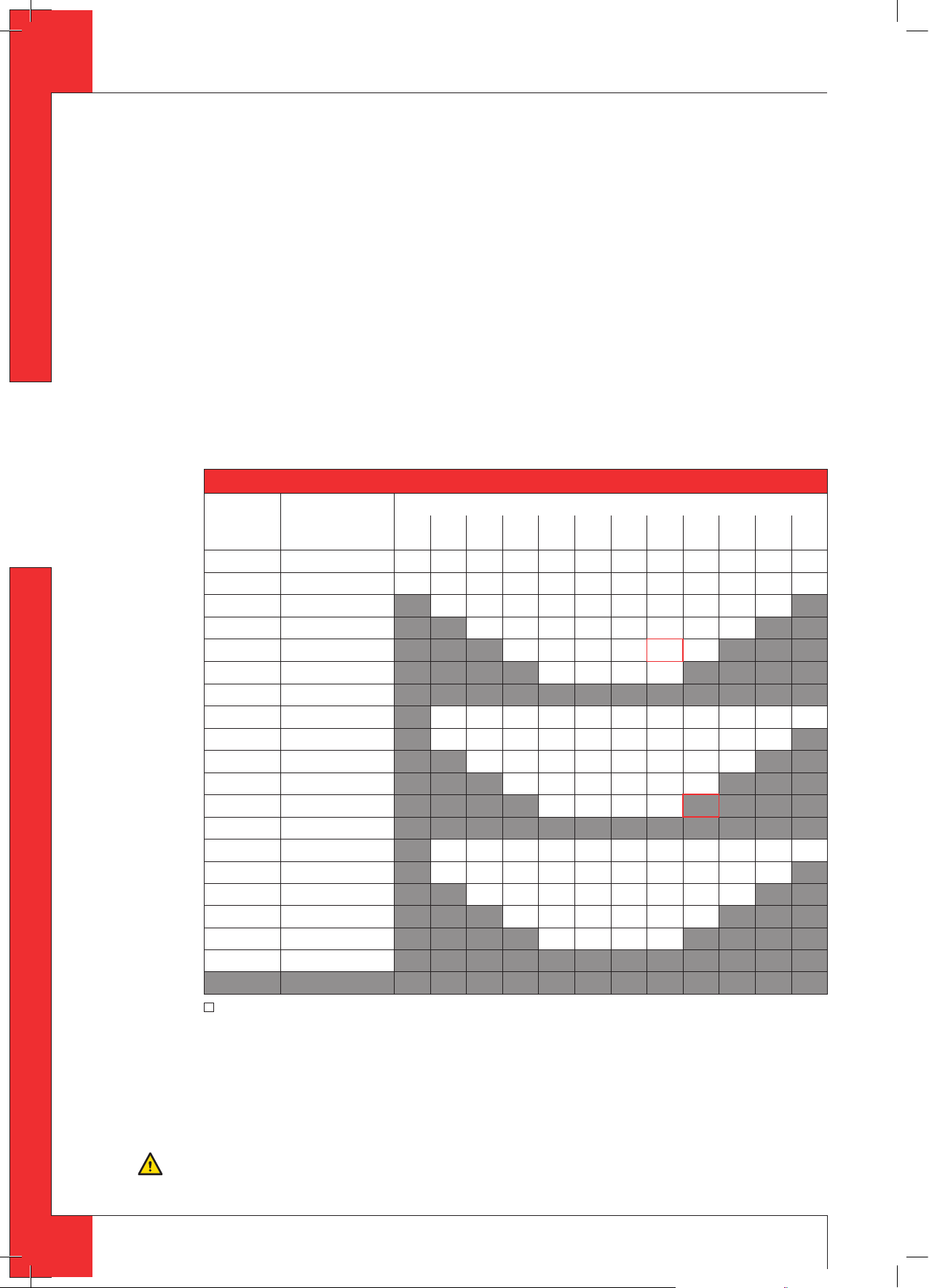
Examples G20
To clarify, we will give 2 examples for Gas 20, to determine the allowability of a concentric system and the conditions
for setting the appliance.
In Table 3 the route to be followed is indicated by arrows. The result is indicated by an underlined letter (= allowed)
or a dash “-“ (= not allowed).
Example 1
1) 2 bends
2) 3 meters horizontal
3) 8 meters vertical/sloping
→ Construction of this concentric system is allowed.
→ Situation C applies for setting the appliance
Example 2
1) 3 bends
2) 4 meters horizontal
3) 9 meters vertical/sloping
→ Construction of this concentric system is not allowed.
Table 3: Relation construction concentric system / setting appliance
G20
no bends 0 B C C C C E E E E E E E
2 bends 0 A A B C C C C E E E E E
1 A A B C C C C E E E
3 bends 0 A A B C C C C E E E E
1 A A A B C C C C E E
2 A A A B C C C C
3 A A A B C C
5
4 bends 0 A A A B C C C C E E E
1 A A A A B C C C C E
2 A A A A B C C C
3 A A A A B C
4 A A A A
5 bends -
total number of
meters horizontal
pipe length
2 A A B C C C C E
3 A A B C C C
4 A A B C
5
4 A A A B
5
total number of meters vertical and/or sloping pipe length
1 2 3 4 5 6 7
8 9
10 11 12
n = construction is not allowed
6.5.3.2 Placing concentric system with roof duct
The roof duct can end in a sloping and a flat roof.
The roof duct can be supplied with an adhesive plate for a flat roof or with a universally adjustable tile for a sloping
roof.
Place the concentric system as follows:
Build the system up from (the connection stump of) the appliance.
➠
Caution
- Maintain a distance of at least 50 mm between the outside of the concentric system and the walls and/or the ceiling;
- Use heat-resistant isolation material when passing through combustible material.
8
Page 9

T R IO - I NS TR U C TI ON F OR I N S TA L LA T IO N
!Caution
Some heat-resistant isolation materials contain volatile components that will spread an unpleasant smell for a pro-
longed time; these are not suitable.
Remove the top plate from the appliance; this plate is loose;
➠
Remove the cover plate by unscrewing the 2 parkers (see Appendix 4, Fig. 3);
➠
Place a lacquered pipe piece on the appliance;
➠
Apply a lacquered clip binding with silicon sealing ring onto the connection between appliance and pipe piece;
➠
Ret the cover plate with the 2 parkers;
➠
Place the top plate carefully onto the appliance, so that the lacquered pipe piece will not be damaged;
➠
Connect the horizontal (lacquered) concentric pipe pieces and, if necessary, the bends;
➠
On each connection, apply a (lacquered) clip binding with silicon sealing ring;
➠
Use a parker to x the clip binding to the pipe on locations that are unreachable after installation;
➠
Attach the concentric system with sucient fastening brackets, so that the weight is not resting on the appliance.
➠
Observe the following;
- Place the rst fastening bracket 0.5 metre from the appliance, at the most.
- Place a fastening bracket maximum 0.1 metre from each bend, if the bends are more than 0.25 metre away from
each other. If two bends are closer to one another than 0.25 metre, 1 fastening bracket between these bends will be
sucient.
- At least every 1 metre, place a fastening bracket at slanted and horizontal sections.
- At least every 2 metres, place a fastening bracket at vertical sections.
Fasten a roof terminal with anchor cables, if it protrudes more than 1,5 metres above the terminal.
➠
Determine the remaining length of the roof duct;
➠
Make sure the roof duct has the right dimensions.
➠
!Caution
Make sure that the right insertion length is maintained.
Connect the roof duct to the concentric pipes.
➠
!Caution
- Make sure that the universal tile ts well with the surrounding tiles;
- Make sure that the adhesive plate ts well onto the at roof.
English
6.5.4 Connection of existing chimney flue
It is possible to connect the appliance to an existing channel.
A flexible SS pipe is placed in the chimney for discharging flue gases. The surrounding space is used to supply
combustion air.
The following requirements apply when connecting to an existing chimney flue:
- only allowed when used in combination with the special DRU chimney installation set.
The installation regulation is also supplied;
- the dimensions should be at least 150 x 150 mm;
- the vertical length has a maximum of 12 meters;
- the horizontal length has a maximum of 3 meters;
- the existing chimney flue has to be clean;
- the existing chimney flue has to be closed.
For adjusting the appliance, the same conditions/instructions apply as for the concentric system described above.
6.6 Connecting gas
Use the following procedure when connecting the gas, see section 6.3 Gas connection:
If necessary, blow through the gas pipe;
➠
Connect the gas pipe with gas tap to the gas control block.
➠
!Caution
- You can nd the gas control block behind the door in the space at the bottom of the appliance;
- Do not turn the gas tap when connecting the gas pipe.
Bleed the gas pipe.
➠
6.7 Setting the appliance
The appliance has to be set in such a way that is works correctly in combination with the discharge system.
For that purpose it is possible to install a baffle and/or an air inlet guide. For the conditions, see section 6.5.2.1,
for application with wall duct and section 6.5.3.1, Table 2, for application with roof duct.
6.7.1 Baffle (R)
!Caution
The restrictor slide should be placed in the correct manner. Therefore, accurately observe the instructions
The baffle (R) is supplied separately.
Follow the procedure below when placing the baffle:
Remove the front pane as indicated in section 6.9.1;
➠
9
Page 10

English
T R IO - I NS TR U C TI ON F OR I N S TA L LA T IO N
Place the bae (see Appendix 4, Fig. 4);
➠
Use the template supplied to set the distance of the restriction (see Appendix 4, Fig. 5) as follows:
➠
- A distance of 33 mm means that the bae is closed to a maximum level;
- A distance of 40, 50 and 65 mm is set by using a template.
Fix the bae by using the socket cap screw (S).
➠
6.7.2 Air inlet guide (L)
The air inlet guide (L) is supplied separately.
Follow the procedure below for installing the air inlet guide (see Appendix 4, Fig. 6):
Remove the front pane as indicated in section 6.9.1;
➠
Remove the tray surrounding the burner (M) from the appliance;
➠
Place the air inlet guide;
➠
Place the tray surrounding the burner (M) back in the appliance.
➠
!Caution
Do not throw away the air inlet guides, you may need them in the future.
6.8 Placing the wood set
The appliance is supplied with a wood set.
Caution
Strictly observe the following instructions to prevent unsafe situations:
- only ever use the supplied wood set;
- place the wood set exactly as described;
- make sure the pilot burner and the space around it are kept free from objects (
- make sure that the slot between the burner tray and the tray surrounding the burner is kept free from objects.
- make sure that the vermiculite’s ne dust does not get on the burners.
see Appendix 4, Fig. 7);
6.8.1 Wood set
The wood set consists of vermiculite (see Appendix 4, Fig. 8), chips (see Appendix 4, Fig. 9) and a number of blocks.
Fill the burner tray with vermiculite; equally spread the vermiculite (see Appendix 4, Fig. 14).
➠
!Caution
- You can inuence the ame image by moving the vermiculite, yet
- the burner deck has to remain covered with vermiculite in order to prevent that the life expectancy of the burner is reduced
Fill the tray around the burner with chips; equally spread the chips.
➠
Caution
Do NOT place chips over the slot, around the burner.
Identify blocks A up to F by using Fig. 10, see Appendix 4.
➠
!Tip
Use the burn stains on the blocks for identication.
First place blocks A and B (see Appendix 4, Fig. 11).
➠
Caution
- Place block A in such a way that the pilot ame and ame opening are not covered. Fig. 11, see Appendix 4, shows how
it should be done, and
Then place blocks C up to F (see Appendix 4, Fig. 13).
➠
Caution
The logs should not completely cover the burner pattern, because:
- the main burners will not ignite properly; which could result in unsafe situations;
- the appliance will become lthy more quickly, as a result of soot;
- the ame picture will be aected.
Fig. 12, see Appendix 4, shows how it should not be done
6.9 Panes
6.9.1 Front pane
After placing the wood set you can place the front pane as described below.
!Caution
- Avoid/remove ngerprints on the pane, as they will burn into the glass.
- Avoid damages when removing/placing the glass pane.
- Make sure the sealing tape at the edges of the glass pane is not damaged during removal.
10
6.9.1.1 Removing the front pane
When removing the front pane, you should observe the instructions below; (see Appendix 4, Fig. 15 to 18)
Open the door;
➠
Unscrew the 6 parkers of the glass strip at the sides by using the socket spanner supplied;
➠
Remove the glass strips;
➠
Unscrew the 3 parkers of the upper glass strip;
➠
Hold the pane and remove the upper glass strip;
➠
Remove the pane from the slot at the underside.
➠
6.9.1.2 Placing the front pane
Placing the front pane will take place in reverse order of the removal procedure described above.
!Caution
Do not screw the parkers on too tight, to prevent breaking and/or slipping: tight=tight.
Page 11

T R IO - I NS TR U C TI ON F OR I N S TA L LA T IO N
6.9.2 Side panes
The side panes should be removed in case of torn or broken panes.
6.9.2.1 Removing the side pane
Follow the steps below for removing:
Carefully remove the top plate from the appliance, so that the lacquered pipe piece will not be damaged. The top plate
➠
is loose;
Slide the housing upwards at the side (see Appendix 4, Fig. 19);
➠
Remove this part of the housing;
➠
Unscrew the 3 parkers at the top by using the socket spanner;
➠
Hold the pane and remove the glass strip;
➠
Remove the pane from the slot at the underside.
➠
6.9.2.2 Placing the side pane
Placing the side pane will take place in reverse order of the removal procedure described above.
!Caution
Do not screw the parkers on too tight, to prevent breaking and/or slipping: tight=tight.
7. Wireless remote control
The appliance is supplied with a wireless remote control.
Ignition, controlling the flame height and switching off are performed by a remote control that operates a receiver
in the control box.
User Manual, chapter 4, Command/control, describes the operation of the appliance including the way the remote
control works.
English
!Caution
Do not ignite the appliance before the gas and discharge connections have been fully installed, rst observe the pro-
cedure described in chapter 8.3.
Below, we will describe how the receiver is connected.
7.1 Receiver
The receiver should be connected to the appliance, before the batteries are installed.
Follow the procedure below (see Appendix 4, Fig. 21):
Slide the brown plug of the connecting cable onto the back of the receiver’s printed circuit board.
➠
Connect the white plug to the gas control block.
➠
!Tip
The plugs have dierent sizes that correspond with the connectors.
Connect the cables of thermocouple 1 to the receiver; (see Appendix 4, Fig. 21, arrow B).
➠
!Tip
- The size of the eye corresponds with the size of the screw;
- The colours of eye and screw also correspond.
Connect the ignition cable to the receiver; (see Appendix 4, Fig. 21, arrow A).
➠
Connect power:
➠
a) When using batteries, see section 7.1.1 below;
b) When using an adapter:
- connect it to the receiver; (
- insert the plug into the wall socket.
Place the receiver in the control box, as indicated on Fig. 22 (o), see Appendix 4.
➠
Bend the antenna out of the clips; see Appendix 4, Fig. 21, arrow D and Fig. 22.
➠
Set the antenna straight.
➠
see Appendix 4, Fig. 21, arrow C);
!Caution
- Do not place the antenna too close to the ignition cable and/or metal parts (for the correct position, see Appendix 4,
Fig. 22);
- Do not place the ignition cable over and/or along metal parts: this will weaken the spark;
- Do not lay the ignition cable over the receiver. this could damage the receiver;
- Avoid dust on or in the receiver: cover it when performing work.
11
Page 12

English
T R IO - I NS TR U C TI ON F OR I N S TA L LA T IO N
7.1.1 Placing / replacing the batteries
Follow the procedure below when placing the batteries:
Open the door of the stove.
➠
Pick up the receiver.
➠
Slide the cover o.
➠
Place or remove the 4 penlite (AA type) batteries.
➠
!Caution
- Avoid a short circuit between the batteries and metal objects/parts;
- Observe the “+” and “-” poles of the batteries and the holder;
- Use alkaline batteries.
Slide back the cover.
➠
Place back the receiver.
➠
!Caution
Batteries are regarded as “small chemical waste” and may therefore not be disposed with the household rubbish.
7.2 Setting the communication code
Prior to putting the application into operation, a communication code must be set between the remote control
and the receiver. If the receiver or the remote control are replaced, a new code will have to be set.
Follow the procedure described below:
If necessary, place the batteries in the receiver’s battery holder; see section 6.1.1.
➠
If necessary, place the 9V block battery in the remote controle; see User Manual.
➠
Hold down the reset button on the receiver, until you hear two consecutive sound
➠
see Appendix 4, Fig. 24).
signals (
After the second, longer signal, let go of the reset button.
➠
Press the ‘small ame’ button on the remote control for 20 seconds, until you hear two short sound signals: this is the
➠
conrmation of a good communication.
Small Flame
Large Flame
7.3 Alternative operation
Appliances made with an electronic ignition and radio remote control can be connected to an alternative external
control system (e.g. Domotics). For this purpose, there are 4 connection points at the side of the receiver (see Ap-
pendix 4, Fig. 20). For connecting an external control unit, you will need a “Domotics connection cable for GV60”.
Consult DRU’s service website.
The following contacts are possible:
- Ignition: connect both contacts 1 + 3, for one second (if there is a 2nd thermocouple, the appliance should burn
at full power for at least 20 sec. before the required position can be chosen).
- Flame high(er): briefly close contact 1 once per step, or 12 seconds for the highest position.
- Flame low(er) until switch-off (pilot flame remains on): briefly close contact 3 once per step, or 12 seconds for the
lowest position.
- Completely switching off the appliance (pilot flame included): close all three contacts 1 + 2 + 3, for one second.
The appliance will always continue to respond to the radio remote control supplied with it. The external control
system is able to use one of the two modes of this remote control.
1. Manual mode
This mode of the remote control is passive and will not take any action unless it is operated. The external control
system is able to control the functions for high/low position, ignition and switching off.
!Tip
If the external control system has an intelligent clock function and/or thermostat function, the remote control sup-
plied with the appliance should have the manual mode in order to prevent interruption of these functions.
2. Clock/thermostat mode
This mode of the remote control is active and will be responsible for the clock function and thermostat function.
The external control system is able to control the functions for high/low position, ignition and switching off.
12
!Tip
- If the appliance is switched o (the pilot ame included) manually or by one of the safeguards, ignition of the appliance will be blocked for a period of 3 minutes for reasons of safety.
- If it is no longer possible to operate the appliance with the external control system, you must switch it o and then
switch it on again with the supplied remote control.
Page 13

T R IO - I NS TR U C TI ON F OR I N S TA L LA T IO N
8. Final check
In order to check whether the appliance is working properly and safely, you must perform the following checks before
the appliance is used.
8.1 Gastightness
Caution
All connections must be gastight.
!Caution
The gas control block can be subjected to a maximum pressure of 50 mbar.
Check the connections for gastightness.
➠
8.2 Gas pressure / pre-pressure
The burner pressure is set at the factory; see type plate. It is not necessary to check the burner pressure.
The pre-pressure in house installations, however, should be checked, as they can vary.
Check the pre-pressure; see Appendix 4, Fig. 23 for the measuring nipple on the gas control block;
➠
Contact the gas company if the pre-pressure is not correct.
➠
8.3 Ignition pilot and main burner
For igniting the pilot and main burner, see the User Manual, chapter 4, Operation.
Caution
Always wait 5 minutes after the pilot ame has gone out, before you re-ignite the appliance.
8.3.1 First ignition of the appliance after installation or adjustments
!Caution
After installation, or after work has been performed, you should ignite the appliance for the rst time without the glass
window. If necessary, bleed the gas pipe.
Follow the procedure described below:
If required, remove the glass window;
➠
Start the ignition procedure according to chapter 4 in the User Manual;
➠
If the pilot ame does not ignite:
➠
- repeat the ignition procedure until the pilot burner ignites;
- consult the malfunction search diagram (Chapter 11) if this does not happen after a few attempts;
After igniting the pilot ame, the main burner will ignite during the ignition procedure;
➠
Check whether the main burner continues to burn;
➠
If the main burner does not continue to burn:
➠
- repeat the ignition procedure until the main burner continues to burn
- consult the malfunction search diagram (Chapter 11) if this does not happen after a few attempts;
Switch o the appliance;
➠
Clean the glass pane before using it for the rst time, as described in the user manual.
➠
Then mount the glass pane as described in section 6.9.
➠
Repeat the ignition procedure a few times and perform the checks described in chapter 8.3.2;
➠
From now on, the pilot ame should ignite smoothly.
➠
Clean the glass pane after burning for the rst time, as described in the user manual.
➠
English
!Caution
- During the ignition process, you are not allowed to operate control button B on the gas control manually.
- Always wait 5 minutes after the pilot ame has gone out, before you re-ignite the appliance.
- You are not allowed to turn the pilot ame lower by using the settings on the gas control.
8.3.2 Main burner
!Caution
- The pilot burner should ignite the main burner within a couple of seconds, and without popping.
- The main burner(s) must cross the full burner smoothly and without popping and continue to burn.
Check operation of the main burner from a cold condition (pilot ame o):
➠
After opening the gas valve, the main burner should burn within a few seconds.
➠
!Tip
When the gas valve is opened, the motor will start to run; this is audible.
The ame picture and a good ame transfer can only be properly judged if the glass window is installed.
Use the malfunction search diagram (Chapter 11) if the ignition of the main burner does not comply with the abovementioned requirements.
13
Page 14

English
T R IO - I NS TR U C TI ON F OR I N S TA L LA T IO N
8.4 Flame picture
The flame picture can only really be assessed when the appliance has been burning for several hours. Volatile components from paint, materials, etc., which evaporate in the first hours, will affect the flame picture.
Check whether the ame picture is acceptable.
➠
Consult the malfunction search diagram (Chapter 11) if the ame picture is not acceptable.
➠
9. Maintenance
Once a year the appliance should be checked, cleaned and, if necessary, repaired by a competent installer in the field
of atmospheric gas heating.
Check at least whether the appliance is working properly and safely.
Caution
- Close the gas tap when performing maintenance work;
- Check the gastightness after repair;
- After replacing the thermocouple you should rst tighten the swivel of the gas control block by hand and then give
it another quarter turn with a suitable spanner.
- SS-absolutely do not clean the concentric system (internally) with a steel brush or metal sponge, for example. This
will damage the oxide skin and could lead to leaks in the system as a result of pitting corrosion.
If required, clean the following components:
➠
- the pilot ame burner;
- the combustion room;
- the panes.
!Caution
Only clean a glass pane once it has reached room temperature.
!Caution
- Avoid damage to the glass pane(s).
- Avoid/remove ngerprints on the glass pane(s), as they will burn into the glass.
- Clean the glass pane(s) as described in the user manual.
- Regularly remove accumulated dirt, as it can burn into the glass.
- Do not use the appliance when a glass pane is broken and/or cracked, until it has been replaced as described from
section 6.9
Caution
- If necessary, place back the wood set correctly; see section 6.8.
Inspect the ue gas discharge / combustion air supply system;
➠
!Caution
You must always perform a nal inspection.
Perform a check as described in chapter 8.
➠
Parts requiring replacement can be obtained from your supplier.
10 Delivery
You must explain to the user how he should operate the appliance. Yo u should instruct her/him for instance on using
the appliance for the first time, the operation of the remote control, annual maintenance.
Caution
- Tell the user to close the gas tap immediately in case of malfunctions/bad performance and contact the installer in
order to prevent dangerous situations;
- Indicate the location of the gas tap;
- Point out the precautions in the user manual against unintended ignition by other wireless remote controls such as
car keys and garage door openers.
Instruct the user about the appliance and the remote control.
➠
When the appliance is started for the rst time, point out that
➠
- when the appliance is stoked up for the rst time, volatile components evaporate from paint, materials, etc.;
- when evaporating the appliance should preferably be set at the highest level;
- the room should be well ventilated.
Give the user manual and installation manual to the user (the installation manual should be kept near the appliance).
➠
14
Page 15

T R IO - I NS TR U C TI ON F OR I N S TA L LA T IO N
11. Storingen
Malfunction search diagram atmospheric gas-red heating appliance with electronic ignition: Starting up cycle.
Start
1.01
Does receiver beep?
no
1.02
Receiver
- Batteries missing or empty.
Replace by 4x AA.
After replacing batteries: short
beep. No beep: receiver defective.
Replace by new one.
- Replace rechargeables by alkaline
batteries.
- Communication code between
remote and receiver has to be
(re)set:
- Press reset button on receiver
until brief beep, followed by long
beep.
- Release reset button and press
‘ame low’ button on remote
within 20 seconds. Then 2 short
beeps and brief noise of
servomotor to conrm that
communication code was set
succesfully.
yes
1.03
One long 5 second beep, (possibly
preceded by 7 short beeps).
yes no
1.04 Controleer:
All appliances
- 8 wire cable between receiver
and gas control not connected,
poor contact or one wire loose
in connector (check by pulling
wire by wire).
- Wiring of thermocouple circuit
interrupted, or poor contact.
Check thermocouple,
thermocouple interrupter and
wiring.
Sie box 2.05.
- Microswitch on gascontrol
defective.
1.05
no yes
Short sound signals, 1 sec after
each other, followed by the
clicking noise of the gasvalve
opening.
1.06
3 swift beeps 1 sec after each
other when motor turns or 3
brief short beeps within 1 sec
at end of ignition cycle.
yes
1.07
Replace batteries
Measure battery voltage:
<5.5V: replace preventative.
<4.8V: appliance works no
longer. Replace batteries.
Turn two pages backwards
and continue with box 2.01.
English
Remote control
- Battery 9V empty (see indication
on display).
Several
- After switching o/going out the
remote set is locked for 120 sec.
(older versions 60 sec).
Wait 2 minutes before reigniting.
15
Page 16

Fires with electronic ignition, fault nding: Ignition and burning
Start
T R IO - I NS TR U C TI ON F OR I N S TA L LA T IO N
2.01 Can pilot be lit?
no
2.02 Sparking?
yes
2.03 Only one spark?
no
2.04 Check:
Receiver
- Replace missing, weak or
rechargeable batteries (not
enough power to open
thermoelectric valve).
Presence of gas on pilot burner
Check pilot on presence of gas at
normal ignition cycle or in Manual
English
Mode (turn oval knob on gas control
to MAN and keep safety shut o
valve opened with a screwdriver) and
ignite pilot with a lighter.
- Pilot ame not on: Step 1.
- Pilot ame on: Step 2.
Step 1: Pilot has no gas
Check:
- Gas tap open?
- Gas at gas control (line
pressure at measuring point on
gas control).
- Gas owing out of gas control?
(by loosening pilot tube at gas
control).
If not: check adjustment screw
pilot ame (under black cover):
sealing not to be broken.
Sealing broken: screw should
be fully open.
- Blocking of pilot tube (kink or
dirt).
- If this does not help: replace
gas control.
Step 2: Pilot has gas, but no
ignition
- Electrode with 90° bended tip:
bend tip 1 mm higher.
- Spark too weak (thin and
reddish).
Act as if ‘no spark’ in box 2.05
and perform actions described
for ignition cable and ignition
electrode.
- Pilot ame too weak (dirty).
Remove injector (remove
gland nut and the pilot tube).
See that it does not fall away.
Clean with compressed air.
Rectify. Retry.
yes
no
2.03a
- Loosen and retighten
earthing screw on gas
yes
control.
- If this does not work:
replace receiver.
2.05 Check:
Ignition cable
- Present and connected.
- Being free from metal parts or
concrete.
- Too long: cut away all
excessive length at receiver
end, and reconnect.
- Shorting out to earth: replace
ignition cable.
- Spark in wrong position:
- slide rubber sleeve on
ignition cable over ceramic of
electrode.
- Replace electrode if
neccessary.
Ignition electrode
- Straight electrode:
- oxidation (roughen electrode
with le or sand paper);
- position (4 mm from pilot
burner).
- Cracks in ceramic (not always
visible): replace electrode.
Starting procedure
After switching o/going out the
remote is locked for 120 sec. (older
versions 60 sec).
Wait 2 minutes before reigniting..
2.06 Pilot can be lit.
Does it stay alight?
yes yes
no
2.07 Pilot out when servomotor
starts
to run? Check the thermocouple
system.
- Measure thermocouple
voltage in mV just after
servomotor starts to run and
the voltage goes down.
- Measure between red dot on
receiver and earth point on
gas control (see Appendix 4,
Fig. 25).
- 0 mV
- 2-3 mV
- 3-5 mV
- 6 mV and higher
- Requirement: after
rectication actions
thermocouple voltage should
be 6 mV at least, just after
motor starts running!
Voltage 0 mV
- Thermocouple defective.
Check by replacing or
measuring voltage at end
whilst heating (tip: with a
lighter).
- Short circuiting or
interruptions in circuit:
Check:
- thermocouple tight in
interruptor;
- interruptor tight in gas
control;
- black wires (yellow/red end)
connected to interruptor +
receiver;
- interruptor (mount
thermocouple directly in gas
control and ignite in Manual
Mode (see 2.04).
If pilot stays on: interruptor
defective.
Voltage 2-3 mV
- Check pilot ame.
Too small:
- pilot dirty.
Clean up (see 2.04).
- check for pilot gas tube
tightness;
- pilot tube kinks or dirt inside;
- line pressure too low.
- Tip: thermo couple not in
(correct!) pilot ame.
Bend into ame.
Voltage 3-5 mV
- Appliance may work, but is
too critical.
Perform actions as described
for 2-3 mV.
Voltage 6 mV and higher
Voltage OK, so dierent cause.
- Receiver defective. Check by
dismounting black-red and
yellow control cables from
receiver and link together.
Ignite re in Manual Mode
(see 2.04). Pilot stays on:
receiver defective.
- Gas control defective if
receiver is not defective.
Replace gas control.
2.08 Does main burner ignite
immediately?
no no
2.09 Ignition procedure
- Oval knob on gas control is
on “MAN”. Set to “ON” and
restart.
Retarded ignition of main
burner(s)
Gas to main burner opens ca. 3-5
seconds after servo motor,
operating the gas valve, starts
running (sound of motor!). After
this the main burner is to ignite (at
least partially) within 10 seconds
and not with a rm noise WHOOF.
If not: no or delayed cross lighting
of main burner.
Hazardous situation.
Stop ignition procedure straight
away and rst check for:
- Position of logs or pebbles.
- Burner holes (locally)
blocked.
Remove vermiculite dust.
- Vermiculite missing.
- Chips on burner.
- Vermiculite not distributed
evenly across burner(s).
2.10 Do(es) main burner(s)
ignite smoothly and across
its/their full length after rst
ignition by pilot burner?
2.11 No proper cross lighting
of main burner(s).
- Go to box 2.09 and take
actions act as described
for ‘retarded ignition of
main burner’.
yes
16
Page 17

T R IO - I NS TR U C TI ON F OR I N S TA L LA T IO N
yes no yes yes
2.12 Does main burner go out
after ‘some time’?
yes
2.13 Check
Gas supply
- Supply pressure does not
drop away as main burner (or
other appliance) lights,
causing pilot ame to shorten.
- Burner pressure (too high or
too low).
Flames instable (suocating, lack
of air).
Dancing ames on burner.
Lack of combustion air. Check:
- ue system permissible;
- proper ue terminal used,
make should be ‘DRU’;
- terminal correctly sited on
roof or wall relative to
obstructions;
- integrity of ueing system (no
interruptions, not barred,
cobwebs);
- air inlet guides;
- ue restrictor/damper;
- throttle rings.
See manual for specic
requirements.
Pilot burner
- Pilot burner dirty. Weak pilot
ame being drawn away by
ames main burner.
Clean with compressed air.
See 2.04.
2.14 Is ame picture OK?
no
2.15 Check
Flames: too low
- Supply pressure does not
drop away as main burner or
other appliances in the
building light, causing ames
to shorten.
- Burner pressure (too low).
- False air: Check soundness
glass window gasket/
soundness of the connection
of the glass panes of
two/three sided appliances
(no slots allowed).
Flames: too high
- Line pressure.
- Burner pressure.
Flames: no even distribution or
out on part of the burner(s)
- Position of logs or pebbles.
- Burner holes (locally) blocked.
Remove vermiculite dust.
- Vermiculite not distributed
evenly across burner(s).
- Adjustment of throttle ring(s).
Flames: too blue/too yellow or
sooting
- Air inlet guides.
- Flue restrictor/damper.
- Adjustment of throttle ring(s).
Flames: suocating: lack of air
- You see dancing ames on
burner, seeking for air. See
2.15.
Flame picture ‘restless’
Indication of too much draught.
Check:
- adjustment of appliance
damper and air inlet guides);
- vertical ue length allowed
(<12 m);
- window glass not mounted
gas tight.
2.16 Can re be switched o?
no
2.17 Replace gas control
(thermo-electric valve does not
shut down quick enough because
of some permanent magnetism).
2.18 Perfect!
You have a well functioning
re
English
17
Page 18

English
T R IO - I NS TR U C TI ON F OR I N S TA L LA T IO N
Appendix 1 Parts included with the delivery
In the following table you can find the parts that are supplied with the appliance.
Table 5: Parts included with the delivery
Part Quantity
Wood set 1x
Installation manual 1x
User manual 1x
Setting template for baffle 1x
Baffle 1x
Air inlet guide 1x
Spare parkers for mounting the front pane
Socket spanner 1x
Remote control with receiver 1x
9V block battery 1x
Penlite battery (AA type) 4x
Squeeze coupling 15 mm x G3/8” 1x
18
Page 19

T R IO - I NS TR U C TI ON F OR I N S TA L LA T IO N
Appendix 2 Technical data
In the following table you can find the technical data.
Model identifier(s): Trio RCE
Type of appliance Free-standing
Combustion Closed combustion
Type C11, C31, C91
Category I
Concentric appliance connection 150/100
Applicable concentric systems
Flame protection version Pilot flame with thermocouple
2nd thermocouple safety Yes
Atmosphere safety No
Explosion hatch Yes
Gastype Symbol G25/G25.3* G20 Unit
Indirect heating functionality No No
Direct heat output 4,2 4,5 kW
Indirect heat output - - kW
Space heating emissions NO
Heat output
Nominal heat output P
Minimum heat output (indicative) P
Technical data
Nominal heat input (Hs) 6,0 6,6 kW
Nominal heat input (Hi) 5,4 5,9 kW
Consumption max 658,0 620,0 L/h
Consumption min 380,0 355,0 L/h
Burner pressure max 24,5 19,5 mbar
Burner pressure min 8,1 6,7 mbar
Main burner injector
Low setting injector 1,6 1,6 mm
Efficiency class (EN613) 1,0 1,0
Useful efficiency (NCV)
Useful efficiency at nominal heat output
Useful efficiency at minimum heat output
(indicative)
Auxiliary electricity consumption
At nominal heat output el
At nominal heat output el
In standby mode el
Permanent pilot flame power requirement
Pilot flame power requirement (if applicable) P
Energy efficiency
Energy efficiency index EEI 87 85
Energy efficiency class B B
Single stage heat output, no room temperature control No
Two or more manual stages, no room temperature control No
With mechanic thermostat room temperature control No
With electronic room temperature control plus day timer Yes
With electronic room temperature control plus week timer Yes***
Room temperature control, with presence detection Yes***
Room temperature control, with open window detection Yes***
X
Type of heat output / room temperature control
With electronic room temperature control Yes
With distance controle option Yes***
Table 6: Technical data
nom
min
η
th,nom
η
th,min
max
min
SB
pilot
Other control options
, I
, I2H, I
2EK
2ELL
, I
2E+
2E
DRU LAS ES-E 200/150/100
DRU LAS ES-I 150/100, DRU LAS AG-I 150/100
99,0 90,2
mg/kWh
(GCV)
4,2 4,5 kW
1,8 2,0 kW
1x Ø1,20
1x Ø1,40
1x Ø1,20
1x Ø1,40
mm
87,4 85,4 %
81,7 83,0 %
- - kW
- - kW
- - kW
- - kW
input
English
* This appliance is suitable for G25.3 with the composition according NTA 8837.
** System efficiency
*** Is applicable using domotics.
19
Page 20

English
T R IO - I NS TR U C TI ON F OR I N S TA L LA T IO N
Appendix 3 Parts
Parts can be ordered through www.druservice.nl
20
Page 21

T R IO - I NS TR U C TI ON F OR I N S TA L LA T IO N
Appendix 4 Figures
150
155
35
110
200
505
100
English
424
177
Fig. 1
1006
47
485
340
160
403 485
38c-1218/3
35
100
21
Page 22

1x90°
1 - 4m
T R IO - I NS TR U C TI ON F OR I N S TA L LA T IO N
38c-744f
English
Fig. 2
Fig. 4 Fig. 5 Fig. 6
max. 3m
Fig. 3
22
Page 23

T R IO - I NS TR U C TI ON F OR I N S TA L LA T IO N
Fig. 7
Fig. 10
Fig. 8 Fig. 9
English
23
Page 24

English
T R IO - I NS TR U C TI ON F OR I N S TA L LA T IO N
Fig. 11
Fig. 12
24
Fig. 13
Fig. 14
Page 25

T R IO - I NS TR U C TI ON F OR I N S TA L LA T IO N
Fig. 15
Fig. 17
Fig. 16
English
Fig. 18
Fig. 19
25
Page 26

English
T R IO - I NS TR U C TI ON F OR I N S TA L LA T IO N
Fig. 20
Fig. 21
26
Page 27

T R IO - I NS TR U C TI ON F OR I N S TA L LA T IO N
Fig. 22
Fig. 24
38C-2031/1
38p-0179
B
A
O
38p-0181
Fig. 23
English
38p-0182
Fig. 25
5mV
27
Page 28

DRU Verwarming B.V.
The Netherlands
Postbus 1021, NL-6920 BA Duiven
Ratio 8, NL-6921 RW Duiven
 Loading...