

Dru Spirit Instructions For Installation And Operation Manual

INSTRUCTIONS FOR INSTALLATION AND OPERATION
SPIRIT
Please retain this document carefully
957.560.01
DRU VER W ARMING B.V.
HOLLAND
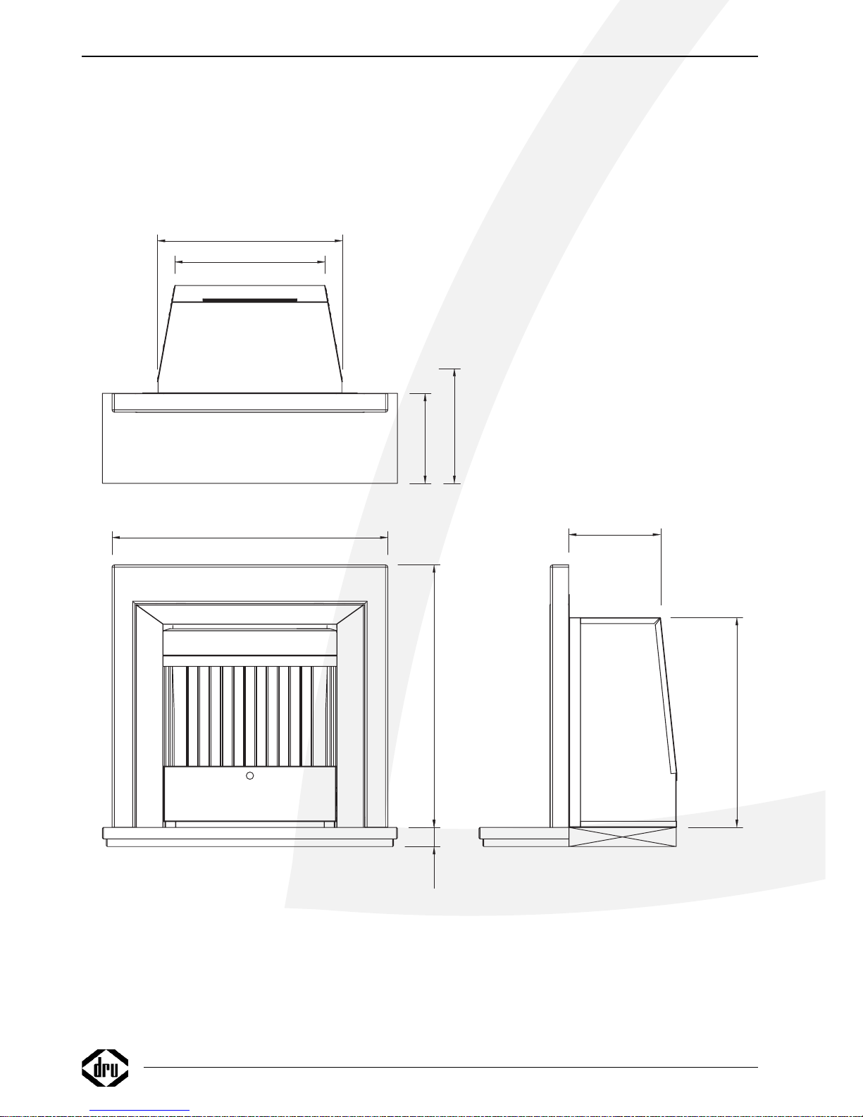
685
548
50
240
483
395
300
235
720
from flame
38c-1012

English
Spirit
1
CONTENTS
CONTENTS
Foreword . . . . . . . . . . . . . . . . . . . . . . . . . . . . . . . . .2
Unpacking . . . . . . . . . . . . . . . . . . . . . . . . . . . . . . . . .2
Connection . . . . . . . . . . . . . . . . . . . . . . . . . . . . . . . .2
Instructions for installation . . . . . . . . . . . . . . . . . . . .2
Type of gas . . . . . . . . . . . . . . . . . . . . . . . . . . . . . . . .2
Important . . . . . . . . . . . . . . . . . . . . . . . . . . . . . . . . .2
Conditions of installation . . . . . . . . . . . . . . . . . . . . .2
Positioning the fire . . . . . . . . . . . . . . . . . . . . . . . . . .2
Fire place opening and chimney catchment space . . .2
Installation the fire . . . . . . . . . . . . . . . . . . . . . . . . . .3
Checking for clearance of combustion products . . . .4
Remote control . . . . . . . . . . . . . . . . . . . . . . . . . . . .4
Connecting the receiver . . . . . . . . . . . . . . . . . . . . . .4
Replacing the batteries in the receiver . . . . . . . . . . .4
Inserting or replacing the batteries
in the remote control . . . . . . . . . . . . . . . . . . . . . . . .4
Operating Instructions . . . . . . . . . . . . . . . . . . . . . . .5
Lighting . . . . . . . . . . . . . . . . . . . . . . . . . . . . . . . . . . .5
Remote Control . . . . . . . . . . . . . . . . . . . . . . . . . . . .5
Pilot light setting . . . . . . . . . . . . . . . . . . . . . . . . . . . .5
Switching off . . . . . . . . . . . . . . . . . . . . . . . . . . . . . . .5
Important . . . . . . . . . . . . . . . . . . . . . . . . . . . . . . . . .5
Flame control . . . . . . . . . . . . . . . . . . . . . . . . . . . . . .5
Installing the fascia . . . . . . . . . . . . . . . . . . . . . . . . . .6
General notes . . . . . . . . . . . . . . . . . . . . . . . . . . . . . .7
Flue-gas protection . . . . . . . . . . . . . . . . . . . . . . . . . .7
Gas safety regulations (for installation & use), 1998 .7
Maintenance and Cleaning . . . . . . . . . . . . . . . . . . . .7
Discoloration of walls an ceiling . . . . . . . . . . . . . . . .7
Lighting the heater for the first time . . . . . . . . . . . . .7
Extra protection . . . . . . . . . . . . . . . . . . . . . . . . . . . .7
Disposal . . . . . . . . . . . . . . . . . . . . . . . . . . . . . . . . . .8
Guarantee . . . . . . . . . . . . . . . . . . . . . . . . . . . . . . . . .8
Installation of the coal . . . . . . . . . . . . . . . . . . . . . . .9
Installation of the twigs . . . . . . . . . . . . . . . . . . . . . .10
Installation of the pebbels/driftwood . . . . . . . . . . . .11
Conversion instruction . . . . . . . . . . . . . . . . . . . . . .14
Technical data . . . . . . . . . . . . . . . . . . . . . . . . . . . . .15
Conditions of warranty
• This appliance has been manufactured and tested by DRU verwarming BV of The Netherlands with utmost care.
• Subject to the conditions set out on this card DRU guarantees the proper operation of this vented room heater to the original purchaser for a period of
one year after date of purchase.
• The guarantee does not cover the normal wear and tear, damage due to incorrect treatment, changes of the equipment or unauthorised installations and
repairs. No liability is assumed by DRU for removal or (re)installation labor costs.
• Under no circumstances shall DRU be liable for incidental,consequential, special or contingent damages or expenses arising directly or indirectly from any
defect in the product or any component or from the use thereof.The remedies set forth herein are the exclusive remedies available to the user and are in
lieu of all other remedies. Subject to specific state laws some of the above limitations or exclusions may not apply to you.
DRU Verwarming B.V.
WARRANTY CARD
Please complete this card and keep it with the invoice to verify purchase date
and to establish the warranty period*.
Model: . . . . . . . . . . . . . . . . . . . . . . . . . . . . . . . . Date: . . . . . . . . . . . . . . . . . . . . . . . . . . . . . . . . . .
Colour: . . . . . . . . . . . . . . . . . . . . . . . . . . . . . . . Serial No.: . . . . . . . . . . . . . . . . . . . . . . . . . . . . . .
Type of Gas: Natural Gas ❑ L.P.G.❑ (please check)
Customer: Dealer/Installer
Name . . . . . . . . . . . . . . . . . . . . . . . . . . . . . . . . . Name . . . . . . . . . . . . . . . . . . . . . . . . . . . . . . . . .
Address . . . . . . . . . . . . . . . . . . . . . . . . . . . . . . . Address . . . . . . . . . . . . . . . . . . . . . . . . . . . . . . . .
City . . . . . . . . . . . . . . . . . . . . . . . . . . . . . . . . . City . . . . . . . . . . . . . . . . . . . . . . . . . . . . . . . . . . .
State . . . . . . . . . . . . . . . . . . . . . . . .ZIP . . . . . State . . . . . . . . . . . . . . . . . . . . . . . . .ZIP . . . . . .
Province . . . . . . . . . . . . . . . . . . . . . .P.C. . . . . . Province . . . . . . . . . . . . . . . . . . . . . .P.C. . . . . . .
Telephone ( . . . . . . . . .) . . . . . . . . . . . . . . . . . .
*FOR SERVICE UNDER THIS WARRANTY CONTACT YOUR DEALER/INSTALLER.
DRU warrants the proper functioning of this vented roomheater if installed by a qualified installer and if used in
strict accordance with the manufacturers operating instructions
Foreword
Dear Customer,
We would like to thank you for buying this DRU product.
Our products have been designed and produced to meet
the highest possible quality, performance and safety
requirements, allowing you to enjoy years of problem-free
use.
In this booklet you will find instructions for the installation
and use of your new log fire. Please read these instructions
and the manual carefully to familiarize yourself with the
appliance. If you require any further support, please do
not hesitate to contact your supplier.
Unpacking
Once the heater has been unpacked, all packaging should
be disposed of in the regular manner.
Connection
This appliance should be connected by a registered
installer.
INSTRUCTIONS FOR INSTALLATION
Type of gas
This appliance is suitable for G20/G31 gasses. Please check
that the local gas and pressure correspond with the
specifications on the type identification tag.This tag can be
found on the inside of the Fire box.All regulations regarding gas installation, including any local regulations, must be
observed at all times. The appliance is to be installed by a
registered installer.
Important
• Keep curtains and any other flammable materials at least
50cm away form the appliance.
• Caution! Touching the heater when hot can cause burns
and blisters!
Conditions of installation
It is the law that all gas appliances are installed only by a
CORGI Registered Installer, in accordance with these
install appliances correctly could lead to prosecution.
Itis in your own interest and that of safety to comply with
the law.
The installation must also be in accordance with all relevant parts of the Local and National Building
Regulations where appropriate, the Building Regulations
( Scotland Consolidation ) issued by the
Scottish Development Department , and all applicable
requirements of the following British
Standard Code of Practice.
• B.S. 6891 Installation of Gas Pipework
• B.S. 5440 Parts 1 & 2 Installation of Flues and Ventilation
• B.S. 1251 Open fire place components
• B.S. 715 Metal flue pipes for gas appliances
• B.S. 6461 Part 1 installation of chimneys and flues
No additional ventilation is required for this appliance.
Positioning the fire
• The gas fire may only be installed in a well-ventilated room
allowing a constant air supply.
• The appliance is suitable for installation in a fireplace or
hearth made of incombustible materials only.
• The chimney must be swept before the appliance is
installed and the flue duct must be tested in accordance
with national guidelines.
• This appliance must only be installed on to a concrete or
non-combustible hearth.
• The hearth material must be a minimum thickness of 13
mm with the top surface at least 50 mm above the floor.
• The hearth must be fitted symmetrically about the fire
opening and have a minimum width of 770mm.The minium
projection of the hearth forwards from the fire opening
must be 235 mm, this is 300 mm in front of the naked
flame (BS 7977-1: 2002).
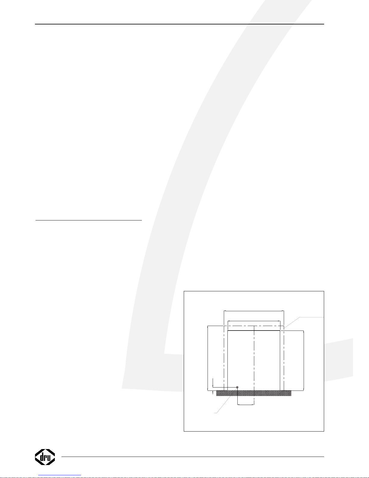
Fire place opening and chimney catchment
space
The front opening of the fire place must be between 490
and 530 wide, and between 560 and 590mm high. If the
opening exceeds these dimensions then a surround must
be constructed from suitable non-combustible material to
produce a suitable sized opening.
Any surrond must be suitably sealed to the fire place to
prevent leakage. (fig 1)
A minimum sized buiders opening with a flat rear face and
no chair brick fitted must be a minimum depth of 300 mm to
accommodate any debris which may fall from the chimney.
2
INSTRUCTIONS FOR INSTALLATION
Minimum flat
sealing area
38c-1013
Min 490
Max 530
560
605
30
155
Min 560
Max 590
Gas supply ø8mm
fig. 1
English
Spirit
INSTRUCTIONS FOR INSTALLATION
3
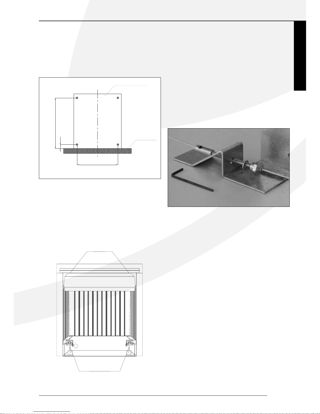
Installation the fire
•
Remove the tray for vermiculite.
•
Remove the burner plate.
•
Mark out and drill 4 holes (8mm) in the back face of the
fire opening in the positions shown in fig 2.
•
Fit the expanding shells with eye bolt and fixing the eyes
securely into the rear of the fire opening.
•
Making the Gas Connection.
•
The gas connection should be made to the appliance inlet
elbow using 8 mm rigid or semirigid tubing.An isolating
elbow or gas cock must be fitted to the pipe work.
•
Uncoil the two fire fixing cables and thread one end of each
of the cables through one of the two holes at the top of
the fire box.
•
Position the fire carefully on the (protected) surface of the
hearth and reach into the fire opening.
Thread each of the cables vertically downwards through the
pair of fixing eyes on the same side of the fire.Thread the
free end of the cables through the corresponding circular
hole on each side of the lower rear of the fire. Carefully
slide the firebox back into the fire opening and pull both
cables tight .
•
Thread a tensioning screw over each of the cables and
ensure that the tensioning nut is screwed fully up against
the hexagon shoulder of the tensioning screw (this provides
maximum travel for the tensioning nut).
•
Fit a screwed nipple on to each of the cables and pull hand
tight up against the tensioning screw, then secure each nipple with a hexagonal wrench.
•
Evenly tighten the tensioning nuts to tension both cables
and pull the fire snugly against the wall.
Do not overtighten, it is only necessary to pull the seal up
against the sealing face of the wall, it does not need to be
compressed. Check that there are no gaps behind the seal.
•
Seal the bottom with lute.
•
With the fire securely in place, if a concealed gas connection has been made through the access hole in the rear of
the fire, the cover should be slid down so that the circular
cutout neatly traps the gas supply pipe.
The securing screws should then be tightened to lock the
cover in positon.
•
Replace the burner plate.
•
Replace the tray for vermiculite.
420
40
Fire opening
Hearth
38c-1014
520
fig. 3
fig. 2
38c-1015
cable holes
cable holes
Checking for clearance of combustion
products
• Close all doors and windows in the room.
• Light the fire and allow to run for approximately
5 minutes on high position.
• After approximately 5 minutes hold a smoke match just
inside and below the centre of the lower front edge of the
top of the fire. (It is recommended that a suiteble smoke
match holder is used when checking for clearance of combustion products ).All smoke generated should be drawn
back into the flue. If slight spillage occurs or if in doubt,
repeat the test after a further 5-10 minutes.
If spillage persists, the flue is not functioning correctly and a
fault exists. If, after investigation the fault cannot be traced
and rectified, the fire must be disconnected from the gas
supply and expert advice obtained.
•
If there is an extrator fan fitted any where in the
vicinity of the appliance, the test should be repeated
with the fan running on maximum and all interconnecting doors open.
•
After ensuring that the fire is safe to use it should be left on
high position to fully warm up.
During this time a slight odour may be noticed, this is due to
the "newness"of the fire and will soon disappear.At this stage
any minor adjustments to the coals should be made using
suitable long handled tongs and taking care not to damage
the coals.
•
Finally, hand the instructions over to the customer and
explain the operation of the fire.
Remote control
Remote control is supplied as a standard accessory.
Batteries, with a life expectancy of approximately one year,
feed the electrical supply.The remote control will only
work if the pilot light is lit.
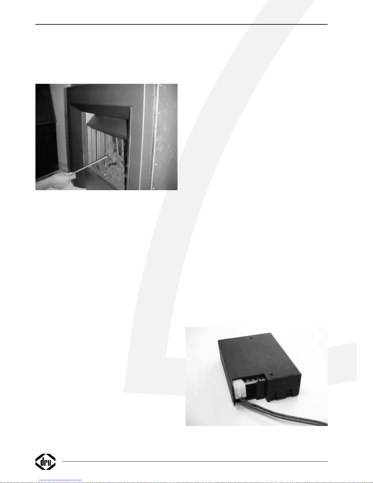
Connecting the receiver
The remote control system comprises a receiver and a
remote control, packed together in one box. The receiver
must be connected to the appliance.
This is done as follows:
• Take the receiver out of the box.
• Slide the plug of the cable onto the receiver circuit board
(fig. 5).
• Connect the wires to the connectors on the gas control
valve.The different sized plugs correspond with the connectors on the gas control valve.
• Open the lid.
• Insert 4 penlight batteries (type AA). Make sure they are
the right way round.
• Replace the lid.
• Place the reciever under the appliance on the floor. Make
sure that the red LED points to the front.
• NB: Fit the receiver as far away from the
burner tray as possible to prevent the receiver from
getting too hot.
Replacing the batteries in the receiver
• Open the flap at the front.
• Take the reciever and open the cover. The batteries are
under that cover.
• Remove the old batteries and insert the new ones, making
sure that the + and – signs on the batteries correspond
with those in the holder.
Inserting or replacing the batteries
in the remote control
• Remove the cover on the back of the remote control.
• Connect a square battery (type 6LR61) to the clip.
• Fit the battery in the holder.
• Replace the cover.
• The temperature is shown on the display in Fahrenheit,
press both buttons for a few seconds and it will change to
Celsius.
NB: Do not throw old batteries in the dustbin.They
should be treated as Chemical Waste.
4
INSTRUCTIONS FOR INSTALLATION
fig. 5
fig. 4
 Loading...