

Dru G20, G25, Solo G20, Solo G25 Instructions For Installation Manual
English
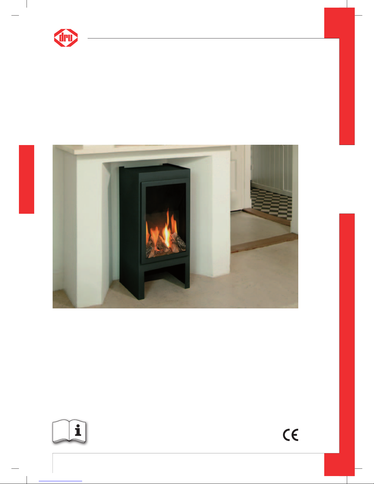
Solo
G20/G25
Please retain this document carefully
Instructions for installation (GB / IE)
UK
95900605 UK Install_G20.indd 195900605 UK Install_G20.indd 1 2-2-10 12:552-2-10 12:55

2
English
SOLO - INSTRUCTION FOR INSTALLATION
Contents
page
Preface 2
1. Introduction 3
2. CE declaration 3
3. SAFETY 3
3.1 General 3
3.2 Regulations 3
3.3 Precautions / safety instructions during installation 3
4. Instructions 4
5. Removing the packaging 4
6. Installation 4
6.1 Regulations 4
6.2 Type of gas 4
6.3 Gas connection 4
6.4 Reconstructing from top connection appliance to back connection appliance 4
6.5 Placing the appliance 5
6.6 Flue gas discharge / combustion air supply system 5
6.7 Connecting gas 10
6.8 Adjusting the appliance 10
6.9 Placing wood set 11
6.10 Pane 11
7. Operation 14
7.1 Wireless remote control 14
8. Final check 15
8.1 Gastightness 15
8.2 Gas pressure / pre-pressure 15
8.3 Ignition pilot and main burner 15
8.4 Flame image 15
9. Maintenance 16
10. Delivery 16
11. Malfunctions 17
Appendix 1 Parts included with the delivery 18
Appendix 2 Technical data 18
Appendix 3 Parts 18
Preface
DRU, a manufacturer of gas heating appliances, develops and produces products that comply with the highest quality, performance and safety requirements.
This guarantees that the user will be able to enjoy using his product for many years to come.
This appliance has a CE marking, which means that it complies with the essential requirements of the European gas
appliance directive.
As an installer, you must be competent in the fi eld of atmospheric gas heating.
Two manuals are supplied with the appliance: the instructions for installation and the operating instructions.
The instructions for installation will provide you with the information you need to install the appliance in such a way
that it will operate properly and safely.
This manual discusses the installation of the appliance and the regulations that apply to the installation. In addition,
you will fi nd technical data for the appliance and information on maintenance, any malfunctions that might occur
and their possible causes.
Please carefully read and use these instructions for installation.
The following symbols are used in the manual to indicate important information:
➠
Work to be performed
!Tip
Suggestions and recommendations
!Caution
You will need these instructions to prevent problems that might occur during installation and/or use.
Caution
You need these instructions to prevent re, personal injury or other serious damages.
After delivery, you should give the operating instructions and the instructions for installation to the user.
UK
95900605 UK Install_G20.indd 295900605 UK Install_G20.indd 2 2-2-10 12:552-2-10 12:55
3
English
SOLO - INSTRUCTION FOR INSTALLATION
1. Introduction
Solo is a freestanding atmospheric gas heating appliance.
This version of Solo is suitable for natural gas.
Solo is a closed appliance. A closed appliance does not extract the combustion air from the living environment, but
from outside. This is done through a combined fl ue gas discharge system / combustion air supply system. In this
concentric system the outer pipe serves as air supply and the inner pipe as fl ue gas discharge.
This system can be installed through the wall, or through the roof.
The concentric system can be supplied in the colour of the appliance.
The appliance is supplied with a battery powered wireless remote control.
2. CE declaration
The undersigned, representative of :
Manufacturer: DRU Haardkachels B.V.
Postbus 37, NL-6660 AA Elst
Industrieweg Oost 11, NL-6662 NE Elst
hereby declares that the design and construction of DRU’ atmospheric gas heating appliance comply with the essential requirements of the Gas Appliance Directive.
Product: atmospheric gas heating appliance
Type: Solo
Applicable EEC directives: 90/396/EEC
Applied harmonized standards: NEN-EN-613
NEN-EN-613/A1
Internal measures by the company guarantee that appliances produced in series comply with the essential requirements of the prevailing EEC directives and the standards derived from them.
This declaration will lose its validity if adjustments are made to the appliance, without prior written permission by
DRU.
On behalf of DRU Haardkachels B.V.
M.J.M Gelten
General director
Postbus 1021, 6920 BA Duiven
Ratio 8, 6921 RW Duiven
3. SAFETY
3.1 General
Caution
- Carefully read this chapter on safety, before you start performing installation or maintenance work;
- Please observe the general regulations and the precautions/safety instructions in this manual.
3.2 Regulations
Please install the appliance in accordance with the applicable national, local and constructional (installation) regulations.
In the Netherlands the “Bouwbesluit” applies, amongst other regulations.
3.3 Precautions / safety instructions during installation
Carefully observe the following precautions/safety regulations:
➠
you should only install and maintain the appliance if you are a competent installer in the eld of atmospheric gas heating;
➠
do not make any changes to the appliance;
➠
only use the ue gas discharge / combustion air supply system supplied by DRU;
➠
place the appliance at a distance of at least 50 mm from the back wall;
➠
do not cover the appliance and the discharge material and/or do not wrap them in an insulation blanket or any other
material;
➠
always place the appliance and/or the discharge pipes at a minimum distance of 500 mm from combustible objects or
materials;
➠
only ever use the supplied wood set;
➠
place the wood set exactly as described;
➠
make sure the pilot burner and the space around it are kept free;
UK
95900605 UK Install_G20.indd 395900605 UK Install_G20.indd 3 2-2-10 12:552-2-10 12:55
4
English
SOLO - INSTRUCTION FOR INSTALLATION
➠
avoid dirt in gas pipes and connections;
➠
check the connections for gastightness before using the appliance;
➠
do not ignite the appliance until it is fully installed;
➠
replace torn or broken panes.
4. Instructions
Observe the following items during installation in order to guarantee a proper and safe operation of the appliance:
➠
avoid that the ignition cable runs over and/or alongside metal parts, in order to prevent weakening of the spark;
➠
avoid damaging the pane during removal/placing;
➠
clean the pane before you use the appliance, in order to prevent dirt from burning in the glass.
5. Removing the packaging
Note the following items when removing the packaging:
➠
Check the appliance for damages during transport.
➠
If necessary, contact your dealer.
After removing the pane, you can take the box containing parts and the wood set from the combustion room.
!Caution
Avoid damaging the pane during removal/placing.
➠
Remove the pane as described in section 6.10.1;
➠
Remove the box containing parts and the wood set from the combustion room.
In Appendix 1 / Table 4 you can see which parts you should have after removing the packaging.
➠
Contact your dealer if you do not have all the parts after you nished removing the packaging;
➠
Dispose packaging in accordance with local regulations.
6. Installation
Read this manual carefully to ensure a proper and safe operation of the appliance.
!Caution
Install the appliance in the order described in this chapter.
6.1 Regulations
- Observe the applicable (installation) regulations.
- Observe the regulations/instructions in this manual.
6.2 Type of gas
The type plate indicates for which type of gas, gas pressure and for which country this appliance is intended. The type
plate can be found at the left side on the back wall of the space at the bottom of the appliance.
➠
Check whether the appliance is suitable for the type of gas and the gas pressure used on site.
!Caution
By default, the appliance is set up for gas type G25. If you connect the appliance to gas type G20, you should change
the primary aeration. For more details, see Table 2 and section 6.8.2
6.3 Gas connection
Place a gas tap in the gas connection, close to the appliance.
Caution
Avoid dirt in the gas pipe and in the connections.
The following requirements apply to the gas connection:
- use a gas pipe with the correct dimensions, so that no pressure loss can occur:
- the gas tap should have the CE marking;
- you should always be able to reach the gas tap.
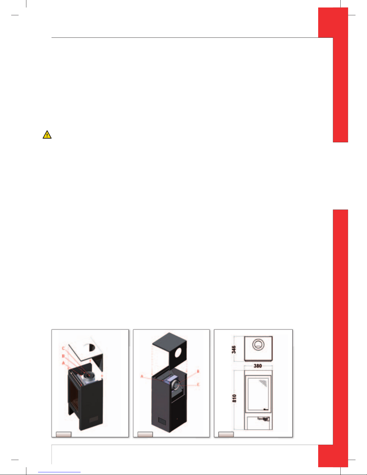
6.4 Reconstructing from top connection appliance to back connection appliance
By default, the appliance is supplied with a top connection (see Fig. 1) for the fl ue gas discharge./ combustion air
supply system. The top connection can be reconstructed to a back connection (see
Fig. 2).
The back connection is required if the appliance is directly connected to a wall duct. In all other cases, the top connection will be used.
UK
95900605 UK Install_G20.indd 495900605 UK Install_G20.indd 4 2-2-10 12:552-2-10 12:55
5
English
SOLO - INSTRUCTION FOR INSTALLATION
Proceed as follows, when reconstructing to a back connection:
➠
Take aluminium bend C from the air inlet stub; see Fig. 1;
➠
Unscrew the 8 parkers A from the air inlet stub; see Fig. 1;
➠
Turn air inlet stub B 90 degrees, as indicated in Fig. 2;
➠
Fix the air inlet stub again by using the 8 parkers;
➠
Place back the aluminium bend, as indicated.
!Caution
The upper plate will only be placed when the appliance is on its intended location, as described below in section 6.5.
6.5 Placing the appliance
Place the appliance as follows:
Caution
- Always place the appliance at a minimum distance of 500 mm from combustible objects and/or materials.
- Do not make any changes to the appliance;
- Place the appliance at a distance of at least 50 mm from the back wall;
- Do not cover the appliance and the discharge material and/or do not wrap it in an insulation blanket or any other
material.
➠
Determine the location of the appliance; the dimensions can be found in Fig. 3.
➠
Provide a gas connection at the location. For details, see section 6.3.
➠
Make a duct for the ue gas discharge/combustion air supply system with the following diameters. For details, see
section 6.6.
- Ø160 mm for a wall duct through incombustible material;
- Ø 250 mm for a wall duct through combustible material;
- Ø160 mm for a roof duct through incombustible material;
- Ø 250 mm for a roof duct through combustible material.
➠
Place the appliance on its intended location.
The top plate of the appliance is supplied separately. The opening should be attached to the back by using the back
connection. When using the top connection, the opening will be placed on the top.
!Tip
Avoid damaging the top plate by immediately placing it in the required position.
➠
Place the top plate (see Fig. 1 and 2).
6.6 Flue gas discharge / combustion air supply system
6.6.1 General
The appliance is of the C11/C31 type.
The appliance is connected to a combined fl ue gas discharge/combustion air supply system, hereafter referred to
as the concentric system.
The passage to the outside can be made with a wall duct (see section 6.6.2) or with a roof duct (see section 6.6.3).
If necessary, you can also use an existing discharge channel (see section 6.6.4).
Fig. 1 Fig. 2 Fig. 3
UK
95900605 UK Install_G20.indd 595900605 UK Install_G20.indd 5 2-2-10 12:552-2-10 12:55
6
English
SOLO - INSTRUCTION FOR INSTALLATION
Caution
- Only use the concentric system supplied by DRU (Ø100 / Ø150 mm). This system was tested in combination with the
appliance.
DRU cannot guarantee a good and safe operation of other systems and cannot accept liability for them;
- For connecting to an existing chimney ue you should only use the installation set supplied by DRU;
- Always place the concentric system at a minimum distance of 500 mm from combustible objects and/or materials;
- Maintain a distance of at least 50 mm between the concentric system and combustible objects and/or materials.
The concentric system is constructed from (the discharge stump of) the appliance.
If structural circumstances require that the concentric system is placed fi rst, the appliance can later be connected
with a telescopic pipe piece.
!Tip
DRU does not recommend placing the telescopic piece, because this visible pipe piece cannot be supplied in colour
and does not really combine well with the appliance.
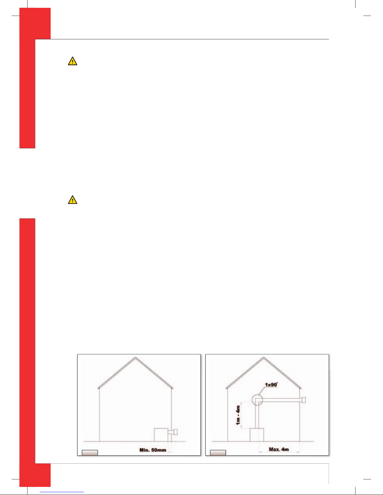
6.6.2 Application with wall duct
There are 2 methods of connecting the appliance to the wall duct:
1. directly onto the wall duct; see
Fig. 4a. In this situation the appliance should be reconstructed to a back connection
(see section 6.4);
2. indirectly onto the wall duct; see
Fig. 4b. Under these circumstances, the top connection of the appliance is
used.
When placing the wall duct, you must take the following aspects into account:
Caution
- Use heat-resistant isolation material when passing through combustible material;
- The rosette (mounting inner plate) of the wall duct is too small to seal the Ø 250 mm opening when passing through
combustible material. That is why you should rst apply a su ciently large heat-resistant intermediate plate to the
wall. Then, the rosette is mounted on the intermediate plate.
!Caution
Some heat-resistant isolation materials contain volatile components that will spread an unpleasant smell for a pro-
longed time; these are not suitable.
Below you will fi nd the conditions for constructing and placing in more detail.
6.6.2.1 Direct connection to the wall duct
If the appliance is directly connected to the duct wall (see Fig. 4a), it will be necessary to change the primary aeration
of the burner. Table 2 contains the conditions for adjusting, and section 6.8, Adjusting the appliance, describes how
the primary aeration can be adjusted. The baffl e will not be placed.
Proceed as follows, when placing the wall duct:
!Caution
The top plate of the appliance is placed with the opening to the back.
➠
Determine the length of the duct;
➠
Make sure the wall duct has the right dimensions.
!Caution
- Make sure that the right insertion length is maintained;
- Place the wall duct with the groove/folded seam at the top;
➠
Mount the rosette (mounting inner plate); if necessary, on a heat resistant intermediate plate when passing through
combustible material;
➠
Attach the wall duct from the outside with four screws in their respective holes.
Fig. 4bFig. 4a
UK
95900605 UK Install_G20.indd 695900605 UK Install_G20.indd 6 2-2-10 12:562-2-10 12:56
 Loading...