

Page 1

INSTALLATIEVOORSCHRIFT EN GEBRUIKERSHANDLEIDING NL/BE
CONSIGNES D’INSTALLATION ET NOTICE D’UTILISATION FR/BE/LU/CH
INSTALLATION INSTRUCTIONS AND USER MANUAL GB/IE
INSTALLATIONSVORSCHRIFT UND GEBRAUCHSANWEISUNG DE/AT/BE/LU/CH
INSTRUÇÕES DE INSTALAÇÃO E MANUAL DO UTILIZADOR PT
SABA SL
Bewaar dit document zorgvuldig
Lees de handleiding in zijn geheel zorgvuldig door
Conservez soigneusement ce document
lisez attentivement la notice dans son intégralité
Conserve este documento com cuidado
Please keep this document carefully
Read the whole manual thoroughly
Heben Sie dieses Dokument bitte sorgfältig auf.
Lesen Sie die Gebrauchsanweisung bitte sorgfältig und vollständig durch
Leia com atenção o manual na íntegra
957.605.01
DRU VER W ARMING B.V.
HOLLAND
Page 2
2
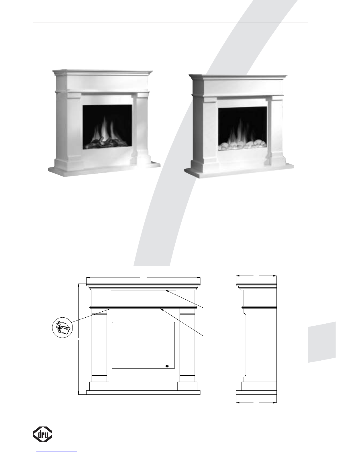
Foto 1 Foto 2
376
376
1055
1027
Lucht uitlaat
Lucht inlaat
1
0
38c-1192
Page 3
Nederlands
1
Saba SL
LEES DIT EERST VOORD
AT U HET APPARAAT INSTALLEERT OF GAAT GEBRUIKEN
HET ZICH NIET HOUDEN AAN ONDERSTAANDE AANWIJZINGEN KAN SCHADE OF ERNSTIG
LICHAMELIJK LETSEL VEROORZAKEN
Belangrijke veiligheidsaanwijzigingen
• Voor alle onderhoud en service werkzaamheden moet de stekker uit de contactdoos genomen worden
• Raadpleeg als de schouw of het toestel beschadigd is direct de leverancier voordat het toestel met de schouw wordt
geïnstalleerd en voordat het apparaat in bedrijf wordt genomen.
• Gebruik de haard en de schouw niet buiten.
• Plaats de haard en de schouw niet in een vochtige omgeving of nabij een bad douche of zwembad.
• De uitlaat van de warme lucht en de inlaat voor de koude lucht mogen op geen enkele wijze geheel of gedeeltelijk
worden geblokkeerd zie figuur A.
• Het is niet toegestaan het toestel en/of de schouw te voorzien van een isolatie deken of op enige wijze in te pakken.
• Het toestel en de verwarminingsset (verwarmingselement, ventilator, schakelaar en kabelboom) welke is ingebouwd in de
schouw is geschikt voor 230V, 50Hz en heeft een aansluitwaarde van maximaal 1400 Watt.
• De stekker moet na installatie altijd bereikbaar zijn.
• De wandcontactdoos waarop de toestel/schouw combinatie wordt aangesloten dient geaard te zijn.
• Plaats de schouw met het toestel niet onder de wandcontactdoos aangezien deze door warmte aangetast zou kunnen
worden, houd hier tevens rekening mee met de hete lucht uitlaat zie figuur A.
• Leg het netsnoer nooit in de buurt van de hete lucht uitlaat.
• Zorg ervoor dat evt. overgordijnen of andere brandbare materialen minstens 1 meter van het toestel/schouw combinatie
verwijderd zijn.
• Het verdient aanbeveling het toestel/schouw combinatie door een erkende installateur te laten installeren volgens
geldende voorschriften.
• Laat geen kinderen of hulpbehoevende personen in de buurt van de haard zonder toezicht en houd de afstandsbediening
buiten bereik van kinderen en hulpbehoevenden.
• Gebruik deze toestel/schouw combinatie niet in combinatie met andere regelapparatuur zoals een timer, thermische
regelaar of een geprogrammeerde controller wat er voor zorgt dat de toestel/schouw combinatie automatisch inschakelt
(de toestel/schouw combinatie zou bedekt kunnen zijn of iemand zou de toestel/schouw combinatie ongemerkt
verplaatst kunnen hebben) het geen zou kunnen leiden tot brand.
• In geval van storing de stekker uit de wandcontactdoos nemen.
• Natte kleding, handdoeken e.d. niet op de kachel te drogen hangen!
• Door het toestel/schouw combinatie met de afstandsbediening op stand by te zetten blijft er een kleine stroom door het
toestel lopen, het verdient de aanbeveling voor het uitschakelen de aan uit schakelaar te gebruiken.
• Het toestel/schouw combinatie NIET gebruiken bij omgevingstemperaturen lager dan 2ºC en hoger als 40ºC.
• Het toestel/schouw combinatie NIET gebruiken als de luchtvochtigheid meer dan 80% bedraagt.
• Het toestel/schouw combinatie NIET gebruiken boven de 2000 mtr.
• Let op: Het toestel weegt ongeveer 30 kg, het is raadzaam het toestel niet zonder hulp te verplaatsen.
• Let op: De schouw weegt ongeveer 52kg, het is raadzaam de schouw niet zonder hulp te verplaatsen
Page 4
2
WAARSCHUWINGEN
Let op!
Bijzondere gegevens, respectievelijk geboden en verboden ten aanzien van schade preventie
Let op!
Lees de handleiding
Let op!
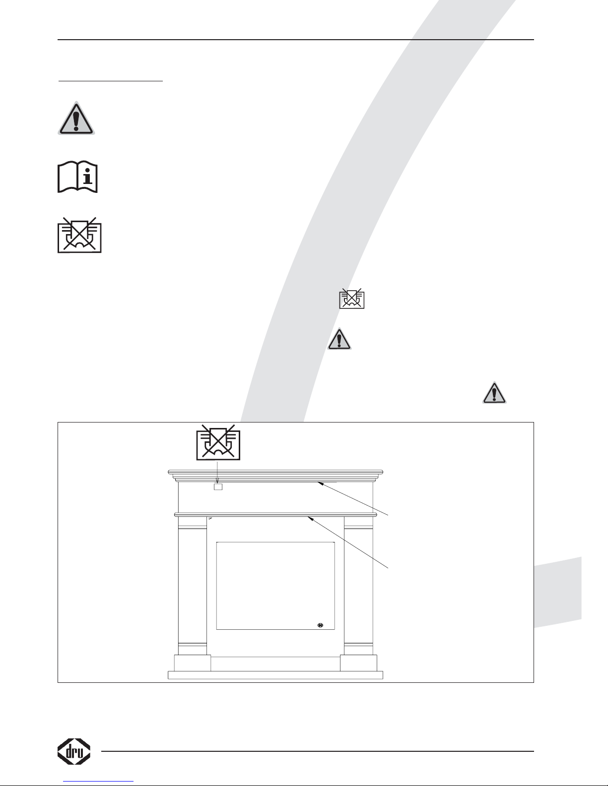
Zorg er voor dat in- en uitlaten van lucht niet geblokkeerd worden
1. Het symbool op de voorzijde van de schouw bij de hete lucht uitlaat en figuur A geeft aan dat de schouw
op deze plek bijzonder heet is en dat door het afdekken van deze uitlaat het toestel en/of de schouw oververhit kunnen
raken.
2. Let op! Aanraking van hete delen kan brandwonden veroorzaken!
3. In geval van beschadiging van 1 van beide glasplaten van het toestel mag het toestel niet meer gebruikt worden.
4. Neem altijd de stekker uit de wandcontactdoos alvorens werkzaamheden aan het toestel/schouw combinatie te
verrichten, eventueel kunt u de groep waarom u toestel/schouw combinatie is aangesloten uitschakelen.
Controleer of het toestel/schouw combinatie spanningsloos is alvorens aan de werkzaamheden te beginnen.
Lucht uitlaat
Lucht inlaat
38c-1196
Figuur A
Page 5

Nederlands
3
Saba SL
CE-VERKLARING
Hierbij verklaren wij, dat de hierna te noemen elektrische sfeerhaard/schouw door haar ontwerp en bouwwijze en in de
door ons in het verkeer gebrachte uitvoering aan de in de desbetreffende, in EG-Richtlijnen vervatte, fundamenteleveiligheids- en gezondheidseisen voldoet.
Ingeval van zonder overleg met ons aangebrachte veranderingen aan het toestel en/of de schouw verliest deze verklaring
haar geldigheid.
Product: Elektrische sfeerhaard/schouw combinatie
Type: Saba SL
Van toepassing zijnde EG-richtlijnen
73/23/EEC
89/336/EEC
Toegepaste geharmoniseerde normen:
IEC 60335-1
IEC 60335-2-30
EN 55014-1
EN 55014-2
EN 61000-3-2
EN 61000-3-3
Door bedrijfsinterne maatregelen is gewaarborgd dat seriematig geproduceerde apparatuur altijd aan de eisen van de van
kracht zijnde EG-richtlijnen en de toegepaste normen voldoet.
Handtekening
R. Gelten
Dru verwarming B.V.
Postbus 1021, 6920 BA Duiven
Ratio 8, 6921 RW Duiven
www.dru.nl
Page 6

4
Page 7
5
Saba SL
Nederlands
INHOUD
Veiligheidsaanwijzingen . . . . . . . . . . . . . . . . . . . . . . . .1
Waarschuwingen . . . . . . . . . . . . . . . . . . . . . . . . . . . . .2
Conformiteitsverklaring . . . . . . . . . . . . . . . . . . . . . . . .3
Garantiebepalingen . . . . . . . . . . . . . . . . . . . . . . . . . . .5
Woord vooraf . . . . . . . . . . . . . . . . . . . . . . . . . . . . . . .6
Inleiding . . . . . . . . . . . . . . . . . . . . . . . . . . . . . . . . . . . .6
Verpakking . . . . . . . . . . . . . . . . . . . . . . . . . . . . . . . . . .6
Uitpakken . . . . . . . . . . . . . . . . . . . . . . . . . . . . . . . . . . .6
Ontvangst . . . . . . . . . . . . . . . . . . . . . . . . . . . . . . . . . . .6
Installatie . . . . . . . . . . . . . . . . . . . . . . . . . . . . . . . . . . .6
Aansluiten . . . . . . . . . . . . . . . . . . . . . . . . . . . . . . . . . .6
Vastzetten van de haard in de schouw . . . . . . . . . . . .7
Plaatsen van toestel/schouw combinatie,
vrije ruimte om het toestel . . . . . . . . . . . . . . . . . . . . .7
Draadloze bediening . . . . . . . . . . . . . . . . . . . . . . . . . .8
Plaatsen of vervangen van de batterijen in de
afstandsbediening . . . . . . . . . . . . . . . . . . . . . . . . . . . . .8
In- en uitschakelen van het
toestel/schouw combinatie . . . . . . . . . . . . . . . . . . . . .8
Verwijderen voorste ruit . . . . . . . . . . . . . . . . . . . . . . .9
Eerste maal gebruik maken van de verwarming . . . . .9
Plaatsen kiezels . . . . . . . . . . . . . . . . . . . . . . . . . . . . .10
Algemene opmerkingen . . . . . . . . . . . . . . . . . . . . . . .11
Onderhoud en reiniging . . . . . . . . . . . . . . . . . . . . . .11
Extra bescherming . . . . . . . . . . . . . . . . . . . . . . . . . . .11
Thermische beveiliging . . . . . . . . . . . . . . . . . . . . . . . .12
Afdanken/ milieubescherming . . . . . . . . . . . . . . . . . . . .
Registratiekaart . . . . . . . . . . . . . . . . . . . . . . . . . . . . .12
Storingen . . . . . . . . . . . . . . . . . . . . . . . . . . . . . . . . . .13
Technische gegevens . . . . . . . . . . . . . . . . . . . . . . . . .13
INHOUD
GARANTIEBEWIJS
Wilt u dit garantiebewijs volledig invullen en samen met de rekening bij uw toestel bewaren.
Invullen in blokletters s.v.p.
Type: . . . . . . . . . . . . . . . . . . . . . . . . . . . . . . . . . . . Aankoopdatum: . . . . . . . . . . . . . . . . . . . . . . . . . . .
Kleur: . . . . . . . . . . . . . . . . . . . . . . . . . . . . . . . . . . Serienummer (op typeplaat): . . . . . . . . . . . . . . . . .
Koper: Leverancier:
Naam . . . . . . . . . . . . . . . . . . . . . . . . . . . . . . . . . . . Naam . . . . . . . . . . . . . . . . . . . . . . . . . . . . . . . . . . .
Adres . . . . . . . . . . . . . . . . . . . . . . . . . . . . . . . . . . . Adres . . . . . . . . . . . . . . . . . . . . . . . . . . . . . . . . . . .
Postcode . . . . . . . . . . . . . . . . . . . . . . . . . . . . . . . . Postcode . . . . . . . . . . . . . . . . . . . . . . . . . . . . . . . . .
Plaats . . . . . . . . . . . . . . . . . . . . . . . . . . . . . . . . . . . Plaats . . . . . . . . . . . . . . . . . . . . . . . . . . . . . . . . . . . .
IN GEVAL VAN STORINGEN, DIENT U ZICH ALTIJD TOT UW LEVERANCIER TE WENDEN.
DRU Verwarming garandeert de goede werking van dit apparaat bij vakkundige installatie
en gebruik volgens de gebruiksaanwijzingen.
Garantiebepalingen
• DRU Verwarming B.V. garandeert de goede werking van het toestel/schouw combinatie en staat er voor in dat het toestel/schouw combinatie met de
grootste zorg is vervaardigd van deugdelijk materiaal.
• De garantie geldt gedurende 1 jaar na datum van aankoop.
• Onder de garantie vallen alle gebreken, die een gevolg zijn van fouten in de constructie of voor de constructie gebruikte onderdelen.
• DRU Verwarming verplicht zich gedurende de garantieperiode gratis vervangende onderdelen te leveren.Het 1ste jaar van de garantietermijn zullen - dit
ter beoordeling van DRU Verwarming B.V. - geen kosten in rekening worden gebracht.
• De garantie vervalt als storingen het gevolg zijn van foutieve installatie, van verkeerd gebruik of onjuist onderhoud. De garantie vervalt tevens indien
onderdelen vervangen worden door andere dan de originele onderdelen en indien plaatsing en/of reparaties door onbevoegden wordt uitgevoerd.
• Indien het opsturen van het apparaat naar de fabriek noodzakelijk is dient dit franco te gebeuren.Het garantiebewijs en een kopie van het aankoopbewijs
s.v.p.meesturen.
• Wanneer u aanspraak wilt maken op fabrieksgarantie, wilt u dan eerst contact opnemen met uw leverancier
• Wilt u bij uw garantiebewijs ook de rekening van uw leverancier bewaren. Bij serviceverlening zal men hier naar vragen.
DRU Verwarming B.V.
Page 8
6
Woord vooraf
Geachte klant,
Vriendelijk bedankt voor de aankoop van dit DRU
product. Onze producten zijn ontwikkeld en gefabriceerd
volgens de hoogst mogelijke kwaliteit-, prestatie- en
veiligheidseisen. Hierdoor kunt u rekenen op jarenlang
probleemloos gebruiksplezier.
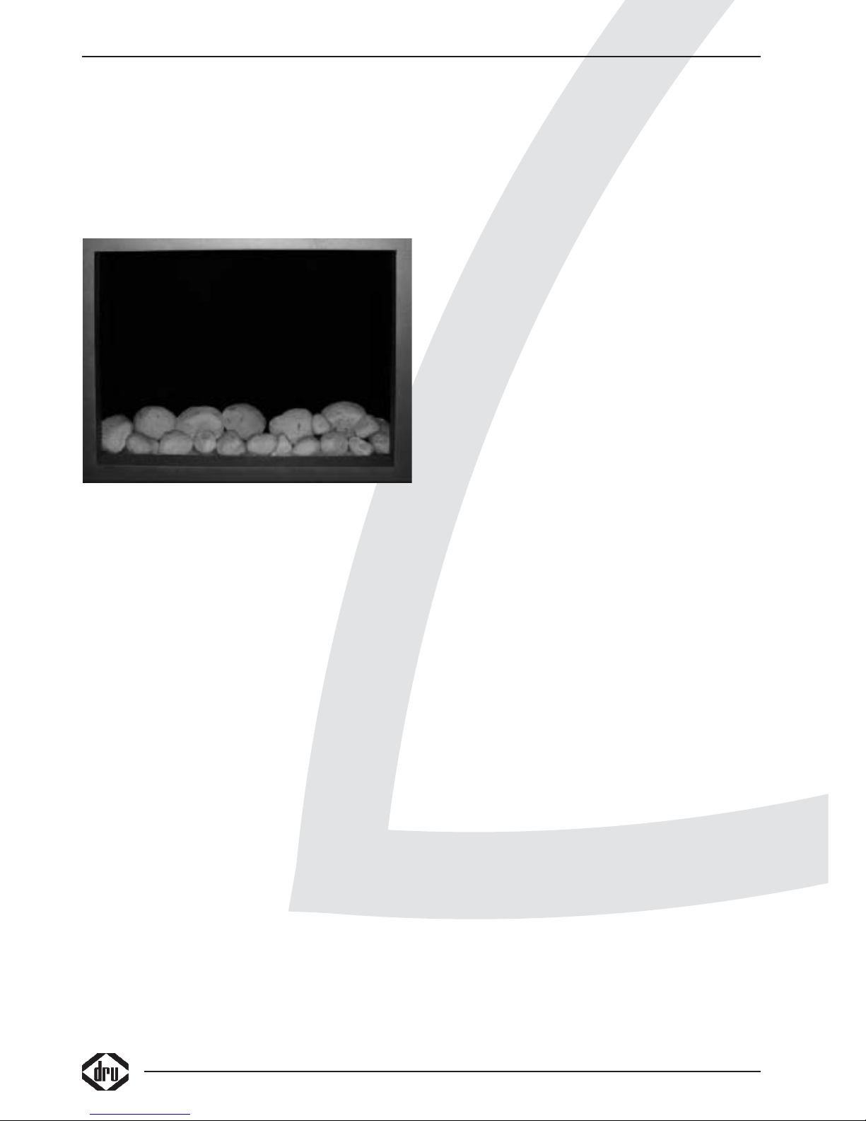
De toestel/schouw combinatie is te verkrijgen in twee
uitvoeringen, de hout uitvoering (zie foto 1) en de kiezel
(zie foto 2) uitvoering (zie het plaatsen van de
kiezels).
Het vlameffect van deze sfeerhaard kan gebruikt worden
met en zonder verwarming.
De verwarming welke in de schouw is geplaatst kan in
twee standen worden gebruikt namelijk 650 Watt of 1300
Watt.
Ieder moment van de dag kunt u genieten van een
rustgevend realistisch vlameffect wat gegenereerd wordt
door de modernste technologie. Het energie-verbruik
benodigd voor het vlamverbruik is bijzonder laag
(ongeveer 12 Watt)
Dit DRU toestel is ontworpen als set in combinatie
met de bijbehorende schouw. Het toestel kan niet
los gebruikt worden aangezien de schakelaar van
het toestel extern in de schouw geplaatst word,
tevens is het verwarmingselement in de schouw
geplaatst.
De schouw is voorzien van luchtinlaat aan de voorzijde
onder in het bovenste deel en een hete lucht uitlaat aan
de voorzijde boven (zie figuur A).
In dit boekje vindt u instructies voor installatie en gebruik
van uw nieuwe toestel/schouw combinatie.
Lees de instructies en gebruikershandleiding goed door,
zodat u zich vertrouwt maakt met het toestel/schouw
combinatie.
Wilt u meer ondersteuning, neem dan contact op met uw
leverancier.
Deze toestel/schouw combinatie voldoet aan de geldende
CE richtlijnen
Inleiding
In deze handleiding vindt u informatie over de inbouw van
het toestel in de bijbehorende schouw, het onderhoud,
milieu aspecten, en de veiligheidsvoorschriften.
Neem de handleiding zorgvuldig door voor u de
toestel/schouw combinatie plaatst en bewaar deze goed
op een veilige plaats.
Verpakking
De schouw en het toestel mogen alleen getransporteerd
worden in de daarvoor bedoelde verpakking. Door geen
gebruik te maken van de juiste verpakking kan er
transportschade ontstaan waardoor weer gevaarlijke
situaties kunnen ontstaan.
Uitpakken
Wanneer u klaar bent met uitpakken, dient de verpakking
via de reguliere weg te worden afgevoerd.
Bewaar de verpakking tot de toestel/schouw combinatie
geïnstalleerd is en de goede werking is getest.
Ontvangst
Bij ontvangst moet gecontroleerd worden of de verpakking
onbeschadigd is, is dit niet het geval dient u contact op te
nemen met uw leverancier.
Gebruik het artikel bij beschadigde verpakking in geen
geval,
Installatie
Laat de toestel/schouw combinatie door een erkende
vakhandelaar plaatsen in overeenstemming met de
daarvoor geldende voorschriften.
Aansluiten
Het toestel (en hiermee tevens de verwarmingsset in de
schouw) dient te worden aangesloten op een geaarde
wandcontactdoos.
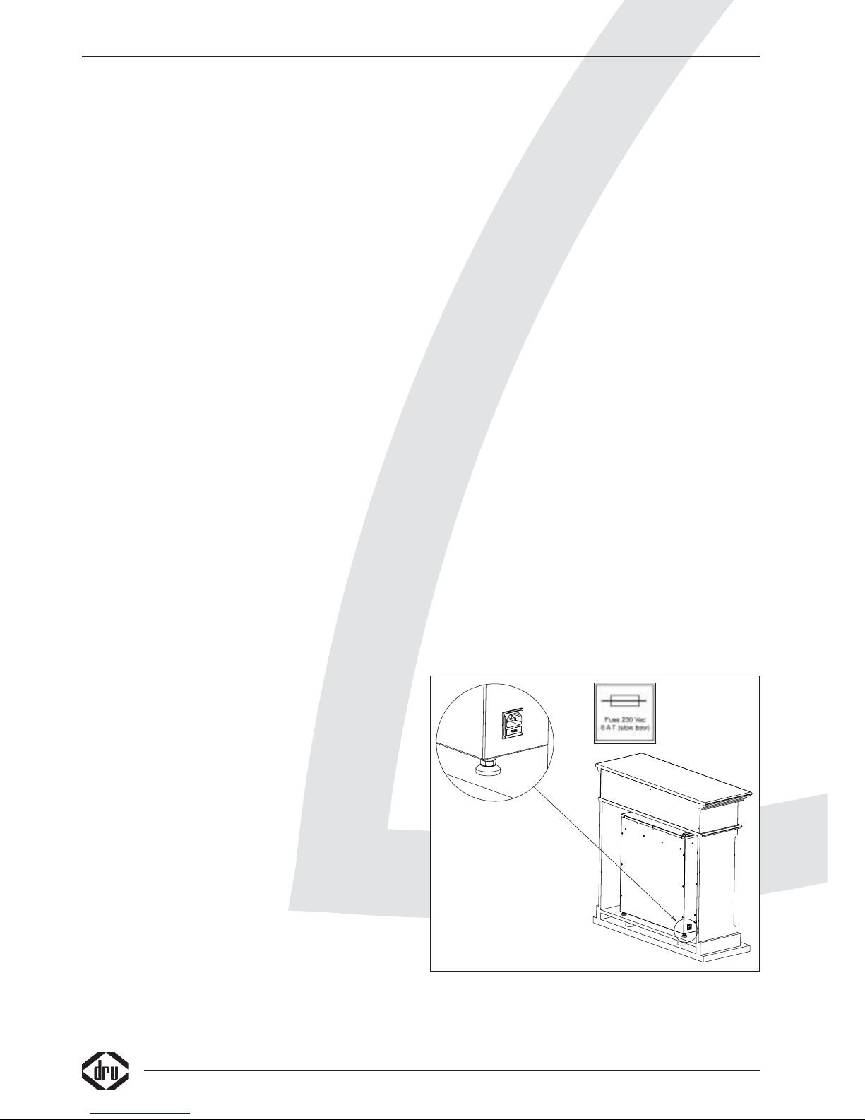
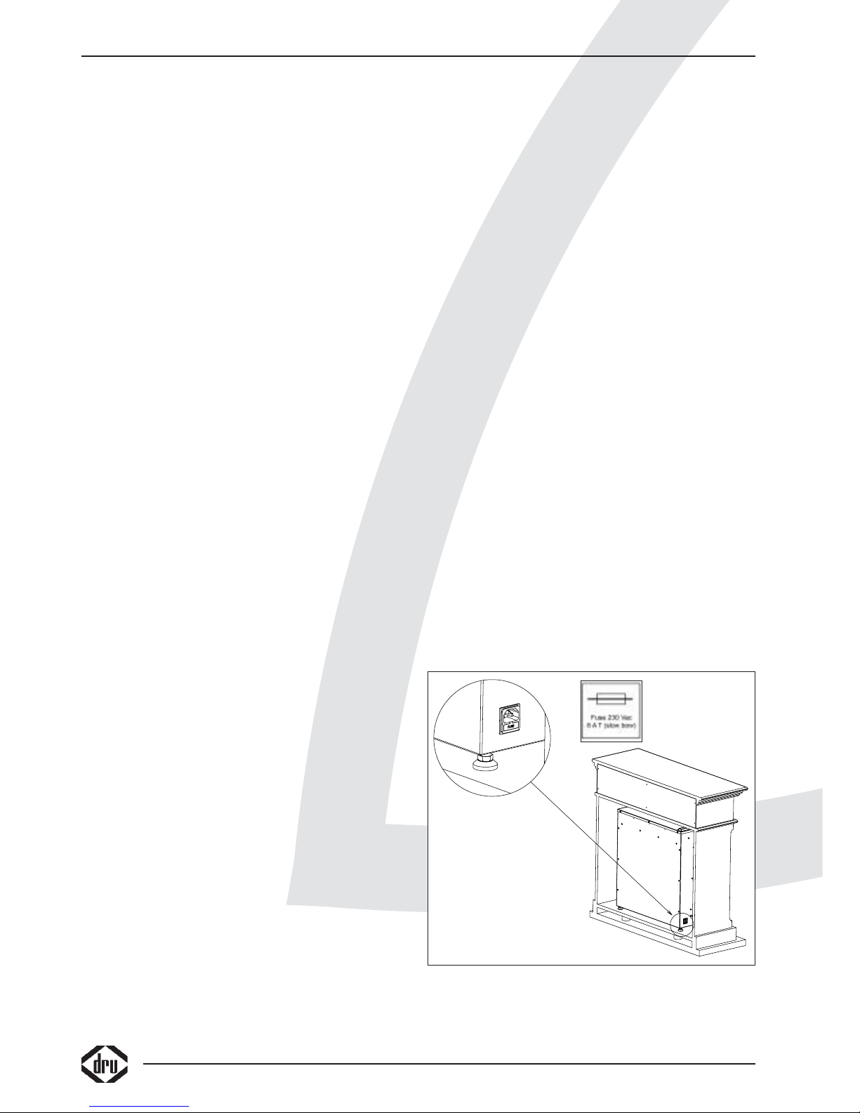
Het opgenomen vermogen (met beide
verwarmingselementen aan) door het toestel is ruim 1300
Watt. Der halve is de sfeerhaard voorzien van 2 stuks 8
Ampere trage zekeringen welke in de netentree zijn
geplaatst (zie figuur C)
INSTALLATIEVOORSCHRIFT
38c-1195
Figuur C
Page 9
7
Saba SL
Nederlands
Het is zaak rekening te houden met andere
toestellen/apparaten die op dezelfde groep zijn
aangesloten zodat het maximale stroomverbruik
van deze groep niet overschreden wordt.
U kunt het toestel/schouw combinatie aansluiten door
het bijgeleverde netsnoer in de netentree te plaatsen,
nadat de verwarmingsset door de 8-polig kabel op het
toestel is aangesloten zie ook Plaatsen van toestel,
vrije ruimte om het toestel
Vastzetten van de haard in de schouw
De haard staat op 4 stelpoten, zodra deze juist gesteld
zijn staat de haard redelijk stabiel.
Om er voor te zorgen dat de haard niet verschuift tijdens
schoonmaken moet de haard aan beide kanten met de
beugels (reeds voorgemonteerd in de schouw) vastgezet
worden (zie figuur D)
Plaatsen van toestel, vrije ruimte om het toestel
Het toestel is ontworpen om in te bouwen in de
bijbehorende schouw. De ruimte achter en om het
toestel wordt geregeld door de schouw.
De inbouwhoogte van het toestel in de schouw is
afhankelijk van de instelling van de stelvoeten, verdraai de
stelvoeten zodanig dat vanaf de voorzijde alleen het glas
van het toestel zichtbaar is.
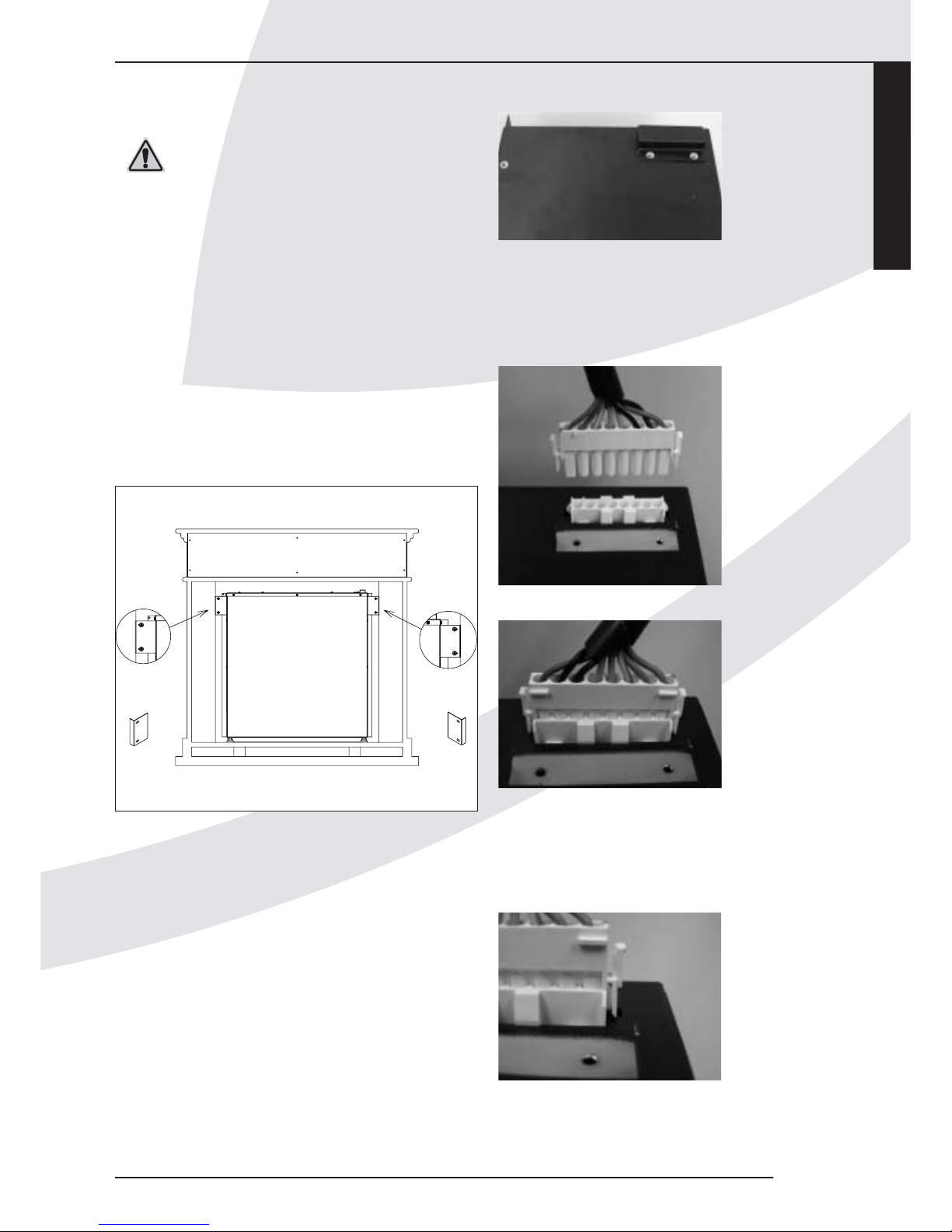
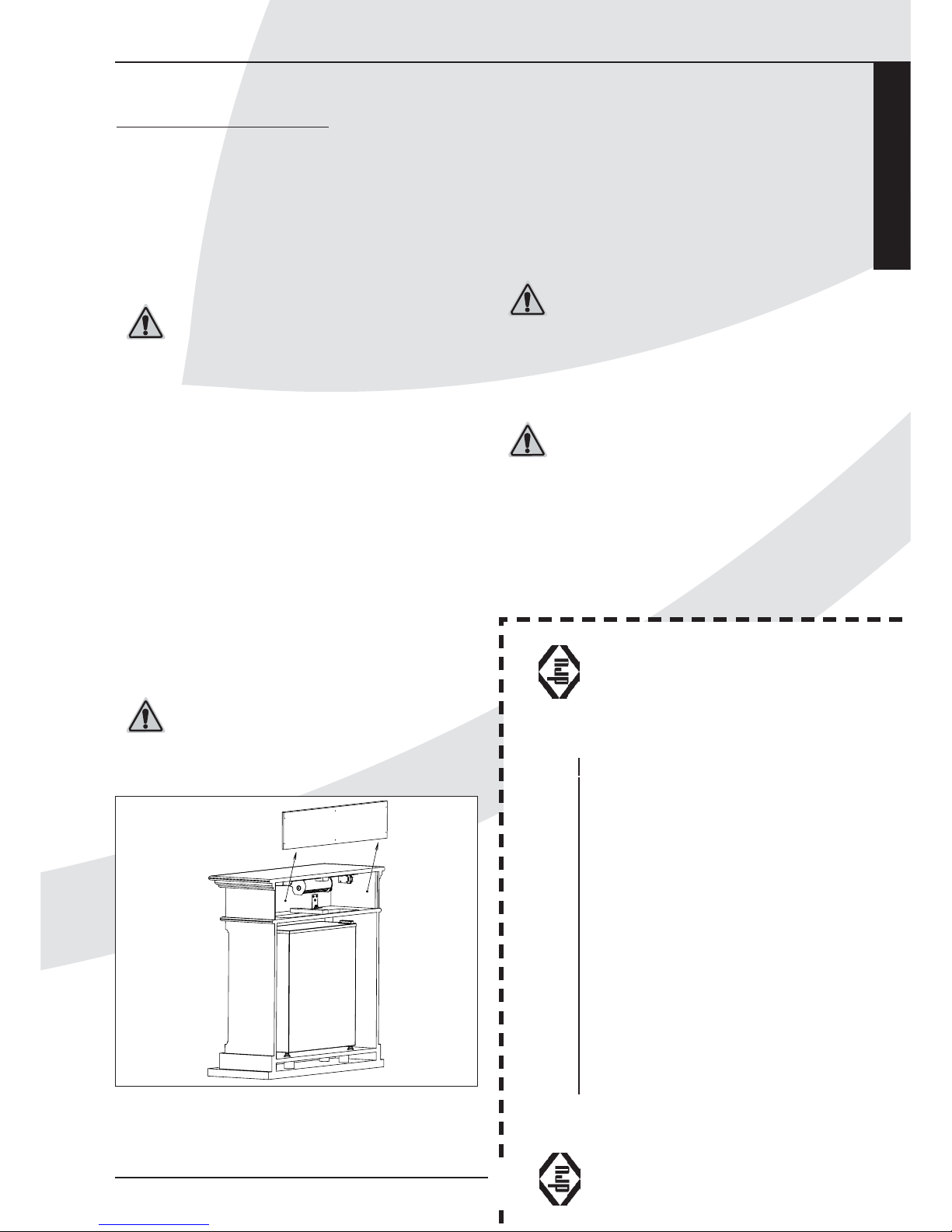
Demonteer het beschermkapje van de deksel van het
toestel (zie figuur E)
Plaats vervolgens het toestel van achteraf in de schouw
(zie figuur C) en zet deze vast met de beugels (zie
figuur D).
Sluit de brede 8-polige stekker die uit de schouw komt
aan op de eveneens 8-polige contra stekker op de deksel
van het toestel (Figuur F en G)( hiermee verbind u de
schakelaar en de verwarmingset in de schouw met het
toestel).
U kunt de 8-polige stekker (foto) maar op een manier
plaatsen, druk de stekker stevig aan tot de vergrendelingen aan de zijkanten vastklikken (zie figuur H)
INSTALLATIEVOORSCHRIFT
38c-1193
Figuur D
Figuur E
Figuur F
Figuur G
Figuur H
Page 10
8
INSTALLATIEVOORSCHRIFT
Als voorgaande is aangesloten kunt u nu uw toestel
aansluiten op de geaarde wandcontactdoos met de
bijgeleverde kabel.
Als alles werkt kunt u uw toestel/schouw combinatie
tegen de wand schuiven.
Draadloze bediening
De toestel/schouw combinatie wordt standaard geleverd
met een draadloze bediening. Hiermee kunnen de in de
schouw geplaatste verwarmingselementen aan en uit gezet
worden, kan de lichtintensiteit (hoogte van het vlameffect)
aangepast worden en kan het toestel op stand by gezet
worden.
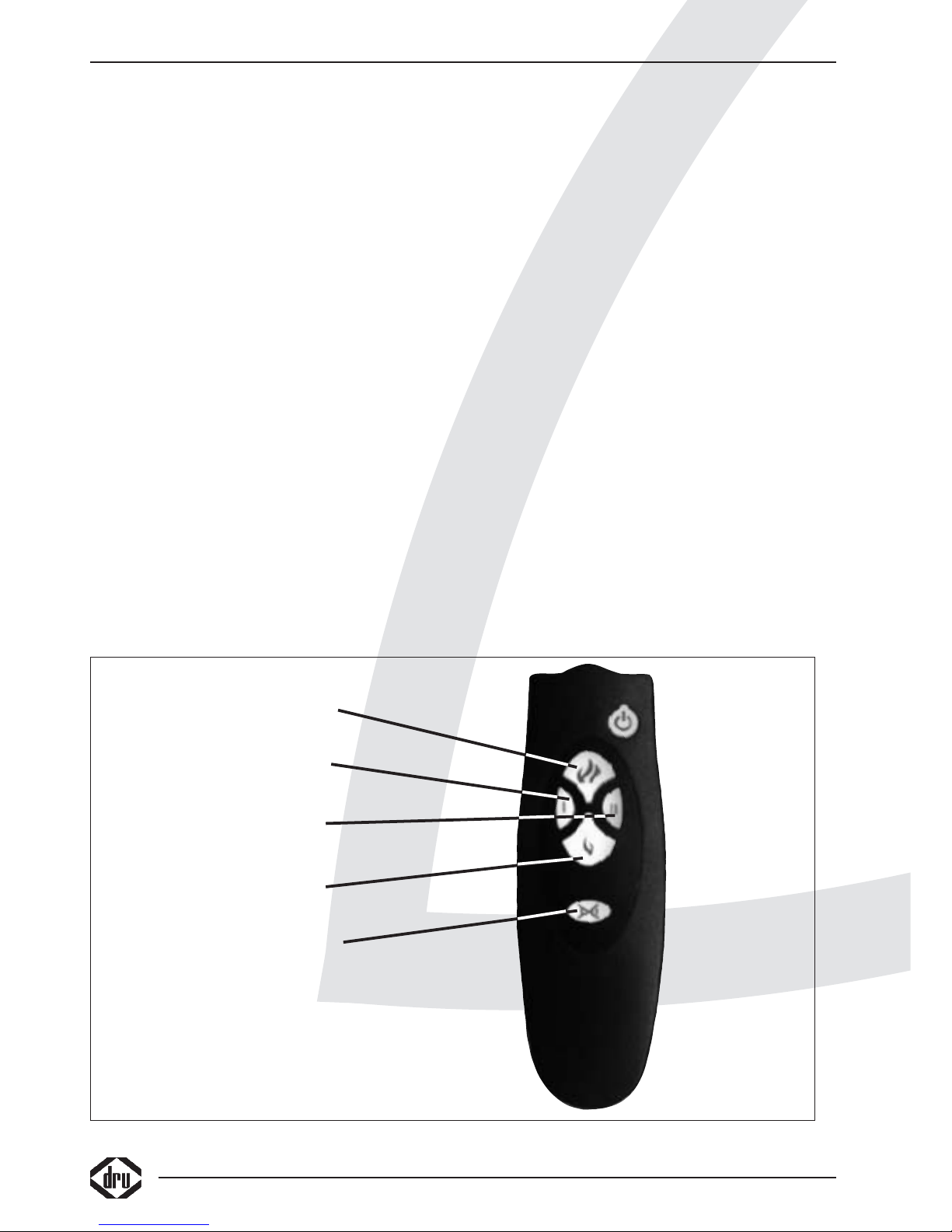
Hieronder zijn de symbolen op de afstandsbediening
verklaard zie figuur
De hoogte van het vlameffect kan ingesteld worden door
één of meerdere malen op de kleine of grote vlam te
drukken. Het dimmen gaat in stapjes dus de knop
meerdere malen indrukken om te dimmen.
Door 1 in te drukken gaat verwarmingselement I aan (650
Watt), drukt u I nogmaals in gaat element 1 weer uit,
hetzelfde geld voor II.
Als u eerst I en dan II in drukt gaan beide
verwarmingselementen aan (1300 Watt), door
achtereenvolgens I en II weer in te drukken (u kunt een
lichte klik horen) zullen de elementen weer uit zijn.
Door op de knop I II met het kruis er door in te
drukken schakelt u beide elementen uit ongeacht of
I of II of beide zijn ingedrukt.
De elektrische voeding van de afstandsbediening wordt
verzorgd door batterijen. De levensduur van de batterijen
is ongeveer één jaar.U moet tijdens de bediening van de
afstandsbediening deze richten op het toestel omdat het
gaat om een infrarood afstandsbediening.
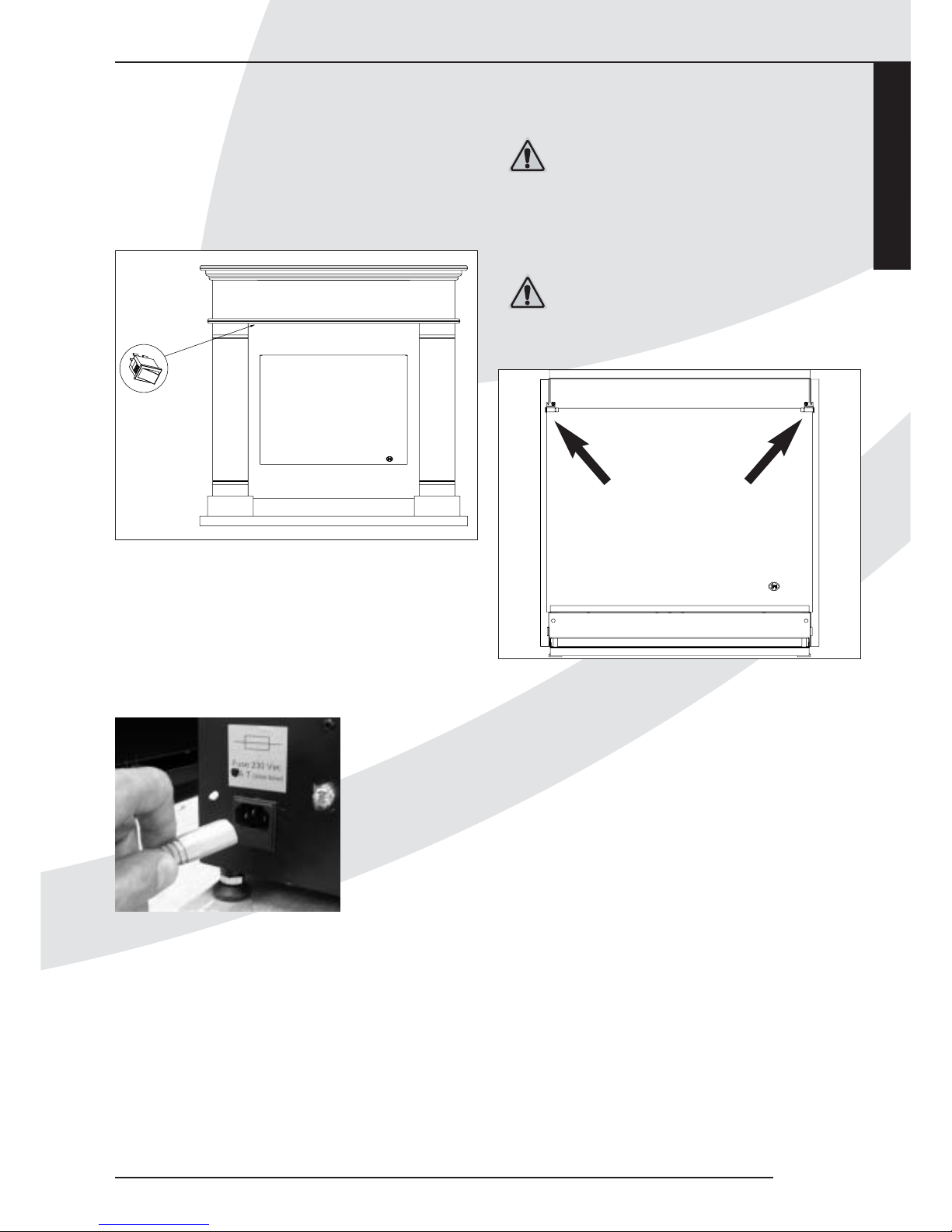
De afstandsbediening werkt alleen wanneer de
hoofdschakelaar links boven in de schouw (zie figuur I)
op 1 is gezet (dit kunt u eventueel zien door er onder te
kijken).
Plaatsen of vervangen van de batterijen in de
afstandsbediening
• Verwijder de deksel aan de onderzijde van de
afstandsbediening.
• Plaats de twee batterijen van het type AAA in de houder
en let hierbij op de plus en min aanduiding.
Let op: gebruik van batterijen die niet lekvrij zijn kan de
afstandbediening onherstelbaar beschadigen.
• Sluit de deksel.
Let op: oude batterijen mogen niet bij het huisvuil maar
moeten bij het Klein Chemisch Afval.
gebruikershandleiding
In- en Uitschakelen van het toestel/schouw
combinatie.
Door de schakelaar aan de linkerbovenkant van de schouw
te bedienen (0 of 1) kan de toestel/schouw combinatie uit
of aangezet worden.
Vlammen en gloeieffect
Hoger (in stapjes drukken)
Verwarmingselement I
Aan of uit
Verwarmingselement II
Aan of uit
Vlammen en gloeieffect
Lager (in stapjes drukken)
Verwarmingselementen I en II uit
Page 11
Saba SL
Let op: door de toestel/schouw combinatie hier uit te
zetten verbruikt de toestel/schouw combinatie geen
stroom meer, het verdient altijd de aanbeveling wanneer
de toestel/schouw combinatie voor langere tijd (de nacht
bijvoorbeeld) uitgezet wordt dit met deze schakelaar te
doen.
Verwijderen voorste ruit
Neem de stekker uit de contactdoos
Schuif de schouw met het toestel er in naar voren.
Neem de 230 Volt stekker uit het toestel. (Zie figuur K)
Neem de 8 polige stekker boven op het toestel los door
de lipjes van de stekker aan de bovenzijde in te drukken
en de stekker naar boven toe los te nemen. (Zie figuur F
en Figuur G)
Demonteer de 2 beugels waar het toestel mee vast in de
schouw geplaatst door de 4 schroeven (2 aan beide zijden)
los te nemen. (zie figuur D)
Om de voorste ruit te verwijderen dient u de lipjes
op de bovenste hoeken van de ruit te demonteren,
let er op dat de glasruit gemakkelijk kan breken en
dat daardoor lichamelijk letsel kan ontstaan.
Wees dus voorzichtig bij het los nemen of bel uw
leverancier.
(zie figuur J).
Dit kunt u doen door de parkers los te draaien.
Monteren gaat in de omgekeerde volgorde.
LET OP: de achterste ruit mag niet losgenomen
worden.
Eerste maal gebruik maken van de verwarming
Tijdens het eerste gebruik van de verwarmingselementen
kan er een onaangename geur ontstaan, dit wordt
veroorzaakt door het aanwezige stof en het gebruik van
het element materiaal voor de eerste keer.
Ventileer goed, de geur verdwijnt snel na een aantal keren
opwarmen.
Blijft er een onaangename geur ontstaan neem dan contact
op met uw leverancier.
Nederlands
INSTALLATIEVOORSCHRIFT
9
1
0
38c-1197
Figuur I
Figuur K
38c-1200
Figuur J
Page 12
Plaatsen kiezels voordat het toestel in de
schouw geplaatst wordt
Voor het plaatsen van de kiezels dient u de voorste ruit te
verwijderen (zie verwijderen voorste ruit).
Plaats de kiezels volgens figuur L, de grote kiezels horen
tegen de donkere ruit geplaatst te worden.
Monteer de ruit weer voorzichtig.
INSTALLATIEVOORSCHRIFT
10
Figuur L
Page 13
ALGEMENE OPMERKINGEN
Onderhoud en reiniging
Bij onderhoud moet er worden zorggedragen dat de
elektronica niet beschadigd door statische elektriciteit.
Zorg er voor dat indien het toestel verplaatst wordt
allereerst de stekker uit de contactdoos is verwijderd en
dat altijd de stekker bovenop het toestel losgenomen
wordt (figuur F en G)
Zorg altijd dat de stekker uit de wandcontactdoos
of uit het toestel is genomen of de groep waarop
het toestel/schouw combinatie is aangesloten is
uitgeschakeld.
Uw toestel/schouw combinatie dient jaarlijks te worden
gecontroleerd, het verdient de aanbeveling dit door een
gekwalificeerd bedrijf te laten doen.
Zorg dat het toestel/schouw combinatie is afgekoeld en
dat de set spanningsvrij is voor dat met reinigen of
inspectie wordt begonnen.
De controle en het onderhoud dienen in ieder geval een
goede en veilige werking van de toestel/schouw
combinatie te garanderen. Schakel hiervoor uw installateur
of een gespecialiseerd onderhoudsbedrijf in.
Het verdient aanbeveling om het toestel regelmatig op
stofvorming te controleren en zonodig stofvrij te maken of
te laten maken.
Om de luchtinlaat en de warme lucht uitlaat op
stofvorming te kunnen controleren moet het achterpaneel
van de schouw losgenomen worden (zie figuur N)
Let er op dat de toestel/schouw combinatie
spanningsvrij is door de steker uit het toestel te
nemen alvorens het achterpaneel los te nemen (zie
figuur N)
Zonodig kan de ventilator met de stofzuiger en een zachte
kwast worden gereinigd, zorg er voor dat de ventilator
egaal word gereinigd zodat er geen onbalans ontstaat. Raak
de ventilator niet aan met harde delen, hierdoor kan
onbalans ontstaan.
Op de binnenkant van het voorste glasraam kan zich na
verloop van tijd stof ophopen U kunt het verwijderen met
een glasreiniger of een vochtige doek zie verwijderen
voorste ruit
Bij het reinigen van de mantel en schouw geen
bijtende of schurende middelen gebruiken.
Lakbeschadigingen, bijvoorbeeld door het plaatsen
van voorwerpen op of tegen de mantel en/of de
schouw, vallen buiten de garantie.
Extra bescherming
Indien het toestel/schouw combinatie in een
vertrek geïnstalleerd wordt waar jonge kinderen of
hulpbehoevende mensen zonder toezicht verblijven,
adviseren wij het toestel/schouw combinatie af te
schermen en de afstandsbediening op een veilige
plek op te bergen.
Nederlands
ALGEMENE OPMERKINGEN
38c-1194
Figuur N
REGISTRATIEKAART
DRU Verwarming kan alleen garantie verlenen indien deze registratiekaart volledig en duidelijk
in blokletters en binnen 5 dagen opgestuurd is aan DRU Verwarming B.V.
Type: . . . . . . . . . . . . . . . . . . . . . . . . . . . . . . . . . . . . . . Aankoopdatum: . . . . . . . . . . . . . . . . . . . . . . . . . . . . . . . . .
Kleur: . . . . . . . . . . . . . . . . . . . . . . . . . . . . . . . . . . . . . Serienummer (op typeplaat): . . . . . . . . . . . . . . . . . . . . . .
Koper . . . . . . . . . . . . . . . . . . . . . . . . . . . . . . . . . . . . . Detaillist/installateur: . . . . . . . . . . . . . . . . . . . . . . . . . . . . .
Naam . . . . . . . . . . . . . . . . . . . . . . . . . . . . . . . . . . . . . Naam . . . . . . . . . . . . . . . . . . . . . . . . . . . . . . . . . . . . . . . . .
Adres . . . . . . . . . . . . . . . . . . . . . . . . . . . . . . . . . . . . . Adres . . . . . . . . . . . . . . . . . . . . . . . . . . . . . . . . . . . . . . . . .
Postcode . . . . . . . . . . . . . . . . . . . . . . . . . . . . . . . . . . . Postcode . . . . . . . . . . . . . . . . . . . . . . . . . . . . . . . . . . . . . .
Plaats . . . . . . . . . . . . . . . . . . . . . . . . . . . . . . . . . . . . . . Plaats . . . . . . . . . . . . . . . . . . . . . . . . . . . . . . . . . . . . . . . . .
Telefoon . . . . . . . . . . . . . . . . . . . . . . . . . . . . . . . . . . . Telefoon . . . . . . . . . . . . . . . . . . . . . . . . . . . . . . . . . . . . . . .
Hartelijk dank voor uw medewerking.
✂
Page 14
Thermische beveiliging
In de verwarmingsset welke geplaatst is in de schouw is
een thermische beveiliging opgenomen om oververhitting
te voorkomen, deze kan optreden als de uitlaat voor
warme lucht wordt belemmerd (zie figuur A)
Na afkoeling zal het verwarmingselement weer
inschakelen.
Mocht deze beveiliging om wat voor een reden dan ook
zomaar inschakelen, dan dient u contact op te nemen met
uw leverancier.
Afdanken
De verpakkingsmaterialen zijn recyclebaar,
gooi deze dus niet bij het huisvuil weg maar
zorg er voor dat ze gerecycled kunnen
worden.
Indien u het toestel vervangt of verwijdert, moet u het
toestel via de reguliere weg afvoeren.Voordat tot
demontage wordt overgegaan eerst het toestel vrij van de
netspanning maken door de het netsnoer los te koppelen
of de groep waarop het toestel is aangesloten spanningsvrij
te maken.
Oude apparaten bevatten waardevolle
materialen die gerecycled kunnen worden,
geef oude apparaten daarom bij een geschikte
verzamelplaats af.
Garantie
Gelieve de REGISTRATIEKAART binnen 5 dagen na
aankoop in te vullen en op te sturen in een envelop
zonder postzegel naar het onderstaande adres.
DRU VERWARMING B.V.
ANTWOORDNUMMER 4551
6920 ZX DUIVEN
Het GARANTIEBEWIJS (blz. 1) kunt u zelf behouden.
De garantie gaat in op het ogenblik, dat de volledig
ingevulde registratiekaart door DRU Verwarming is
ontvangen.
V
OOR BELGIË DE KAAR
T INVULLEN OP PAGINA 9.
BEWAAR DEZE HANDLEIDING ZORGVULDIG.
✂
VERSTUREN IN EEN
ENVELOP
DRU VERWARMING B.V.
ANTWOORDNUMMER 4551
6920 ZX DUIVEN
ALGEMENE OPMERKINGEN
Page 15

13
STORINGEN
Het is zeer onwaarschijnlijk dat er zich storingen
voordoen, in het geval er zich toch een storing voordoet
adviseren wij u uw leverancier te raadplegen.
Mogelijke storingen:
Het toestel heeft wel een vlameffect en de
ventilator in de schouw doet het ook alleen er
komt geen warmte lucht meer uit de schouw.
Mogelijk heeft de thermische beveilig ingegrepen, na
verloop van tijd zal de beveilig afkoelen en er weer
warmte gegenereerd worden.
Mocht de beveilig direct weer ingrijpen en het
verwarmingselement uitschakelen, dan dient u uw
leverancier te raadplegen.
Het toestel doet niets meer.
Neem de stekker uit het toestel, en controleer of de beide
zekeringen in de netentree niet defect zijn.
Als de zekeringen defect zijn kunt u nieuwe plaatsen (2
stuks van 8 Ampere Traag) en de stekker weer
terugplaatsen, als de zekeringen opnieuw defect raken
moet u contact opnemen met uw
leverancier. Plaats onder geen enkele
voorwaarde zekeringen van meer als 8
Ampere dit zou bij kortsluiting ernstige
gevolgen kunnen hebben.
De haard reageert niet meer op de
afstandbediening:
Mogelijk zijn de batterijen van uw afstandbediening leeg,
plaats nieuwe en indien het probleem zich nog voordoet
kunt u uw leverancier raadplegen.
TECHNISCHE GEGEVENS
Elektrische aansluiting
Nominale spanning (50 Hz) 230-240 Volt ac
Opgenomen vermogen zonder verwarming ongeveer 12
Watt
Opgenomen vermogen met 1 verwarmingselement in
bedrijf ongeveer 650 Watt
Opgenomen vermogen met beide verwarmingselementen
in bedrijf ongeveer 1300 Watt
Toestelzekeringen (netentree) 2 stuks 8 Ampere Traag
Beschermklasse I
Afmetingen Schouw
Breedte 1055 mm
Hoogte 1027 mm
Diepte 376 mm
Materiaal Schouw: MDF
Afmetingen Toestel
Breedte 623 mm
Hoogte (afhankelijk van stelpoten) minimaal 658mm
Diepte 225 mm
Nederlands
STORINGEN TECHNISCHE GEGEVENS
Page 16

14
Photo 1 Photo 2
376
376
1055
1027
Lucht uitlaat
Lucht inlaat
1
0
38c-1192
laisser u d’air
entree u d’air
Page 17

Français
15
Saba SL
VEUILLEZ LIRE CE QUI SUIT AVANT DE PROCÉDER À L’INSTALLATION OU À LA MISE EN
MARCHE DE L’APPAREIL. LE NON-RESPECT DES INSTRUCTIONS CONSIGNÉES CI-DESSOUS
PEUT ENTRAÎNER DES DOMMAGES CORPORELS OU D’AUTRES DOMMAGES SÉRIEUX.
Importantes consignes de sécurité
• Débranchez la fiche de la prise de courant avant de procéder à toutes activités d’entretien et de réparation.
• En cas de dommage, contactez directement votre fournisseur avant de faire installer l’ensemble foyer
électrique/cheminée décorative ou de mettre l’appareil en marche.
• N’installez pas le foyer et la cheminée décorative à l’extérieur.
• Ne placez pas le foyer et la cheminée dans un environnement humide ou près d’un bac à douche ou d’une piscine.
• La sortie d’air chaud ou l’arrivée d’air froid ne doivent en aucun cas être obstruées, partiellement ou totalement. Voir
figure A
• Il est formellement interdit d’envelopper l’appareil et/ou la cheminée d’une couche d’isolant ou d’une quelconque façon.
• L’appareil et l’ensemble des éléments de chauffage (unité de chauffage, ventilateur, interrupteur et le faisceau électrique)
qui sont intégrés dans la cheminée sont conçus pour 230 V, 50 Hz et ont une puissance de maximale de 1400 Watt.
• L’interrupteur doit rester accessible après l’installation du foyer.
• La prise de courant murale à laquelle sont raccordés l’ensemble foyer/cheminée doit toujours avoir une broche terre.
• Ne placez pas l’ensemble foyer/cheminée en dessous de la prise de courant murale car celle-ci pourrait être
endommagée par la chaleur. Faites aussi attention à la sortie d’air chaud, voir figure A.
• Ne placez jamais le câble d’alimentation à proximité de la sortie d’air chaud.
• Veillez à ne placer aucun matériel inflammable, des double-rideaux par exemple, à moins de 1 m de l’ensemble
foyer/cheminée.
• Il est conseillé de faire installer l’ensemble foyer/cheminée par un installateur agréé qui suivra les consignes en vigueur.
• Ne laissez pas les enfants ou les personnes dépendantes sans surveillance à proximité du foyer et placez la
télécommande hors de leur portée.
• N’utilisez pas l’ensemble foyer/cheminée avec d’autres appareils de réglage, comme un minuteur, un régulateur
thermique ou un système d’allumage automatique du foyer (un objet peut avoir été déposé sur le foyer ou quelqu’un
peut avoir déplacé le foyer sans qu’on s’en rende compte) ; cela pourrait causer un incendie.
• En cas de panne, retirez la fiche de la prise murale.
• Aucun vêtement mouillé, serviette ou autre, ne doit être mis à sécher sur le foyer/cheminée !
• Lorsque l’ensemble foyer/cheminée est mis en veilleuse au moyen de la télécommande, il continue d’être alimenté par un
courant minimal ; il est donc conseillé de l’éteindre au moyen de l’interrupteur.
• N’utilisez PAS le foyer/cheminée lorsque la température ambiante est inférieure à 2ºC ou supérieure à 40ºC.
• N’utilisez PAS le foyer/cheminée lorsque le taux d’humidité de l’air est supérieur à 80%.
• N’utilisez PAS le foyer/cheminée à une altitude supérieure à 2000 mètres.
• Attention : Le foyer pèse environ 30 kg. Il est donc conseillé d’être à plusieurs pour le déplacer.
• Attention : La cheminée pèse environ 52 kg. Il est donc conseillé d’être à plusieurs pour la déplacer.
Page 18

16
AVERTISSEMENTS
Attention !
Informations très importantes concernant ce qu’il faut faire/ne pas faire pour prévenir des dommages
Attention !
Veuillez lire attentivement cette notice
Attention !
Veillez à ce que ni l’arrivée ni la sortie d’air ne soient obturées
1. Le symbole placé sur la façade de la cheminée près de la sortie d’air chaud et sur la figure A indiquent que la
cheminée irradie énormément de chaleur à cet endroit et qu’en obturant cette bouche d’évacuation, l’appareil et/ou la
cheminée risquent de surchauffer.
2.Attention ! Risques de brûlure si l’on touche les parties dégageant de la chaleur !
3. En cas d’endommagement d’une des deux vitres de l’appareil, il faut immédiatement cesser d’utiliser l’appareil.
4.Veillez à toujours retirer la fiche de la prise murale avant d’effectuer des travaux sur l’appareil et déconnectez
éventuellement le groupe auquel l’ensemble foyer/cheminée est raccordé.Vérifiez que l’ensemble n’est plus sous
tension avant de commencer les travaux.
Figure A
Lucht uitlaat
Lucht inlaat
38c-1196
laisser u d’air
entree u d’air
Page 19
Français
17
Saba SL
DÉCLARATION DE CONFORMITÉ CE
Par la présente, nous déclarons que l’ensemble foyer électrique/cheminée décorative, dans sa conception et son mode de
fabrication et dans la version que nous mettons en vente, satisfait aux exigences fondamentales en matière de sécurité et
de protection de la santé telles qu’elles sont formulées dans les directives européennes concernées.
En l’absence de consultation de DRU Verwarming B.V. au sujet d’une modification apportée à l’appareil et/ou à la cheminée
décorative, cette déclaration n’est plus valable.
Produit : ensemble foyer électrique/cheminée décorative
Type : Saba SL
Directives CE s’appliquant :
73/23/EEC
89/336/EEC
Normes harmonisées en application
IEC 60335-1
IEC 60335-2-30
EN 55014-1
EN 55014-2
EN 61000-3-2
EN 61000-3-3
Les règles internes de l’entreprise garantissent la conformité des appareils produits en série aux exigences des directives
CE en vigueur et des normes en application.
Signature
R. Gelten
Dru verwarming B.V.
Postbus 1021, 6920 BA Duiven
Ratio 8, 6921 RW Duiven
www.dru.nl
Page 20

18
Page 21
Saba SL
Français
SOMMAIRE
19
SOMMAIRE
Consignes de sécurité . . . . . . . . . . . . . . . . . . . . . . . .15
Avertissements . . . . . . . . . . . . . . . . . . . . . . . . . . . . .16
Déclaration de conformité . . . . . . . . . . . . . . . . . . . .17
Dispositions de garantie . . . . . . . . . . . . . . . . . . . . . .19
Avant-propos . . . . . . . . . . . . . . . . . . . . . . . . . . . . . . .20
Introduction . . . . . . . . . . . . . . . . . . . . . . . . . . . . . . . .20
Emballage . . . . . . . . . . . . . . . . . . . . . . . . . . . . . . . . . .20
Déballage . . . . . . . . . . . . . . . . . . . . . . . . . . . . . . . . . .20
Réception . . . . . . . . . . . . . . . . . . . . . . . . . . . . . . . . . .20
Installation . . . . . . . . . . . . . . . . . . . . . . . . . . . . . . . . .20
Raccordement . . . . . . . . . . . . . . . . . . . . . . . . . . . . . .20
Fixation du foyer à la cheminée décorative . . . . . . .21
Installation de l’ensemble foyer/cheminée
décorative, espace autour de l’appareil . . . . . . . . . . .21
Télécommande sans fil . . . . . . . . . . . . . . . . . . . . . . .22
Introduction ou remplacement des piles dans la
télécommande . . . . . . . . . . . . . . . . . . . . . . . . . . . . . .22
Allumage/extinction de l’appareil/cheminée . . . . . . .23
Retrait de la vitre avant . . . . . . . . . . . . . . . . . . . . . . .23
Première mise en marche du chauffage . . . . . . . . . .23
Pose des cailloux . . . . . . . . . . . . . . . . . . . . . . . . . . . .24
Remarques générales . . . . . . . . . . . . . . . . . . . . . . . . .25
Entretien et nettoyage . . . . . . . . . . . . . . . . . . . . . . . .25
Mesures de protection supplémentaires . . . . . . . . . .25
Sécurité thermique . . . . . . . . . . . . . . . . . . . . . . . . . .26
Mise au rebut/protection de l’environnement . . . . .26
Carte d’enregistrement . . . . . . . . . . . . . . . . . . . . . . .26
Pannes . . . . . . . . . . . . . . . . . . . . . . . . . . . . . . . . . . . .27
Données techniques . . . . . . . . . . . . . . . . . . . . . . . . .27
Garantiebepalingen
DRU Verwarming B.V. garandeert de goede werking van het toestel/schouw combinatie en staat er voor in dat het toestel/schouw combinatie met de
grootste zorg is vervaardigd van deugdelijk materiaal.
• De garantie geldt gedurende 1 jaar na datum van aankoop.
• Onder de garantie vallen alle gebreken, die een gevolg zijn van fouten in de constructie of voor de constructie gebruikte onderdelen.
• DRU Verwarming verplicht zich gedurende de garantieperiode gratis vervangende onderdelen te leveren.Het 1ste jaar van de garantietermijn zullen - dit
ter beoordeling van DRU Verwarming B.V. - geen kosten in rekening worden gebracht.
• De garantie vervalt als storingen het gevolg zijn van foutieve installatie, van verkeerd gebruik of onjuist onderhoud. De garantie vervalt tevens indien
onderdelen vervangen worden door andere dan de originele onderdelen en indien plaatsing en/of reparaties door onbevoegden wordt uitgevoerd.
• Indien het opsturen van het apparaat naar de fabriek noodzakelijk is dient dit franco te gebeuren.Het garantiebewijs en een kopie van het aankoopbewijs
s.v.p.meesturen.
• Wanneer u aanspraak wilt maken op fabrieksgarantie, wilt u dan eerst contact opnemen met uw leverancier
• Wilt u bij uw garantiebewijs ook de rekening van uw leverancier bewaren. Bij serviceverlening zal men hier naar vragen.
DRU Verwarming B.V.
Dispositions de garantie
DRU Verwarming B.V. garantit le bon fonctionnement de l’ensemble foyer/cheminée et de sa fabrication soigneuse avec des matériaux de bonne qualité.
La durée de garantie est d’un an, à compter de la date d’achat.
• Tous les manquements dus à des fautes de fabrication ou aux pièces utilisées pour la fabrication tombent sous la garantie.
• Pendant la période de garantie, DRU Verwarming s’engage à fournir gratuitement les pièces de rechange.Au cours de la première année de la période de
garantie, aucun frais ne sera facturé,à moins DRU Verwarming B.V n’en décide autrement.
• La garantie est caduque en cas de panne consécutive à une mauvaise installation, à un mauvais usage ou entretien des pièces de rechange non conformes
aux pièces d’origine, ou en cas d’installation ou réparation faites par des personnes non qualifiées.
• Tout renvoi indispensable de l’appareil à l’usine doit se faire franco de port.Joindre alors le certificat de garantie et une copie du bon d’achat.
• Au cas où vous désireriez recourir à la garantie d’usine, veuillez tout d’abord contacter votre fournisseur.
• Veuillez joindre à votre certificat de garantie la facture de votre fournisseur. Elle vous sera demandée lors de la prestation de service.
DRU Verwarming B.V.
GARANTIEBEWIJS
CERTIFICAT DE GARANTIE
Wilt u dit garantiebewijs volledig invullen en samen met de rekening bij uw toestel bewaren. Invullen in blokletters s.v.p.
Veuillez remplir dûment ce bon de garantie et le conserver avec le bon d’achat près de votre appareil. Ecrire en lettres majuscules s.v.p.
Type: . . . . . . . . . . . . . . . . . . . . . . . . . . . . . . . . . . . Datum van aankoop / Date d’achat: . . . . . . . . . . .
Koper / Acheteur: Leverancier / Fournisseur:
Naam / Nom . . . . . . . . . . . . . . . . . . . . . . . . . . . . . Naam / Nom . . . . . . . . . . . . . . . . . . . . . . . . . . . . .
Adres / Adresse . . . . . . . . . . . . . . . . . . . . . . . . . . Adres / Adresse . . . . . . . . . . . . . . . . . . . . . . . . . . .
Plaats / Lieu . . . . . . . . . . . . . . . . . . . . . . . . . . . . . . Plaats / Lieu . . . . . . . . . . . . . . . . . . . . . . . . . . . . . .
Prov. . . . . . . . . . . . . . . . . . . . . . . . . . . . . . . . . . . .
IN GEVAL VAN STORINGEN, DIENT U ZICH ALTIJD TOT UW LEVERANCIER TE WENDEN.
EN CAS DE PANNE, ADRESSEZ-VOUS À VOTRE FOURNISSEUR.
DRU Verwarming garandeert de goede werking van dit apparaat bij vakkundige installatie en gebruik volgens de
gebruiksaanwijzingen.
DRU Verwarming garantit le bon fonctionnement de l’ensemble foyer/cheminée décorative pour autant que celui-ci
a été installé par un professionnel et est utilisé conformément aux consignes d’utilisation.
Page 22
20
INSTRUCTIONS D’INSTALLATION
Avant-propos
Chers clients,
Nous vous remercions d’avoir acheté ce produit DRU.
Nos produits sont conçus et fabriqués conformément aux
critères les plus exigeants en matière de qualité,
performance et sécurité.Vous pouvez ainsi profiter de ce
produit pendant des années sans craindre de rencontrer
de problèmes.
L’ensemble foyer/cheminée décorative est disponible dans
deux versions, la version feu de bois (voir photo 1) et la
version cailloux (voir photo 2) (voir pose des
cailloux).
Le jeu de flammes de ce foyer peut être mis en service
indépendamment du chauffage.
L’élément de chauffage qui est placé dans la cheminée peut
être réglé sur deux puissances, à savoir 650 Watt ou 1300
Watt.
Vous pouvez profiter à tout moment de la journée d’un
jeu de flammes réaliste et reposant, obtenur grâce à une
technologie avancée. De plus, le jeu de flammes consomme
extrêmement peu d’énergie (environ 12 Watt)
Ce foyer DRU forme un ensemble avec la
cheminée décorative correspondante. L’appareil ne
peut être employé séparément car son
interrupteur est placé à l’extérieur de la cheminée
alors que l’élément de chauffage est intégré dans la
cheminée.
La cheminée décorative est équipée d’une arrivée d’air et
d’une sortie d’air chaud respectivement en bas et en haut
du tablier (voir figure A).
Vous trouverez dans cette notice des instructions pour
l’installation et l’utilisation de votre nouvel ensemble
foyer/cheminée décorative.
Lisez attentivement les instructions et la notice
d’utilisation pour vous familiariser avec l’appareil.
Pour obtenir plus d’informations et de conseils, veuillez
prendre contact avec votre fournisseur.
Cet ensemble foyer/cheminée décorative satisfait aux
directives CE en vigueur.
Introduction
Vous trouverez dans cette notice des informations sur
l’encastrement du foyer dans la cheminée décorative
correspondante, sur son entretien ainsi que sur des
questions relatives à l’environnement et des consignes de
sécurité.
Lisez attentivement la notice avant de procéder à
l’installation de l’ensemble foyer/cheminée décorative et
conservez-la dans un endroit sûr.
Emballage
La cheminée et le foyer ne doivent être transportés que
dans l’emballage prévu à cet effet. L’utilisation d’un
emballage autre peut être à l’origine de dégâts pendant le
transport et créer des situations dangereuses.
Déballage
Après avoir tout déballé, débarrassez-vous de l’emballage
selon les procédures habituelles.
Conservez cependant l’emballage jusqu’à ce que
l’ensemble foyer/cheminée décorative soit installé et que
l’on ait vérifié son bon fonctionnement.
Réception
Veuillez vérifier à la réception de la commande si
l’emballage n’est pas endommagé. Si tel est le cas, prenez
contact avec votre fournisseur.
N’utilisez en aucun cas l’article contenu dans un emballage
endommagé.
Installation
Faites installer l’ensemble foyer/cheminée décorative par
un professionnel agréé, conformément aux consignes en
vigueur.
Raccordement
Le foyer (ainsi que l’élément de chauffage inséré dans la
cheminée) doit être raccordé à une prise de contact avec
terre.
La puissance utilisée par l’appareil (lorsque les deux
éléments de chauffage sont allumées) est d’environ 1300
Watt. Le foyer d’ambiance est muni de 2 fusibles lents de
8 ampères, chacun placés dans le bloc d’alimentation
électrique (voir figure C)
38c-1195
Figure C
Page 23

21
Saba SL
Français
INSTRUCTIONS D’INSTALLATION
Il faut tenir compte des autres appareils raccordés
au même groupe électrique pour que le groupe ne
dépasse pas la puissance d’utilisation maximale.
Vous pouvez aussi raccorder l’ensemble foyer
électrique/cheminée de décoration en enfonçant le câble
fourni dans le bloc d’alimentation, après avoir raccordé
l’élément de chauffage au foyer, au moyen du câble à 8 fils.
Voir également Installation de l’appareil, espace
autour de l’appareil.
Fixation du foyer à la cheminée décorative
Le foyer reposant sur 4 pattes,dès que celles-ci sont bien
réglées, sa stabilité est assurée.
Le foyer doit être fixé de chaque côté à l’aide de colliers
(préfixés dans la cheminée) afin de rester en place lors
des nettoyages. (voir figure D)
Installation de l’appareil, espace autour de
l’appareil
L’appareil a été conçu pour être encastré dans la
cheminée décorative correspondante. L’espace réservé
derrière et autour de l’appareil est fonction de la
cheminée.
La hauteur d’encastrement du foyer dans la cheminée
dépend de la position des pattes de réglage. Il faut visser
celles-ci de telle sorte que l’on ne voit que la vitre de
l’appareil lorsqu’on lui fait face.
Démontez le capot de protection du couvercle de
l’appareil (voir figure E)
Insérez ensuite le foyer par l’arrière de la cheminée (voir
figure C) et fixez-le à l’aide des colliers (voir figure D).
Branchez la fiche mâle ( large) à 8 pôles sortant de la
cheminée à la prise femelle, également à 8 pôles placés
sur le couvercle de l’appareil (figures F et G) (vous
connectez ainsi l’interrupteur et l’élément de chauffage
inséré dans la cheminée au foyer).
La fiche à 8 pôles (photo) ne peut être enfoncée que
d’une seule façon.Appuyez fortement jusqu’à
l’enclenchement du dispositif de verrouillage sur les
côtés (voir figure H)
38c-1193
Figure D
Figure E
Figure F
Figure G
Figure H
Page 24

Une fois le raccordement réalisé, vous pouvez brancher
votre appareil sur la prise de courant mural à l’aide du
câble fourni.
Placez ensuite l’ensemble foyer/cheminée contre le mur.
Commande sans fil
Le foyer est livré de façon standard avec une
télécommande sans fil. Cette télécommande permet
d’éteindre et d’allumer les éléments de chauffage placés
dans la cheminée, de régler l’intensité de la lumière
(hauteur du jeu de flammes) et de mettre l’appareil en
veilleuse.
Vous trouverez ci-dessous l’explication des symboles
employés sur la télécommande.
La hauteur du jeu de flammes peut être réglée en
appuyant une ou plusieurs fois sur la petite ou grande
flamme. Le réglage se fait par étapes ; il faut donc presser
plusieurs fois le bouton pour obtenir l’effet désiré.
En appuyant sur 1, vous allumez l’élément de chauffage I
(650 Watt). Pour l’éteindre, appuyez à nouveau sur I. De
même pour II.
En appuyant d’abord sur I puis sur II, vous allumez les deux
éléments de chauffage (1300 Watt). En appuyant à nouveau
sur I puis sur II (vous entendez un léger déclic), vous
éteignez les éléments.
En appuyant sur le bouton I II barrés d’une croix,
vous éteignez les deux éléments, que les boutons I ou
II (l’un des deux ou tous les deux) soient enclenchés ou
non.
L’alimentation électrique de la télécommande se fait par
piles. La durée des piles est d’environ une année. Orientez
la télécommande en direction de l’appareil pendant le
réglage car il s’agit d’une télécommande à infrarouge.
La télécommande ne fonctionne que lorsque l’interrupteur
central, en haut à gauche de la cheminée (voir figure I)
est sur la position 1 (vérifier la position en regardant pardessous)
Introduction ou remplacement des piles dans
la télécommande
Enlevez la trappe placée sous la télécommande.
Placez deux piles de type AAA dans le boîtier en faisant
attention aux symboles plus et moins.
Attention : l’usage de piles pouvant couler risque
d’endommager irrémédiablement la télécommande.
Refermez la trappe.
Attention : Ne jetez pas les vieilles piles dans les ordures
ménagères mais dans un conteneur destiné aux déchets
chimiques.
22
INSTRUCTIONS D’INSTALLATION
Augmenter la hauteur des flammes et l’effet
incandescent (appuyer par étape)
Element de chauffage I
Allumé et éteint
Element de chauffage II
Allumé et éteint
Diminuer la hauteur des flammes
et l’effet incandescent (appuyer par étape)
Eteindre les éléments de
chauffage I et II
Page 25

Saba SL
NOTICE D’UTILISATION
Allumage/extinction de l’appareil/cheminée
En activant l’interrupteur placé en haut à gauche de la
cheminée (O ou 1), vous éteignez/allumez l’ensemble
foyer/cheminée.
Attention : L’ensemble foyer/cheminée éteint de cette
façon ne consomme absolument plus de courant ; c’est
pourquoi il est toujours conseillé de se servir de cet
interrupteur pour éteindre l’appareil pendant une période
longue (la nuit par exemple).
Retrait de la vitre de devant
Retirez la fiche de la prise de courant
Avancez la cheminée et l’appareil encastré.
Débranchez la fiche de 230 Volt de l’appareil. (voir figure
K)
Détachez la fiche à 8 pôles placée en haut de l’appareil en
appuyant sur les languettes de chaque côté et en tirant
vers le haut. (Voir figures F et G)
Démontez les 2 pattes de scellement de l’appareil à la
cheminée en dévissant les 4 vis (2 de chaque côté). (voir
Figure D)
Pour retirer la vitre avant, il faut démonter les
languettes fixées dans les coins supérieurs de la
vitre.Attention : la vitre peut se briser et causer
des dommages corporels.
Soyez donc prudent en retirant la vitre ou faites
appel à votre fournisseur.
(voir figure J).
Pour ce faire, dévissez les vis.
Pour replacer la vitre, procédez inversement.
ATTENTION : La vitre arrière ne doit pas être
détachée.
Première mise en marche du chauffage
A la première utilisation des éléments de chauffage, il peut
se dégager une odeur désagréable due à la poussière et au
matériau de fabrication.
Après avoir fait fonctionner le chauffage plusieurs fois, la
mauvaise odeur disparaît si on aère bien.
Au cas où l’odeur désagréable persisterait, veuillez prendre
contact avec votre fournisseur.
Français
INSTRUCTIONS D’INSTALLATION
23
1
0
38c-1197
Figure I
Figure K
38c-1200
Figure J
Page 26

Pose des cailloux avant que le foyer ne soit
placé dans la cheminée
Retirez d’abord la vitre de devant avant de poser les
cailloux (voir retrait de la vitre).
Posez les cailloux comme indiqué sur la figure L, les gros
cailloux devant être déposés contre la vitre foncée.
Remontez prudemment la vitre.
MODE D’EMPLOI
24
Figure L
Page 27

Français
MODE D’EMPLOI
REMARQUES GÉNÉRALES
Entretien et nettoyage
Faites attention pendant l’entretien à ce que l’électricité
statique n’endommage pas le système électronique.
Veillez, avant de déplacer l’appareil, à toujours débrancher
la fiche de la prise de courant ainsi que la fiche placée en
haut du foyer (figure F et G)
Assurez-vous que la fiche est déconnectée de la
prise murale ou de l’appareil ou que le groupe
auquel l’ensemble foyer/cheminée est raccordé est
déconnecté.
Votre ensemble foyer/cheminée doit être contrôlé une fois
par an. Nous vous conseillons de faire faire la révision par
une entreprise qualifiée.
Assurez-vous que l’ensemble foyer/cheminée est froid et
que l’ensemble n’est plus sous tension au moment de
procéder au nettoyage ou à la révision.
La révision et l’entretien ont pour but de garantir un
fonctionnement efficace et sûr de l’appareil. Faites donc
appel aux services de votre installateur ou d’une société
d’entretien spécialisée.
Il est conseillé de surveiller régulièrement la formation de
poussière dans l’appareil et auquel cas, de le (faire)
dépoussiérer.
Pour vérifier s’il y a de la poussière dans les conduits
d’arrivée d’air et d’évacuation d’air chaud, il faut retirer le
panneau arrière (voir figure N)
Veillez à ce que l’appareil ne soit plus sous tension
en retirant la fiche de l’appareil avant de détacher
le panneau arrière (voir figure N)
Le ventilateur peut être nettoyé, si nécessaire, au moyen
d’un aspirateur et d’une brosse douce.Veillez à nettoyer de
la même façon toutes les parties du ventilateur de façon à
ce qu’il ne soit pas déséquilibré. Ne touchez pas le
ventilateur avec des objets durs car cela pourrait
provoquer un déséquilibre.
A terme, de la poussière peut se déposer à l’intérieur de la
vitre avant. Pour la faire disparaître, utilisez un nettoyant à
vitre ou un chiffon humide.Voir Retrait de la vitre
N’utilisez pas de produits décapants ou abrasifs pour
nettoyer le manteau et la cheminée. Les dégâts
occasionnés à la laque, en plaçant notamment des objets
contre ou sur le manteau et/ou la cheminée, ne sont pas
garantis.
Mesures de protection supplémentaires
Si l’appareil est installé dans une pièce où de jeunes
enfants ou des personnes dépendantes séjournent
sans surveillance, nous vous conseillons de placer
une protection devant l’appareil et de ranger la
télécommande dans un endroit sûr.
REGISTRATIEKAART
CARTE D’ENREGISTREMENT
DRU Verwarming kan alleen garantie verlenen indien deze registratiekaart volledig en duidelijk
in blokletters en binnen 5 dagen opgestuurd is aan DRU Verwarming B.V.
La garantie de DRU Verwarming ne s’applique que si cette carte d’enregistrement, dûment et
clairement remplie en lettres d’imprimerie, est renvoyée à DRU Verwarming B.V. dans les 5
jours suivant l’achat.
Type:/Type . . . . . . . . . . . . . . . . . . . . . . . . . . . . . . . . . . Aankoopdatum:/Date d’achat . . . . . . . . . . . . . . . . . . . . .
Kleur:/Couleur : . . . . . . . . . . . . . . . . . . . . . . . . . . . . . Serienummer (op typeplaat):Numéro de série (sur la . .
. . . . . . . . . . . . . . . . . . . . . . . . . . . . . . . . . . . . . . . . . . plaque signalétique) . . . . . . . . . . . . . . . . . . . . . . . . . . . . .
Koper/Acheteur . . . . . . . . . . . . . . . . . . . . . . . . . . . . . Detaillist/installateur:/Commerçant/installateur : . . . . . . .
Naam/Nom . . . . . . . . . . . . . . . . . . . . . . . . . . . . . . . . . Naam/Nom . . . . . . . . . . . . . . . . . . . . . . . . . . . . . . . . . . . .
Adres/Adresse . . . . . . . . . . . . . . . . . . . . . . . . . . . . . . Adres/Adresse . . . . . . . . . . . . . . . . . . . . . . . . . . . . . . . . . .
Postcode/Code postal . . . . . . . . . . . . . . . . . . . . . . . . Postcode/Code postal . . . . . . . . . . . . . . . . . . . . . . . . . . . .
Plaats/Lieu : . . . . . . . . . . . . . . . . . . . . . . . . . . . . . . . . . Plaats/Lieu : . . . . . . . . . . . . . . . . . . . . . . . . . . . . . . . . . . . .
Telefoon/Téléphone . . . . . . . . . . . . . . . . . . . . . . . . . . Telefoon/Téléphone . . . . . . . . . . . . . . . . . . . . . . . . . . . . . .
Hartelijk dank voor uw medewerking/Nous vous remercions de votre collaboration.
✂
38c-1194
Figure N
Page 28

Sécurité thermique
Une sécurité thermique est incorporée dans l’élément de
chauffage encastré dans la cheminée décorative afin
d’éviter la surchauffe qui peut se produire lorsque la sortie
d’air chaud est obstruée. (voir figure A)
Après refroidissement, l’élément de chauffage se remettra
en marche.
En cas de mise en route inopportune de la sécurité,
veuillez prendre contact avec votre fournisseur.
Mise au rebut
Les matériaux d’emballage sont recyclables.
Ne les jetez pas dans les ordures ménagères
mais dans un conteneur de recyclage.
Si vous désirez changer ou vous débarrasser de l’appareil,
suivez la procédure générale d’enlèvement des déchets.
Avant de procéder au démontage, mettez l’appareil hors
tension en débranchant le câble d’alimentation ou en
déconnectant le groupe auquel l’appareil est raccordé.
Les vieux appareils étant fabriqués avec des
matériaux recyclables de valeur, amenez-les
dans une station de recyclage.
Garantie
Veuillez renvoyer la CARTE D’ENREGISTREMENT dûment
remplie dans les cinq jours suivant l’achat, dans une
enveloppe non timbrée à l’adresse mentionnée ci-dessous.
DRU VERWARMING B.V.
ANTWOORDNUMMER 4551
6920 ZX DUIVEN
Vous pouvez conserver le CERTIFICAT DE GARANTIE
(page 1).
La garantie s’applique immédiatement à partir du moment
où DRU Verwarming reçoit la carte d’enregistrement
dûment remplie.
POUR LA BELGIQUE,
REMPLIR LA CARTE P
AGE 9
CONSERVEZ SOIGNEUSEMENT CETTE NO
TICE.
INSTRUCTIONS DE CONVERSION
✂
VERSTUREN IN EEN ENVELOP
A RENVOYER DANS UNE ENVELOPPE
DRU VERWARMING B.V.
ANTWOORDNUMMER 4551
6920 ZX DUIVEN
Page 29

27
Saba SL
PANNES
Il est très peu probable que des pannes se produisent ;
cependant, si tel est le cas, nous vous conseillons de
consulter votre fournisseur.
Pannes possibles :
Le jeu de flammes brûle, le ventilateur dans la
cheminée fonctionne aussi mais aucune chaleur ne
se dégage de la cheminée.
Il est probable que la sécurité thermique s'est mise en
marche.Après un certain temps, la sécurité se refroidira et
l’appareil produira à nouveau de la chaleur.
En cas de réenclenchement immédiat de la sécurité et
d’arrêt de l’élément de chauffage, consultez votre
fournisseur.
Le foyer ne fonctionne plus du tout.
Retirez la fiche du foyer et vérifiez si les deux fusibles
placés dans le bloc d’alimentation sont grillés.
Si tel est le cas, remplacez-les (2 fusibles lents de 8
ampères) et rebranchez la fiche. En cas de nouvel
endommagement des fusibles, contactez votre fournisseur.
Ne placez en aucun cas des fusibles faisant
plus de 8 ampères car cela pourrait
provoquer un court-circuit et avoir des
conséquences graves.
Le foyer ne réagit pas à la télécommande :
les piles de la télécommande sont probablement usées. Il
faut donc les remplacer. Si le problème persiste, consultez
votre fournisseur.
DONNÉES TECHNIQUES
Raccordement électrique
Tension nominale (50 Hz) 230-240 Volt AC
Puissance utilisée, sans le chauffage : environ 12 Watt
Puissance utilisée, avec 1 élément de chauffage en
fonctionnement : environ 650 Watt
Puissance utilisée, avec les 2 éléments de chauffage en
fonctionnement : environ 1300 Watt
Fusibles de l’appareil ( bloc d’alimentation) 2 fusibles lents
de 8 ampères
Classe de protection I
Dimensions Cheminée
Largeur 1055 mm
Hauteur 1027 mm
Profondeur 376 mm
Matériel cheminée : MDF
Dimensions Foyer
Largeur 623 mm
Hauteur (dépend des pattes de réglage) minimum 658 mm
Profondeur 225 mm
Français
PANNES INSTRUCTIONS DE CONVERSION
Page 30

28
Photo 1 Photo 2
376
376
1055
1027
Lucht uitlaat
Lucht inlaat
1
0
38c-1192
air outlet
air inlet
Page 31

29
Saba SL
English
READ THIS BEFORE INSTALLING OR USING THE APPLIANCE
FAILURE TO OBSERVE THE INSTRUCTIONS BELOW MAY CAUSE DAMAGE OR SERIOUS
PHYSICAL INJURY
Important safety precautions
•Always unplug the appliance before commencing any service or maintenance.
• If either the mantelpiece or the appliance is damaged consult the supplier immediately and always before installing the
appliance with the mantelpiece and before using the appliance.
• Do not use the fire or the mantelpiece outside.
• Do not install the fire or the mantelpiece in damp surroundings or near a bath, shower or swimming pool.
• The hot-air outlet and cold-air inlet must not be blocked, either completely or partially, in any way whatsoever.
See fig.A.
• Neither the appliance nor the mantelpiece must not be fitted with an insulation blanket or packed in any other way.
• The appliance and the heating set (heating element, fan, switch and cable tree) incorporated into the mantelpiece is
suitable for 230V, 50Hz and has a maximum nominal load of 1400 Watt.
• The plug must remain accessible at all times after installation.
• The wall socket the fire-mantelpiece combination is connected to must be earthed.
• Do not position the mantelpiece and fire under the plug socket as the heat could damage it; you should also consider the
hot-air outlet in this respect, see fig. A.
• Never lay the mains lead anywhere near the hot-air outlet.
• Ensure that curtains and any other combustible materials are at least 1 metre away from the fire/mantelpiece
combination.
• We recommend that the fire/mantelpiece be installed by a qualified installer in accordance with the current regulations.
• Do not allow children or invalids near the fire without supervision and keep the remote control out of the reach of
children and invalids.
• Do not use this fire/mantelpiece combination with any other controls such as a timer, thermal regulator or programmed
controller to switch the fire/mantelpiece combination on automatically (the fire/mantelpiece combination could be
covered or someone could have moved it without you noticing), which could cause a fire.
• In the event of a failure, unplug the fire.
• Never hang wet clothes or towels, etc. on the heater to dry!
• If you leave the fire/mantelpiece combination and remote control on stand-by, a small amount of electricity will continue
to flow to the appliance.We recommend you use the on/off switch to switch the fire on and off.
• Do NOT use the fire/mantelpiece combination in an ambient temperature lower than 2ºC or higher than 40ºC.
• Do NOT use the fire/mantelpiece combination if the humidity is more than 80%.
• Do NOT use the fire/mantelpiece combination above 2000 m.
• N.B.:The appliance weighs approx. 30 kg,we therefore advise you not to move it unaided.
• N.B.:The mantelpiece weighs approx. 52kg, we therefore advise you not to move it unaided.
Page 32

30
WARNINGS
N.B.!
Special information, do's and don’ts and damage prevention
N.B.!
Please read the manual
N.B.!
Ensure that the air inlets and outlets are not blocked
1.The symbol on the front of the mantelpiece near the hot-air outlet and fig.A, indicates that the mantelpiece will
be extremely hot here and that covering this outlet could cause the fire and/or mantelpiece to overheat.
2. N.B.! Touching any hot parts can cause burns!
3.The fire must not be used if either of the two glass panes in the appliance is damaged.
4.Always unplug the fire/mantelpiece combination before carrying out any work on it.Alternatively, you can switch
off the group it is connected to. Check that there is no current in the fire/mantelpiece combination before starting
any work on it.
Figuur A
Lucht uitlaat
Lucht inlaat
38c-1196
air outlet
air inlet
Page 33

English
31
Saba SL
EC DECLARATION OF CONFORMITY
We hereby declare that the design and construction of the decorative electric fire/mantelpiece model specified below and
marketed by us conforms with the fundamental safety and health requirements laid down in the appropriate EC Directives.
Any changes/alterations made to the appliance and/or mantelpiece without prior consultation with us will render this
declaration invalid.
Product: Decorative electric fire/mantelpiece combination
Type: Saba SL
Applicable EC Directives:
73/23/EEC
89/336/EEC
Applicable harmonised standards:
IEC 60335-1
IEC 60335-2-30
EN 55014-1
EN 55014-2
EN 61000-3-2
EN 61000-3-3
In-house measures guarantee that serially produced appliances always conform with the requirements of the current EC
Directives and the applicable standards.
Signature
R. Gelten
DRU VERWARMING B.V.
Postbus 1021, 6920 BA Duiven
Ratio 8, 6921 RW Duiven
www.dru.nl
Page 34

32
Page 35

CONTENTS
Safety precautions . . . . . . . . . . . . . . . . . . . . . . . . . . .29
Warnings . . . . . . . . . . . . . . . . . . . . . . . . . . . . . . . . . .30
Declaration of Conformity . . . . . . . . . . . . . . . . . . . .31
Terms of Guarantee . . . . . . . . . . . . . . . . . . . . . . . . . .33
Foreword . . . . . . . . . . . . . . . . . . . . . . . . . . . . . . . . . .34
Introduction . . . . . . . . . . . . . . . . . . . . . . . . . . . . . . . .34
Packaging . . . . . . . . . . . . . . . . . . . . . . . . . . . . . . . . . .34
Unpacking . . . . . . . . . . . . . . . . . . . . . . . . . . . . . . . . . .34
Receipt . . . . . . . . . . . . . . . . . . . . . . . . . . . . . . . . . . . .34
Installation . . . . . . . . . . . . . . . . . . . . . . . . . . . . . . . . .34
Connection . . . . . . . . . . . . . . . . . . . . . . . . . . . . . . . .34
Fixing the fire into the mantelpiece . . . . . . . . . . . . .35
Position of the fire/mantelpiece
combination, clearance round the appliance . . . . . . .35
Remote control . . . . . . . . . . . . . . . . . . . . . . . . . . . . .36
Inserting or replacing the batteries
in the remote control . . . . . . . . . . . . . . . . . . . . . . . .36
Switching the fire /mantelpiece
combination on and off . . . . . . . . . . . . . . . . . . . . . . .36
Removing the front pane . . . . . . . . . . . . . . . . . . . . . .37
Using the heater for the first time . . . . . . . . . . . . . .37
Arranging the pebbles . . . . . . . . . . . . . . . . . . . . . . . .38
General notes . . . . . . . . . . . . . . . . . . . . . . . . . . . . . .39
Maintenance and cleaning . . . . . . . . . . . . . . . . . . . . .39
Extra protection . . . . . . . . . . . . . . . . . . . . . . . . . . . .39
Thermal protection . . . . . . . . . . . . . . . . . . . . . . . . . .40
Disposal / environmental protection . . . . . . . . . . . .40
Registration card . . . . . . . . . . . . . . . . . . . . . . . . . . . .40
Troubleshooting . . . . . . . . . . . . . . . . . . . . . . . . . . . . .41
Technical data . . . . . . . . . . . . . . . . . . . . . . . . . . . . . . .41
33
Saba SL
English
CONTENTS
Terms of Guarantee
• DRU Verwarming B.V. guarantees the correct working of the fire/mantelpiece combination and guarantees that the fire/mantelpiece combination has been
made with the utmost care using sound materials.
• The guarantee is valid for a period of 1 year from the date of purchase.
• The guarantee covers all defects caused by constructional faults or faulty components used for the construction.
• DRU Verwarming undertakes to supply replacement components free of charge for the duration of the guarantee period.At the discretion of DRU
Verwarming B.V., no costs will be charged during the first year of the guarantee period.
• The guarantee will not apply to any failures or faults resulting from incorrect installation, use or maintenance, or the replacement of components with
anything other than the original components, or installation or repairs carried out by unauthorized persons.
• Should it be necessary to return the appliance to the manufacturer, this must be done carriage paid.Please enclose the guarantee certificate plus a copy of
the purchase receipt.
• If you wish to claim under the manufacturer’s guarantee, please contact your supplier first.
• Please keep your supplier’s invoice together with your guarantee certificate.You will need them in the event of a service call.
DRU Verwarming B.V.
WARRANTY CARD
Please complete this card and keep it with the invoice to verify purchase date
and to establish the warranty period.
Model: . . . . . . . . . . . . . . . . . . . . . . . . . . . . . . . . . . Date: . . . . . . . . . . . . . . . . . . . . . . . . . . . . . . . . . . . .
Colour: . . . . . . . . . . . . . . . . . . . . . . . . . . . . . . . . . Serial No.: . . . . . . . . . . . . . . . . . . . . . . . . . . . . . . . .
Type of Gas: Natural Gas ❑ L.P.G.❑ (please check)
Customer: Dealer/Installer
Name . . . . . . . . . . . . . . . . . . . . . . . . . . . . . . . . . . Name . . . . . . . . . . . . . . . . . . . . . . . . . . . . . . . . . . .
Address . . . . . . . . . . . . . . . . . . . . . . . . . . . . . . . . . Address . . . . . . . . . . . . . . . . . . . . . . . . . . . . . . . . . .
City . . . . . . . . . . . . . . . . . . . . . . . . . . . . . . . . . . . City . . . . . . . . . . . . . . . . . . . . . . . . . . . . . . . . . . . . .
State . . . . . . . . . . . . . . . . . . . . . . . . . .ZIP . . . . . . State . . . . . . . . . . . . . . . . . . . . . . . . . .ZIP . . . . . . .
Province . . . . . . . . . . . . . . . . . . . . . . .P.C. . . . . . . Province . . . . . . . . . . . . . . . . . . . . . . .P.C. . . . . . .
Telephone ( . . . . . . . . . .) . . . . . . . . . . . . . . . . . . . .
ALWAYS CONTACT YOUR SUPPLIER IN THE EVENT OF ANY FAULTS.
DRU Verwarming guarantees the correct working of this appliance provided it has been professionally installed
and used in accordance with the user instructions.
Page 36

34
Foreword
Dear Customer,
Thank you for buying this DRU product. Our products are
developed and manufactured to meet the highest quality,
performance and safety requirements.You may
consequently be assured of years of trouble-free use.
The fire/mantelpiece combination is available in two
models: with logs (see photo 1) and with pebbles (see
photo 2) (see Arranging the pebbles).
The flame effect of this decorative fire can be used with or
without the heater.
The heater, which is integrated in the mantelpiece, can be
used on two settings, 650 Watt or 1300 Watt.
You can enjoy the relaxing and realistic flame effect
generated by state-of-the-art technology at any time of the
day.The energy consumption for the flames is
exceptionally low (approximately 12 Watt).
This DRU appliance is designed as a set in
combination with the corresponding mantelpiece.
The fire cannot be used separately as both the
switch and the heating element are fitted
externally in the mantelpiece.
The mantelpiece has an air inlet at the front, at the bottom
of the top piece, and a hot-air outlet at the top of the
front (see fig.A).
This booklet includes instructions for the installation and
use of your new fire/mantelpiece combination.
Please read the instructions and user manual carefully to
familiarise yourself with the use of the fire/mantelpiece
combination.
Contact your supplier if you require any further support.
This appliance/mantelpiece combination complies with
current CE directives.
Introduction
In this manual you will find information about the appliance
and matching mantelpiece, maintenance, environmental
aspects and safety precautions.
Read the manual carefully before installing the
fire/mantelpiece combination and keep it in a safe place for
future reference.
Packaging
The mantelpiece and appliance may only be transported in
the appropriate packaging. Failure to use the intended
packaging can cause transport damage which can in turn
lead to dangerous situations.
Unpacking
Once everything has been unpacked, the packaging
materials should be disposed of in an appropriate manner.
Keep the packaging until the fire/mantelpiece combination
has been installed and tests have revealed it to be in good
working order.
Receipt
Upon receipt, check that the packaging is undamaged. If
this is not the case, contact your supplier immediately.
Never use the product if the packaging is damaged.
Installation
Always have the fire/mantelpiece combination fitted by a
qualified professional in accordance with the current
regulations.
Connection
The appliance (and therefore also the heating set
integrated into the mantelpiece) should be connected to
an earthed wall socket.
The measured capacity of this appliance (with both heating
elements on) was more than 1300 Watt. It therefore has 2
x 8 Ampere slow fuses fitted in the mains input (see fig.
C)
INSTRUCTIONS FOR INSTALLATION
38c-1195
Figure. C
Page 37

It is important to take into account any other
appliances/equipment connected to the same group
to avoid exceeding the maximum consumption for
that group.
Connect the heating set to the appliance with the 8-wire
cable and then connect the fire/mantelpiece combination
by plugging the mains lead supplied into the mains input
socket. See also: Positioning the appliance, clearance
around the appliance.
Fixing the fire into the mantelpiece
The fire has four adjustable feet. Once these have been
correctly adjusted it will be reasonably stable.
To ensure the fire does not move during cleaning, it should
be fixed in place on both sides with brackets
(preassembled in the mantelpiece) (see fig. D)
Positioning the appliance, clearance round the
appliance
The appliance is designed to be built into the matching
mantelpiece.The space behind and around the appliance is
defined by the mantelpiece.
The build-in height of the appliance in the mantelpiece will
depend on the height of the feet.Adjust the feet so that
only the glass of the appliance is visible from the front.
Remove the cover from the lid of the appliance (see fig.
E)
Now fit the appliance into the mantelpiece working from
the back (see fig .C) and secure with the brackets (see
fig. D).
Connect the wide, 8-pin plug extending from the
mantelpiece to the 8-pin connector on the lid of the fire
(figs. F and G) (this will connect the switch and the
heating set in the mantelpiece to the fire).
There is only one way to connect the 8-pin plug (see
photo), press the plug firmly until the locks at the sides
click (see fig. H)
35
Saba SL
English
INSTRUCTIONS FOR INSTALLATION
38c-1193
Figure D
Figure E
Figure F
Figure G
Figure H
Page 38

36
Once the above have been connected, you can connect
the appliance to an earthed wall socket using the cable
supplied.
Once everything is working, slide the fire/mantelpiece
combination against the wall.
Remote control
A standard accessory with the fire/mantelpiece
combination is a remote control.With this you can switch
the heating elements in the mantelpiece on and off,
regulate the light intensity (the height of the flame effect)
and switch the fire to stand-by.
The symbols on the remote control are explained below
(see figure).
To regulate the height of the flame effect, press the large
or small flame one or more times. Dimming is controlled
in stages and can be adjusted by pressing the dimmer
button several times.
Press button I to switch the heating element I on (650
Watt), press I again to switch element I off, do the same
for element II.
Press I and then II, to switch both heating elements on
(1300 Watt), Press I and II consecutively (you will hear a
slight click) to switch the elements off again.
If you press the button with I II crossed through,
you will switch both elements off, regardless of
whether button I, II or both is switched on.
The remote control is battery powered.The batteries will
last approximately one year. It is an infrared remote
control so when you use it you must point it at the
appliance.
The remote control will only work if the main switch, top
left in the mantelpiece (see fig. 1) is set to 1 (you can
look under the mantelpiece to check, if necessary).
Inserting or replacing the batteries in the
remote control
• Remove the lid on the bottom of the remote control.
• Insert two AAA batteries in the holder as indicated by
the polarity symbols (plus and minus).
• N.B.: always use leak-proof batteries otherwise the
remote control could be irrevocably damaged.
• Close the lid.
N.B.: Old batteries may not be thrown in the dustbin but
must be disposed of as Domestic Chemical Waste.
User manual
Switching the fire /fireplace combination on
and off
You can switch the fire/mantelpiece on and off by turning
the main switch, top left of the mantelpiece, to 0 or 1.
INSTRUCTIONS FOR INSTALLATION
Flame and glowing effect
Higher (press in stages)
Heating element I
on or off
Heating element II
on or off
Flame and glowing effect
Lower (press in stages)
Heating elements I and II off
Page 39

37
Saba SL
N.B.: If you use this switch to turn the fire/mantelpiece
combination off, it will draw no more electricity and we
therefore recommend you use this switch to turn the
fire/fireplace combination off for a longer period of time
(e.g. at night).
Removing the front window
Unplug the fire/mantelpiece combination
Slide the mantelpiece forward with the appliance still in it.
Pull the 230 V plug out of the appliance. (See figure K)
Unplug the 8-pin plug at the top of the appliance by
pressing the lips at the top and pulling the plug straight up.
(See figures F and G)
Dismantle the 2 brackets that secure the appliance in the
mantelpiece by unscrewing the 4 screws (2 on either side).
(See figure D)
To remove the front pane, remove the lips in the
top corners. Be careful as the glass can easily break
and cause injury.
So take care when removing the glass or
alternatively contact your supplier.
(See figure J)
To do this, unscrew the self-tapping screws.
Reassemble in reverse order.
N.B.: the back window must not be removed.
Using the heater for the first time
When the heating elements are used for the first time
there can be an unpleasant smell, caused by any dust and
the initial heating of the element material.
Ventilate the room well and the smell will soon disappear
once the appliance has been used a few times.
Contact your supplier if the unpleasant smell persists.
English
INSTRUCTIONS FOR INSTALLATION
1
0
38c-1197
Figure I
Figure K
38c-1200
Figure J
Page 40

Arranging the pebbles before the fire is slid into
the mantelpiece
Before you can add the pebbles you will have to remove
the window (see: removing the front window).
Arrange the pebbles as illustrated in fig. L, the larger
pebbles should be positioned against the dark window.
Replace the window carefully.
38
OPERATING INSTRUCTIONS
Figure L
Page 41

GENERAL NOTES
Maintenance and cleaning
During maintenance, care must be taken to avoid any static
electricity damaging the electronics.
If the appliance has to be moved, make sure you unplug it
first and always disconnect the plug on top of appliance
(see figs. F and G).
Make sure that either the plug is removed from the
wall socket or from the appliance or that the group
to which the fire/mantelpiece is connected, is
switched off.
Your fire/mantelpiece combination should be serviced at
least once a year.We advise you to have this done by a
qualified professional.
Make sure that the fire/mantelpiece combination is
completely cool and that there is no current on the set
before starting any cleaning or inspection.
The inspection and maintenance must at least warrant that
the appliance/mantelpiece combination is working
correctly and safely. Have this done by your installer or a
specialised maintenance company.
We also recommend you regularly check the appliance for
accumulated dust and clean it, or have it cleaned, if
necessary.
In order to check the air inlet and the hot-air outlet for
dust accumulation the back panel of the mantelpiece will
have to be removed (see fig. N)
Make sure that there is no current in the
fire/mantelpiece combination by unplugging the
appliance before removing the back panel (see fig.
N).
The fan can be cleaned with a vacuum cleaner or soft
brush if necessary.Take care to clean the fan evenly to
prevent any imbalance occurring. Do not touch the fan
with anything hard, as this could cause imbalance.
In time, dust will collect on the inside of the front glass
window.This can be removed with a glass cleaner or a
damp cloth (see removing the front glass window).
Do not use corrosive or abrasive substances to
clean the casing and mantelpiece.Any damage to
the coating, caused by things put on or against the
casing and/or the mantelpiece for example, is not
covered by the guarantee.
Extra protection
If the fire/mantelpiece combination is to be installed
in a room where there are likely to be
unsupervised young children or invalids, we advise
you to fit a guard and to keep the remote control
in a safe place.
English
CONVERSION INSTRUCTIONS
38c-1194
Figure N
GUARANTEE REGISTRATION CARD
DRU Verwarming can only provide the guarantee if this registration card is completed in full,
in capital letters, and returned to DRU Verwarming B.V. within 5 days.
Type: . . . . . . . . . . . . . . . . . . . . . . . . . . . . . . . . . . . . . . Purchase date: . . . . . . . . . . . . . . . . . . . . . . . . . . . . . . . . . .
Colour: . . . . . . . . . . . . . . . . . . . . . . . . . . . . . . . . . . . . Serial number (on type plate): . . . . . . . . . . . . . . . . . . . . .
Buyer: . . . . . . . . . . . . . . . . . . . . . . . . . . . . . . . . . . . . . Retailer/installer:: . . . . . . . . . . . . . . . . . . . . . . . . . . . . . . . .
Name: . . . . . . . . . . . . . . . . . . . . . . . . . . . . . . . . . . . . . Name: . . . . . . . . . . . . . . . . . . . . . . . . . . . . . . . . . . . . . . . .
Address . . . . . . . . . . . . . . . . . . . . . . . . . . . . . . . . . . . . Address . . . . . . . . . . . . . . . . . . . . . . . . . . . . . . . . . . . . . . .
Postcode: . . . . . . . . . . . . . . . . . . . . . . . . . . . . . . . . . . Postcode: . . . . . . . . . . . . . . . . . . . . . . . . . . . . . . . . . . . . . .
Town/City: . . . . . . . . . . . . . . . . . . . . . . . . . . . . . . . . . Town/City: . . . . . . . . . . . . . . . . . . . . . . . . . . . . . . . . . . . . .
Telephone: . . . . . . . . . . . . . . . . . . . . . . . . . . . . . . . . . Telephone: . . . . . . . . . . . . . . . . . . . . . . . . . . . . . . . . . . . . .
Thank you for your cooperation.
✂
Page 42

Thermal protection
The heating set integrated in the mantelpiece has a
thermal cut-out to prevent overheating, which could occur
if the hot-air outlet is covered (see fig.A).
Once it has cooled down the heating element will switch
on again automatically.
Should this safety device be activated for no apparent
reason you should contact your supplier.
Disposal
The packaging material is recyclable so don’t
throw it in the dustbin. Dispose of it in such a
way that it can be recycled.
Should you wish to replace or remove the appliance, it
should be disposed of in an appropriate manner. Before
dismantling the appliance, it must be disconnected from
the electricity by unplugging the mains lead or switching
off the mains for the group to which the appliance is
connected.
Old appliances contain valuable, recyclable
materials so hand them in at an appropriate
depot.
Guarantee
Please complete the REGISTRATION CARD and return it
in an envelope to the following address within 5 days of
purchase (no stamp required):
DRU VERWARMING B.V.
ANTWOORDNUMMER 4551
6920 ZX DUIVEN
You may keep the GUARANTEE CERTIFICATE (p.1).
The guarantee will become effective as soon as the
completed registration card has been received by DRU
Verwarming.
FOR BELGIUM PLEASE COMPLETE
THE CARD ON
PA
GE 9.
PLEASE KEEP THIS MANUAL CAREFULLY.
CONVERSION INSTRUCTIONS
✂
PLEASE SEND IN AN
ENVELOPE TO
DRU VERWARMING B.V.
ANTWOORDNUMMER 4551
6920 ZX DUIVEN
Page 43

41
Saba SL
TROUBLESHOOTING
In the highly unlikely event of a fault, we recommend you
contact your supplier.
Possible faults:
There is a flame effect and the fan in the
mantelpiece is working but no heat is emitted
from the mantelpiece.
The thermal cut-out may have been activated. Once the
device has cooled down, the fire will generate heat again.
If the device is activated again straight away and the
heating element switched off, you should contact your
supplier.
The appliance is not working at all.
Remove the plug from the appliance and check that there
is nothing wrong with the two fuses in the mains input. If
the fuses have gone, fit new ones (2x 8 Ampere slow fuses)
and replace the plug. If the fuses blow again, contact your
supplier.
Never, use a fuse of more than 8 Amperes,
for any reason whatsoever, as this could have
serious consequences in the event of a
short-circuit.
The fire no longer responds to the remote control:
Perhaps the batteries in the remote control are dead.
Replace them with new ones and if this does not resolve
the problem then contact your supplier.
TECHNICAL DATA
Electrical connection
Nominal load (50 Hz) 230-240 Volt ac
Measured capacity without heating approx. 12 Watt
Measured capacity with 1 heating element in use approx.
650 Watt
Measured capacity with both heating elements in use
approx. 1300 Watt
Appliance fuses (mains input) 2 x 8 Ampere Slow
Protection category I
Mantelpiece dimensions
Width 1055 mm
Height 1027 mm
Depth 376 mm
Mantelpiece material: MDF
Appliance dimensions
Width 623 mm
Height (depending on the adjustable feet) at least 658 mm
Depth 225 mm
English
GENERAL NOTES
Page 44

42
Foto 1 Foto 2
376
376
1055
1027
Lucht uitlaat
Lucht inlaat
1
0
38c-1192
Luft Auspuff
Luft Einlauf
Page 45

Deutsch
43
Saba SL
LESEN SIE DIES BITTE DURCH, BEVOR SIE DAS GERÄT INSTALLIEREN ODER BENUTZEN
DIE NICHTBEACHTUNG UNTENSTEHENDER HINWEISE KANN SCHÄDEN ODER ERNSTE
KÖRPERVERLETZUNGEN ZUR FOLGE HABEN
Wichtige Sicherheitshinweise
•Vor jeder Wartung oder Serviceverrichtung sollte der Stecker aus der Steckdose gezogen werden.
• Sollte der Kamin oder der Ofen beschädigt sein, ziehen Sie bitte direkt den Lieferanten hinzu, bevor der Ofen in den
Kamin installiert und bevor der Apparat in Betrieb genommen wird.
• Benutzen Sie den Ofen und den Kamin nicht draußen.
• Stellen Sie den Ofen und den Kamin bitte nicht in eine feuchten Umgebung oder in die Nähe eines Badezimmers/einer
Dusche oder eines Schwimmbades.
• Die Warmluftabfuhr und die Kaltluftzufuhr dürfen auf keinerlei Weise teils oder ganz versperrt werden siehe Abbildung
A
• Es ist nicht zulässig, den Ofen und/oder den Kamin mit einer Isolierdecke zu versehen oder auf andere Weise
einzupacken.
• Der Ofen und das Heizungsset (Heizelement,Ventilator, Schalter und Kabelbaum), das im Ofen eingebaut ist, eignet sich
für 230V, 50Hz und hat einen Anschlusswert von maximal 1400 Watt.
• Der Stecker muss nach dem Einbau immer zugängig sein.
• Die Wandsteckdose, in die die Ofen/Kaminkombination angeschlossen wird, muss geerdet sein.
• Stellen Sie den Kamin mit dem Ofen nicht unter die Wandsteckdose, weil diese durch die Wärme in Mitleidenschaft
gezogen werden könnte; berücksichtigen Sie ebenfalls die Heißluftabfuhr siehe Abbildung A.
• Legen Sie das Netzkabel nie in die Nähe der Heißluftabfuhr.
• Sorgen Sie dafür, dass sich z.B. Übergardinen oder andere brennbare Materialien, auf einem Abstand von mindestens
einem Meter von der Ofen/Kaminkombination entfernt befinden.
• Es ist ratsam, die Ofen/Kaminkombination von einem anerkannten Installateur vorschriftsmäßig installieren zu lassen.
• Lassen Sie keine Kinder oder hilfsbedürftige Personen ohne Aufsicht in der Nähe des Kamins und halten Sie die
Fernbedienung vor ihnen fern.
• Benutzen Sie diese Ofen/Kaminkombination nicht in Verbindung mit anderen Wechselrichtern wie z.B.Timer, thermische
Regler oder einen programmierten Controller, die dazu beitragen, dass sich die Ofen/Kaminkombination automatisch
einschaltet (die Ofen/Kaminkombination könnte bedeckt sein oder jemand könnte die Ofen/Kaminkombination
unbemerkt verschoben haben), was zu Brand führen könnte.
• Im Störfall den Stecker aus der Wandsteckdose ziehen.
• Nasse Kleidung, Handtücher und dergleichen nicht zum Trocknen auf den Ofen hängen!
• Steht die Ofen/Kaminkombination mittels Fernbedienung auf Standby, fließt weiterhin ein wenig Strom durch das Gerät.
Es ist ratsam, zum Ausschalten den AUS-Schalter zu betätigen.
• Die Ofen/Kaminkombination NICHT bei einer Umgebungstemperatur niedriger als 2ºC und höher als 40ºC benutzen.
• Die Ofen/Kaminkombination NICHT benutzen, wenn die Luftfeuchtigkeit mehr als 80% beträgt.
• Die Ofen/Kaminkombination NICHT über 2000 m benutzen.
• Achtung: Der Ofen wiegt ca. 30 kg. Es ist ratsam, ihn nicht ohne Hilfe um zu stellen.
• Achtung: Der Kamin wiegt ca. 52 kg. Es ist ratsam, ihn nicht ohne Hilfe um zu stellen.
Page 46

44
WARNUNGEN
Achtung!
Besondere Daten bzw. Gebote und Verbote zur Vorbeugung von Schäden
Achtung!
Lesen Sie die Gebrauchsanleitung
Achtung!
Sorgen Sie dafür, dass die Luftzufuhr- und abfuhr nicht versperrt werden
1. Das Symbol an der Vorderseite des Kamins bei der Heißluftabfuhr und Abbildung A zeigt, dass der Kamin an dieser
Stelle sehr heiß ist und sich der Ofen und/oder der Kamin deshalb durch das Abdecken dieser Abfuhr überhitzen
könnte(n).
2.Achtung! Die Berührung heißer Teile kann Brandwunden verursachen!
3. Sollte eine der beiden Glasplatten des Ofens beschädigt sein, darf das Gerät nicht mehr benutzt werden.
4. Ziehen Sie immer den Stecker aus der Wandsteckdose, bevor Sie an der Ofen/Kaminkombination tätig werden.
Möglicherweise können Sie den Stromkreis, an den Ihre Ofen/Kaminkombination angeschlossen ist, unterbrechen.
Kontrollieren Sie, bevor Sie tätig werden, ob die Ofen/Kaminkombination nicht unter Spannung steht.
Abbildung A
Lucht uitlaat
Lucht inlaat
38c-1196
Luft Auspuff
Luft Einlauf
Page 47

Deutsch
45
Saba SL
CE-ERKLÄRUNG
Hiermit erklären wir, dass der nachstehend genannter elektrische Ofen/ Kamin aufgrund seines Entwurfes und seiner
Bauweise und unserer, in den Verkehr gebrachten Ausführung, den entsprechenden, in den EG-Richtlinien verfassten,
grundlegenden Sicherheits- und Gesundheitsanforderungen entspricht.
Produkt: Elektrische Ofen/Kaminkombination
Typ: Saba SL
Zutreffende EG-Richtlinien
73/23/EEC
89/336/EEC
Angewandte harmonisierte Normen:
IEC 60335-1
IEC 60335-2-30
EN 55014-1
EN 55014-2
EN 61000-3-2
EN 61000-3-3
Durch betriebsinterne Maßnahmen wird gewährleistet, dass serienmäßig hergestellte Geräte immer den Anforderungen
der geltenden EG-Richtlinien und den angewandten Normen entsprechen.
Unterschrift
R. Gelten
Dru verwarming B.V.
Postfach 1021, NL - 6920 BA Duiven
Ratio 8, NL - 6921 RW Duiven
www.dru.nl
Page 48

46
Page 49

47
Saba SL
Deutsch
INHALT
Sicherheitshinweise . . . . . . . . . . . . . . . . . . . . . . . . . .43
Warnungen . . . . . . . . . . . . . . . . . . . . . . . . . . . . . . . .44
Übereinstimmungserklärung . . . . . . . . . . . . . . . . . . .45
Garantiebestimmungen . . . . . . . . . . . . . . . . . . . . . . .47
Vorwort . . . . . . . . . . . . . . . . . . . . . . . . . . . . . . . . . . .48
Einleitung . . . . . . . . . . . . . . . . . . . . . . . . . . . . . . . . . .48
Verpackung . . . . . . . . . . . . . . . . . . . . . . . . . . . . . . . . .48
Auspacken . . . . . . . . . . . . . . . . . . . . . . . . . . . . . . . . .48
Empfang . . . . . . . . . . . . . . . . . . . . . . . . . . . . . . . . . . .48
Installation . . . . . . . . . . . . . . . . . . . . . . . . . . . . . . . . .48
Anschluss . . . . . . . . . . . . . . . . . . . . . . . . . . . . . . . . . .48
Die Befestigung des Ofens in den Kamin . . . . . . . . .49
Das Platzieren der Ofen/
Kaminkombination; freier Raum um das Gerät . . . .49
Schurlose Bedienung . . . . . . . . . . . . . . . . . . . . . . . . .50
Das Einlegen oder Ersetzen der Batterien in der
Fernbedienung . . . . . . . . . . . . . . . . . . . . . . . . . . . . . .50
Das Ein- und Ausschalten
der Ofen/ Kaminkombination . . . . . . . . . . . . . . . . . .51
Das Entfernen des vorderen Fensters . . . . . . . . . . .51
Erstmalige Nutzung der Heizung . . . . . . . . . . . . . . .51
Das Hineinlegen der Kieselsteine . . . . . . . . . . . . . . .52
Allgemeine Anmerkungen . . . . . . . . . . . . . . . . . . . . .53
Wartung und Reinigung . . . . . . . . . . . . . . . . . . . . . . .53
Zusätzlicher Schutz . . . . . . . . . . . . . . . . . . . . . . . . . .53
Thermische Sicherung . . . . . . . . . . . . . . . . . . . . . . . .54
Entsorgung/Umweltschutz . . . . . . . . . . . . . . . . . . . . .54
Registrierschein . . . . . . . . . . . . . . . . . . . . . . . . . . . . .54
Störungen . . . . . . . . . . . . . . . . . . . . . . . . . . . . . . . . . .55
Technische Daten . . . . . . . . . . . . . . . . . . . . . . . . . . . .55
INHALT
GARANTIEERKLÄRUNG
Bitte vollständig ausfüllen und zusammen
mit Ihrer Einkaufsrechnung aufbewaren. (Blockschrift)
Type: . . . . . . . . . . . . . . . . . . . . . . . . . . . . . . . . . . . Kaufdatum: . . . . . . . . . . . . . . . . . . . . . . . . . . . . . . .
Farbe: . . . . . . . . . . . . . . . . . . . . . . . . . . . . . . . . . .
Kaufer: Händler:
Name . . . . . . . . . . . . . . . . . . . . . . . . . . . . . . . . . . Name . . . . . . . . . . . . . . . . . . . . . . . . . . . . . . . . . . .
Straße . . . . . . . . . . . . . . . . . . . . . . . . . . . . . . . . . . Straße . . . . . . . . . . . . . . . . . . . . . . . . . . . . . . . . . . .
PLZ. und Ort . . . . . . . . . . . . . . . . . . . . . . . . . . . . PLZ. und Ort . . . . . . . . . . . . . . . . . . . . . . . . . . . . .
IN STÖRFÄLLEN SOLLTEN SIE SICH IMMER AN DEN LIEFERANTEN WENDEN.
Nach fachkundiger Installation und bei einer Nutzung entsprechend der Gebrauchsanweisung, garantiert DRU
Verwarming die einwandfreie Funktion dieses Gerätes.
Garantiebestimmungen
• DRU Verwarming B.V. garantiert die einwandfreie Funktion der Ofen/Kaminkombination und bürgt dafür,dass die Ofen/Kaminkombination mit größter
Sorgfalt aus bewährtem Material hergestellt wurde.
• Die Garantie gilt ein Jahr nach Kaufdatum.
• Unter die Garantie fallen alle Mängel, als Ursache von Konstruktionsfehlern oder der für die Herstellung benutzen Zubehörteile.
• DRU Verwarming verpflichtet sich, während der Garantielaufzeit kostenlos Ersatzteile zu liefern. Im ersten Jahr der Garantie werden – nach Einschätzung
der DRU Verwarming B.V. – keine Kosten in Rechnung gestellt werden.
• Die Garantie erlischt bei Störungen infolge unsachgemäßer Installation, falscher Nutzung oder Wartung, Austausch von nicht originalen Ersatzteilen oder
Einbau oder Reparatur durch Unbefugte.
• Sollte der Versand des Gerätes an die Fabrik notwendig sein, muss dies frachtfrei erfolgen. Der Garantiebescheinigung bitte eine Kopie der Rechnung
beifügen.
• Sollten Sie die Herstellungsgarantie beanspruchen wollen, bitte nehmen Sie dann zuerst Kontakt zu Ihrem Lieferanten auf.
• Bitte heben Sie die Rechnung Ihres Lieferanten zusammen mit der Garantiebescheinigung auf. In Servicefällen wird man Sie darum bitten.
DRU Verwarming B.V.
Page 50

Vorwort
Sehr geehrter Kunde,
Herzlichen Dank für den Erwerb eines DRU-Produktes.
Unsere Produkte werden nach den höchstmöglichen
Qualitäts-, Leistungs- und Sicherheitsanforderungen
entwickelt und hergestellt. Dadurch können Sie sich einem
jahrelangen problemlosen Spaß an der Nutzung sicher sein.
Die Ofen/Kaminkombination ist in zwei Ausführungen
erhältlich: In der Holzausführung (siehe Foto 1) und in
der Kieselausführung (siehe Foto 2) (siehe Das
Hineinlegen der Kieselsteine).
Der Flammeneffekt dieses gemütlichen Kamins kann mit
oder ohne Heizung genutzt werden.
Die Heizung, die sich im Kamin befindet, kann auf zwei
Stufen, 650 Watt oder 1300 Watt, genutzt werden
Sie können jederzeit den beruhigenden, naturgetreuen
Flammeneffekt, der durch modernste Technologie erzeugt
wird, genießen. Der Energieverbrauch, der für die Nutzung
der Flammen nötig ist, ist besonders niedrig (ca. 12 Watt).
Dieses DRU-Gerät wurde als Set, in Verbindung mit
dem dazu gehörigen Kamin, entworfen. Das Gerät
kann nicht allein benutzt werden, da der Schalter
des Gerätes extern in den Kamin eingesetzt wird,
zudem befindet sich das Heizelement im Kamin.
Der Kamin ist mit einer Luftzufuhr an der Vorderseite,
unten im obersten Teil, und einer Heißluftabfuhr an der
Vorderseite oben (siehe Abbildung A) ausgestattet
In dieser Broschüre finden Sie Hinweise für die Installation
und die Nutzung Ihrer neuen Ofen/Kaminkombination.
Lesen Sie sich die Instruktionen und die
Gebrauchsanweisung sorgfältig durch, sodass Sie sich mit
der Ofen/Kaminkombination vertraut machen können.
Benötigen Sie mehr Hilfestellung, kontaktieren Sie bitte
Ihren Lieferanten.
Diese Ofen/Kaminkombination entspricht den geltenden
CE-Richtlinien.
Einführung
In dieser Gebrauchsanweisung finden Sie Informationen
zur Installation des Gerätes in den dazu gehörigen Kamin,
zur Wartung, Aspekte zur Umwelt und zu den
Sicherheitsvorschriften.
Lesen Sie die Gebrauchsanweisung sorgfältig durch, bevor
Sie die Ofen/Kaminkombination aufstellen und heben Sie
diese Anleitung sorgfältig, an einem sicheren Ort auf.
Verpackung
Der Kamin und der Ofen dürfen nur in der dazu
bestimmten Verpackung transportiert werden. Sollte die
vorgesehene Verpackung nicht verwendet werden, können
Transportschäden entstehen, die wiederum gefährliche
Situationen herbeiführen können.
Auspacken
Nach dem Auspacken muss die Verpackung auf regulärem
Weg entsorgt werden. Heben Sie die Verpackung so lange
auf, bis die Ofen/Kaminkombination installiert ist und das
richtige Funktionieren gestestet wurde.
Empfang
Beim Erhalt sollte kontrolliert werden,ob die Verpackung
unbeschädigt ist. Sollte dies nicht der Fall sein, sollten Sie
Ihren Lieferanten kontaktieren.
Bei einer beschädigten Verpackung den Artikel bitte in
keinem Fall benutzen.
Installation
Sie sollten die Ofen/Kaminkombination von einem
anerkannten Fachhändler vorschriftsmäßig installieren
lassen.
Anschluss
Das Gerät (und damit zugleich das Heizungsset im Kamin)
muss an einer geerdeten Wandsteckdose angeschlossen
werden.
Die aufgenommene Leistung (wenn beide Heizelemente
eingeschaltet sind) des Gerätes beträgt 1300 Watt. Darum
ist der gemütliche Kamin mit 2 Stück 8 Ampere träge
Sicherungen, die sich im Netzzugang befinden, ausgestattet
(siehe Abbildung C)
48
INSTALLATIONSVORSCHRIFT
38c-1195
Abbildung C
Page 51

Saba SL
Deutsch
49
Es ist wichtig, andere Geräte/Apparate, die am
gleichen Stromkreis angeschlossen sind, zu
berücksichtigen, so dass der maximale
Stromverbrauch dieses Kreises nicht überschritten
wird.
Sie können die Ofen/Kaminkombination anschließen,
indem Sie das mitgelieferte Netzkabel in den Netzzugang
stecken, nachdem das Heizungsset durch das 8-polige
Kabel am Gerät angeschlossen wurde, siehe auch Das
Platzieren des Gerätes; freier Raum um das Gerät
Befestigung des Ofens in den Kamin
Der Ofen steht auf vier Standbeinen, sobald diese justiert
sind, steht der Ofen ziemlich stabil.
Um zu vermeiden, dass der Ofen sich bei der Reinigung
verschiebt, muss er an beiden Seiten mit den Bügeln
(bereits im Kamin vormontiert) befestigt werden (siehe
Platzieren des Gerätes; freier Raum um das Gerät
Der Ofen wurde für den Einbau in den dazugehörigen
Kamin entworfen. Der Kamin umgibt den Ofen.
Die Einbauhöhe des Ofens in den Kamin ist von der
Einstellung der Standbeine abhängig.Verdrehen Sie die
Standbeine so, dass an der Vorderseite nur das Glas des
Ofens sichtbar ist.
Entfernen Sie die Schutzkappe vom Deckel des Ofens
(siehe Abbildung E)
Stellen Sie dann den Ofen von hinten in den Kamin
(siehe Abbildung C) und befestigen Sie diesen mit den
Bügeln (siehe Abbildung D).
Schließen Sie den breiten 8-poligen Stecker, der aus dem
Kamin kommt, an den, ebenfalls 8-poligen Stecker auf dem
Deckel des Ofens an (Abbildung F und G) (hiermit
verbinden Sie den Schalter und das Heizungsset mit dem
Ofen).
Sie können den 8-poligen Stecker (Foto) nur auf eine Art
platzieren: Drücken Sie den Stecker fest an, bis die
Verriegelungen an den Seiten fest klicken (siehe
Abbildung H)
INSTALLATIONSVORSCHRIFT
38c-1193
Abbildung D
Abbildung E
Abbildung F
Abbildung G
Abbildung H
Page 52

50
Ist der Vorgang bis hier abgeschlossen, können Sie Ihr
Gerät jetzt mit dem mitgelieferten Kabel an einer
geerdeten Wandsteckdose anschließen.
Wenn alles funktioniert, können Sie Ihre
Ofen/Kaminkombination an die Wand schieben.
Schnurlose Bedienung
Die Ofen/Kaminkombination wird serienmäßig mit einer
schnurlosen Bedienung geliefert. Damit können die
Heizelemente, die sich im Kamin befinden, ein und
ausgeschaltet werden, kann die Intensität des Lichts (Höhe
des Flammeneffekts) angeglichen werden und kann man
das Gerät auf Standby stellen.
Nachstehend werden die Symbole, die sich auf der
Fernbedienung befinden, erläutert, siehe Abbildung
Die Höhe des Flammeneffekts kann man einstellen, indem
man einmal oder mehrmals die Taste mit dem Symbol für
die kleine oder große Flamme drückt. Das Dimmen erfolgt
schrittweise, also die Taste zum Dimmen mehrmals
bedienen.
Indem man die Taste 1 bedient, schaltet sich das
Heizelement I (650 Watt) ein, bedienen Sie I noch einmal,
schaltet sich das Element I wieder aus, dasselbe gilt für II.
Wenn Sie zuerst die Taste I und dann II bedienen, schalten
sich beide Heizelemente (130 Watt) ein. Indem man nach
einander wieder die Taste I und dann II bedient (Sie hören
ein leises Klicken), schalten sich die Elemente wieder aus.
Indem man die Taste I II mit Kreuzchensymbol
bedient, schalten Sie beide Elemente aus, obwohl I
oder II oder beide Tasten bedient wurden.
Die Fernbedienung wird mit Batterien gespeist, die
ungefähr ein Jahr halten. Bei der Betätigung der
Fernbedienung müssen sie diese auf das Gerät richten, weil
es sich um eine Infrarot-Fernbedienung handelt.
Die Fernbedienung funktioniert nur, wenn der
Hauptschalter links oben im Kamin (siehe Abbildung I)
auf 1 steht (das können Sie eventuell sehen, indem Sie
darunter schauen).
Einlegen und Ersetzen der Batterien in der
Fernbedienung
• Nehmen Sie den Deckel von der Unterseite der
Fernbedienung
• Legen Sie zwei Batterien des Typs AAA in die Halterung
und achten Sie dabei auf die Plus- und Minuszeichen.
Achtung: Der Gebrauch von Batterien, die auslaufen
können, kann die Fernbedienung irreparabel beschädigen.
• Den Deckel schließen.
Achtung:Alte Batterien gehören nicht in den Hausmüll,
sondern müssen gesondert entsorgt werden
(Sammelstellen).
INSTALLATIONSVORSCHRIFT
Flammen und Glüheffekt
Höher (schrittweise bedienen)
Heizelement I
ein oder aus
Heizelement II
ein oder aus
Flammen oder Glüheffekt
Niedriger (schrittweise bedienen)
Heizelemente I und II aus
Page 53

51
Saba SL
Deutsch
GEBRAUCHSANWEISUNG
Das Ein- und Ausschalten der
Ofen/Kaminkombination.
Indem man den Schalter an der oberen linken Seite des
Kamins bedient (0 oder 1), schaltet man die
Ofen/Kaminkombination ein oder aus.
Achtung:Wenn man die Ofen/Kaminkombination hier
ausschaltet, verbraucht sie keinen Strom mehr. Es
empfiehlt sich, die Ofen/Kaminkombination für längere
Zeit (z.B. nachts) mit diesem Schalter auszuschalten.
Das Entfernen des vorderen Fensters
Ziehen Sie den Stecker aus der Steckdose
Schieben Sie den Kamin, und darin der Ofen, nach vorne.
Nehmen Sie den 230 Volt Stecker aus dem Gerät (Siehe
Abbildung K)
Nehmen Sie den 8-poligen Stecker oben aus dem Gerät,
indem Sie die Laschen an der Oberseite des Steckers
eindrücken und den Stecker nach oben hin
herausnehmen. (Siehe Abbildung F und Abbildung
G). Entfernen Sie die beiden Bügel, mit denen der Ofen in
den Kamin befestigt wurde, indem Sie die 4 Schrauben (2
an jeder Seite) herausnehmen. (siehe Abbildung D)
Um das vordere Fenster abnehmen zu können,
müssen Sie die Laschen an den oberen Ecken des
Fensters entfernen.Achten Sie darauf, dass die
Glasschreibe leicht zerbrechen kann und dadurch
Körperverletzungen entstehen können.
Seien Sie deshalb bitte vorsichtig oder rufen Sie
Ihren Lieferanten an.
(siehe Abbildung J).
Dies können Sie, indem Sie die Parkerschrauben
offen schrauben.
Der Einbau erfolgt in umgekehrter Reihenfolge.
ACHTUNG: Das hintere Fenster darf nicht
abgenommen werden.
Erstmalige Nutzung der Heizung
Bei der ersten Nutzung der Heizelemente kann ein
unangenehmer Geruch entstehen, der durch den
vorhandenen Staub und den erstmaligen Gebrauch des
Materials verursacht wird.
Lüften Sie ausreichend; der Geruch verschwindet schnell,
nachdem Sie einige Male geheizt haben.
Sollte der unangenehme Geruch bleiben, kontaktieren Sie
dann bitte Ihren Lieferanten.
INSTALLATIONSVORSCHRIFT
1
0
38c-1197
Abbildung I
Abbildung K
38c-1200
Abbildung J
Page 54

Das Hineinlegen der Kieselsteine, bevor der
Ofen in den Kamin befestigt wird
Für das Platzieren der Kieselsteine müssen Sie das vordere
Fenster entfernen (siehe Fenster entfernen).
Legen Sie die Kieselsteine gemäß Abbildung L hinein; die
großen Kieselsteine müssen gegen das dunkle Fenster
gelegt werden.
Bringen Sie das Fenster wieder vorsichtig an.
52
GEBRAUCHSANWEISUNG
Abbildung L
Page 55

ALLGEMEINE ANMERKUNGEN
Wartung und Reinigung
Bei der Wartung sollte dafür gesorgt werden, dass die
Elektronik nicht durch statische Elektrizität beschädigt
wird.
Sollte das Gerät umgestellt werden, sorgen Sie dann bitte
dafür, dass zuallererst der Stecker aus der Steckdose
gezogen wird und das der Stecker oben auf dem Gerät
immer herausgenommen wird (Abbildung F und G).
Achten Sie immer darauf, dass der Stecker aus der
Wandsteckdose oder aus dem Gerät gezogen ist
oder der Stromkreis, an dem die
Ofen/Kaminkombination angeschlossen ist,
unterbrochen ist.
Ihre Ofen/Kaminkombination sollte jährlich kontrolliert
werden.Wir empfehlen, diese Wartung von einem
qualifizierten Betrieb durchführen zu lassen.
Sorgen Sie dafür, dass die Ofen/Kaminkombination
abgekühlt ist und das das Set nicht unter Spannung steht,
bevor mit der Reinigung oder der Inspektion begonnen
wird.
Die Kontrolle und die Wartung sollten in jedem Fall ein
gutes und sicheres Funktionieren der
Ofen/Kaminkombination garantieren. Ziehen Sie dafür
Ihren Installateur oder einen Betrieb, der sich auf diese
Wartung spezialisiert hat, hinzu.
Es empfiehlt sich, dass Gerät regelmäßig auf Staubbildung
zu kontrollieren und, falls notwendig, es zu entstauben
oder entstauben zu lassen.
Um die Luftzufuhr und die Warmluftabfuhr auf
Staubbildung kontrollieren zu können, muss die Rückwand
des Kamins abgenommen werden (siehe Abbildung N).
Achten Sie darauf, dass die Ofen/Kaminkombination
nicht unter Spannung steht, indem Sie den Stecker
aus dem Gerät zu ziehen, bevor Sie die Rückwand
abnehmen.
(siehe Abbildung N)
Bei Bedarf kann der Ventilator mit dem Staubsauger und
einem weichen Pinsel gereinigt werden. Sorgen Sie dafür,
dass der Ventilator gleichmäßig gereinigt wird,sodass keine
Unwucht entsteht. Berühren Sie den Ventilator nicht mit
harten Gegenständen, dadurch kann eine Unwucht
entstehen.Auf der Innenseite des vorderen Glasfensters
kann sich im Laufe der Zeit Staub ansammeln. Sie können
ihn mit Glasreiniger oder mit einem feuchten Lappen
entfernen, siehe Das Entfernen des vorderen Fensters
Bei der Reinigung des Gehäuses und des Kamins bitte
keine beißenden oder scheuernden Mittel verwenden.
Lackschäden, die durch das Platzieren von Gegenständen
auf oder gegen das Gehäuse und/oder den Kamin
entstanden sind, fallen nicht unter die Garantie.
Zusätzlicher Schutz
Falls die Ofen/Kaminkombination in einem Raum installiert
wird, in dem sich junge Kinder oder Hilfsbedürftige ohne
Aufsicht aufhalten, raten wir Ihnen, die
Ofen/Kaminkombination abzuschirmen und die
Fernbedienung an einem sicheren Ort aufzubewahren.
Deutsch
ALLGEMEINE ANMERKUNGEN
REGISTRIERKARTE
Die DRU Verwarming kann nur dann Garantie geben, wenn dieser Registrierschein vollständig,
in Druckbuchstaben ausgefüllt ist und innerhalb von 5 Tagen an die DRU Verwarming B.V.
geschickt wird.
Typ: . . . . . . . . . . . . . . . . . . . . . . . . . . . . . . . . . . . . . . . Kaufdatum: . . . . . . . . . . . . . . . . . . . . . . . . . . . . . . . . . . . . .
Farbe:: . . . . . . . . . . . . . . . . . . . . . . . . . . . . . . . . . . . . . Serienummer (auf Typplatte):
Käufer: Einzelhändler/Installateur:
Name . . . . . . . . . . . . . . . . . . . . . . . . . . . . . . . . . . . . . Name . . . . . . . . . . . . . . . . . . . . . . . . . . . . . . . . . . . . . . . . .
Anschrift . . . . . . . . . . . . . . . . . . . . . . . . . . . . . . . . . . . Anschrift . . . . . . . . . . . . . . . . . . . . . . . . . . . . . . . . . . . . . .
Postleitzahlt . . . . . . . . . . . . . . . . . . . . . . . . . . . . . . . . Postleitzahl . . . . . . . . . . . . . . . . . . . . . . . . . . . . . . . . . . . . .
Ort. . . . . . . . . . . . . . . . . . . . . . . . . . . . . . . . . . . . . . . . Ort . . . . . . . . . . . . . . . . . . . . . . . . . . . . . . . . . . . . . . . . . . .
Telefon . . . . . . . . . . . . . . . . . . . . . . . . . . . . . . . . . . . . Telefon . . . . . . . . . . . . . . . . . . . . . . . . . . . . . . . . . . . . . . . .
Vielen Dank für Ihre Mitarbeit
✂
38c-1194
Abbildung N
Page 56

Thermische Sicherung
Im Heizungsset, das sich im Kamin befindet, wurde eine
thermische Sicherung eingesetzt um eine Überhitzung, die
auftreten kann, wenn die Warmluftabfuhr versperrt wird,
zu verhindern (siehe Abbildung A).
Nach dem Abkühlen wird sich das Heizelement wieder
einschalten.
Sollte sich diese Sicherung, aus welchen Gründen auch
immer, einfach so einschalten, sollten Sie Ihren Lieferanten
kontaktieren.
Entsorgung
Die Verpackungsmaterialien sind recyclebar,
werfen Sie diese deshalb nicht in den
Hausmüll, sondern in die dafür vorgesehenen
Behältnisse.
Falls Sie das Gerät ersetzen oder entfernen wollen, müssen
Sie das Gerät regulär entsorgen.Vor dem Abbau das Gerät
erst vom Stromnetz nehmen, indem Sie das Netzkabel
abnehmen oder den Stromkreis, an das das Gerät
angeschlossen ist, unterbrechen.
Alte Geräte enthalten wertvolle Materialien,
die recycelt werden können. Liefern Sie alte
Apparate deshalb an den dafür vorgesehenen
Sammelstellen ab.
Garantie
Den REGISTRIERSCHEIN bitte innerhalb von 5 Tagen nach
dem Kauf ausfüllen und in einem Briefumschlag ohne
Briefmarke an unten stehende Adresse versenden:
DRU VERWARMING B.V.
ANTWORTNUMMER 4551
NL - 6920 ZX DUIVEN
Die GARANTIEBESCHEINIGUNG (S. 1) bleibt bei Ihnen.
Die Garantie zählt ab dem Augenblick, an dem DRU
Verwarming den vollständig ausgefüllten Registrierschein
empfangen hat.
FÜR BELGIEN:
KARTE A
UF S. 9 AUSFÜLLEN.
HEBEN SIE DIESE GEBRAUCHANWEISUNG
SORGFÄLTIG AUF:
UMBAUINSTRUKTIONEN
✂
IN EINEM BRIEFUMSCHLAG VERSENDEN
DRU VERWARMING B.V.
Antwortnummer 4551
NL - 6920 ZX DUIVEN
Page 57

Soprano
55
STÖRUNGEN
Es ist sehr unwahrscheinlich, dass Störungen eintreten.
Sollte dies doch der Fall sein, empfehlen wir Ihnen, Ihren
Lieferanten hinzuzuziehen.
Mögliche Störungen
Das Gerät hat den Flammeneffekt und der
Ventilator im Kamin funktioniert auch, aber es
kommt keine Warmluft mehr aus dem Kamin.
Vielleicht hat sich die thermische Sicherung eingeschaltet.
Nach einiger Zeit wird die Sicherung abkühlen und wieder
Wärme entstehen.
Sollte die Sicherung sich danach wieder einschalten und
sich das Heizelement ausschalten, dann sollten Sie den
Lieferanten hinzuziehen.
Das Gerät macht nichts mehr.
Ziehen Sie den Stecker aus dem Gerät und kontrollieren
Sie, ob beide Sicherungen im Netzzugang nicht defekt sind.
Sollte dies der Fall sein, können Sie neue einsetzen (2
Stück 8 Ampere träge) und den Stecker wieder
einstöpseln. Sollten die Sicherungen wieder durchbrennen,
sollten Sie Ihren Lieferanten kontaktieren.
Setzen Sie unter keinen Umständen
Sicherungen von mehr als 8 Ampere ein. Das
könnte bei einem Kurzschluss ernste Folgen
haben.
Der Ofen lässt sich nicht mehr mit der
Fernbedienung betätigen:
Möglicherweise sind die Batterien Ihrer Fernbedienung
leer. Legen Sie neue ein. Sollte sich das Problem nicht
lösen, ziehen Sie bitte Ihren Lieferanten hinzu.
TECHNISCHE DATEN
Elektrischer Anschluss
Nominalspannung (50 Hz) 230-240 Volt ac
Aufgenommene Leistung ohne Heizung ca. 12 Watt
Aufgenommene Leistung mit einem Heizelement in Betrieb
ca. 650 Watt
Aufgenommene Leistung mit beiden Heizelementen in
Betrieb ca. 1300 Watt
Gerätsicherung (Netzzugang) 2 Stück Ampere träge
Schutzklasse I
Umfang des Kamins
Breite 1055 mm
Höhe 1027 mm
Tiefe 376 mm
Material des Kamins: MDF
Umfang des Ofens
Breite 623 mm
Höhe (von Standbeinen abhängig) minimal 658mm
Tiefe 225 mm
Deutsch
ALLGEMEINE BEMERKUNGEN
Page 58

Foto 1 Foto 2
376
376
1055
1027
Lucht uitlaat
Lucht inlaat
1
0
38c-1192
56
Page 59

LEIA ESTE DOCUMENTO ANTES DE INSTALAR OU UTILIZAR O APARELHO
A NÃO OBSERVÂNCIA DAS INSTRUÇÕES ABAIXO PODE PROVOCAR
DANOS MATERIAIS OU FÍSICOS GRAVES
Indicações de segurança importantes
• Antes de proceder a qualquer serviço ou manutenção deve retirar sempre a ficha da tomada
• Caso o móvel ou a lareira estejam danificados, contacte de imediato o fornecedor antes de proceder à instalação e à
utilização do mesmo.
• Não utilizar a lareira e o móvel no exterior.
• Não instalar a lareira e o móvel num ambiente húmido ou perto de uma banheira, duche ou piscina.
• A saída do ar quente e a entrada do ar frio não devem estar tapadas, quer apenas parcialmente, quer completamente,
ver figura A
• A lareira e/ou o móvel não devem ser tapados com uma cobertura isoladora ou cobertos de qualquer outra forma.
• A lareira e o conjunto de aquecimento (elemento de aquecimento, ventoinha, interruptor e ficha eléctrica), que estão
integrados no móvel suportam uma alimentação de 230V, 50Hz e têm uma potência nominal máxima de 1400 Watt.
• A ficha deve permanecer sempre acessível após a instalação.
• A tomada à qual será ligado o combinado lareira/móvel deve ser uma tomada de terra.
• Não coloque o móvel com a lareira directamente debaixo de uma tomada, dado que o calor pode danificá-la.
Deve ainda ter em atenção a saída de ar quente, ver figura A.
• Não colocar o cabo de alimentação perto da saída de ar quente.
• Certifique-se de que cortinas ou outros materiais combustíveis estão a pelo menos 1 metro de distância do combinado
lareira/móvel.
• Recomenda-se a instalação do combinado lareira/móvel por um instalador certificado de acordo com as normas vigentes.
• Não deixe crianças ou pessoas dependentes perto da lareira sem vigilância e mantenha o controlo remoto fora do
alcance destas.
• Não utilize este aparelho juntamente com outros dispositivos de programação, tais como um temporizador, regulador de
temperatura ou um sistema para ligar automaticamente a lareira (o aparelho pode ficar tapado acidentalmente ou alguém
pode movê-lo sem que você repare),o que pode provocar um incêndio.
• Em caso de avaria desligue a ficha da tomada.
• Não colocar roupa ou toalhas molhadas a secar sobre a lareira!
• Se deixar o combinado lareira/móvel e o controlo remoto em standby,o aparelho continuará a consumir uma pequena
quantidade de electricidade. Recomenda-se que utilize o interruptor ligar/desligar para desligar o aparelho.
• NÃO utilizar o combinado lareira/móvel com uma temperatura ambiente inferior a 2ºC e superior a 40ºC.
• NÃO utilizar o combinado lareira/móvel com uma humidade do ar superior a 80%.
• NÃO utilizar o combinado lareira/móvel acima dos 2000 metros.
• N.B.:A lareira pesa cerca de 30 kg. É por isso aconselhável que não a tente mover sem ajuda.
• N.B.: O móvel pesa cerca de 52kg. É por isso aconselhável que não o tente mover sem ajuda.
Portugees
Saba SL
Page 60

ADVERTÊNCIAS
N.B.!
Informação importante relativamente ao que deve e não fazer para evitar avarias
N.B.!
Leia o manual
N.B.!
Certifique-se de que as entradas e saídas de ar não estão tapadas
1. O símbolo na parte da frente do móvel junto à saída de ar quente e figura A indicam que o móvel está
particularmente quente neste local e que cobrir esta saída pode levar ao sobreaquecimento da lareira e/ou móvel.
2. N.B.! Risco de queimaduras caso toque nas partes quentes do aparelho!
3. O aparelho deve ser desligado caso um dos dois vidros esteja danificado.
4. Desligar sempre a ficha da tomada antes de efectuar qualquer tipo de trabalho no aparelho, ou desligar o
circuito ao qual o aparelho está ligado. Certifique-se de que a lareira/móvel não estão sob tensão antes
de dar início a qualquer trabalho nestes.
58
Lucht uitlaat
Lucht inlaat
38c-1196
Figura A
Page 61

DECLARAÇÃO DE CONFORMIDADE CE
Pelo presente documento declaramos que a concepção e construção da adiante designada lareira eléctrica/móvel
comercializada por nós satisfaz os requisitos fundamentais em matéria de segurança e de saúde formulados nas respectivas
Directivas europeias.
Esta declaração perde toda a sua validade em caso de alterações à lareira e/ou móvel sem uma consulta prévia à DRU
Verwarming B.V..
Produto: Combinado lareira eléctrica/móvel
Modelo: Saba SL
Directivas comunitárias aplicáveis
73/23/EEC
89/336/EEC
Normas harmonizadas aplicadas:
IEC 60335-1
IEC 60335-2-30
EN 55014-1
EN 55014-2
EN 61000-3-2
EN 61000-3-3
As regras internas da empresa garantem a conformidade dos aparelhos fabricados em série com as directivas Europeias
vigentes e as normas aplicáveis.
Assinatura
R. Gelten
Dru verwarming B.V.
Postbus 1021, 6920 BA Duiven
Ratio 8, 6921 RW Duiven
www.dru.nl
Portugees
59
Saba SL
Page 62

60
Page 63

ÍNDICE
Indicações de segurança importantes . . . . . . . . . . . .57
Advertências . . . . . . . . . . . . . . . . . . . . . . . . . . . . . . .58
Declaração de conformidade CE . . . . . . . . . . . . . . .59
Termos da garantia . . . . . . . . . . . . . . . . . . . . . . . . . .61
Prefácio . . . . . . . . . . . . . . . . . . . . . . . . . . . . . . . . . . .62
Introdução . . . . . . . . . . . . . . . . . . . . . . . . . . . . . . . . .62
Embalagem . . . . . . . . . . . . . . . . . . . . . . . . . . . . . . . . .62
Desembalar . . . . . . . . . . . . . . . . . . . . . . . . . . . . . . . .62
Recepção . . . . . . . . . . . . . . . . . . . . . . . . . . . . . . . . . .62
Instalação . . . . . . . . . . . . . . . . . . . . . . . . . . . . . . . . . .62
Ligação . . . . . . . . . . . . . . . . . . . . . . . . . . . . . . . . . . . .62
Fixação da lareira no móvel . . . . . . . . . . . . . . . . . . .63
Instalação do combinado lareira/móvel,
espaço livre em volta do aparelho . . . . . . . . . . . . . .63
Controlo remoto . . . . . . . . . . . . . . . . . . . . . . . . . . . .64
Colocar ou substituir as pilhas do controlo remoto
Ligar e desligar o combinado lareira/móvel . . . . . . .64
Remover o vidro dianteiro . . . . . . . . . . . . . . . . . . . .65
Utilizar o aquecimento pela primeira vez . . . . . . . . .65
Colocação dos seixos . . . . . . . . . . . . . . . . . . . . . . . .66
Considerações gerais . . . . . . . . . . . . . . . . . . . . . . . . .67
Manutenção e limpeza . . . . . . . . . . . . . . . . . . . . . . . .67
Protecção suplementar . . . . . . . . . . . . . . . . . . . . . . .67
Cartão de registo . . . . . . . . . . . . . . . . . . . . . . . . . . .67
Disjuntor térmico de segurança . . . . . . . . . . . . . . . .68
Eliminação/ protecção do ambiente . . . . . . . . . . . . .68
Garantia . . . . . . . . . . . . . . . . . . . . . . . . . . . . . . . . . . .68
Resolução de problemas . . . . . . . . . . . . . . . . . . . . . .69
Dados técnicos . . . . . . . . . . . . . . . . . . . . . . . . . . . . .69
Portugees
61
Saba SL
Termos da garantia
• DRU Verwarming B.V. garante o bom funcionamento do combinado lareira/móvel e garante que este foi fabricado com todo o cuidado e com os melhores
materiais.
• A garantia tem validade de 1 ano a partir da data da compra.
• A garantia abrange todos as avarias que derivem de defeitos de fabrico ou de materiais defeituosos usados no fabrico do aparelho.
• A DRU Verwarming compromete-se a fornecer componentes de substituição gratuitamente durante o período da garantia. Durante o primeiro ano do
período da garantia e após aprovação da DRU Verwarming B.V., - não serão cobrados quaisquer custos.
• A garantia expira em casos de avaria resultante de uma instalação, uso ou manutenção incorrecta, ou por substituição de peças por outras que não
originais, ou por instalação ou reparação efectuada por pessoas não autorizadas.
• Caso seja necessário enviar o aparelho para o fabricante, o envio deve ser feito com portes pagos. Por favor inclua o certificado de garantia e uma cópia
do comprovativo de compra.
• Caso deseje utilizar a garantia do fabricante, deve antes entrar em contacto com o seu fornecedor.
• Conserve a factura do fornecedor juntamente com o certificado de garantia. Estes ser-lhe-ão solicitados em caso de assistência.
DRU Verwarming B.V.
TÍTULO DE GARANTIA
O título de garantia deve ser guardado juntamente com a factura do fornecedor. Em caso de prestação
de serviços, esses documentos devem ser pedidos.
Tipo: . . . . . . . . . . . . . . . . . . . . . . . . . . . . . . . . . . . Data de compra: . . . . . . . . . . . . . . . . . . . . . . . . . .
Cor: . . . . . . . . . . . . . . . . . . . . . . . . . . . . . . . . . . . Número de série (na chapa de tipo): . . . . . . . . . .
Comprador: Fornecedor:
Nome . . . . . . . . . . . . . . . . . . . . . . . . . . . . . . . . . . Nome . . . . . . . . . . . . . . . . . . . . . . . . . . . . . . . . . . .
Endereço . . . . . . . . . . . . . . . . . . . . . . . . . . . . . . . . Endereço . . . . . . . . . . . . . . . . . . . . . . . . . . . . . . . .
Código postal . . . . . . . . . . . . . . . . . . . . . . . . . . . . Código postal . . . . . . . . . . . . . . . . . . . . . . . . . . . . .
Localidade . . . . . . . . . . . . . . . . . . . . . . . . . . . . . . . Localidade . . . . . . . . . . . . . . . . . . . . . . . . . . . . . . . .
EM CASO DE AVARIA DEVE CONTACTAR SEMPRE O SEU FORNECEDOR.
A DRU Verwarming garante o bom funcionamento do aparelho quando instalado por profissionais e utilizado de
acordo com as instruções.
Page 64

Prefácio
Caro cliente,
obrigado por ter adquirido um produto DRU. Os nossos
produtos são desenvolvidos e fabricados de acordo com
os mais elevados padrões de qualidade, desempenho e
segurança. Pode a partir de agora desfrutar de uma
utilização duradoura e sem problemas.
O combinado lareira/móvel está disponível em dois
modelos, o modelo com toros (ver foto 1) e o modelo
(ver foto 2) com seixos (ver colocação dos seixos).
O efeito de chama desta lareira pode ser utilizado com ou
sem o aquecimento.
O aquecedor integrado no móvel pode ser utilizado em
duas posições, nomeadamente 650 Watt ou 1300 Watt.
A qualquer altura do dia pode desfrutar de um efeito de
chama relaxante e real gerado por esta moderna
tecnologia. Este efeito de chama tem um consumo
energético excepcionalmente baixo (cerca de 12 Watt)
Este aparelho DRU foi concebido para ser utilizado
em combinação com o respectivo móvel.A lareira
não pode ser utilizada em separado, uma vez que o
interruptor desta se encontra no exterior do
móvel e que o elemento de aquecimento está
integrado no móvel.
O móvel dispõe de uma entrada de ar à frente, por baixo
da parte superior, e uma saída de ar quente à frente, em
cima (ver figura A).
Neste manual pode encontrar instruções de instalação e
de utilização do seu novo combinado lareira/móvel.
Leia as instruções e o manual do utilizador atentamente
para se familiarizar com o aparelho.
Se necessitar de mais ajuda, por favor entre em contacto
com o seu fornecedor.
Este combinado lareira/móvel cumpre com as directivas
comunitárias vigentes
Introdução
Neste manual pode encontrar informação sobre a
encastração da lareira na respectivo móvel, sobre a sua
manutenção, questões ligadas aos aspectos ambientais e
medidas de segurança.
Leia com atenção o manual antes de instalar o combinado
lareira/móvel e guarde-o em local seguro.
Embalagem
O móvel e a lareira só devem ser transportados em
embalagem adequada.A utilização de uma embalagem
inadequada para transporte pode resultar em eventuais
danos e outras situações perigosas.
Desembalar
Depois de desembalar o aparelho deve eliminar a
embalagem de forma adequada.
Conserve a embalagem até à instalação do combinado
lareira/móvel e até que o seu funcionamento seja testado
com sucesso.
Recepção
Aquando da recepção do aparelho, verifique se a
embalagem está intacta. Se este não for o caso, entre em
contacto com o seu fornecedor.
Não utilize o produto se a embalagem estiver danificada.
Instalação
A lareira deve ser instalada por um profissional qualificado,
em conformidade com as normas vigentes.
Ligação
O aparelho (e portanto o elemento de aquecimento
integrado no móvel) deve ser ligado a uma tomada de
terra.
A potência consumida (com ambos os elementos de
aquecimento ligados) do aparelho é de aprox. 1300 Watt.
Por essa razão, a lareira dispõe de 2 fusíveis lentos de 8
Ampere colocados na entrada de alimentação
(ver figura C)
CONSELHOS DE INSTALAÇÃO
62
38c-1195
Figura C
Page 65

Deve ter em atenção outros
electrodomésticos/aparelhos ligados ao mesmo
circuito de tomadas de modo a não exceder o
consumo máximo suportado por esse mesmo
circuito.
Pode ligar o combinado lareira/móvel através do cabo de
alimentação fornecido, depois de ter ligado o conjunto de
aquecimento à lareira através do cabo de 8 condutores.
Consulte também: Instalação do aparelho, espaço
livre à volta do aparelho
Fixação da lareira ao móvel
A lareira assenta em 4 pés ajustáveis. Uma vez
devidamente ajustados, a lareira ficará estável.
Para garantir que a lareira não se desloca durante a
limpeza, esta deve ser fixada em ambos os lados com as
braçadeiras (pré-montadas no móvel) (ver figura D)
Instalação do combinado lareira/móvel, espaço
livre em volta do aparelho
A lareira foi concebida para ser instalada no móvel
correspondente. O espaço atrás e à volta do aparelho é
definido pelo móvel.
A altura de encastração do aparelho no móvel depende da
posição dos pés.Ajuste os pés por forma a que apenas o
vidro do aparelho seja visível na parte da frente.
Remova a capa de protecção da tampa do aparelho
(ver figura E)
De seguida, encaixe a lareira no móvel, por trás
(ver figura C) e fixe com as braçadeiras (ver figura D).
Ligue a ficha de 8 pinos, que sai do móvel, à ficha de 8
pinos na tampa da lareira (Figura F e G) (Assim estará a
ligar o interruptor e o conjunto de aquecimento, no
móvel, à lareira).
Existe apenas uma forma de ligar a ficha de 8 pinos (v.
foto): pressione a ficha com força até que os fechos de
lado prendam (ver figura H)
Portugees
CONSELHOS DE INSTALAÇÃO
63
Saba SL
38c-1193
Figura D
Figura E
Figura F
Figura G
Figura H
Page 66

Assim que esta estiver ligada pode ligar o aparelho a uma
tomada de terra através do cabo fornecido.
Quando tudo estiver a funcionar pode encostar o
aparelho à parede.
Controlo remoto
O combinado lareira/móvel vem equipado com um
controlo remoto. Com este pode ligar e desligar os
elementos de aquecimento colocados no móvel, regular a
intensidade da luz (altura do efeito de chama) e deixar o
aparelho em modo standby.
De seguida pode encontrar os símbolos visíveis no
controlo remoto e respectivas explicações.
Para regular o tamanho do efeito de chama pressione o
botão com a chama pequena ou o botão com a chama
grande, várias vezes. A regulação é feita em etapas e pode
ser ajustada carregando várias vezes no botão regulador.
Pressione o I para ligar o elemento de aquecimento I (650
Watt), pressione I novamente para desligar o elemento de
aquecimento I. Siga o mesmo procedimento para o
elemento II.
Pressione primeiro I e depois II para ligar ambos os
elementos de aquecimento (1300 Watt). Pressione I e II
consecutivamente (pode ouvir um ligeiro clique) para
desligar os elementos.
Se pressionar o botão com o I II e uma cruz por
cima, desliga ambos os elementos,
independentemente de estar apenas o I ou o II ligado, ou
ambos.
A alimentação eléctrica do controlo remoto é feita através
de pilhas.A duração das pilhas é de cerca de um ano. Este
é um controlo remoto por infravermelhos, deve portanto
apontá-lo para o aparelho quando o utilizar.
O controlo remoto só funcionará se o interruptor
principal, canto superior esquerdo do móvel
(ver figura 1), estiver na posição 1 (pode verificar esta
situação vendo por baixo da armação).
Colocar ou substituir as pilhas do controlo
remoto
• Retire a tampa na parte de baixo do controlo remoto.
• Coloque as duas pilhas do tipo AAA no sítio, tal como
indicado pelo símbolo + ou - da polaridade.
N.B.: utilize sempre pilhas estanques, caso contrário
poderá danificar o controlo remoto de forma
permanente.
• Volte a colocar a tampa.
N.B.: as pilhas usadas não devem ser deitadas no lixo, mas
sim eliminadas em local adequado (pilhão).
Manual do utilizador
Ligar e Desligar o combinado lareira/móvel.
Pode ligar ou desligar o combinado lareira/móvel através
do interruptor (0 ou 1), situado no canto superior
esquerdo do móvel.
CONSELHOS DE INSTALAÇÃO
64
Aumentar o tamanho das chamas
e o efeito incandescente
(pressionar em etapas)
Elemento de aquecimento I
Ligado ou desligado
Elemento de aquecimentoII
Ligado ou desligado
Diminuir o tamanho das chamas
e o efeito incandescente
(pressionar em etapas)
Elemento de aquecimento
I e II desligados)
Page 67

N.B.: se utilizar este interruptor para desligar o aparelho,
este não estará a consumir electridade, pelo que
recomendamos que utilize este interruptor para desligar a
lareira durante um período de tempo maior (por exemplo,
durante a noite).
Remover o vidro dianteiro
Desligue a ficha da tomada
Desencoste o móvel com a lareira da parede.
Retire a ficha de 230 Volt do aparelho. (Ver figura K)
Retire a ficha de 8 pinos no topo do aparelho
pressionando as extremidades da ficha na parte superior e
puxando a ficha para cima. (Ver figura F e Figura G)
Desmonte as 2 braçadeiras que fixam a lareira à móvel
desaparafusando os 4 parafusos (2 de cada lado).
(ver figura D)
Para remover o vidro dianteiro, desmonte as
extremidades nos cantos superiores.Tenha cuidado
uma vez que o vidro pode partir facilmente e
causar ferimentos.
Retire o vidro com cuidado ou contacto o seu
fornecedor.
(ver figura J).
Para o fazer, desaparafuse os parafusos tipo parker.
Para voltar a montar proceda na ordem inversa.
N.B.: O vidro de trás não deve ser removido.
Utilizar o aquecimento pela primeira vez
Aquando da primeira utilização dos elementos de
aquecimento pode existir um cheiro desagradável,
provocado pelo pó e pelo aquecimento inicial do próprio
material de aquecimento.
Ventile bem a sala. O cheiro desaparecerá após algumas
utilizações.
Contacte o seu fornecedor caso este cheiro desagradável
persista.
Portugees
CONSELHOS DE INSTALAÇÃO
65
Saba SL
1
0
38c-1197
Figura I
Figura K
38c-1200
Figura J
Page 68

Colocação dos seixos antes de encaixar a
lareira no móvel
Antes de colocar os seixos tem de retirar o vidro
dianteiro (ver remover o vidro dianteiro).
Coloque os seixos tal como ilustrado na figura L.Os
seixos maiores devem ficar contra o vidro escuro.
Volte a colocar o vidro com cuidado.
CONSELHOS DE INSTALAÇÃO
66
Figura L
Page 69

CONSIDERAÇÕES GERAIS
Manutenção e limpeza
Durante a manutenção deve ter cuidado para evitar
qualquer electricidade estática que possa danificar a parte
electrónica do aparelho.
Caso o aparelho tenha de ser deslocado, desligue primeiro
a ficha da tomada e desligue sempre a ficha no topo do
aparelho (figura F e G).
Certifique-se sempre de que a ficha é desligada da
tomada ou do aparelho ou que o circuito ao qual
o aparelho está ligado, está desligado.
O seu combinado lareira/móvel deve ser verificado uma
vez por ano. Recomenda-se que este trabalho seja
efectuado por um profissional qualificado.
Certifique-se de que a lareira está completamente fria e
de que não existe qualquer corrente no aparelho antes de
iniciar a limpeza ou verificação.
O controlo e manutenção prestam-se, em todo o caso, a
um funcionamento correcto e seguro do aparelho.
Contacte o seu instalador ou uma empresa especializada
para efectuar este serviço.
Recomendamos ainda que verifique frequentemente se
existe sujidade acumulada no aparelho e que a limpe, ou
mande limpar, caso seja necessário.
Para verificar se existe acumulação de pó na entrada e
saída de ar quente tem de remover o painel traseiro do
móvel (ver figura N)
Certifique-se de que não existe corrente no
aparelho, desligando a ficha antes de remover o
painel traseiro (ver figura N)
Se necessário, a ventoinha pode ser limpa com um
aspirador ou com uma escova suave. Certifique-se de que
limpa a ventoinha por igual para evitar desequilíbrios. Não
toque na ventoinha com objectos duros, pois pode
provocar um desequilíbrio.
Com o passar do tempo, irá acumular-se pó no interior do
vidro dianteiro. Este pode ser removido utilizando para tal
um detergente para vidros ou um pano húmido
(ver remover o vidro dianteiro).
Não utilizar detergentes cáusticos ou abrasivos na
limpeza da lareira e móvel. Os danos na laca, por
exemplo, por colocar objectos em cima ou contra
o móvel e/ou lareira, não estão cobertos pela
garantia.
Protecção suplementar
Se a lareira estiver instalada num sítio onde é
provável a circulação de crianças ou pessoas
dependentes sem supervisão, aconselhamos a
proteger o aparelho e a guardar o controlo remoto
em lugar seguro.
Portugees
CONSIDERAÇÕES GERAIS
TÍTULO DE GARANTIA
DRU Verwarming kan alleen garantie verlenen indien deze registratiekaart volledig en duidelijk
in blokletters en binnen 5 dagen opgestuurd is aan DRU Verwarming B.V.
Tipo: . . . . . . . . . . . . . . . . . . . . . . . . . . . . . . . . . . . . . . Data de compra: . . . . . . . . . . . . . . . . . . . . . . . . . . . . . . . .
Cor: . . . . . . . . . . . . . . . . . . . . . . . . . . . . . . . . . . . . . . Número de série (na chapa de tipo): . . . . . . . . . . . . . . . .
Comprador: Retalhista/instalador:
Nome . . . . . . . . . . . . . . . . . . . . . . . . . . . . . . . . . . . . . Nome . . . . . . . . . . . . . . . . . . . . . . . . . . . . . . . . . . . . . . . . .
Endereço . . . . . . . . . . . . . . . . . . . . . . . . . . . . . . . . . . . Endereço . . . . . . . . . . . . . . . . . . . . . . . . . . . . . . . . . . . . . .
Código postal . . . . . . . . . . . . . . . . . . . . . . . . . . . . . . . Código postal . . . . . . . . . . . . . . . . . . . . . . . . . . . . . . . . . .
Localidade . . . . . . . . . . . . . . . . . . . . . . . . . . . . . . . . . . Localidade . . . . . . . . . . . . . . . . . . . . . . . . . . . . . . . . . . . . .
Telefone . . . . . . . . . . . . . . . . . . . . . . . . . . . . . . . . . . . Telefone . . . . . . . . . . . . . . . . . . . . . . . . . . . . . . . . . . . . . . .
Muito obrigado pela sua colaboração..
✂
38c-1194
Figura N
Page 70

Disjuntor térmico de segurança
O conjunto de aquecimento integrado no móvel tem um
disjuntor térmico de segurança para evitar o
sobreaquecimento, o qual pode acontecer caso a saída de
ar quente esteja coberta (ver figura A)
Depois de arrefecer, o elemento de aquecimento volta a
ligar.
Se o disjuntor se activar sem motivo aparente, deve
contactar o seu fornecedor.
Eliminação
A embalagem é reciclável, não a deite para o
lixo. Elimine-a de modo a que esta possa ser
reciclada.
Caso deseje substituir ou remover o seu aparelho, este
deve ser eliminado de forma apropriada.Antes de
desmontar o aparelho deve desligá-lo da electricidade,
desligando o cabo de alimentação ou a alimentação do
circuito ao qual o aparelho está ligado.
Aparelhos velhos contêm materiais valiosos e
recicláveis, elimine-os em local adequado.
Garantia
Preencha o CARTÃO DE REGISTO e devolva-o no prazo
de cinco dias após a compra, num envelope (não é
necessário selo), para a seguinte morada:
DRU VERWARMING B.V.
ANTWOORDNUMMER 4551
6920 ZX DUIVEN
Você próprio pode guardar o CERTIFICADO DE
GARANTIA (p.1).
A garantia entra em vigor assim que a DRU Verwarming
receber o respectivo cartão de registo preenchido.
P
ARA A BÉLGICA, POR FAVOR PREENCHA O CARTÃO
NA PÁGINA 9.
Conserve este manual.
CONSIDERAÇÕES GERAIS
✂
ENVIE DENTRO DE UM
ENVELOPE
DRU VERWARMING B.V.
Antwoordnummer 4551
6920 ZX DUIVEN
Page 71

RESOLUÇÃO DE PROBLEMAS
No caso altamente improvável de ocorrer uma avaria,
recomendamos-lhe que contacte o seu fornecedor.
Avarias possíveis:
Existe um efeito de chama e a ventoinha está a
trabalhar, mas não é emitido qualquer ar quente
do móvel.
Provavelmente o disjuntor térmico de segurança foi
activado.Assim que o aparelho arrefecer, a lareira voltará a
emanar calor.
Caso o disjuntor seja activado novamente de imediato e o
elemento de aquecimento seja desligado, deve contactar o
seu fornecedor.
O aparelho não funciona.
Desligue a ficha do aparelho e verique se há algum
problema com os dois fusíveis na entrada de alimentação.
Se os fusíveis se queimaram, coloque fusíveis novos ( 2
fusíveis lentos de 8 Ampere) e volte a ligar a ficha. Se os
fusíveis se queimarem novamente, contacte o
seu fornecedor.
Nunca utilize um fusível acima dos 8
Ampere, pois pode dar origem a danos em
caso de curto-circuito.
A lareira não reage ao controlo remoto:
Provavelmente as pilhas do controlo remoto já estão
gastas. Coloque pilhas novas e se o problema persistir
contacte o seu fornecedor.
DADOS TÉCNICOS
Ligação eléctrica
Potência nominal (50 Hz) 230-240 Volt CA
Potência consumida sem aquecimento aprox. 12 Watt
Potência consumida com um dos elemento de
aquecimento em utilização aprox. 650 Watt
Potência consumida com ambos os elementos de
aquecimento em utilização aprox. 1300 Watt
Fusíveis do aparelho (entrada de alimentação) 2 fusíveis
lentos de 8 Ampere
Categoria de protecção I
Dimensões do móvel
Largura 1055 mm
Altura 1027 mm
Profundidade 376 mm
Material do móvel: MDF
Medidas da Lareira
Largura 623 mm
Altura (independente dos pés ajustáveis) mínimo 658 mm
Profundidade 225 mm
Portugees
RESOLUÇÃO DE PROBLEMAS DADOS TÉCNICOS
69
Saba SL
Page 72

 Loading...