

Page 1

INSTALLATIEVOORSCHRIFT EN GEBRUIKERSHANDLEIDING
INSTRUCTIONS FOR INSTALLATION AND OPERATIONS
INSTRUCTIONS D’INSTALLATION ET MODE D’EMPLOI
INSTALLATIONSVORSCHRIFT UND GEBRAUCHSANWEISUNG
ROMANO
Bewaar dit document zorgvuldig
Please retain this document carefully
Conservez soigneusement cette notice
Bewahren Sie dieses Dokument sorgfältig auf
957.582.01
DRU VERWARMING B.V.
HOLLAND
Page 2
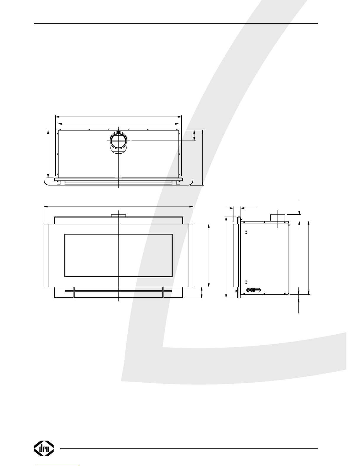
38c-1097
393
7676
862
898
340340
1064
448
79
580
52
47
524
25
Romano
Page 3

Belangrijk
•
Zorg dat er minimaal 3 mtr afvoerpijp (verticaal) met een diameter van 100 mm
aangesloten wordt op het toestel.
•
Het is niet toegestaan het toestel in de schouw te voorzien van een isolatie deken o.i.d.
•
Voordat men het toestel in gebruik neemt dient u altijd de ruit schoon te maken, dit om
inbranden van evt. verontreinigingen tegen te gaan.
Important
•
Ensure that at least 3 m. (vertical) outlet pipe, 100 mm diameter, is connected to the
appliance.
•
It is not allowed to wrap a built in appliance in any kind of isolation material.
•
Before you start using your fire, it is wise to clean the glass front.This to prevent burning in
of possible dirt into the glass.
Important
•
Assurez-vous de raccorder à l'appareil un conduit d'évacuation d'au moins 3 mètres de
haut et 100 mm de diamètre.
•
L'appareil, lors de son installation dans la cheminée, ne peut en aucun cas être recouvert
d'un matériel isolant!!!
•
Avant de mettre l'appareil en fonctionnement, il faut nettoyer soigneusement la vitre afin
d'éviter que des salissures puissent être carbonisées sur celle-ci.
Wichtig
•
Sorgen Sie dafür, daß minimal 3 Meter Abfuhrrohr (vertikal) mit einem Durchmesser von
100 mm an das Gerät angeschlossen wird.
•
Es ist nicht erlaubt ein eingebautes Gerät in Isolationsmaterial zu wickeln.
•
Bevor Sie das Gerät zum ersten Mal benützen sollten Sie das Glas reinigen. Dies um
einbrennen von eventueller Schmutz im Glas zu vermeiden.
Romano
Page 4
Romano
English
CONTENTS
13
CONTENTS
Foreword . . . . . . . . . . . . . . . . . . . . . . . . . . . . . . . . . .14
Unpacking . . . . . . . . . . . . . . . . . . . . . . . . . . . . . . . . . .14
Connection . . . . . . . . . . . . . . . . . . . . . . . . . . . . . . . .14
Important . . . . . . . . . . . . . . . . . . . . . . . . . . . . . . . . . .14
Instructions for installation . . . . . . . . . . . . . . . . . . . .14
Gas type . . . . . . . . . . . . . . . . . . . . . . . . . . . . . . . . . . .14
Important . . . . . . . . . . . . . . . . . . . . . . . . . . . . . . . . . .14
Conditions of installation . . . . . . . . . . . . . . . . . . . . .14
Positioning . . . . . . . . . . . . . . . . . . . . . . . . . . . . . . . . .14
Fitting the appliance . . . . . . . . . . . . . . . . . . . . . . . . . .15
Mantel iron . . . . . . . . . . . . . . . . . . . . . . . . . . . . . . . . .16
Connecting to a chimney flue . . . . . . . . . . . . . . . . .16
Connecting to the gas supply . . . . . . . . . . . . . . . . . .16
Adjusting for G25 natural gas . . . . . . . . . . . . . . . . . .16
Positioning the logs or white carrara stones . . . . . .17
Mounting the frame and front . . . . . . . . . . . . . . . . . .19
Remote control . . . . . . . . . . . . . . . . . . . . . . . . . . . . .20
Connecting the Receiver . . . . . . . . . . . . . . . . . . . . . .20
Replacing the batteries in the receiver . . . . . . . . . . .20
Inserting or replacing the batteries in the
remote control . . . . . . . . . . . . . . . . . . . . . . . . . . . . .20
Oxypilot . . . . . . . . . . . . . . . . . . . . . . . . . . . . . . . . . . .20
Operating instructions . . . . . . . . . . . . . . . . . . . . . . . .21
Lighting . . . . . . . . . . . . . . . . . . . . . . . . . . . . . . . . . . . .21
Remote control . . . . . . . . . . . . . . . . . . . . . . . . . . . .21
Pilot light setting . . . . . . . . . . . . . . . . . . . . . . . . . . . .21
Switching off . . . . . . . . . . . . . . . . . . . . . . . . . . . . . . . .21
Important . . . . . . . . . . . . . . . . . . . . . . . . . . . . . . . . . .21
Cleaning and Maintenance . . . . . . . . . . . . . . . . . . . . .21
Conversion instructions . . . . . . . . . . . . . . . . . . . . . .21
Removing the burner unit and the interior . . . . . . .21
Changing the elements . . . . . . . . . . . . . . . . . . . . . . .22
Replacing the base set and burner unit . . . . . . . . . .23
Adjusting the burner pressure . . . . . . . . . . . . . . . . .23
General notes . . . . . . . . . . . . . . . . . . . . . . . . . . . . . .23
Gas Safety Regulations (for installation & use) 1998
. .23
Cleaning and Maintenance . . . . . . . . . . . . . . . . . . . .23
Discoloration of walls and ceiling . . . . . . . . . . . . . . .23
Lighting the heater for the first time . . . . . . . . . . . .24
Extra protection . . . . . . . . . . . . . . . . . . . . . . . . . . . .24
Disposal . . . . . . . . . . . . . . . . . . . . . . . . . . . . . . . . . . .24
Guarantee . . . . . . . . . . . . . . . . . . . . . . . . . . . . . . . . .24
Technical data . . . . . . . . . . . . . . . . . . . . . . . . . . . . . . .49
Conditions of warranty
• This appliance has been manufactured and tested by DRU verwarming BV of The Netherlands with utmost care.
• Subject to the conditions set out on this card DRU guarantees the proper operation of this vented room heater to the original purchaser for a period of
one year after date of purchase.
• Subject to the conditions set out on this card, the cast iron combustion chamber of your DRU vented room heater carries a full guarantee to the original
purchaser for a period of ten years after date of purchase.
• The guarantee does not cover the normal wear and tear, damage due to incorrect treatment, changes of the equipment or unauthorised installations and
repairs. No liability is assumed by DRU for removal or (re)installation labor costs.
• Under no circumstances shall DRU be liable for incidental,consequential, special or contingent damages or expenses arising directly or indirectly from any
defect in the product or any component or from the use thereof.The remedies set forth herein are the exclusive remedies available to the user and are in
lieu of all other remedies. Subject to specific state laws some of the above limitations or exclusions may not apply to you.
DRU Verwarming B.V.
WARRANTY CARD
Please complete this card and keep it with the invoice to verify purchase date
and to establish the warranty period*.
Model: . . . . . . . . . . . . . . . . . . . . . . . . . . . . . . . . . . Date: . . . . . . . . . . . . . . . . . . . . . . . . . . . . . . . . . . . .
Colour: . . . . . . . . . . . . . . . . . . . . . . . . . . . . . . . . . Serial No.: . . . . . . . . . . . . . . . . . . . . . . . . . . . . . . . .
Type of Gas: Natural Gas L.P.G. (please check)
Customer: Dealer/Installer
Name . . . . . . . . . . . . . . . . . . . . . . . . . . . . . . . . . . Name . . . . . . . . . . . . . . . . . . . . . . . . . . . . . . . . . . .
Address . . . . . . . . . . . . . . . . . . . . . . . . . . . . . . . . . Address . . . . . . . . . . . . . . . . . . . . . . . . . . . . . . . . . .
City . . . . . . . . . . . . . . . . . . . . . . . . . . . . . . . . . . . City . . . . . . . . . . . . . . . . . . . . . . . . . . . . . . . . . . . . .
State . . . . . . . . . . . . . . . . . . . . . . . . . .ZIP . . . . . . State . . . . . . . . . . . . . . . . . . . . . . . . . .ZIP . . . . . . .
Province . . . . . . . . . . . . . . . . . . . . . . .P.C. . . . . . . Province . . . . . . . . . . . . . . . . . . . . . . .P.C. . . . . . .
Telephone ( . . . . . . . . . .) . . . . . . . . . . . . . . . . . . . .
*FOR SERVICE UNDER THIS WARRANTY CONTACT YOUR DEALER/INSTALLER.
DRU warrants the proper functioning of this vented roomheater if installed by a qualified installer and if used in
strict accordance with the manufacturers operating instructions
Page 5

Foreword
Dear Customer,
We would like to thank you for buying this DRU product.
Our products have been designed and produced to meet
the highest possible quality, performance and safety
requirements, allowing you to enjoy years of problem-free
use.
In this booklet you will find instructions for the installation
and use of your new appliance. Please read these
instructions and the manual carefully to familiarize yourself
with the appliance. If you require any further support,
please do not hesitate to contact your supplier.
Unpacking
Once the heater has been unpacked, all packaging should
be disposed of in the regular manner.
Connection
This appliance should be connected by a registered
installer.
Important
•
Ensure that at least 3 m. (vertical) outlet pipe, 100 mm
diameter, is connected to the appliance.
•
It is not allowed to wrap a built in appliance in any kind of
isolation material.
•
Before you start using your fire, it is wise to clean the glass
front.This to prevent burning in of possible dirt into the glass.
INSTRUCTIONS FOR INSTALLATION
Gas type
This appliance is suitable for G20 or G25 natural gas.The
manufacturer (DRU) has adjusted the appliance so that it
is suitable for G20 (20 mbar). Check that the local gas
type and pressure correspond with the specifications on
the gas type plate.The type plate is on the inside of the
casing.All regulations applicable for gas installation,
including any locally enforced regulations, should be
observed at all times.The appliance must be connected by
a qualified installer.
If the appliance is to work on G25, please follow the
instructions elsewhere in this booklet.
For the appliance to work on propane (G31) it will have
to be converted by a qualified installer.
A conversion set can be ordered through him.
Important
• Make sure that any curtains or other combustible
materials are at least 50 cm away from the heater.
• Beware! Touching hot parts of the heater can cause burns
and blisters!
• The appliance must be installed by a qualified fitter
• DO NOT use a dust filter under or on top of the casing.
• DO NOT hang wet clothes or towels etc. on the heater
to dry!
Conditions of installation
It is the law that all gas appliances are installed only by a
CORGI Registered Installer, in accordance with these
install appliances correctly could lead to prosecution. It is
in your own interest and that of safety to comply with
the law.
The installation must also be in accordance with all
relevant parts of the Local and National Building
Regulations where appropriate, the Building Regulations
(Scotland Consolidation) issued by the Scottish
Development Department , and all applicable requirements
of the following British Standard Code of Practice.
• B.S. 6891 Installation of Gas Pipework
• B.S. 5440 Parts 1 & 2 Installation of Flues and Ventilation
• B.S. 1251 Open fire place components
• B.S. 715 Metal flue pipes for gas appliances
• B.S. 6461 Part 1 installation of chimneys and flues
No additional ventilation is required for this appliance.
Positioning
• This appliance must be installed in accordance with the
current regulations and may only be used in a properly
ventilated room, to ensure that there is always sufficient
air supply.
• The appliance may only be installed against a wall made of
combustible material if the wall is protected with a
protective panel.
• Keep the connection between the pipe mouth and the
chimney duct as short and straight as possible. The gas
control block must be easily accessible.
• The minimum height of the chimney duct is 3 mtr.
• At least 3 metres of 100 mm ø (vertical) duct should be
connected to the appliance.
•
It is not allowed to wrap a built in appliance in any kind of
isolation material.
14
INSTRUCTIONS FOR INSTALLATION
Page 6
Fitting the appliance
The design of this fire is such that the casing can be
completely built in first, in a fireplace or chimney breast (of
incombustible and heat-resistant material) and the
appliance itself slid into place afterwards.Any existing
chimney should first be professionally cleaned before
connecting the appliance to it.The flue duct should be
fitted with an effective chimney cowl, to ensure a good
draught in the chimney no matter what the wind
conditions are.The type of chimney cowl and the position
of the opening must meet any applicable local standards, to
ensure it works properly.To build the casing into the
fireplace, a rectangular hole must be made that is:
min. 530 high and min. 875 wide
Allow for the depth of the heater itself (350 mm).
Construct the chimney accurately allowing for the size of
the flange on the casing.
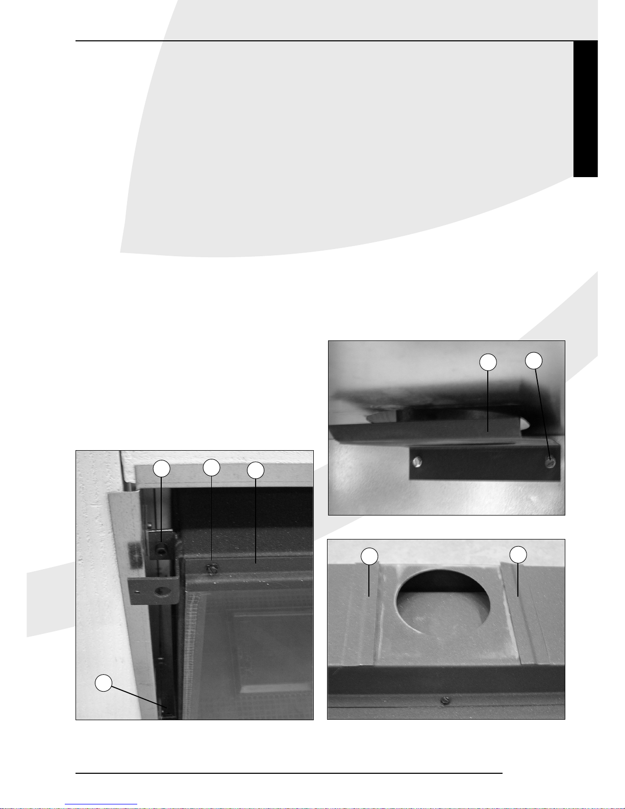
• Take out the glass pane (fig.1) by removing the glass strip
at the top (1).This is fitted with 5 self-tapping screws (2).
• Slide the interior out of the casing. by unscrewing the 4
socket-head screws (3).
• Dismantle the outlet connector (4) by removing the 2 selftapping screws (5), (fig.2).
• First slide the flue pipes into the chimney and fix them to
leave sufficient room underneath to slide the casing into
the fireplace or chimney breast.
• Place the casing in the opening and feed the gas pipe
through the slot on the right.
• Feed the flue ducts through into the outlet connector.
• Reconnect the outlet connector (4) with the 2 self-tapping
screws (5).After tightening the self-tapping screws, loosen
them 1/8 turn to make it easier to slide the sides of the
outlet connector between the slots (6) in the baffle, (fig.3).
• Slide the interior back into the casing.The outlet will
automatically be centred in the slots (6) of the baffle. Fix
the interior in place with the 4 socket-head screws (3).
• Connect the gas pipe to the gas control block and check
the connections for leaks.
The appliance has been adjusted for G20
natural gas with a pre-pressure of 20 mbar.
For use with G25 natural gas, see instructions
elsewhere in this booklet: Adjusting for G25
natural gas.
English
15
INSTRUCTIONS FOR INSTALLATION
Romano
fig. 2
fig. 3
fig. 1
3
2
1
3
4
5
6
6
Page 7

Mantel iron
A good means of supporting the brickwork above the
hearth surround is an iron mantel: a steel angle section
(e.g. 60x60x4) or a lintel.This enables a stress-free
installation of the appliance. Fit the mantel iron as
illustrated in fig. 4, allowing min. 10 mm between the top
of the appliance and the bottom of the mantel iron.
Connecting to a chimney flue
• The interior diameter of the pipe opening is 100 mm.
• Ensure that at least 3 m. (vertical) outlet pipe, 100 mm
diameter, is connected to the appliance.
• Corrosion-proof material should be used to connect the
pipe and the chimney flue.
• The chimney must be cleaned before the heater is
installed and the flue duct tested in compliance with
national guidelines.
Connecting to the gas supply
The gas control block has a 3/8" internal thread for the
gas connection.
Use an approved connecting tap with coupling in the
supply pipe (for Belgium this must be B.G.V. approved).
In addition:
• Expel the air from the supply pipes before connecting the
appliance.
• Avoid pressure on the gas control block and the pipes.
• Check all connections for gas tightness.
Adjusting for G25 natural gas
Ex works the appliance is adjusted for use with G20
natural gas.The primary aeration of the burner tray has a
ø 6.5 mm opening.To run on G25 natural gas this must be
adjusted to a ø 5.0 mm opening and the burner pressure
should be adjusted accordingly.
• Remove the vermiculite tray.
• Remove the burner tray by unscrewing the 4 self-tapping
screws (7), (fig.5).
• Unscrew the adjusting screw (8) in the airflow regulator
(9), (figs. 6 and 7).
16
INSTRUCTIONS FOR INSTALLATION
38c-1102
A
A
38c-1103
SECTION A-A
A
A
38c-1103
fig. 5
fig. 6
fig. 7
38C-1008
Mantel iron
70x50x4
Packing
5
fig. 4
7
9
8
9
Page 8

Romano
• Turn the airflow regulator 180º and tighten the adjusting
screw.The primary aeration opening is now Ø 5 mm.
• Apply the new type plate.
• Replace the burner tray with the 4 self-tapping screw (7).
• Replace the vermiculite tray.
• Set the burner pressure to 19 mbar. See page 22 for
how to set the burner pressure.
These adjustments may only be made by a qualified
installer.
Positioning the logs or white carrara stones
The appliance is supplied either with a set of logs or with
white carrara stones.
Positioning the logs
• Fill the burner tray with vermiculite (10) and distribute
evenly, (fig. 8).
• Fill the vermiculite tray with chips (11) and distribute this
evenly too, (fig. 8).
• Make sure the slot between the burner tray and the
vermiculite tray stays open.
• Make sure that no vermiculite and/or chips get on or
between the (oxypilot) pilot light burner (12) as this could
prevent the pilot light from working properly (fig. 8).
• Position the logs (fig.9) as illustrated (fig.10).
Positioning the white carrara stones
• Fill the burner tray with vermiculite (10) and distribute
evenly, (fig. 8).
• Fill the burner tray and the surrounding tray with the
white carrara stones, (figs. 11 and 12). Distribute the
stones in a single layer. Stones on top of each other will
distort the flame effect.
• Make sure that there are no stones in front of the opening
of the (oxypilot) pilot light burner (12) as this could
prevent the pilot light from working properly
(figs. 11 and 12).
• N.B.: The burner tray must always be filled
with vermiculite. This is essential to warrant
the long service life of the burner tray.
You can "play" with the flames by moving the vermiculite
and chips about on the burner bed until you have created
the desired flame effect.
Do not use any materials other than those supplied.
The supplied materials are incombustible and have been
manufactured specifically for this appliance.
Once the logs or stones are in position, the
glass pane can be replaced and fixed with the glass strip
(1) and the 5 self-tapping screws (2) (fig.1).
English
INSTRUCTIONS FOR INSTALLATION
17
fig. 8
10
12
11
Page 9

INSTRUCTIONS FOR INSTALLATION
18
A
A
A A
B
C
D
E
F
F
G
G
H
H
H
F
G
A
C
A
D
A
E
F
B
H
H
G
H
A
fig. 9
fig. 10
Page 10

Mounting the frame and front
The frame and front are packed separately to the basic set.
Fit the frame to the interior with the 4 self-tapping screws
(13), ( figs. 13 and 14).
Hang the front onto the interior with the hooks (14)
(figs. 15 and 16).
Nederlands
INSTRUCTIONS FOR INSTALLATION
19
Romano
A
A
SECTION A-A
38c-1101
fig. 16
14
fig. 12
fig. 14
fig. 11
fig. 13
fig. 15
13
14
13
12
12
Page 11

Remote control
Remote control is supplied as a standard accessory.
The heater has a freely adjustable. Batteries, with a life
expectancy of approximately one year, feed the electrical
supply.The remote control will only work if the pilot light
is lit.
Connecting the Receiver
The remote control system comprises a receiver and a
remote control, packed together in one box.The receiver
must be connected to the appliance fitting the batteries.
This is done as follows:
• Take the receiver out of the box.
• Slide the white plug of the cable onto the receiver circuit
board (fig. 17a).
• Connect the wires to the connectors on the gas control
valve.The different sized plugs correspond with the
connectors on the gas control valve.
• Open the lid.
• Insert 4 penlight batteries (type AA). Make sure they are
the right way round.
• Replace the lid.
• Place the receiver under the appliance on the floor. Make
sure that the red LED points forwards. Place the reciever
as far away from the burner tray as possible to prevent
the reciever from getting too hot.
Replacing the batteries in the receiver
• Open the door at the front.
• Take the receiver and open the cover.
The batteries are under that cover.
• Remove the old batteries and insert the new ones, making
sure that the + and – signs on the batteries correspond
with those in the holder.
Inserting or replacing the batteries in the
remote control
• Remove the cover on the back of the remote control.
• Connect a square battery (type 6LR61) to the clip.
• Fit the battery in the holder.
• Replace the cover.
NB: Do not throw old batteries in the dustbin.
They should be treated as Chemical Waste.
Oxypilot
This appliance has been fitted with an oxypilot safety
device.The oxypilot is activated in the event of flue gasses
flowing back through the baffle. The pilot light goes out
and the gas supply to the burner is shut off.The oxypilot
will also switch the fire off if the oxygen concentration in
the room in which it is installed drops too low.
Possible causes of the safety device being activated include:
• There is little or no supply of fresh air into the home
(all draughts have been excluded and ventilation openings
sealed off).
• The outlet into the flue duct is partially or completely
blocked.
• The chimney mouth was not constructed correctly, can
cause "fall winds" in the chimney duct being a possible
result.
The appliance needs a good supply of air for optimum
combustion. If there is not enough air, because all draughts
have been excluded or all means of ventilation have been
closed or shut off, for example, and/or because a
mechanical extraction system such as a cooker hood
extracts too much air, a permanent means of ventilation
must be fitted in the room in which the heater is to be
installed. If the home has a mechanical extraction system,
the flue system to which the gas fire is connected must
have a flue fan.
Please refer to the gas installation regulations and any
relevant legislation enforced locally.
The appliance can be re-ignited once the air supply and / or
flue discharge has been restored.
INSTRUCTIONS FOR INSTALLATION
20
fig. 17a
Page 12

Romano
English
OPERATIONS INSTRUCTIONS CONVERSION INSTRUCTIONS
21
OPERATING INSTRUCTIONS
Lighting
Press button A and turn to the left to the small flame .
The flame will ignite at . Check that the pilot is alight. If
that is the case, hold button A firmly pressed for another 5
seconds.Then release button A and check that the pilot
light is still burning. Now turn button A to the large
flame , which will open the main valve of the control
block. Depending on the setting of the control button B,
high or low flames will be visible.
Remote Control
The height of the flames can be regulated by remote
control, which will turn button B (fig. 17b) on the gas
control block. Press the bottom button on the remote
control for a smaller flame; press the upper button for a
higher flame. Manually adjusting button B will have the
same effect.
A certain force is required when rotating button B,
a clicking sound is quite normal.
Pilot light setting
If the heater is not in use but you would like the pilot light
to remain alight, set button A to the small flame.The gas
supply to the main burner will then be switched off.
Switching off
Turn button A to the "0" setting.The gas supply to the
burners will then be switched off.
Important
A built-in safety lock is activated when the appliance is
switched to "OFF" (closed down setting).Therefore, wait 5
minutes before relighting the heater.Within this period, do
not try to push the lighting button, as this has been
blocked by the safety lock. Do not force the button, as this
may result in damage to the mechanism.
CONVERSION INSTRUCTIONS
The appliance will have to be converted for it to be able to
run on propane (G31).
This conversion may only be carried out by a qualified
installer, who will also be able to order the required
conversion set.
Disconnect the gas supply before converting.
Remove the burner unit and the interior
To be able to change the required elements, the complete
burner unit will have to removed and the interior slid out
of the casing.To do this:
• Remove the glass pane.
• Disconnect the gas supply pipe.
• Remove the vermiculite tray.
• Remove the burner tray.
• Remove the airflow regulator! This does not have to be
replaced.
• Remove the burner mounting plate by unscrewing the selftapping screws (15), (fig.18a).
• Slide the interior out of the casing.
fig. 17b
AB
Fig. 18a
Fig. 18b
16
15
17
18
23 4
Page 13

Changing the elements
1. Outlet connector (fig. 18b and 18c)
Break and remove the semi-circle (23) of the connection
(4).
2. Main burner jet
(fig.18a)
Using an open-ended spanner remove the jet with (16)
and fit a new one.
3. Oxypilot (fig.18a)
Disconnect the pilot light hose by unscrewing the
coupling nut (17). Disconnect the ignition wire from the
electrode. Unscrew the thermocouple from the gas
control block.
Remove the oxypilot by undoing the 2 screws (18)
and fit the new oxypilot. Reconnect the pilot light hose,
the ignition wire and the thermocouple.
4. Fine adjustment jet
(fig.19)
Once the grub screw (19) has been unscrewed, the fine
adjustment jet can be twisted out of the gas control
block. Fit the new fine adjustment jet and then the grub
screw (19) in the gas control block.
CONVERSION INSTRUCTIONS
22
fig. 21
fig. 22
fig. 20
38c-1105
20
21
22
Fig. 19Fig. 18c
19
23
Page 14

Replacing the base set and burner unit
• Apply the new type plate.
• Slide the interior back into the casing.
• Replace the burner mounting plate.
• Replace the burner tray without the airflow regulator.
• Replace the vermiculite tray.
• Position either the logs or the white carrara stones.
• Replace the glass pane.
• Fit the frame and front.
Adjusting the burner pressure (fig. 20, 21 and 22)
Reconnect the gas supply to the heater and open the
new gas pipe.
On the gas control block is point of pressure
measurement where the burner pressure can easily be
measured with a manometer. Loosen the screw at the
point of pressure measurement (20) and connect the
manometer.
Remove the cover of the gas control block by removing
the screw (21).To convert the appliance to propane or
natural gas the burner pressure must be adjusted with
the pressure regulating screw (22) as specified in the
table. Replace the cover.
Ignite the pilot light. Set the thermostat to the highest
setting and adjust the burner pressure as specified in the
table. Check the gas tightness! Turn the burner off again,
remove the manometer and tighten the screw at the
point of pressure measurement.
GENERAL NOTES
Gas Safety Regulations (for installation & use) 1998
In your own interest and that of safety, it is law that
all gas appliances are installed by competent persons
in accordance with the above regulations. Failure to
install appliances correctly could lead to
prosecution.
NB: The Council of Registered Gas Installers, whose
members are identified by the emblem shown here, are all
required to work to the recognised standards.
Cleaning and Maintenance
The appliance should be inspected once a year by a
qualified company, and cleaned and/or repaired as
necessary.The inspection and maintenance must at least
ensure that the appliance is working correctly and safely.
This can be done by your own gasinstaller or a specialised
maintenance company. It is advisable to remove any dust
from the appliance several times before and during the
heating season.After a while a deposit will form on the
inside of the glass pane.This can be removed with a damp
cloth or with a non-abrasive cleaning agent (e.g. brass
polish). Do this as soon as any deposit appears, to prevent
it from burning and becoming impossible to clean. Do not
use corrosive or abrasive substances to clean the casing.
Any damage to the coating, caused by things put on or
against the casing for example, is not covered by the
guarantee.
The chimney should be inspected regularly, to check that
all flue gasses are discharged through the chimney.
Excessive accumulation of soot in the chimney should be
avoided.The soot that does form should be removed, only
ever when cold, with a brush or vacuum cleaner.The
ventilation should also be checked regularly, to make sure
there are no obstructions.
NB: When replacing the thermocouple, the coupling nut
in the gas control block should first be tightened by hand
and then tightened a quarter-turn with an open-ended
spanner.
Discoloration of walls and ceiling
Brown discoloration is an annoying problem, which is
difficult to solve. It can be caused by dust burning as a
result of poor ventilation, for example, or by cigarette
smoke or candles.
English
GENERAL NOTES
GUARANTEE REGISTRATION CARD
In order to register your guarantee, please complete and return this card(no stamp required)
Details of equipment:
Model: . . . . . . . . . . . . . . . . . . . . . . . . . . . . . . . . . . . . . Serial No.: . . . . . . . . . . . . . . . . . . . . . . . . . . . . . . . . . . . . .
Type of gas: Natural Gas L.P.G. (please tick).
Model an serial no. are to be found on data badge inside heater.
Customer: Installed by:
Name . . . . . . . . . . . . . . . . . . . . . . . . . . . . . . . . . . . . . Name . . . . . . . . . . . . . . . . . . . . . . . . . . . . . . . . . . . . . . . . .
Address (of installation) . . . . . . . . . . . . . . . . . . . . . . . Address . . . . . . . . . . . . . . . . . . . . . . . . . . . . . . . . . . . . . . .
Post Code . . . . . . . . . . . . . . . . . . . . . . . . . . . . . . . . . . Post Code . . . . . . . . . . . . . . . . . . . . . . . . . . . . . . . . . . . . .
Tel. No. . . . . . . . . . . . . . . . . . . . . . . . . . . . . . . . . . . . . Tel. No. . . . . . . . . . . . . . . . . . . . . . . . . . . . . . . . . . . . . . . . .
Appliance installed in . . . . . . . . . . . .(Office, Church, etc.)
Is appliance replacing alternative fuel: Solid Fuel Oil Electricity (please tick).
If replacing existing balanced flue heater make of original
Date of installation
N.B.Where more than one appliance installed, please complete all cards and return in envelope using freepost address on reserve.
Completion of this card in no way affects your statutory rights
Thank you DRUGASAR LIMITED
Page 15

These problems can be avoided by ensuring that the room
the heater is in is properly ventilated.A good guideline for
ventilation is:
New buildings : 3.24 m
3
/ hour per m2floor
surface of the room.
Existing buildings : 25.20 m
3
/ hour for a room.
Use candles and oil lamps as little as possible, keeping the
wick as short as possible.While they Enhance the
atmosphere, candles and oil lamps also cause the
formation of large quantities of unhealthy soot particles in
your home. Cigarette and cigar smoke contains tar, which
upon heating will precipitate on cold or damp walls. If you
have a newly cemented chimney or have had any other
reconstructions / renovations done, you are advised to
wait at least 6 weeks before lighting your fire, to allow the
walls, floor and ceiling to dry out completely.
Lighting the heater for the first time
There can be an unpleasant smell when you light the
heater for the first time.This is caused by the varnish
evaporating and will disappear after a few hours.We
therefore advise you,on initial use, to heat the appliance at
the highest setting while ventilating the room it is installed
in well.
Extra protection
This heater meets the normal safety standards regarding
surface temperatures, but physical contact with heated
surfaces should be avoided where possible. An additional
guard is recommended to protect young children and
elderly, infirmed or handicapped people.
Before you start using your fire, it is wise to clean the glass
front.This to prevent burning in of possible dirt into the glass.
Disposal
When replacing or otherwise removing the appliance, it
should be disposed of in compliance with current
regulations.
Shut off the connecting tap with coupling before
commencing disassembly. Undo the coupling between the
connecting tap and the appliance.The whole appliance can
now be disassembled and removed.
Guarantee
Please complete the enclosed REGISTRATION CARD and
post it in an envelope (no stamp required) to the address
below within 5 days of purchase.
DRUGASAR LIMITED
FREEPOST
DEANS ROAD
SWINTON
MANCHESTER M27 1 BX
Please retain the GUARANTEE CARD (page 13) for your
own reference.The guarantee will become effective upon
receipt by DRUGASAR Limited of the fully completed
registration card.
PLEASE SEND IN AN
ENVELOPE
DRUGASAR LIMITED
FREEPOST
DEANS ROAD
SWINTON
MANCHESTER M27 1 BX
DRUGASAR, GAS HEATING FOR PEOPLE WHO DON’T HAVE MONEY TO BURN.
GENERAL NOTES
Page 16

Romano
TECHNISCHE GEGEVENS,TECHNICAL DATA, DONNÉES TECHNIQUES,TECHNISCHEN DATEN
49
Romano
Gassoort,Type of gas, Sorte de gaz, Gassorte G20
Voordruk, Pression, Pression, Gasdruck mbar 20
Branderdruk, Burner pressure, Pression de brûleur, Brennerdruck mbar 13
Nom. Belasting (Hs), Nom. Load (Hs), Puissance calorifique (Hs), Nom. Belastung (Hs) kW 6,90
Nom. Belasting (Hi), nom. Load (Hi), Puissance calorifique (Hi), Nom. Belastung (Hi) kW 6,20
Nom.Vermogen, Nom. Output, Puissance nominale, Nennleistung kW 4,30
Verbruik volstand, Gas consumption on full output, consommation de gaz plein régime, Gasverbrauch Vollstand L/h 651
Verbruik kleinstand, Gas consumption on low output, Débit de gaz débit réduit, Gasverbrauch Kleinstand L/h 267
Branderspuitstuk, burner injector, injecteur brûleur, Brennerdüse mm ø 2,10
Kleinstelspuitstuk, low setting injector, injecteur débit réduit, Kleinstelldüse mm ø 1,35
Gassoort,Type of gas, Sorte de gaz, Gassorte G25
Voordruk, Pression, Pression, Gasdruck mbar 25 20
Branderdruk, Burner pressure, Pression de brûleur, Brennerdruck mbar 19 19
Nom. Belasting (Hs), Nom. Load (Hs), Puissance calorifique (Hs), Nom. Belastung (Hs) kW 6,90 6,90
Nom. Belasting (Hi), nom. Load (Hi), Puissance calorifique (Hi), Nom. Belastung (Hi) kW 6,20 6,20
Nom.Vermogen, Nom. Output, Puissance nominale, Nennleistung kW 4,30 4,30
Verbruik volstand, Gas consumption on full output, consommation de gaz plein régime,
Gasverbrauch Vollstand L/h 747 747
Verbruik kleinstand, Gas consumption on low output, Débit de gaz débit réduit
Gasverbrauch Kleinstand L/h 271 271
Branderspuitstuk, burner injector, injecteur brûleur, Brennerdüse mm ø 2,10 ø 2,10
Kleinstelspuitstuk, low setting injector, injecteur débit réduit, Kleinstelldüse mm ø 1,35 ø 1,35
Gassoort,Type of gas, Sorte de gaz, Gassorte G31
Voordruk, Pression, Pression, Gasdruck mbar 37 NL:30 DE:50
Branderdruk, Burner pressure, Pression de brûleur, Brennerdruck mbar 28
Nom. Belasting (Hs), Nom. Load (Hs), Puissance calorifique (Hs), Nom. Belastung (Hs) kW 6,90
Nom. Belasting (Hi), nom. Load (Hi), Puissance calorifique (Hi), Nom. Belastung (Hi) kW 6,20
Nom.Vermogen, Nom. Output, Puissance nominale, Nennleistung kW 4,20
Verbruik volstand, Gas consumption on full output, consommation de gaz plein régime,
Gasverbrauch Vollstand L/h 255
Verbruik kleinstand, Gas consumption on low output, Débit de gaz débit réduit,
Gasverbrauch Kleinstand L/h 147
Branderspuitstuk, burner injector, injecteur brûleur, Brennerdüse mm ø 1,40
Kleinstelspuitstuk, low setting injector, injecteur débit réduit, Kleinstelldüse mm ø 1,20
Page 17

50
Page 18

51
Romano
Page 19

 Loading...