

Dru Pronto G25, Pronto G20 Instructions For Installation Manual
Pronto
G20/G25
English
Instructions for installation (GB / IE)
Please retain this document carefully
UKUK
95901302UK Install_G20.indd 195901302UK Install_G20.indd 1 2-2-10 14:282-2-10 14:28

English
PRONTO - INSTRUCTION FOR INSTALLATION
Inhoudsopgave
Preface 3
1. Introduction 3
2.
CE declaration 3
3.
Safety 4
3.1
General 4
3.2
Regulations 4
3.3
Precautions / safety instructions during installation 4
4. Instructions 4
5.
Removing the packaging 4
6.
Installation 5
6.1
Regulations 5
6.2
Type of gas 5
6.3
Gas connection 5
6.4
Placement of the appliance 5
6.5
Flue gas discharge / combustion air supply system 6
6.6
Connecting gas 10
6.7
Setting the appliance 10
6.8
Placing the wood set 11
6.9
Panes 12
7.
Operation 14
7.1
Receiver 15
7.2
Placing / replacing the batteries 16
8.
Final check 16
8.1
Gasstightness 16
8.2
Gas pressure / pre-pressure 16
8.3
Ignition pilot and main burner 16
8.4
Flame image 17
9.
Maintenance 17
10
Delivery 17
11.
Malfunctions 18
Appendix 1
Appendix 2
Appendix 3
Parts included with the delivery 20
Technical data 20
Parts 20
2
UK
95901302UK Install_G20.indd 295901302UK Install_G20.indd 2 2-2-10 14:282-2-10 14:28

PRONTO - INSTRUCTION FOR INSTALLATION
Preface
DRU, a manufacturer of gas heating appliances, develops and produces products that comply with the highest quality, performance and safety requirements.
This guarantees that the user will be able to enjoy using his product for many years to come.
This appliance has a CE marking, which means that it complies with the essential requirements of the European gas
appliance directive.
As an installer, you must be competent in the fi eld of atmospheric gas heating.
Two manuals are supplied with the appliance: the installation manual and the user manual.
The installation manual will give you the information you need to install the appliance in such a way that it will operate properly and safely.
This manual discusses the installation of the appliance and the regulations that apply to the installation. In addition,
you will fi nd technical data for the appliance and information on maintenance, any malfunctions that might occur
and their possible causes.
Please carefully read and use this installation manual.
The following symbols are used in the manual to indicate important information:
Work to be performed
➠
!Tip
Suggestions and recommendations
!Caution
You will need these instructions to prevent problems that might occur during installation and/or use.
Caution
You need these instructions to prevent re, personal injury or other serious damages.
After delivery, you should give the user manual and this installation manual to the user.
English
1. Introduction
Pronto is a suspended atmospheric gas heating appliance.
This Pronto version is suitable for natural gas.
The Pronto is a closed appliance. A closed appliance does not extract the combustion air from the living environment, but from outside. This is done through a combined fl ue gas discharge system / combustion air supply system.
In this concentric system the outer pipe serves as air supply and the inner pipe as fl ue gas discharge.
This system can be installed through the wall, or through the roof.
The concentric system can be supplied in the colour of the appliance.
The appliance is supplied with a wireless remote control that works on batteries.
2. CE declaration
We hereby declare that the design and construction of DRU’s atmospheric gas heating appliance comply with the
essential requirements of the Gas Appliance Directive.
This declaration will lose its validity if adjustments are made to the appliance, without prior written permission by
DRU.
Product:
Type:
Applicable EEC directives: 90/396/EEC
Applied harmonized standards: NEN-EN-613
NEN-EN-613/A1
Internal measures by the company guarantee that appliances produced in series comply with the essential requirements of the prevailing EEC directives and the standards derived from them.
M.J.M Gelten
Dru verwarming B.V.
Postbus 1021, 6920 BA Duiven
Ratio 8, 6921 RW Duiven
www.dru.nl
atmospheric gas heating appliance
PRONTO
3
UK
95901302UK Install_G20.indd 395901302UK Install_G20.indd 3 2-2-10 14:282-2-10 14:28

English
PRONTO - INSTRUCTION FOR INSTALLATION
3. Safety
3.1 General
Caution
- Carefully read this chapter on safety, before you start performing installation or maintenance work;
Please observe the general regulations and the precautions/safety instructions in this manual.
3.2 Regulations
Please install the appliance in accordance with the applicable national, local and constructional (installation) regulations.
3.3 Precautions / safety instructions during installation
Carefully follow the following precautions/safety regulations:
you should only install and maintain the appliance if you are a competent installer in the eld of atmospheric gas hea-
➠
ting:
do not make any changes to the appliance;
➠
only use the ue gas discharge / combustion air supply system supplied by DRU;
➠
suspend the appliance from a wall of incombustible and heat resistant material
➠
take into account the minimum required free space of 500 mm at both sides of the appliance, as well as above the ap-
➠
pliance for the bene t of the appliance’s heat discharge.
suspend the appliance at least 300 mm above the oor;
➠
mount the appliance using the wall bracket supplied;
➠
do not cover the appliance and the discharge material and/or do not wrap it in an insulation blanket or any other ma-
➠
terial;
make sure that combustible objects and/or materials have a distance from the appliance of at least 500 mm;
➠
only ever use the supplied wood set;
➠
place the wood set exactly as described;
➠
make sure the pilot burner and the space around it is kept free;
➠
avoid dirt in gas pipes and connections;
➠
place a gas tap under the appliance
➠
check the connections for gastightness before using the appliance;
➠
use heat resistant electrical connectors;
➠
place the electrical connectors in such a way that they are free from the appliance;
➠
replace torn or broken panes;
➠
do not ignite the appliance until it is fully installed.
➠
4. Instructions
Observe the following items during installation in order to guarantee a proper and safe operation of the appliance:
avoid that the ignition cable runs over the receiver;
➠
avoid that the ignition cable touches or crosses the antenna;
➠
avoid that the ignition cable runs over and/or alongside metal parts, in order to prevent weakening of the spark;
➠
avoid damaging the panes during removal/placing;
➠
clean the panes before you use the appliance, in order to prevent dirt from burning in the glass.
➠
5. Removing the packaging
Note the following items when removing the packaging:
Check the appliance for damages during transport.
➠
If necessary, contact DRU Service.
➠
Follow the procedure below when removing the packaging:
Remove the top box
➠
Remove the decorative frames and the front pane (see section 6.9.1.1)
➠
The appliance can now be set up straight by lifting the top side
➠
For suspending the appliance, see section 6.4
➠
4
UK
95901302UK Install_G20.indd 495901302UK Install_G20.indd 4 2-2-10 14:282-2-10 14:28
PRONTO - INSTRUCTION FOR INSTALLATION
38c-1411
Fig. 2Fig. 1
After removing the packaging, you should have the following components:
-
Socket spanner; you will fi nd it in the space between the assembly frame and the combustion chamber;
-
Box with parts; you will fi nd it in the combustion chamber.
Remove the box containing parts from the combustion chamber.
In appendix 1 / table 4 you can see which parts you should have after removing the packaging.
Contact DRU Service if you do not have all the parts after you fi nished removing the packaging.
Dispose packaging in accordance with local regulations.
English
6. Installation
Read this manual carefully to ensure a proper and safe operation of the appliance.
!Caution
Install the appliance in the order described in this chapter.
6.1 Regulations
Observe the applicable (installation) regulations.
Observe the regulations/instructions in this manual.
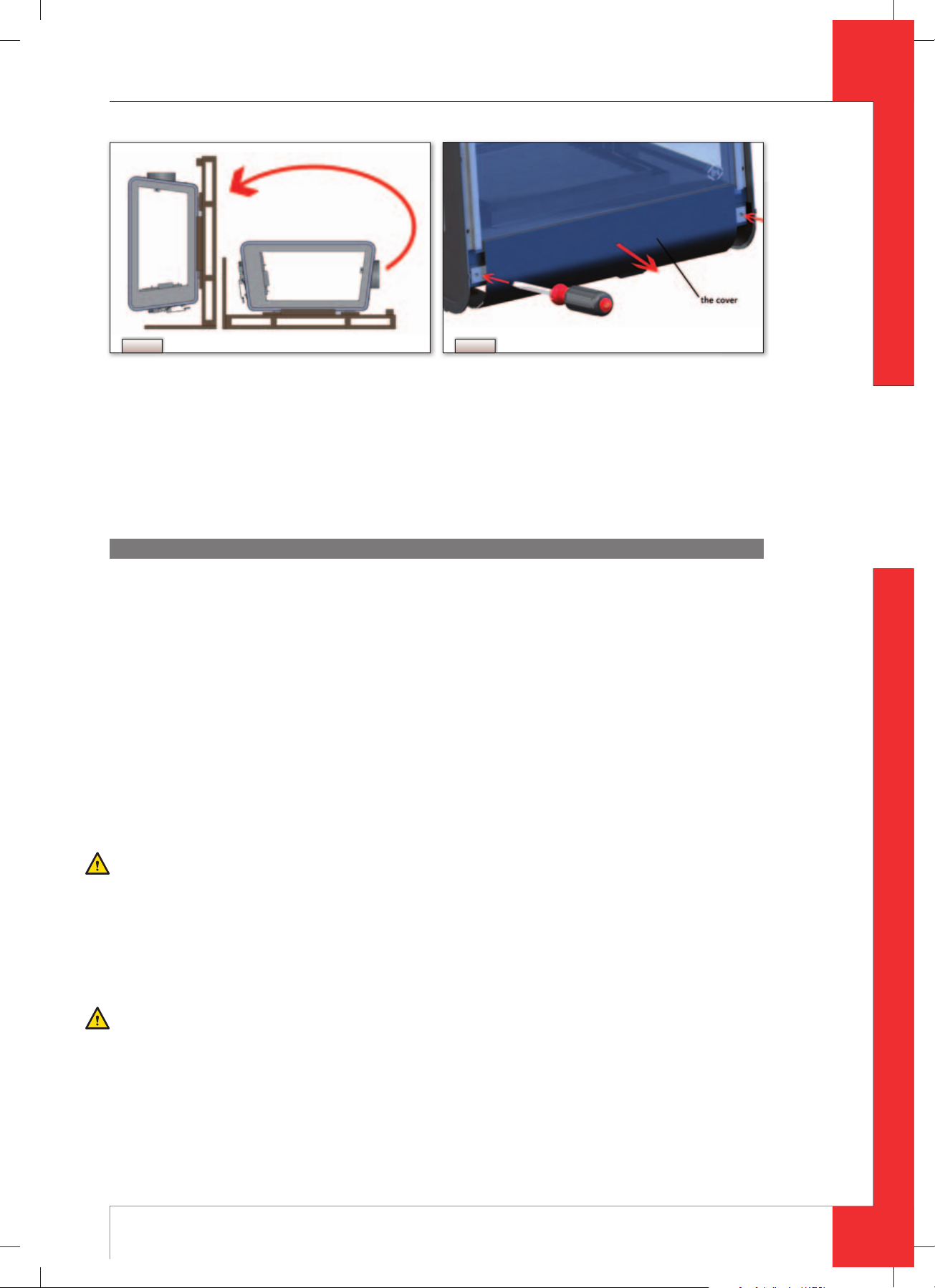
6.2 Type of gas
The type plate indicates for which type of gas, gas pressure and for which country this appliance is intended. The type
plate is located at the inside of the small ornamental cover.
Remove the small cover at the underside of the front pane by unscrewing the bolt at the left and right side. After
removing the cover you can see the type plate (see
6.3 Gas connection
Place a gas tap in the gas connection, under to the appliance.
Caution
Avoid dirt in the gas pipe and in the connections.
The following requirements apply to the gas connection:
use a gas pipe with the correct dimensions, so that no pressure loss can occur:
the gas tap should have the CE marking;
you should always be able to reach the gas tap.
Fig. 2).
6.4 Placement of the appliance
Place the appliance as follows:
Caution
- Suspend the appliance from a wall of incombustible and heat resistant material;
- Take into account the minimum required free space of 500 mm at both sides of the appliance, as well as above the
appliance for the benefi t of the appliance’s heat discharge;
- Suspend the appliance at least 300 mm above the fl oor;
- Make sure that combustible objects and/or materials have a distance from the appliance of at least 500 mm;
- Do not make any changes to the appliance.
5
UK
95901302UK Install_G20.indd 595901302UK Install_G20.indd 5 2-2-10 14:282-2-10 14:28
English
PRONTO - INSTRUCTION FOR INSTALLATION
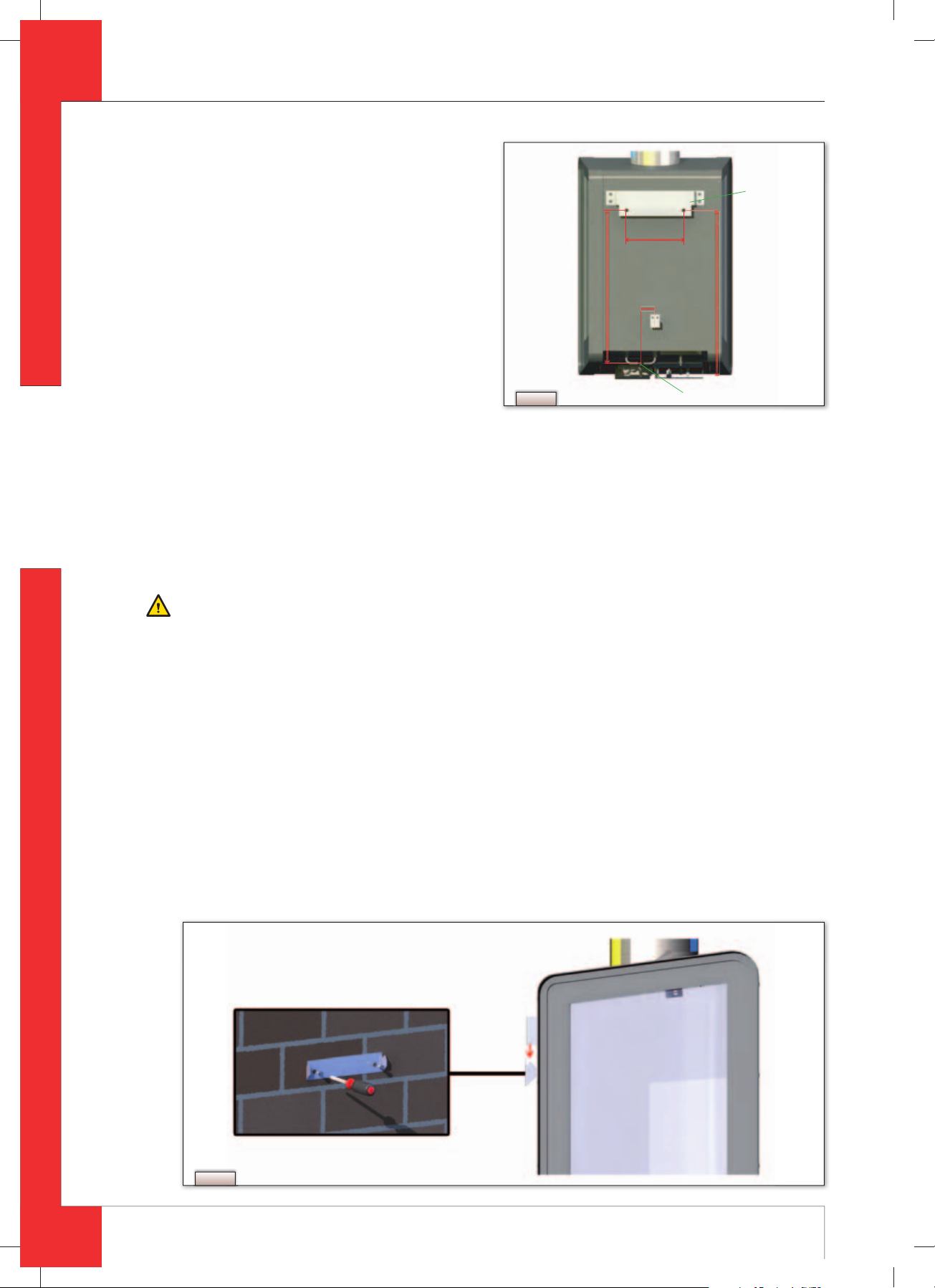
Determine the location of the appliance; the dimen-
➠
sions can be found in
Provide a gas connection at the location. For details,
➠
see section 6.3.
Make a duct for the ue gas discharge/combustion
➠
air supply system with the following diameters. For
details, see section 6.5 and
- Ø160 mm for a wall duct through incombustible
material;
-
Ø 250 mm for a wall duct through combustible
Fig. 3.
Fig. 5.
180mm
505mm
565mm
70mm
material;
-
Ø160 mm for a roof duct through incombustible
material;
-
Ø 250 mm for a roof duct through combustible
material.
Fig. 3
Gas connection
Connect the appliance to the wall using the wall
bracket and the wedge bolts supplied; see
Fig. 4
6.5 Flue gas discharge / combustion air supply system
6.5.1 General
The appliance is of the C11/C31 type.
The appliance is connected to a combined fl ue gas discharge/combustion air supply system, hereafter referred to
as the concentric system.
The passage to the outside can be made with a wall duct (see section 6.5.2) or with a roof duct (see section 6.5.3).
If necessary, you can also use an existing discharge channel (see section 6.5.4).
Wall bracket
Caution:
- Only use the concentric system supplied by DRU (Ø100 / Ø150 mm). This system was tested in combination with the
appliance;
DRU cannot guarantee a proper and safe operation of other systems and cannot accept liability for these systems.
For connecting to an existing chimney fl ue you should only use the installation set supplied by DRU.
Always place the concentric system at a minimum distance of 500 mm from combustible objects and/or materials
Maintain a distance of at least 50 mm between the outside of the concentric system and the walls and/or the ceiling.
If the system is built in (for instance) a cove, it should be made with incombustible material all around it.
The concentric system is constructed from (the discharge stump of) the appliance.
If structural circumstances require that the concentric system is placed fi rst, the appliance can later be connected
with a telescopic pipe piece.
!Tip DRU does not recommend placing the telescopic piece, because this visible pipe piece cannot be supplied in colour
and does not really combine well with the appliance.
Fig. 4
6
UK
95901302UK Install_G20.indd 695901302UK Install_G20.indd 6 2-2-10 14:282-2-10 14:28
PRONTO - INSTRUCTION FOR INSTALLATION
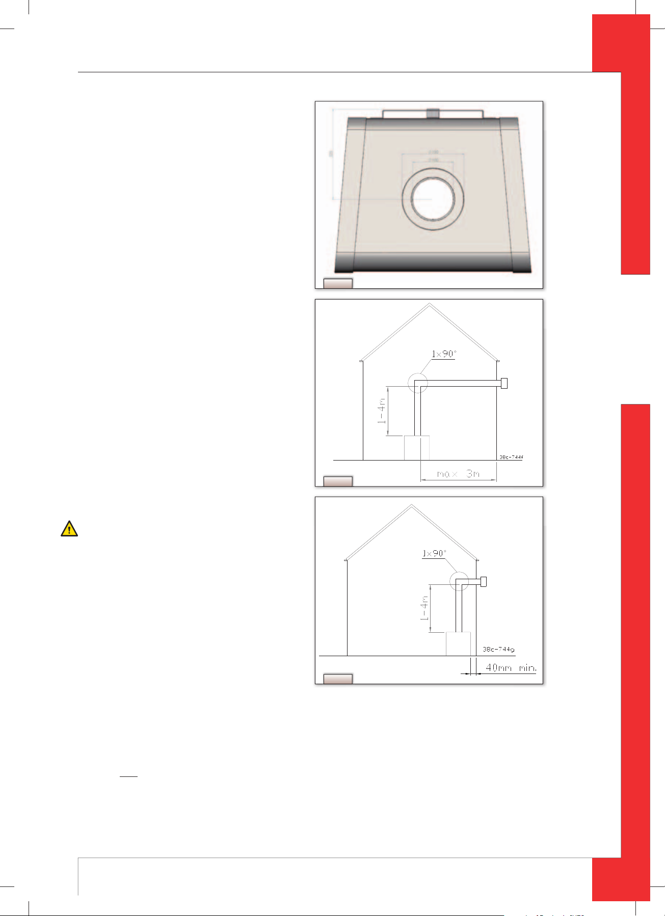
6.5.2 Application with wall duct
Construction of concentric system with
6.5.2.1
wall duct
The concentric system with wall duct has to comply
with the following conditions (see
- First, a concentric pipe of at least 1 meter should be
connected vertically to the appliance;
- The total vertical pipe length can have a maximum
of 4 meters;
- On the vertical part a bend of 90° is connected;
- The total horizontal pipe length can have a maxi-
mum of 3 meters (wall duct excluded).
Fig. 2):
The construction of the concentric system allows
the following 2 confi gurations:
1)
minimum 1 meter and maximum 4 meters of ver-
tical pipe length combined with a 90°
maximum 3
wall duct (see
When using this application, you must remove
the air inlet guide (see section 6.7). The baffl e will
not be placed.
2)
minimum 1 meter and maximum 4 meters of ver-
tical pipe length combined with a 90°
wall duct (i.e., no horizontal part, see
When using the confi guration, you will not have
to do anything: you do not have to remove the air
inlet guide or place the baffl e.
meters horizontal pipe length and a
Fig. 6).
6.5.2.2 Placing concentric system with wall
duct
Place the concentric system as follows:
Build the system up
Caution
- Maintain a distance of at least 50 mm between
the outside of the concentric system and the walls
and/or the ceiling. If the system is built in (for instance) a cove, it should be made with incombustible material all around it.
- from (the connection stump of) the appliance.
- Use heat-resistant isolation material when pas-
sing through combustible material;
- The rosette (mounting inner plate) of the wall
duct is too small to seal the Ø
when passing through combustible material.
That is why you should fi rst apply a suffi ciently
large heat-resistant intermediate plate to the wall.
Then, the rosette is mounted on the intermediate
plate.
250 mm opening
Fig. 5
bend and a
English
bend and a
Fig. 7).
Fig. 6
Fig. 7
!Caution
Some heat-resistant isolation materials contain volatile components that will spread an unpleasant smell for a pro-
longed time; these are not suitable.
Build the system up from (the connection stump of) the appliance.
➠
Connect the (lacquered) concentric pipe pieces and the (lacquered) bend.
➠
On each connection, apply a (lacquered) clip binding with silicon sealing ring.
➠
Use a parker to x the clip binding to the pipe on locations that are unreachable after installation.
➠
Apply su cient clamps, so that the weight of the pipes does not only rest on the appliance.
➠
Determine the remaining length of the wall duct.
➠
Make sure the wall duct has the right dimensions.
➠
7
UK
95901302UK Install_G20.indd 795901302UK Install_G20.indd 7 2-2-10 14:282-2-10 14:28

English
PRONTO - INSTRUCTION FOR INSTALLATION
!Caution
- Make sure that the right insertion length is maintained;
- Place the wall duct with the groove/folded seam at the top;
- Make sure the horizontal concentric pipe pieces are sloping towards the wall duct, in order to prevent rain water
from entering.
Mount the rosette (mounting inner plate); if necessary, on a heat resistant intermediate plate when passing through
➠
combustible material
Attach the wall duct from the outside with four screws in their respective holes.
➠
6.5.3 Application with roof duct
6.5.3.1 Construction of concentric system with roof duct
- The concentric system with roof duct has to comply with the following conditions:
- The construction of the chosen system has to be allowed. (See the procedure described below);
First, a concentric pipe of at least 1 meter should be connected vertically to the appliance.
Depending on the construction of the concentric system, the appliance is set by placing the baffl e and/or removing
the air inlet guide.
In the following procedure you can see how the allowability of a concentric system can be determined and which
settings are needed.
Determine the following data:
➠
The number of bends required (no distinction is made between 45° and 90° bends);
The total number of meters of horizontal pipe length;
The total number of meters of vertical and/or sloping pipe length.
These data will help you determine whether the concentric system is allowed by using Table 1.
In Table 2 you can read which setting is required for the appliance.
Follow the procedure described below:
In the rst 2 columns of Table 1, search the number of bends required and the total horizontal pipe length:
➠
In the 3
➠
If you end up in a box with the letter A, B, C or D, the concentric system chosen by you is allowed.
➠
Use Table 2 to determine which conditions apply for the ba e and/or the air inlet guide (for placing/setting see section
➠
rd
column of Table 1, search the total vertical and/or sloping pipe length.
6.7).
Examples
To clarify, we will give 2 examples to determine the allowability of a concentric system and the conditions for setting
the appliance.
In Table 1 the route to be followed is indicated by arrows. The result is indicated by a red frame surrounding the
box.
Example 1
1)
2 bends
2)
3 meters horizontal
3)
8 meters vertical/sloping
Construction of this concentric system is allowed.
Situation B applies for setting the appliance
Example 2
1)
3 bends
2)
4 meters horizontal
3)
9 meters vertical/sloping
Construction of this concentric system is not allowed.
8
UK
95901302UK Install_G20.indd 895901302UK Install_G20.indd 8 2-2-10 14:282-2-10 14:28
 Loading...