

Page 1

INSTALLATIEVOORSCHRIFT EN GEBRUIKERSHANDLEIDING NL/BE
INSTRUCTIONS FOR INSTALLATION AND OPERATION GB/IE
INSTALLATIONSVORSCHRIFT UND GEBRAUCHSANWEISUNG DE/AT/BE/LU/CH
INSTRUCTIONS D’INSTALLATION ET MODE D’EMPLOI FR/BE/LU/CH
PASSEO
Bewaar dit document zorgvuldig
Please retain this document carefully
Bewahren Sie dieses Dokument sorgfältig auf
Conservez soigneusement cette notice
957.578.08
DRU VERWARMING B.V.
HOLLAND
Page 2
Page 3

Passeo
Belangrijk
• Het toestel moet worden uitgerust met een bedieningsluik (meegeleverd),lees de instructies
hier voor op pagina 4.
• De boezem dient ontlucht te worden, evt met de beschikbare DRU ontluchters (2x) of anders
door openingen of roosters met een minimale gezamelijke doorlaat van 200 cm
2
.
• Zorg er voor dat de randen bij strakke inbouw mooi afgewerkt worden want deze komen in
het zicht, zorg er tevens voor dat men niet op of over de randen stuckt.
• Let erop dat u bij het in- en uitnemen van het glasraam de boezem of de schouw niet
beschadigd.
• Het is niet toegestaan het toestel te voorzien van een isolatie deken of op enige wijze in te
pakken of af te dekken.
• Voordat men het toestel in gebruik neemt dient u altijd de ruit schoon te maken, dit om
inbranden van evt. verontreinigingen, zoals vingerafdrukken tegen te gaan.
• Dit toestel mag uitsluitend met het door DRU geleverde afvoermateriaal Ø150/Ø100
geïnstalleerd worden.
• De ruimte onder het toestel dient vrij te blijven, om een eventuele werking van het
drukvereffeningsluik te waarborgen.
• Let op: Om een goede ontsteking te waarborgen moet de ontstekingskabel zoveel mogelijk
vrij liggen van de metalen delen van het toestel. Draai deze dus niet om de gas-, waakvlam-,
of thermokoppelleiding.
• De waakvlambrander en de overloopbrander moeten ten allen tijde worden vrijgelaten
zodat de vlammen niet worden geblokkeerd.
• De positionering van de houtblokken is geen vrijblijvend advies maar moet exact conform de
beschrijving worden uitgevoerd. Indien dit niet gebeurt zou dit tot gevaarlijke situaties kunnen
leiden.
Important
• The appliance should be fitted with a service flap (provided), please read the instructions on
page 16.
• The chimney breast should be ventilated, e.g. with the DRU vents available (2x) or
alternatively with openings or grilles with a minimum total free vent area of 200 cm
2
.
• If the fire is to be built in, flush with the wall,make sure the edges are neatly finished and not
plastered over as they will remain visible.
• Be careful not to damage the chimney breast or fireplace when placing or removing the
glass pane.
• The appliance must not be fitted with an insulation blanket or in any other way wrapped or
covered.
• Always clean the glass pane before using the fire to avoid marks such as fingerprints burning
in.
• This appliance may only be installed using the Ø150/Ø100 flue material supplied by DRU.
• The space under the heater must be kept free to ensure the by-pass valve will function
correctly if necessary.
• NB:
To ensure the ignition works properly, the ignition wire must come into as little contact as
possible with the metal parts of the heater and should therefore not be wound round the gas
or pilot-light pipes or the thermocouple.
• The pilot burner and the overflow burner must always be kept clear of obstruction so that the
flames remains unblocked at all times.
• It is vitally important that you adhere to the correct positioning of the logs as specified. Failure
to do this may result in an unsafe situation.
Page 4

Wichtig
• Das Gerät muss mit einer Bedienungsluke (mitgeliefert) ausgerüstet werden.Lesen Sie hierzu
die Instruktionen auf Seite 28.
• Der Kaminüberbau muss entlüftet werden, evtl. mit den verfügbaren DRU-Entlüftern (2x), oder
aber mit Öffnungen auf Rosten mit einem minimalen Gesamtdurchlass von 200 cm
2
.
• Sorgen Sie dafür, dass die Ränder bei einem straffen Einbau schön verarbeitet werden, denn
diese sind sichtbar. Sorgen Sie ausserdem dafür, dass nicht auf oder über die Ränder verputzt
wird.
• Achten Sie darauf, dass Sie beim Ein- und Ausheben des Glasfensters den Kaminüberbau oder
den Umbau nicht beschädigen.
• Es ist nicht erlaubt, das Gerät mit einer Isolationsdecke zu versehen, oder es, auf welche Weise
dann auch, ein zu packen, oder ab zu decken.
• Bevor man das Gerät in Gebrauch nimmt, muss erst die Scheibe gesäubert werden. Dies, um
Einbrennen von eventuelle Verunreinigungen, wie Fingerabdrücke zu verhindern.
• Dies Gerät darf nur mit dem von DRU gelieferten Abfuhrmaterial Ø150/Ø100 installiert
werden.
• Der Platz unter dem Gerät muss frei bleiben, um eine eventuelle Tätigkeit der
Druckausgleichsluke gewährleisten zu können.
• Achtung: Um Garantie für eine gute Zündung zu gewährleisten, muss das Zündkabel
möglichst von den Metallteilen des Gerätes frei liegen Drehen Sie dieses also nicht um die
Gas-, Zündflammen-, oder Thermokupplungsleitung.
• Der Zündflammenbrenner und der Überlaufbrenner müssen immer freigelassen werden, so
dass die Flammen nicht blockiert werden.
• Die Positionierung der Holzblöcke ist kein freibleibender Rat, sondern muss exakt nach der
Beschreibung ausgeführt werden. Falls dies nicht geschieht, kann es zu gefährlichen
Situationen führen.
Important
• L’appareil doit être équipé d’un panneau de commande (fourni) ; lire à ce propos les
instructions page 40.
• Le manteau doit être ventilé, éventuellement à l’aide de ventilateurs DRU (2x) ou par le biais
d’ouvertures ou de grilles laissant un passage minimum de 200 cm
2
.
• Veiller à ce que, pour un encastrement ajusté, les bords soient finis proprement car ils se
voient bien ; veillez également à ne pas plâtrer sur les bords.
• Veiller à ne pas endommager le manteau ou la cheminée en retirant et remettant la vitre.
• Il n’est pas permis d’isoler l’appareil, de l’emballer ou le recouvrir d’une façon ou d’une
autre.
• Il est impératif de nettoyer la vitre avant d’utiliser l’appareil, ceci afin d’éviter la combustion
d’éventuelles saletés comme les traces de doigt.
• Cet appareil doit être installé en utilisant exclusivement les tuyaux d’évacuation Ø150/Ø100
fournis par DRU.
• Il faut laisser l’espace libre sous l’appareil pour permettre à la soupape de dérivation de
fonctionner si nécessaire.
• Attention: Pour garantir un bon allumage, veillez à écarter le câble d’allumage des parties
métalliques de l’appareil. N’entourez donc pas ce câble autour du conduit de gaz, de la
veilleuse ou du thermocouple.
• La veilleuse et la rampe de traverse doivent toujours être dégagés afin de ne pas bloquer les
flammes.
• Le positionnement des bûches n'est pas laissé à une libre appréciation mais doit être
exactement exécuté conformément à la description. Un non respect de cette obligation
pourrait provoquer des situations dangereuses.
Page 5

Nederlands
Passeo
5
Page 6

INSTRUCTIONS
6
Hierbij verklaren wij dat de DRU modellen Passeo in overeenstemming zijn met het CE typeonderzoekscertificaat E 1490 en dat zij voldoen aan de Europese richtlijn inzake gastoestellen
90/396/EEC.
We here by declare that the DRU models Passeo are in conformity with the types as described
in EC type-certificate E 1490 and that they are in compliance with the European Council gas
appliance directive 90/396/EEC.
Hiermit erklären wir, dass die DRU-Modelle Passeo mit dem CE Typen-Untersuchungszertifikat
übereinstimmen E 1490 und dass diese den Richtlinien für Gasgeräte 90/396/EEG entsprechen.
Nous déclarons par la présente que les modèles DRU Passeo sont conformes au certificat
d'examen de type CE E 1490 et qu’ils satisfont à la directive européenne relative aux appareils
à gaz 90/396/CEE.
Page 7
Nederlands
INHOUD
Belangrijk . . . . . . . . . . . . . . . . . . . . . . . . . . . . . . . . . . .2
Woord vooraf . . . . . . . . . . . . . . . . . . . . . . . . . . . . . . .2
Uitpakken . . . . . . . . . . . . . . . . . . . . . . . . . . . . . . . . . . .2
Aansluiten . . . . . . . . . . . . . . . . . . . . . . . . . . . . . . . . . .2
Installatievoorschrift . . . . . . . . . . . . . . . . . . . . . . . . . .2
Gassoort . . . . . . . . . . . . . . . . . . . . . . . . . . . . . . . . . . .2
Belangrijk . . . . . . . . . . . . . . . . . . . . . . . . . . . . . . . . . . .2
Plaatsen van het toestel . . . . . . . . . . . . . . . . . . . . . . . .2
Bedieningsluikje . . . . . . . . . . . . . . . . . . . . . . . . . . . . . .4
Aansluitmogelijkheden . . . . . . . . . . . . . . . . . . . . . . . . .4
Voorbereidingen voor het plaatsen van
het in- en uitlaatsysteem . . . . . . . . . . . . . . . . . . . . . . .5
Geveldoorvoer met concentrische pijpen . . . . . . . . .5
Dakdoorvoer met concentrische pijpen . . . . . . . . . . .5
Bestaande schoorsteen . . . . . . . . . . . . . . . . . . . . . . . .6
Instellingen restrictieschuif en luchtinlaatgeleider . . .6
Aansluiting van de gastoevoer . . . . . . . . . . . . . . . . . . .6
Plaatsen van de houtblokken . . . . . . . . . . . . . . . . . . .10
Demonteren / monteren glasraamkader . . . . . . . . .10
Draadloze bediening . . . . . . . . . . . . . . . . . . . . . . . . .10
Aansluiten van de ontvanger . . . . . . . . . . . . . . . . . . .10
Vervangen van de batterijen in de ontvanger . . . . . .10
Plaatsen of vervangen van de batterijen
in de afstandsbediening . . . . . . . . . . . . . . . . . . . . . . .10
Gebruikershandleiding . . . . . . . . . . . . . . . . . . . . . . . .11
Aansteken . . . . . . . . . . . . . . . . . . . . . . . . . . . . . . . . .11
Afstandsbediening . . . . . . . . . . . . . . . . . . . . . . . . . . .11
Waakvlamstand . . . . . . . . . . . . . . . . . . . . . . . . . . . . .11
Uitschakelen . . . . . . . . . . . . . . . . . . . . . . . . . . . . . . . .11
Belangrijk . . . . . . . . . . . . . . . . . . . . . . . . . . . . . . . . . .11
Algemene opmerkingen . . . . . . . . . . . . . . . . . . . . . . .11
Onderhoud en reiniging . . . . . . . . . . . . . . . . . . . . . .11
Verkleuring van wanden en plafonds . . . . . . . . . . . . .12
Eerste maal stoken . . . . . . . . . . . . . . . . . . . . . . . . . .12
Extra bescherming . . . . . . . . . . . . . . . . . . . . . . . . . . .12
Afdanken . . . . . . . . . . . . . . . . . . . . . . . . . . . . . . . . . .12
Garantie . . . . . . . . . . . . . . . . . . . . . . . . . . . . . . . . . . .12
Technische gegevens . . . . . . . . . . . . . . . . . . . . . . . . .51
Passeo
INHOUD
1
Garantiebepalingen
• DRU Verwarming B.V. garandeert de goede werking van het toestel en staat er voor in dat het toestel met de grootste zorg is vervaardigd van deugdelijk
materiaal.
• De garantie geldt gedurende 1 jaar na datum van aankoop.
• Onder de garantie vallen alle gebreken, die een gevolg zijn van fouten in de constructie of voor de constructie gebruikte onderdelen.
• DRU Verwarming verplicht zich gedurende de garantieperiode gratis vervangende onderdelen te leveren. Het 1ste jaar van de garantietermijn zullen - dit
ter beoordeling van DRU Verwarming B.V. - geen kosten in rekening worden gebracht.
• De garantie vervalt als storingen het gevolg zijn van foutieve installatie, van verkeerd gebruik of onderhoud van onderdelenvervanging door andere dan
originele onderdelen of van plaatsing of reparaties door onbevoegden.
• Indien het opsturen van het apparaat naar de fabriek noodzakelijk is dient dit franco te gebeuren.Het garantiebewijs s.v.p. meesturen.
• Wanneer u aanspraak wilt maken op fabrieksgarantie, wilt u dan eerst contact opnemen met uw installateur.
• Wilt u bij uw garantiebewijs ook de rekening van uw leverancier bewaren. Bij serviceverlening zal men hier naar vragen.
DRU Verwarming B.V.
GARANTIEBEWIJS
Wilt u dit garantiebewijs volledig invullen en samen met de rekening bij uw toestel bewaren.
Invullen in blokletters s.v.p.
Type: . . . . . . . . . . . . . . . . . . . . . . . . . . . . . . . . . . . Aankoopdatum: . . . . . . . . . . . . . . . . . . . . . . . . . . .
Kleur: . . . . . . . . . . . . . . . . . . . . . . . . . . . . . . . . . . Serienummer (op typeplaat): . . . . . . . . . . . . . . . . .
Koper: Leverancier:
Naam . . . . . . . . . . . . . . . . . . . . . . . . . . . . . . . . . . . Naam . . . . . . . . . . . . . . . . . . . . . . . . . . . . . . . . . . .
Adres . . . . . . . . . . . . . . . . . . . . . . . . . . . . . . . . . . . Adres . . . . . . . . . . . . . . . . . . . . . . . . . . . . . . . . . . .
Postcode . . . . . . . . . . . . . . . . . . . . . . . . . . . . . . . . Postcode . . . . . . . . . . . . . . . . . . . . . . . . . . . . . . . . .
Plaats . . . . . . . . . . . . . . . . . . . . . . . . . . . . . . . . . . . Plaats . . . . . . . . . . . . . . . . . . . . . . . . . . . . . . . . . . . .
IN GEVAL VAN STORINGEN, DIENT U ZICH ALTIJD TOT UW LEVERANCIER TE WENDEN.
DRU Verwarming garandeert de goede werking van dit apparaat bij vakkundige installatie
en gebruik volgens de gebruiksaanwijzingen.
Page 8

Belangrijk
• Het toestel moet worden uitgerust met een bedieningsluik
(meegeleverd),lees de instructies hier voor op pagina 4.
• De boezem dient ontlucht te worden, evt met de
beschikbare DRU ontluchters (2x) of anders door
openingen of roosters met een minimale gezamelijke
doorlaat van 200 cm2.
•
Zorg ervoor dat de randen van de boezem bij strakke inbouw
mooi afgewerkt worden want deze komen in het zicht, zorg
er tevens voor dat men niet op of over randen stuckt.
• Let erop dat u bij het in- en uitbouwen van het glasraam
de boezem of de schouw niet beschadigd.
• Het is niet toegestaan het toestel te voorzien van een
isolatie deken of op enige wijze in te pakken of af te dekken.
• Voordat men het toestel in gebruik neemt dient u altijd de
ruit schoon te maken, dit om inbranden van evt.
verontreinigingen, zoals vingerafdrukken tegen te gaan.
• Dit toestel mag uitsluitend met het door DRU geleverde
afvoermateriaal Ø150/Ø100 geïnstalleerd worden.
• De ruimte onder het toestel dient vrij te blijven, om een
eventuele werking van het drukvereffeningsluik te
waarborgen.
• Let op: Om een goede ontsteking te waarborgen moet de
ontstekingskabel zoveel mogelijk vrij liggen van de metalen
delen van het toestel. Draai deze dus niet om de gas-,
waakvlam-, of thermokoppelleiding.
• De waakvlambrander en de overloopbrander moeten ten
allen tijde worden vrijgelaten zodat de vlammen niet
worden geblokkeerd.
• De positionering van de houtblokken is geen vrijblijvend
advies maar moet exact conform de beschrijving worden
uitgevoerd. Indien dit niet gebeurt zou dit tot gevaarlijke
situaties kunnen leiden.
Woord vooraf
Geachte klant,
Vriendelijk bedankt voor de aankoop van dit DRU
product. Onze producten zijn ontwikkeld en gefabriceerd
volgens de hoogst mogelijke kwaliteits-, prestatie- en
veiligheidseisen. Hierdoor kunt u rekenen op jarenlang
probleemloos gebruiksplezier.
Het toestel is voorzien van een gesloten verbrandingsruimte.
De verbrandingslucht wordt met een gecombineerde in-,
en uitlaat van buiten aangezogen door de natuurlijke trek
van de verbrandingsgassen.
In dit boekje vindt u instructies voor installatie en gebruik
van uw nieuwe toestel. Lees de instructies en
gebruikershandleiding goed door, zodat u zich vertrouwd
maakt met het toestel.Wilt u meer ondersteuning, neem
dan contact op met uw leverancier.
Uitpakken
Wanneer u klaar bent met uitpakken, dient de verpakking
via de reguliere weg te worden afgevoerd.
Aansluiten
Dit toestel dient te worden aangesloten door een bevoegd
gasinstallateur.
INSTALLATIEVOORSCHRIFT
Gassoort
Dit toestel is bestemd voor het land en geschikt voor de
gassoort dat is vermeld op de typeplaat. Controleer of de
gassoort en de gasdruk ter plaatse overeenkomen met de
vermelding op het typeplaatje aan de ketting. Dit
typeplaatje bevind zich op de metalen plaat.
Houdt u aan de gasinstallatievoorschriften en eventuele
plaatselijke voorschriften. Het toestel dient door een
bevoegd gasinstallateur te worden aangesloten.
Belangrijk
• Zorg ervoor dat evt. overgordijnen of andere brandbare
materialen minstens 50 cm van het toestel verwijderd zijn.
• Let op! Aanraking van hete delen kan brandwonden
veroorzaken!
• Het toestel dient door een erkend gasinstallateur
geïnstalleerd te worden.
• Natte kleding, handdoeken e.d. niet op de kachel te
drogen hangen!
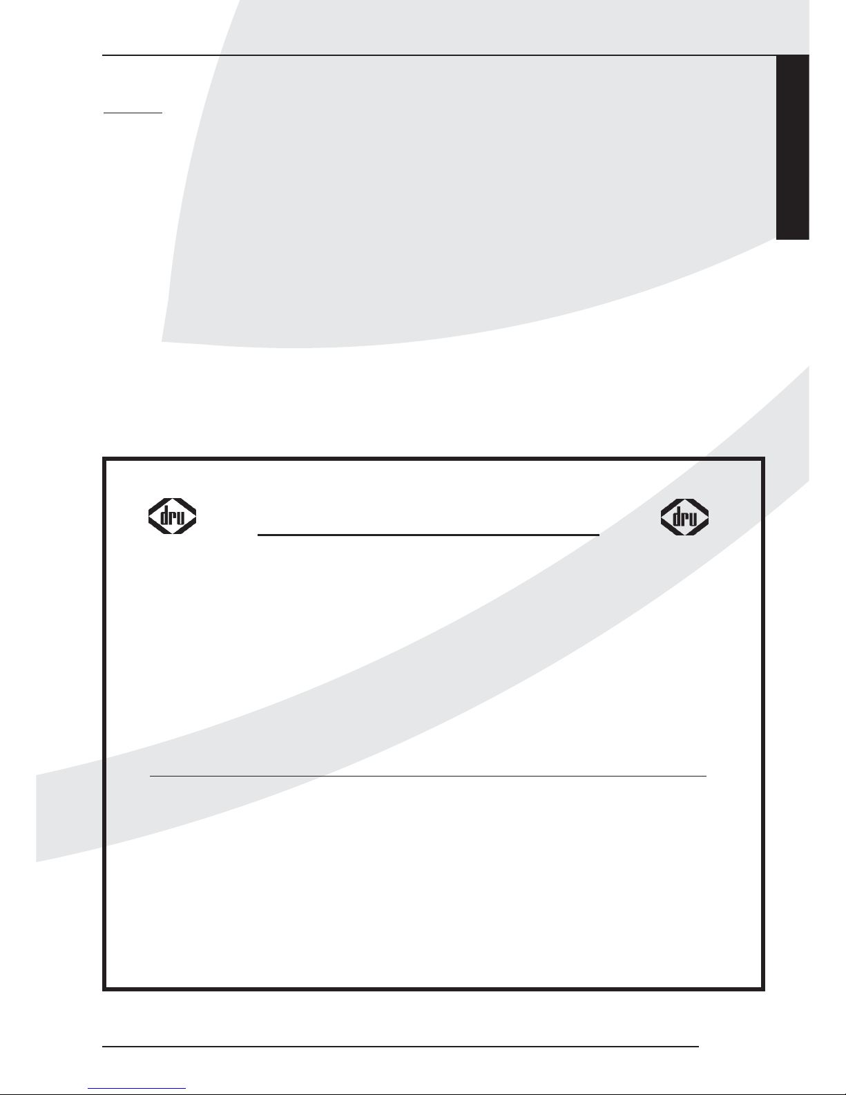
Plaatsen van het toestel
Het toestel is ontworpen om strak in te bouwen in een
nieuw te bouwen boezem van onbrandbaar en
hittebestendig materiaal eventueel met sierschouw. DRU
heeft hiervoor boezems in haar programma.
Men moet bij dit toestel gebruik maken van een
bedieningsluikje (mee geleverd).
Het bedieningsluikje moet binnen een afstand van 1 mtr
links of rechts van de kachel geplaatst worden i.v.m. de
lengte van de leidingen.
Voor afmetingen en montagevoorschriften zie hoofdstuk
bedieningsluikje.
Indien u de boezem bouwt van een materiaal anders dan
steen (b.v.promatect), raden wij u aan glasvezel behang te
gebruiken en geen stucwerk.Voor het geval u toch stucwerk
toepast moet u er op letten dat er niet over de flensen
gestuct wordt.
Er kunnen hierdoor scheuren ontstaan door de warmte van
het toestel.
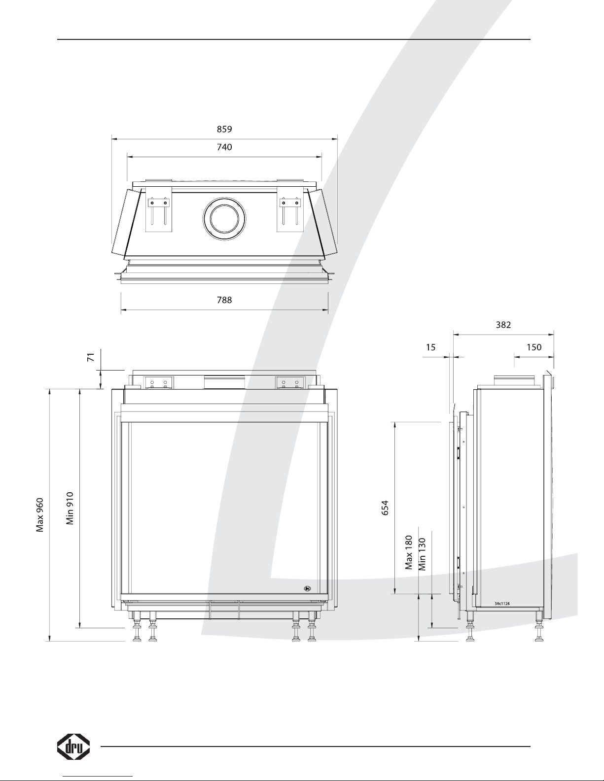
Let op dat er voldoende ruimte is voor de diepte van het
Toestel (400mm). Het toestel mag niet strak tegen de
achterwand worden gemonteerd.
De inbouwhoogte is afhankelijk van de instelling van de
stelvoeten.
Plaats vervolgens het toestel op de gewenste plaats.
Houd in de boezem enige ruimte rondom het toestel
zodat de warmte weg kan.Voor een goede warmte afvoer,
dient de boezem boven voldoende ontlucht te worden.
De gezamenlijke doorlaat moet minimaal 200 cm
2
zijn.
Wij raden u aan de ontluchting aan weerszijde uit te voeren.
DRU heeft hiervoor design ontluchters in haar programma.
Haal de doos met houtblokken en de tas met toebehoren
INSTALLATIEVOORSCHRIFT
2
Page 9
Nederlands
Passeo
INSTALLATIEVOORSCHRIFT
3
38c-1089
min
400mm
n.t.b.
792mm
n.t.b.
n.t.b. 658mm
max
100mm
Totale ontluchting 200cm
2
min 900mm
fig. 1
Maximale stuc lijn Maximale stuc lijn
Haard
Page 10

uit de verbrandingskamer door het glasraam te verwijderen.
Verwijder de acht parkers (fig. 8d) met de bij geleverde
sleutel (fig. 9a).
Pak de handgreep (fig. 9b) en til het glasraam omhoog.
Lift het glasraam uit de rand door de bovenzijde ± 1,5 cm
naar boven te halen en vervolgens ± 1,5 cm naar voren te
halen (fig. 9c).
Draai vervolgens het glasraamkader aan de onderzijde uit
de kachel (fig. 9d).
Het monteren gaat in omgekeerde volgorde. Het toestel is
voorzien van beugels voor wandmontage. Deze dienen ook
gebruikt te worden. Sluit het toestel aan.
Let op: Om een goede ontsteking te waarborgen moet de
ontstekingskabel zoveel mogelijk vrij liggen van de metalen
delen van het toestel. Draai deze dus niet om de gas-,
waakvlam-, of thermokoppelleiding.
Bedieningsluikje (fig. 2C)
Voor het bedieningsluikje moet u een gat maken van 285
mm x 194 mm (h x b).
Plaats het binnenframe (1). Deze kunt u mee metselen
indien u een boezem van steen gebruikt. Indien u een
ander materiaal gebruikt kunt u het binnenframe vastkitten
of met vier verzonken schroefjes vastzetten.
Af fabriek is het gasregel blok onder het toestel
gemonteerd.
In de praktijk kan het gasregelblok niet onder het toestel
blijven zitten en dient los genomen te worden.
Ga hierbij als volgt te werk.
Maak de flexibele gasleiding (sleutel 17) ,aluminium
waakvlamleiding (sleutel 10) en het thermokoppel (sleutel
10) los en wikkel de leidingen af, zorg dat er geen knikken
ontstaan.
Verwijder vervolgens het gasregelblok.
Leid de leidingen naar de gewenste positie, let op dat er
geen vuil in de leidingen komt.
Monteer het gasregelblok aan de beugels (2) van het
binnen frame.
Sluit de leidingen aan op de achterzijde van het
gasregelblok.
Let er op dat u de flexibele slang en de aluminium leiding
gasdicht aandraait.
Het thermokoppel moet men eerst handvast aandraaien
en vervolgens 1 kwart slag met de sleutel.
Plaats de ontvanger van de afstandsbediening in het bakje
(3). Zorg ervoor dat de “LED” naar voren wijst.
Maak het buitenframe met deurtje (4) vast aan het
binnenframe met behulp van de twee parkers (5).
U kunt het buitenframe zo plaatsen afhankelijk of u het
deurtje links of rechts draaiend wilt hebben.
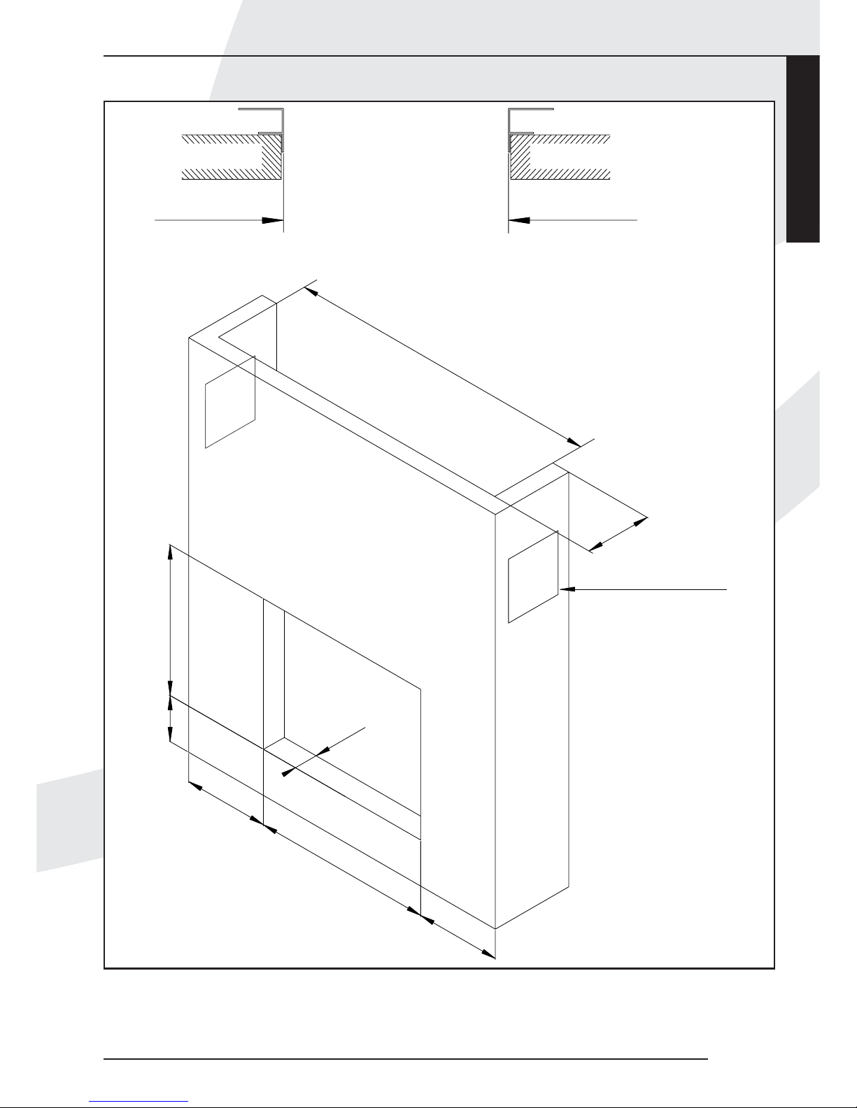
Aansluitmogelijkheden (fig. 4)
De doorvoer naar buiten kan zowel door de gevel als
door het dakvlak plaatsvinden, het aansluiten van de aanen afvoerpijpen dient aan onderstaande voorwaarden te
voldoen:
• altijd eerst 1 meter pijp verticaal plaatsen, behalve fig. 4,
voorbeeld 4.
• de horizontale pijplengte mag nooit langer zijn dan 3
meter en een muurdoorvoer.
• de maximale pijplengte is 12 meter.
Reken voor een 90° bocht 2 meter en voor een 45° bocht
1 meter. De lengte van de gevel- of dakdoorvoer hoeft niet
te worden meegerekend.
De maximale totale lengte is de som van de buislengte
plus de vervangende lengte voor de bochten (zie de 5
voorbeelden in fig. 4).
De dakdoorvoerset, luchtaanvoer / rookgasafvoer, de
concentrische pijp en bochten worden per stuk verpakt en
compleet geleverd met een klemband voorzien van
afdichtring.Tevens is een pan- of plakplaat verkrijgbaar
voor doorvoer door resp. een schuin of een plat dak.
Let op: Dit toestel mag uitsluitend met het door DRU
4
INSTALLATIEVOORSCHRIFT
1
2
3
4
5
38c-1078
fig. 2c
Wandbeugels
Page 11
Nederlands
Passeo
5
geleverde afvoermateriaal ø150/ø100 geïnstalleerd
worden. Dit is samen met het toestel gekeurd en voldoet
hiermee aan alle eisen.Voor afwijkend installatiemateriaal
kan DRU de goede en veilige werking niet garanderen.
Voorbereidingen voor het plaatsen van het
in- en uitlaatsysteem
• Maak een keuze uit de aansluitmogelijkheden volgens
figuur 4.
• Bouw de concentrische pijpen op vanaf het toestel.Als
door bouwkundige omstandigheden eerst een gedeelte
van het concentrische pijpensysteem wordt ingebouwd
let dan speciaal op de juiste montagewijze.
• Het toestel begint met een contradeel. Hierop de eerste
meter pijp plaatsen.
• Houdt een minimale afstand aan van 5 centimeter tussen
de buitenkant van de concentrische pijpen en wand of
plafond.
Geveldoorvoer met concentrische pijpen
Let op dat bij de geveldoorvoer eerst 1 of 0,5 meter pijp
verticaal gemonteerd moet worden. 0,5 meter bij
maximaal 2 meter horizontaal en 1 meter bij maximaal 3
meter horizontaal.
• Bepaal de plaats van het toestel en van de plaats van de
geveldoorvoer.
• Maak op de plaats van de geveldoorvoer een gat van
Ø160 mm. Door brandbaar materiaal Ø 230 mm.
• Sluit nu één of meerdere concentrische pijpen verticaal
aan op de uitmonding van het toestel. Druk deze aan en
breng de klemband(en) aan.
• Plaats hierop de bocht en eventuele horizontale
concentrische pijpen en maak deze ook gasdicht.
• Sluit de geveldoorvoer aan op de bocht of horizontale
pijplengte en zorg dat deze ook gasdicht wordt
afgesloten.
Dakdoorvoer met concentrische pijpen
Een dakdoorvoer kan op elk punt van het dak uitmonden,
eventueel met een versleping naar de nok. De
dakdoorvoer wordt afhankelijk van één van bovenstaande
mogelijkheden geleverd met een plakplaat voor een plat
dak of een universeel verstelbare pan voor een schuin
dak.
• Bepaal de plaats van het toestel en van de plaats van de
dakdoorvoer.
• Maak op de plaats van de dakdoorvoer een gat van Ø160
mm. Door brandbaar materiaal Ø 230 mm.
• Sluit nu de concentrische pijpen verticaal aan op de
uitmonding van het toestel. Druk deze aan en breng de
klemband aan.
• Bepaal de lengte van de benodigde pijpen en zorg ervoor
dat de plakplaat of de universele pan goed aansluit op het
dak.
• Zaag de buitenpijp af op de juiste lengte.
• Sluit de dakdoorvoer aan op de concentrische pijpen.
Let op: u kunt ook eerst de concentrische pijpen
aanbrengen alvorens het toestel te plaatsen. U
dient dan de aansluiting op de uitmonding van
het toestel te maken met een inkortbare pijp.
INSTALLATIEVOORSCHRIFT
5m
4m
12
0,5m
1m
1m
max 2m
2m
1m
max 3m
1m
2x45˚
2x90˚
1x90˚
L=2+0,5+(2)=4,5
L=1+1+4+(2x2)=10
(H totaal= 5m)
L=1+2+5+(2x1)=10
4
1x90˚
L=4+1+(2)=7
38c-744b
fig. 4
1
2
3
4
5
Page 12
6
INSTALLATIEVOORSCHRIFT
Bestaande schoorsteen
Het is ook mogelijk om het toestel op een bestaande
schoorsteen aan te sluiten. Hiervoor wordt door DRU een
speciale schoorsteen aansluitset geleverd. Daarin vindt u
ook een installatievoorschrift voor deze aansluitset.
Bij aansluiting op een bestaande schoorsteen moeten
gelden de volgende punten:
• De schoorsteen moet minimaal Ø150mm zijn.
• De totale lengte mag niet meer zijn dan 12 m en niet
meer dan 3 m horizontaal.
• De schoorsteen dient voor de installatie goed gereinigd te
worden.
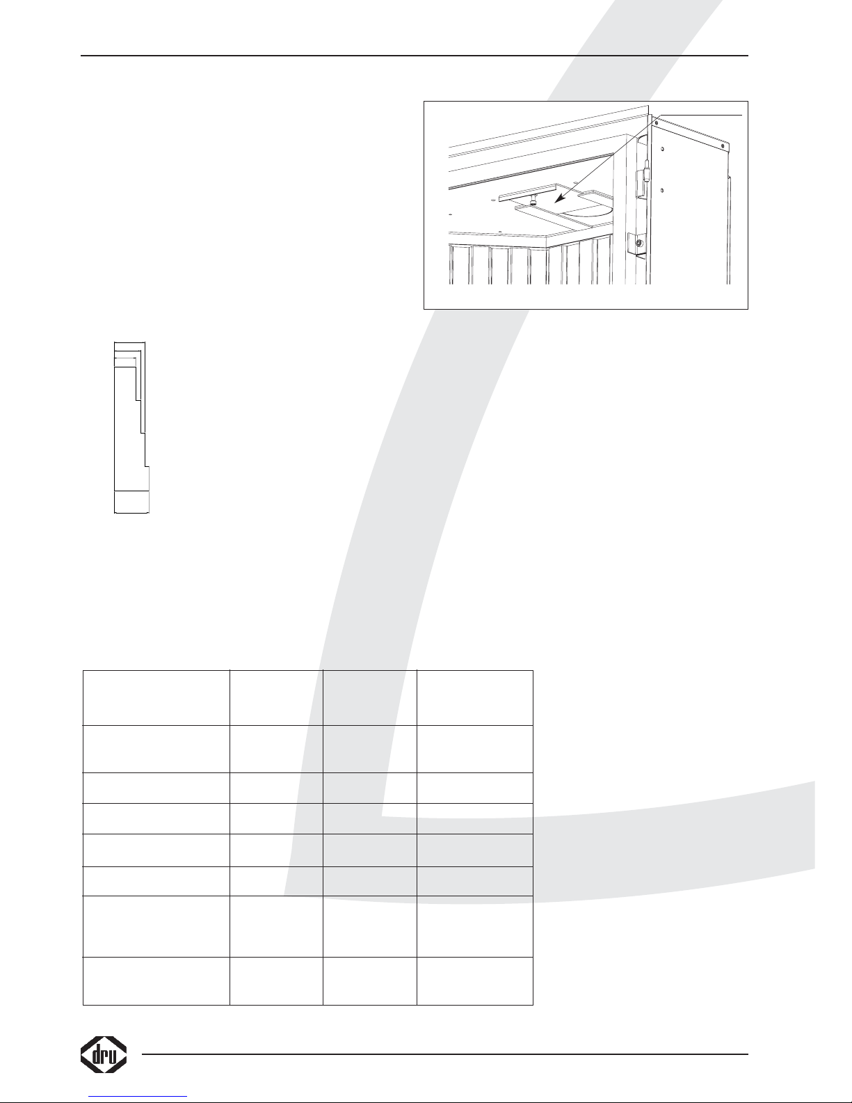
Instellingen restrictieschuif en
luchtinlaatgeleider
Om een goede werking van
het toestel te waarborgen
dient men enkele handelingen
te verrichten zodat het toestel
optimaal wordt afgesteld op het
klantspecifieke pijpensysteem.
Restrictieschuif instellen.
De restrictieschuif wordt los meegeleverd en moet in het
toestel worden geplaatst zoals aangegeven in fig.6.
Met behulp van de bijgeleverde afstelmal (fig. 5) kan de
schuif op de juiste maat afgesteld worden.Na het afstellen
kan de restrictieschuif vastgezet worden met de inbusbout.
Het afstellen moet gebeuren volgens de gegevens in de
tabel.
In een aantal gevallen dient u de luchtinlaat geleider te
verwijderen (zie tabel).
Ga hier bij als volgt te werk (fig. 7).
Pak strip 1 en de vermiculiet bakken (2+3) uit het toestel.
Verwijder de luchtinlaat geleiders en draai de parkers weer
terug op hun plaats.
Plaats de bakken vermiculiet (2+3) en de strip (1) weer
terug in het toestel.
Let op dat de maximale horizontale lengte niet
wordt overschreden.
In figuur 4 is geïllustreerd hoe de totale lengten moeten
worden berekend.
Aansluiting van de gastoevoer
Gebruik in de toevoerleiding een
gekeurde aansluitkraan met koppeling
(voor België moet deze B.G.V.
gekeurd zijn).Verder geldt:
• Ontlucht de toevoerleiding voordat
het toestel wordt vastgekoppeld.
• De bedieningskraan mag niet
verdraaid worden bij het aansluiten
aan de gastoevoerleiding.
• Vermijd spanningen op de
bedieningskraan en leidingen.
• Controleer de aansluitingen op
gasdichtheid.
38c-1083
37±0.5
42±0.5
26±0.5
32±0.5
fig. 5
38C-972
fig. 6
Restrictieschuif
Luchtinlaat Restrictie Afstand
geleider schuif restrictieschuif
8 t/m 12 mtr
verticaal + dakdoorvoer
JA JA 26 mm
5 t/m 7 mtr
verticaal + dakdoorvoer
JA JA 32 mm
3 t/m 4 mtr
verticaal + dakdoorvoer
JA JA 37 mm
1 t/m 2 mtr
verticaal + dakdoorvoer
JA JA 42 mm
1 mtr verticaal +
muurdoorvoer
JA NEE OPEN
1 mtr verticaal +
1 t/m 3 mtr
NEE NEE OPEN
horizontaal +
muurdoorvoer
0.5 mtr verticaal +
2 mtr horizontaal + NEE NEE OPEN
muurdoorvoer
G20/G25
Page 13
Nederlands
INSTALLATIEVOORSCHRIFT
Passeo
7
Luchtinlaat geleider
38c-1084
1
2
3
fig. 7
fig. 8a
fig. 8b
fig. 8c fig. 8d
Remplaat
Page 14
INSTALLATIEVOORSCHRIFT
8
fig. 10
fig. 9a fig. 9b
fig. 9c fig. 9d
Page 15
Nederlands
INSTALLATIEVOORSCHRIFT
Passeo
9
fig. 11
fig. 12
Page 16
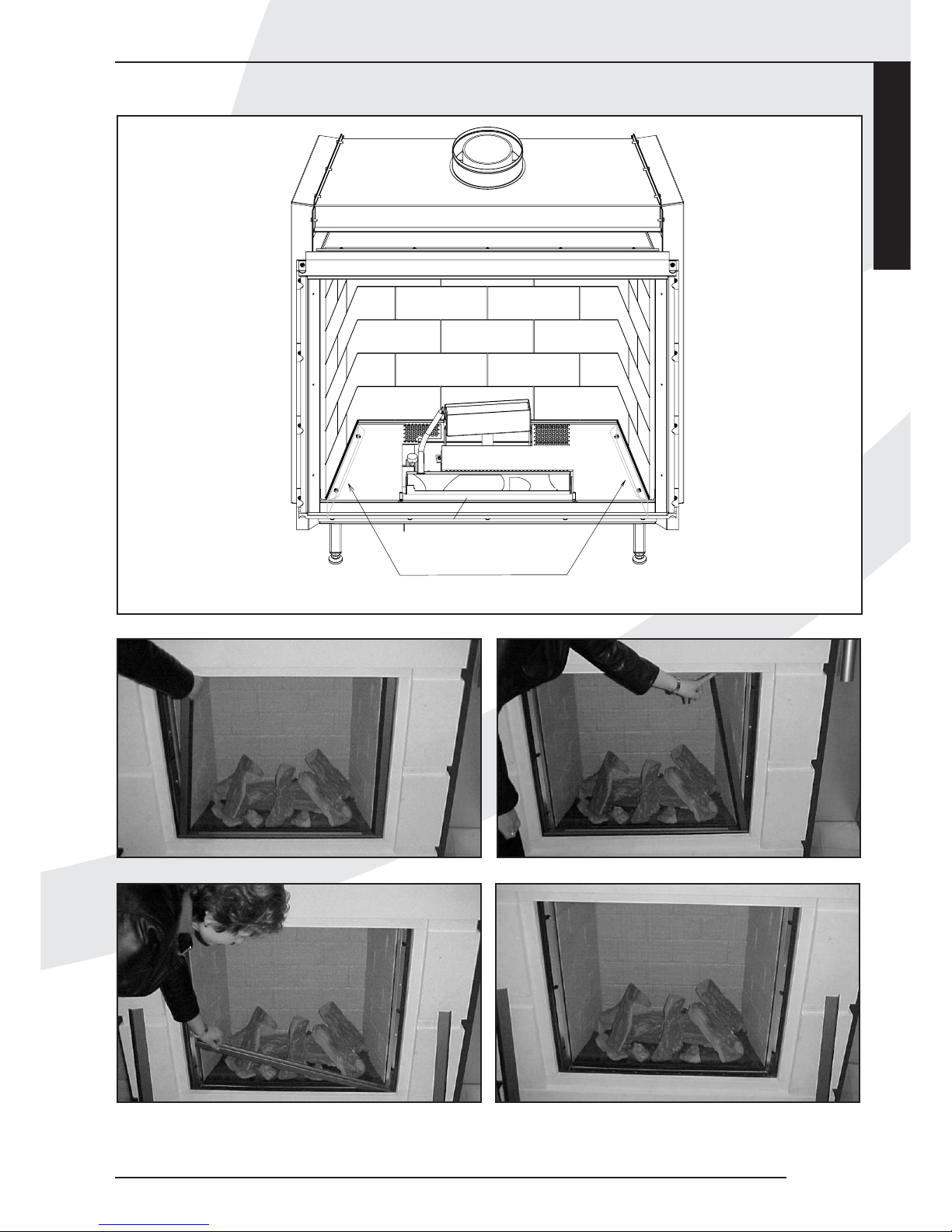
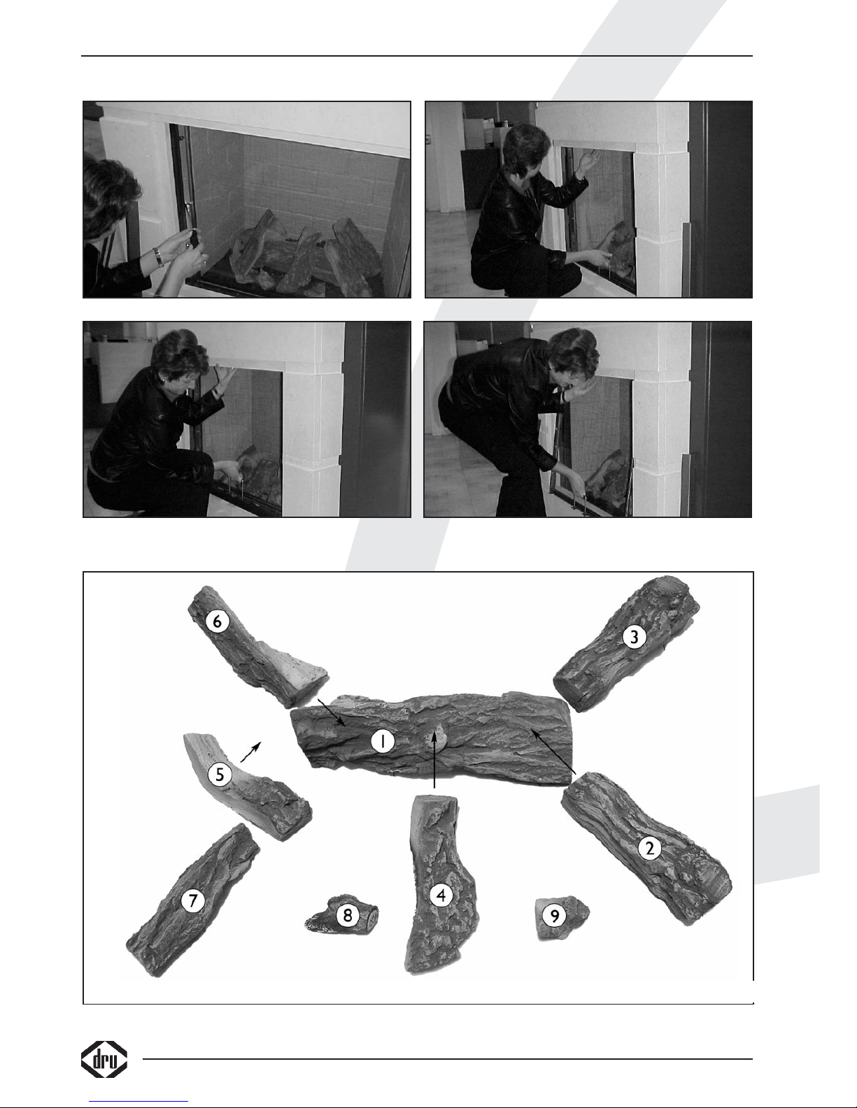
Plaatsen van de houtblokken
Verdeel het vermiculiet gelijkmatig over de voorste en
over de achterste brander. Let op dat er niet te veel
vermiculiet op de ontsteekplaatsen van de voorste en de
achterste brander ligt.
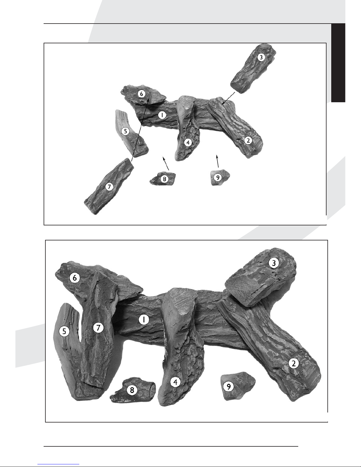
Overzicht foto met losse stammen(fig. 10) / Groepsfoto
met stammen in positie gelegd (fig. 12).
Stam 1:Tegen de nokken op de achterste brander
Stam 2: Schuin over stam 1 met de noestzijde naar
beneden
Stam 3: Met de noestzijde in de hoek op stam 2
Stam 4: In het midden van de kachel tegen de aanslag op
stam 1,voorzijde tegen de tandjes op de brander
Stam 5: Schuin naar achter en op de steun van de voorste
brander
Stam 6: In de linker hoek op stam 1 (op de achter zijde
van stam 1 bevind zich een nok)
Stam 7: Boven op stam 5 en schuin omhoog naar stam 6
Stam 8: Schuin over stam 5 (mag niet op het brander
oppervlak liggen)
Stam 9: Met de knobbel in de brander en de voorzijde op
de tandjes van de voorste brander
Verdeel de chips rondom de blokken.
De chips mag aan de voorzijde op tandjes van de brander
worden gelegd, (schuin omhoog).
Niet geheel dichtleggen er moet lucht langs kunnen.
De blokken mogen niet op een andere manier neergelegd
worden, omdat dan roetvorming kan ontstaan, ook mogen
de blokken niet tegen de waakvlam brander aan liggen.
Gebruik geen andere materialen dan die meegeleverd zijn.
De meegeleverde materialen zijn onbrandbaar en speciaal
voor dit toestel gemaakt.
Demonteren / monteren glasraamkader
Verwijder de sierpanelen , worden los geleverd,(fig. 8a t/m c).
Verwijder de acht parkers (fig. 8d) met de bij geleverde
sleutel (fig. 9a).
Pak de handgreep (fig. 9b) en til het glasraam omhoog.
Lift het glasraam uit de haken door de bovenzijde ± 1,5
cm naar boven te halen en vervolgens ± 1,5 cm naar voren
te halen (fig. 9c).
Draai vervolgens het glasraamkader aan de onderzijde uit
de kachel (fig. 9d).
Het monteren gaat in omgekeerde volgorde.
Draadloze bediening
De haard wordt standaard geleverd met een draadloze
bediening. Het toestel is voorzien van een traploos
regelbaar gasregelblok. De elektrische voeding wordt
verzorgd door batterijen. De levensduur van de batterijen
is ongeveer één jaar. De draadloze bediening werkt alleen
wanneer de waakvlambrander is ontstoken.
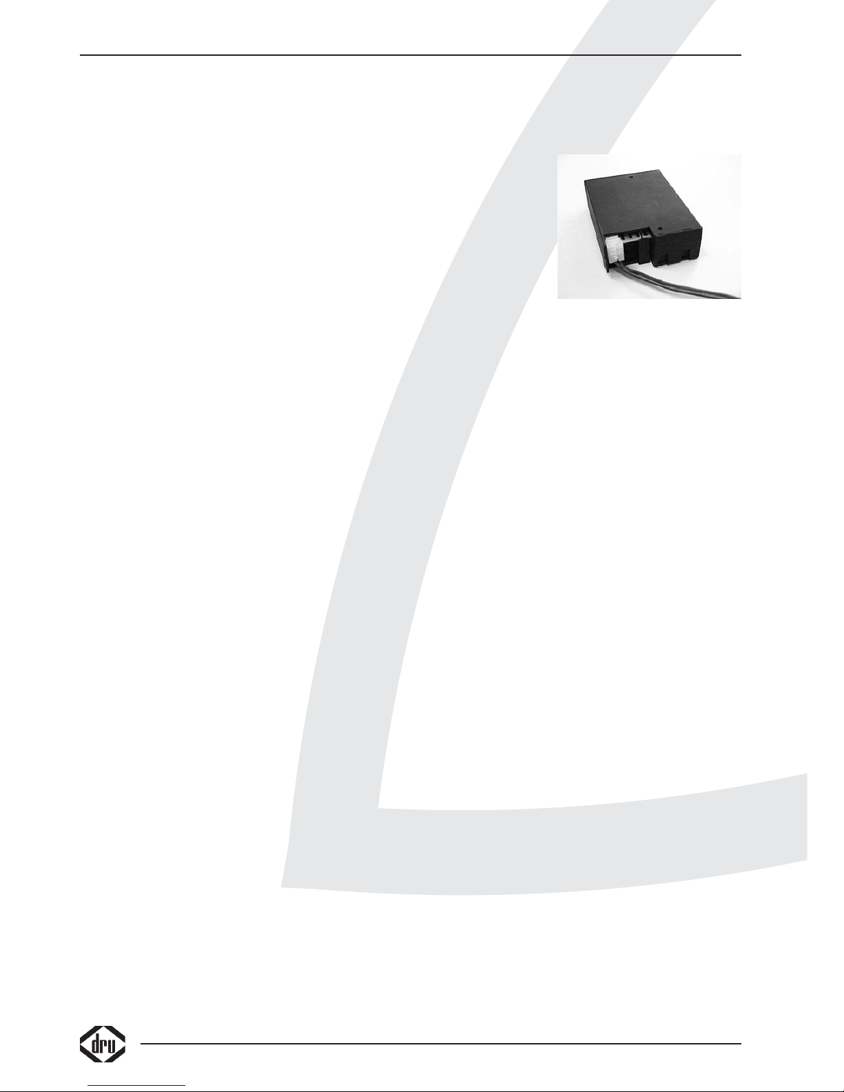
Aansluiten van de ontvanger
De draadloze bediening bestaat uit een ontvanger en een
afstandsbediening. Deze zijn samen verpakt in een doos.
De ontvanger moet
worden
aangesloten in het
toestel voordat de
batterijen worden
gemonteerd.
Ga hiervoor als
volgt te werk:
• Neem de
ontvanger uit de
verpakking.
• Schuif de witte stekker van het aansluitsnoer achterop de
printplaat van de ontvanger (fig. 10).
• Sluit de snoeren aan op de connectoren van het
gasregelblok. De stekkers hebben verschillende maten en
corresponderen met de connectoren op het gasregelblok.
• Neem de deksel los.
• Plaats de 4 penlite batterijen (type AA). Let op de juiste
poolrichtingen.
• Plaats de deksel terug.
• Plaats de ontvanger van de afstandsbediening in het
bedieningsluikje. Zorg ervoor dat de rode “LED” naar
voren wijst.
Vervangen van de batterijen in de ontvanger
• Open de deur van het bedieningsluikje.
• Neem de ontvanger en open de deksel.
Achter deze deksel bevindt zich de batterijhouder.
• Verwijder de oude batterijen en plaats de nieuwe, let
daarbij op de + en – aansluiting van de batterijen en de
houder; deze moeten overeenkomen.
Plaatsen of vervangen van de batterijen in de
afstandsbediening
• Verwijder de deksel aan de onderzijde van de
afstandsbediening.
• Sluit de blokbatterij (type 6LR61) aan op de clip.
• Plaats de batterij in de houder.
• Sluit de deksel.
• In het display staat de temperatuur aangegeven in
Fahrenheit, door beide knoppen enkele seconden
ingedrukt te houden, verandert dit in Celsius.
Let op: oude batterijen mogen niet bij het huisvuil maar
moeten bij het Klein Chemisch Afval.
Dru adviseert Duracell batterijen voor een optimale
werking en levensduur van haar toestel.
GEBRUIKERSHANDLEIDING
10
fig. 10
Page 17
GEBRUIKERSHANDLEIDING
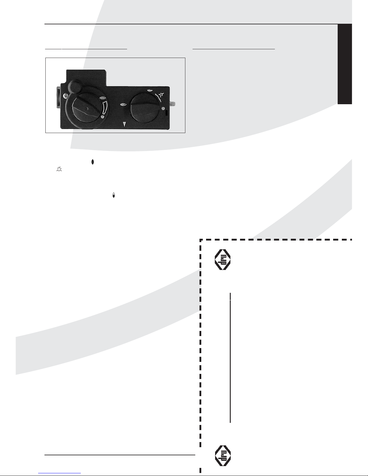
Aansteken
Knop A in drukken en linksom draaien
tot de kleine vlam .
Bij zal het toestel ontsteken. Controleer of de
waakvlam brandt. Indien de waakvlam brandt, knop A nog
ca. 5 sec. geheel ingedrukt houden. Daarnaknop A loslaten
en controleren of de waakvlam blijft branden. Draai nu
knop A naar de grote vlam . Hierdoor zal de hoofdklep
van het regelblok opengaan.Afhankelijk van de stand van
de regelknop B zal de hoofdbrander door de waakvlam
ontstoken worden en zullen hogere of lagere vlammen te
zien zijn.
Afstandsbediening
Met de afstandsbediening kan de vlamhoogte worden
geregeld. Knop B op het gasregelblok zal hierdoor draaien.
Door op de onderste knop van de afstandsbediening te
drukken zal de vlam kleiner worden, drukt u op de
bovenste knop dan zal de vlam hoger worden. Indien knop
B met de hand bediend wordt zal hetzelfde resultaat
worden bereikt. Het verdraaien van knop B moet met
enige kracht gebeuren, het klinken van tikken is hierbij
volstrekt normaal.
Waakvlamstand
Wanneer de kachel niet gebruikt wordt maar wel de
waakvlam moet branden kan knop A naar de kleine vlam
worden gedraaid. Hierdoor wordt de gastoevoer naar de
hoofdbrander afgesloten
Uitschakelen
Draai knop A rechtsom naar de "0" stand. De gastoevoer
naar de hoofd- en de waakvlambrander is dan gesloten.
Belangrijk
Een ingebouwde veiligheidsvergrendeling treedt in werking
wanneer het toestel op ,"UIT" (gesloten stand) wordt
gezet.Wacht daarom 5 minuten alvorens het toestel
opnieuw te ontsteken. Probeer binnen deze tijd niet de
aansteekknop in te drukken, daar deze door de veiligheids
vergrendeling geblokkeerd is. Forceer de knop niet, omdat
het mechanisme dan kan worden beschadigd.
ALGEMENE OPMERKINGEN
Onderhoud en reiniging
Uw toestel dient eenmaal per jaar door een gekwalificeerd
bedrijf te worden gecontroleerd, en waar nodig, hersteld
of gereinigd. De controle en het onderhoud dient in ieder
geval een goede en veilige werking van het toestel te
omvatten. U kunt hiervoor gebruik maken van uw
gasinstallateur of een gespecialiseerd onderhoudsbedrijf.
Het verdient aanbeveling om vóór en tijdens het
stookseizoen het toestel enkele malen stofvrij te maken.
Op de binnenkant van het glasraam kan zich na verloop
van tijd aanslag vormen U kunt deze verwijderen met een
vochtige doek of met een nietkrassend reinigingsmiddel
(zoals koperpoets). Doe dit zodra aanslag verschijnt, zodat
deze niet kan inbranden en reinigen onmogelijk wordt. Bij
het reinigen van de mantel geen bijtende of schurende
middelen gebruiken. Lakbeschadigingen, bijvoorbeeld door
het plaatsen van voorwerpen op of tegen de mantel, vallen
buiten de garantie.
Let op: Bij het vervangen van het thermo-element moet
de wartel in het gasregelblok handvast gedraaid worden,
waarna deze met een steeksleutel een kwartslag
aangedraaid moet worden.
Nederlands
ALGEMENE OPMERKINGEN
REGISTRATIEKAART
DRU Verwarming kan alleen garantie verlenen indien deze registratiekaart volledig en duidelijk
in blokletters en binnen 5 dagen opgestuurd is aan DRU Verwarming B.V.
Type: . . . . . . . . . . . . . . . . . . . . . . . . . . . . . . . . . . . . . . Aankoopdatum: . . . . . . . . . . . . . . . . . . . . . . . . . . . . . . . . .
Kleur: . . . . . . . . . . . . . . . . . . . . . . . . . . . . . . . . . . . . . Serienummer (op typeplaat): . . . . . . . . . . . . . . . . . . . . . .
Koper: Detaillist/installateur:
Naam . . . . . . . . . . . . . . . . . . . . . . . . . . . . . . . . . . . . . Naam . . . . . . . . . . . . . . . . . . . . . . . . . . . . . . . . . . . . . . . . .
Adres . . . . . . . . . . . . . . . . . . . . . . . . . . . . . . . . . . . . . Adres . . . . . . . . . . . . . . . . . . . . . . . . . . . . . . . . . . . . . . . . .
Postcode . . . . . . . . . . . . . . . . . . . . . . . . . . . . . . . . . . . Postcode . . . . . . . . . . . . . . . . . . . . . . . . . . . . . . . . . . . . . .
Plaats . . . . . . . . . . . . . . . . . . . . . . . . . . . . . . . . . . . . . . Plaats . . . . . . . . . . . . . . . . . . . . . . . . . . . . . . . . . . . . . . . . .
Telefoon . . . . . . . . . . . . . . . . . . . . . . . . . . . . . . . . . . . Telefoon . . . . . . . . . . . . . . . . . . . . . . . . . . . . . . . . . . . . . . .
Hartelijk dank voor uw medewerking.
fig. 11
A
B
Page 18
Verkleuring van wanden en plafonds
Bruinverkleuring is een vervelend probleem en is moeilijk
op te lossen. Bruinverkleuring kan worden veroorzaakt
door onder andere stofverbranding veroorzaakt door te
weinig ventilatie, door het roken van sigaretten of het
branden van kaarsen.
Deze problemen kunnen worden voorkomen door:
Het vertrek waar het toestel zich bevind goed te
ventileren. Een goede richtlijn hiervoor is (vlg. het
Nederlands Bouwbesluit):
Bij nieuwbouw : 3.24 m
3
/ uur per m
2
vloeroppervlak van een vertrek.
Bij bestaande bouw : 25.20 m3/ uur voor een vertrek.
Maak zo weinig mogelijk gebruik van kaarsen en
olielampjes en houd het verbrandingslontje zo kort
mogelijk. Deze "sfeerbrengers" zorgen voor aanzienlijke
hoeveelheden vervuilde en ongezonde roetdeeltjes in uw
woning. Rook van sigaretten en sigaren bevat o.a.
teerstoffen die bij verhitting eveneens op koudere en
vochtige muren zullen neerslaan. Bij een nieuw gemetselde
schouw of na een verbouwing wordt aanbevolen minimaal
6 weken te wachten voordat men gaat stoken, het
bouwvocht moet namelijk geheel verdwenen zijn uit
wanden, vloer en plafond.
Eerste maal stoken
Tijdens de eerste maal stoken kan er een onaangename
geur ontstaan, die wordt veroorzaakt door het uitdampen
van de lak. Dit verdwijnt na enkele uren. Daarom raden wij
u aan het toestel de eerste maal op de hoogste stand te
stoken terwijl u tevens het vertrek waarin de kachel staat
goed ventileert.
Extra bescherming
Indien het toestel in een vertrek geïnstalleerd wordt waar
jonge kinderen of hulpbehoevende mensen zonder
toezicht verblijven, adviseren wij het toestel af te
schermen.
Afdanken
Indien u het toestel vervangt of verwijdert, moet u het
toestel via de reguliere weg afvoeren.Voordat tot
demontage wordt overgegaan eerst de aansluitkraan met
koppeling dichtdraaien. De koppeling tussen aansluitkraan
en toestel losdraaien. Het gehele toestel kan nu worden
gedemonteerd en afgevoerd.
Garantie
De REGISTRATIEKAART gelieve binnen 5 dagen na
aankoop in te vullen en op te sturen in een envelop
zonder postzegel naar het onderstaande adres.
DRU VERWARMING B.V.
ANTWOORDNUMMER 4551
6920 ZX DUIVEN
Het GARANTIEBEWIJS (blz. 1) kunt u zelf behouden.
De garantie gaat in op het ogenblik, dat de volledig
ingevulde registratiekaart door DRU Verwarming is
ontvangen.
Voor België de kaart invullen op pagina
47 en 48.
ALGEMENE OPMERKINGEN
VERSTUREN IN EEN
ENVELOP
DRU VERWARMING B.V.
ANTWOORDNUMMER 4551
6920 ZX DUIVEN
Page 19

CONTENTS
Important . . . . . . . . . . . . . . . . . . . . . . . . . . . . . . . . . .14
Foreword . . . . . . . . . . . . . . . . . . . . . . . . . . . . . . . . . .14
Unpacking . . . . . . . . . . . . . . . . . . . . . . . . . . . . . . . . . .14
Connection . . . . . . . . . . . . . . . . . . . . . . . . . . . . . . . .14
Instructions for installation . . . . . . . . . . . . . . . . . . . .14
Type of gas . . . . . . . . . . . . . . . . . . . . . . . . . . . . . . . . .14
Important . . . . . . . . . . . . . . . . . . . . . . . . . . . . . . . . . .14
Positioning the appliance . . . . . . . . . . . . . . . . . . . . . .14
Service flap . . . . . . . . . . . . . . . . . . . . . . . . . . . . . . . . .16
Possible connections . . . . . . . . . . . . . . . . . . . . . . . . .16
Preparations for the installation of
the combined inlet-outlet system . . . . . . . . . . . . . . .17
Wall duct with concentric pipes . . . . . . . . . . . . . . . .17
Roof duct with concentric pipes . . . . . . . . . . . . . . . .17
Fitting the fire to an existing chimney . . . . . . . . . . .18
Baffle . . . . . . . . . . . . . . . . . . . . . . . . . . . . . . . . . . . . . .18
Connecting the Gas Supply . . . . . . . . . . . . . . . . . . . .18
Positioning the logs . . . . . . . . . . . . . . . . . . . . . . . . . .22
Dismantling / Fitting glass window frame . . . . . . . . .22
Remote control . . . . . . . . . . . . . . . . . . . . . . . . . . . . .22
Connecting the Receiver . . . . . . . . . . . . . . . . . . . . . .22
Replacing the batteries in the receiver . . . . . . . . . . .22
Inserting or replacing the batteries
in the remote control . . . . . . . . . . . . . . . . . . . . . . . .22
Operating Instructions . . . . . . . . . . . . . . . . . . . . . . .23
Lighting . . . . . . . . . . . . . . . . . . . . . . . . . . . . . . . . . . . .23
Remote Control . . . . . . . . . . . . . . . . . . . . . . . . . . . .23
Pilot light setting . . . . . . . . . . . . . . . . . . . . . . . . . . . .23
Switching off . . . . . . . . . . . . . . . . . . . . . . . . . . . . . . . .23
Important . . . . . . . . . . . . . . . . . . . . . . . . . . . . . . . . . .23
General notes . . . . . . . . . . . . . . . . . . . . . . . . . . . . . .23
Gas safety regulations (for installation & use), 1998 23
Cleaning and Maintenance . . . . . . . . . . . . . . . . . . . .23
Discoloration of walls and ceiling . . . . . . . . . . . . . . .24
Lighting the heater for the first time . . . . . . . . . . . .24
Extra protection . . . . . . . . . . . . . . . . . . . . . . . . . . . .24
Disposal . . . . . . . . . . . . . . . . . . . . . . . . . . . . . . . . . . .24
Guarantee . . . . . . . . . . . . . . . . . . . . . . . . . . . . . . . . .24
Technical specifications . . . . . . . . . . . . . . . . . . . . . . .51
English
Passeo
CONTENTS
13
Conditions of warranty
• This appliance has been manufactured and tested by DRU verwarming BV of The Netherlands with utmost care.
• Subject to the conditions set out on this card DRU guarantees the proper operation of this vented room heater to the original purchaser for a period of
one year after date of purchase.
• Subject to the conditions set out on this card, the cast iron combustion chamber of your DRU vented room heater carries a full guarantee to the original
purchaser for a period of ten years after date of purchase.
• The guarantee does not cover the normal wear and tear, damage due to incorrect treatment, changes of the equipment or unauthorised installations and
repairs. No liability is assumed by DRU for removal or (re)installation labor costs.
• Under no circumstances shall DRU be liable for incidental,consequential, special or contingent damages or expenses arising directly or indirectly from any
defect in the product or any component or from the use thereof.The remedies set forth herein are the exclusive remedies available to the user and are in
lieu of all other remedies. Subject to specific state laws some of the above limitations or exclusions may not apply to you.
DRU Verwarming B.V.
WARRANTY CARD
Please complete this card and keep it with the invoice to verify purchase date
and to establish the warranty period*.
Model: . . . . . . . . . . . . . . . . . . . . . . . . . . . . . . . . . . Date: . . . . . . . . . . . . . . . . . . . . . . . . . . . . . . . . . . . .
Colour: . . . . . . . . . . . . . . . . . . . . . . . . . . . . . . . . . Serial No.: . . . . . . . . . . . . . . . . . . . . . . . . . . . . . . . .
Type of Gas: Natural Gas L.P.G. (please check)
Customer: Dealer/Installer
Name . . . . . . . . . . . . . . . . . . . . . . . . . . . . . . . . . . Name . . . . . . . . . . . . . . . . . . . . . . . . . . . . . . . . . . .
Address . . . . . . . . . . . . . . . . . . . . . . . . . . . . . . . . . Address . . . . . . . . . . . . . . . . . . . . . . . . . . . . . . . . . .
City . . . . . . . . . . . . . . . . . . . . . . . . . . . . . . . . . . . City . . . . . . . . . . . . . . . . . . . . . . . . . . . . . . . . . . . . .
State . . . . . . . . . . . . . . . . . . . . . . . . . .ZIP . . . . . . State . . . . . . . . . . . . . . . . . . . . . . . . . .ZIP . . . . . . .
Province . . . . . . . . . . . . . . . . . . . . . . .P.C. . . . . . . Province . . . . . . . . . . . . . . . . . . . . . . .P.C. . . . . . .
Telephone ( . . . . . . . . . .) . . . . . . . . . . . . . . . . . . . .
*FOR SERVICE UNDER THIS WARRANTY CONTACT YOUR DEALER/INSTALLER.
DRU warrants the proper functioning of this vented roomheater if installed by a qualified installer and if used in
strict accordance with the manufacturers operating instructions
Page 20

Important
• The appliance should be fitted with a service flap
(provided), please read the instructions on page 16.
• The chimney breast should be ventilated, e.g. with the
DRU vents available (2x) or alternatively with openings or
grilles with a minimum total free vent area of 200 cm2.
• If the fire is to be built in flush with the wall, make sure
the edges of the chimney breast are neatly finished and
not plastered over as they will remain visible.
• Be careful not to damage the chimney breast or fireplace
when fitting or removing the glass pane.
• The appliance must not be fitted with an insulation blanket
or in any other way wrapped or covered.
• Always clean the glass pane before using the fire to avoid
marks such as fingerprints burning in.
• This appliance may only be installed using the Ø150/Ø100
flue material supplied by DRU.
• The space under the heater must be kept free to ensure
the by-pass valve will function correctly if necessary.
• NB:
To ensure the ignition works properly, the ignition
wire must come into as little contact as possible with the
metal parts of the heater and should therefore not be
wound round the gas or pilot-light pipes or the thermocouple.
• The pilot burner and the overflow burner must always be kept
clear of obstruction so that the flames remains unblocked at
all times.
• It is vitally important that you adhere to the correct
positioning of the logs as specified. Failure to do this may
result in an unsafe situation.
Foreword
Dear Customer,
We would like to thank you for buying this DRU product.
Our products have been designed and produced to meet the
highest possible quality, performance and safety requirements,
allowing you to enjoy years of problem-free use.
The heater has an enclosed combustion chamber. Its
natural draught draws in the combustion air from outside
through a combined inlet-outlet system.The same natural
draught expels the combustion gasses.
In this booklet you will find instructions for the installation
and use of your new appliance. Please read these
instructions and the manual carefully to familiarize yourself
with the appliance. If you require any further support,
please do not hesitate to contact your supplier.
Unpacking
Once the heater has been unpacked, all packaging should
be disposed of in the regular manner.
Connection
This appliance should be connected by a registered
gasinstaller.
INSTRUCTIONS FOR INSTALLATION
Type of gas
This appliance can only be used and is only suitable for the
country and the type of gas mentioned on the type
identification tag. Please check that the local gas and
pressure correspond with the specifications on the type
identification tag.The type identification tag is a metal
plate.
All regulations regarding gas installation, including any local
regulations, must be observed at all times. The appliance is
to be installed by a registered gasinstaller.
Important
• Keep curtains and any other flammable materials at least
50cm away form the appliance.
• Caution! Touching the heater when hot can cause burns
and blisters!
• The appliance should be installed and maintained by a
registered gasinstaller.
• Do not install any so-called dust filter on or under the
casing.
• Do not hang wet clothes and towels etc. on the heater to
dry.
Positioning the appliance
The appliance has been designed to be built snugly into a
newly built chimney breast of incombustible and heatresistant material, optionally with a decorative mantelpiece.
The DRU range includes several suitable chimney breasts.
For this appliance you will need to use a service flap.
The service flap should be fitted within 1 metre left or right
of the heater, to allow for the length of the wires.
For the dimensions and installation instructions, see the
section on the service flap.
If you build the chimney breast of any material other than
stone (e.g. Promatect), we advise you to use a fibreglass
wallpaper and not plaster.
If you do use plaster make sure the flanges are not
plastered over as they could crack from the heat of the fire.
Allow sufficient space for the depth of the appliance
(400 mm).The appliance must not be mounted too closely
against the back wall.
The built-in height will depend on how high the adjustable
feet are set.
Now move the appliance into the required position.
Allow a little room all round the appliance in the fireplace
so that the heat can escape.
To allow adequate heat removalthe chimney breast should
be well vented.
The total free vent area should be at least 200 cm
2
.
We advise you to fit vents on both sides.
The DRU range includes suitable design vents.
Take the box of logs and the bag of accessories out of the
combustion chamber by removing the glass pane.
Remove the eight self-tapping screws with the spanner
provided (fig. 9a).
Holding the handle (fig. 9b) lift the glass pane.
Lift the glass pane out of its hooks by lifting the top approx
1.5 cm and then tilting it forwards approx. 1.5 cm (fig. 9c).
INSTRUCTIONS FOR INSTALLATION
14
Page 21

English
Passeo
INSTRUCTIONS FOR INSTALLATION
15
38c-1089
min
400mm
n.t.b.
792mm
n.t.b.
n.t.b. 658mm
max
100mm
Totale ontluchting 200cm
2
min 900mm
fig. 1
Max plaster line Max plaster line
Heater
total free vent area of 200 cm
2
Page 22

Twist the window frame at the bottom of the heater in the
direction of the arrows, as shown in fig. 9d.
Reassemble in reverse order. The appliance has brackets for
wall assembly.These must be used. Connect the appliance.
NB: To ensure the ignition works properly, the ignition wire
must come into as little contact as possible with the metal
parts of the heater and should therefore not be wound
round the gas or pilot-light pipes or the thermocouple.
Service flap (fig. 2C).
Make a hole of 285 mm x 194 mm (h x w) for the service
flap.
Fit the inner frame (1). If you are building a brickwork
chimney breast the frame can be built in at the same time.
For a chimney breast of any other material,glue/cement the
inner frame in place or fit it with four countersunk screws
Ex-works, the gas control block is mounted under the
appliance.
The gas control block cannot stay under the appliance
however, and should be removed.
To do this:
Undo the flexible gas pipe (spanner 17), the aluminium pilot
light pipe (spanner 10) and the thermocouple (spanner 10)
and carefully unwind the pipes, making sure there are no
kinks.
Now remove the gas control block.
Lead the pipes to the required position, making sure that no
dirt gets into them.
Mount the gas control block on the brackets (2) on the
inner frame.
Connect the pipes to the back of the gas control block.
Make sure that the flexible hose and the aluminium pipe
connections are gastight.
First screw the thermocouple on by hand, and then tighten
one quarter turn with the spanner.
Place the receiver in the tray (3). Make sure the “LED” is
pointing forwards.
Fit the outer frame with flap (4) to the inner frame using
the two self-tapping screws (5).
The outer frame can be fitted with the flap turning to the
left or the right, as required.
Possible connections (fig. 4)
The external duct can pass through either the wall or the
roof; the connections to both supply and flue pipes should
meet the following requirements:
• The first metre of pipe should always be fitted vertically,
except example 4 in fig. 4.
• The horizontal length of pipe should never be more than
3metres and a wall duct.
• The maximum length of vertical pipe is 12 metres.
Allow 2 metres for a bend of 90° and 1 metre for a 45°
bend.There is no need to allow for the length of the wall
or roof duct.
The maximum total length is the sum of the pipe lengths
plus the equivalent length for the bends (see the 5
examples in fig. 4).
The roof duct set, the supply and flue pipes, the concentric
pipe and bends are packed individually and supplied
together with a clip binding with sealing ring.Tile flashing
or adhesive flashing is also available for use with a duct
through a slanting or flat roof respectively.
NB: This appliance may only be installed using the flue
material ø150/ø100 supplied by DRU.This has been
approved together with the appliance to comply with all
INSTRUCTIONS FOR INSTALLATION
16
1
2
3
4
5
38c-1078
fig. 2c
Brackets for
wall assembly
Page 23

requirements. DRU cannot guarantee that the appliance
will work correctly and safely if alternative installation
material is used.
Preparations for the installation of the
combined inlet-outlet system
• Select the required connection from the options shown
in figure 3.
• Erect the concentric pipes from the heater up. If the
structural situation requires that the first section of the
concentric pipe system be built in, take special note of
the required method of assembly.
• The appliance has a coupling section; fit the first metre of
pipe onto this.
• Allow at least 5 cm between the outside of the
concentric pipes and the wall or ceiling.
Wall duct with concentric pipes
You must consider that for a wall duct, the first 1 or 0.5
metres of pipe must be fitted vertically. 0,5 metre for a
maximum of 2 metres horizontal pipe, and 1 metres for a
maximum of 3 metres of horizontal pipe.
• Determine the position of the appliance and the position
of the wall duct.
• Drill a Ø160 mm hole at the point where the wall duct is
required.Through flammable material Ø 230 mm.
• Now vertically connect one or more concentric pipes to
the heater outlet. Press well and fit the strip(s) of clip
binding.
• Place the bend on top of this, fit any horizontal concentric
pipes required, and make sure the connections are
gastight.
• Connect the wall duct to the bend or the horizontal pipes
and make sure that this connection is also gastight.
Roof duct with concentric pipes
A duct through a roof can open out anywhere on the roof,
with an extension to the ridge if necessary. Depending on
which of the aforementioned options has been chosen, the
roof duct will be supplied with either adhesive flashing for
a flat roof or a universally adjustable tile for a slanted roof.
• Determine the position of the appliance and the position
of the chimney.
• Drill a Ø 160 mm hole at the point where the chimney
is required.Through flammable material Ø 230 mm.
• Now vertically connect the concentric pipes to the
heater outlet. Press well and apply the clip binding.
• Determine the length of the pipes required and ensure
that the adhesive flashing or the universal tile fit properly.
• Saw the outside pipe off at the length required.
• Connect the roof duct to the concentric pipes.
NB: Alternatively, you can fit the concentric pipes before
installing the heater. In that case the connection to the
outlet of the appliance should be made using a length of
pipe that can be shortened later.
English
Passeo
INSTRUCTIONS FOR INSTALLATION
17
5m
4m
12
0,5m
1m
1m
max 2m
2m
1m
max 3m
1m
2x45˚
2x90˚
1x90˚
L=2+0,5+(2)=4,5
L=1+1+4+(2x2)=10
(H totaal= 5m)
L=1+2+5+(2x1)=10
4
1x90˚
L=4+1+(2)=7
38c-744b
fig. 4
1
2
3
4
5
Page 24

Fitting the fire to an existing chimney
The fire can be fitted into an existing chimney providing
that the chimney / flue dimensions are 150 mm or more.
A special flue kit is required, which can be obtained from
Drugasar or a Drugasar agent. Do not use any other type
of flue system for this.
BS 5871 – 1 : 2001
Any chimney previously used for an appliance burning a
fuel other than gas shall be swept thoroughly before
installing any gas appliance.
Appliances shall be connected only to the types and sizes
of flue system as specified.
For any other information about this flue system please
contact Drugasar or Drugasar approved agent.
Baffle
To ensure that the appliance
satisfactorily,
it will need to be adjusted
according to the
customer-specific pipe system.
Adjusting the baffle.
The baffle plate is supplied separately and should be fitted
into the heater as indicated in fig. 6.
Use the adjustment jig provided (fig. 5) to adjust the baffle
to the right size. Once it has been adjusted, fix the damper
in place with the socket-head screw.
See the table for adjustment specifications.
In some cases the air inlet baffle should be removed
(tabel).
To do this: (fig. 7).
Take strip (1) and the vermiculite trays (2+3) out of the
appliance.
Remove the air inlet baffles and screw the self-tapping
screws back in place.
Replace the vermiculite trays (2+3) and the strip (1) in the
appliance.
NB: the maximum length of horizontal pipe must
not be exceeded.
Fig. 4 illustrates how to calculate the total lengths of pipe.
Connecting the Gas Supply
An approved connecting tap with coupling should be used
in the supply hose (In Belgium this must be B.G.V.
approved). Furthermore:
INSTRUCTIONS FOR INSTALLATION
18
38C-972
fig. 6
Baffle
Air inlet Damper Distance
baffle damper
8 – 12 metres
vertical + roof duct
YES YES 26 mm
5 – 7 metres
vertical + roof duct YES YES 32 mm
3 – 4 m.
vertical + roof duct
YES YES 37 mm
1 – 2 m.
vertical + roof duct YES YES 42 mm
1 m. vertical +
wall duct
YES NO OPEN
1 m. vertical +
1 – 3 m. NO NO OPEN
horizontal + wall duct
0.5 m. vertical +
2 m. horizontal +
NO NO OPEN
wall duct
G20/G25
38c-1083
37±0.5
42±0.5
26±0.5
32±0.5
fig. 5
Page 25

English
INSTRUCTIONS FOR INSTALLATION
Passeo
19
Luchtinlaat geleider
38c-1084
1
2
3
fig. 7
Air inlet baffle
fig. 8a
fig. 8b
fig. 8c
fig. 8d
Page 26

INSTRUCTIONS FOR INSTALLATION
20
fig. 9a fig. 9b
fig. 9c fig. 9d
fig. 10
Page 27

English
Passeo
INSTRUCTIONS FOR INSTALLATION
21
fig. 11
fig. 12
Page 28

• Expel all air from the supply pipes/hoses before coupling
to the appliance.
• Do not turn the coupling tap when connecting it to the
gas supply.
• Avoid any pressure on the control tap and pipes.
• Check that all connections are gastight.
Positioning the logs
Distribute the vermiculite evenly over the front and back
burners. Make sure not to get too much vermiculite on
the ignition points of the front and back burners.
The separate logs can be seen in fig. 10, fig. 12 shows the
logs grouped in position.
Log 1: Against the notches on the back burner;
Log 2: Diagonally across log 1 with the knot side down;
Log 3: With the knot side in the corner on log 2;
Log 4: In the middle of the heater against the ridge on log
1, with the front against the teeth on the burner;
Log 5: Slanting backwards and on the front burner
support;
Log 6: In the left-hand corner on log 1 (there is a notch
on the back of log 1);
Log 7: On top of log 5, slanting up towards log 6;
Log 8: Diagonally across log 5 (must not lie on the burner
surface);
Log 9: With the knob in the burner and the front on the
teeth of the front burner;
Sprinkle the chips around the logs.
At the front, the chips can be laid on the burner teeth
(slanting upwards);
Do not cover completely, air must be able to circulate.
Do not use any materials other than those supplied.The
supplied materials are incombustible and have been
manufactured specifically for this appliance.
Dismantling / Fitting glass window frame
Remove the decorative panels, supplied separately,
(fig. 8a,b,c,).
Remove the eight self-tapping screws (fig. 8d) with the
spanner provided (fig. 9a).
Holding the handle (fig. 9b) lift the glass pane.
Lift the glass pane out of its hooks by lifting the top approx
1.5 cm and then tilting it forwards approx. 1.5 cm (fig. 9c).
Twist the window frame at the bottom of the heater in
the direction (fig. 9d).
Reassemble in reverse order.
For safety reasons a guard should be placed in
front of the fire at all times.
Remote control
Remote control is supplied as a standard accessory.The
heater has a freely adjustable. Batteries, with a life
expectancy of approximately one year, feed the electrical
supply.The remote control will only work if the pilot light
is lit.
Connecting the Receiver
The remote control system comprises a receiver and a
remote control, packed together in one box. The receiver
must be connected to the appliance fitting the batteries.
This is done as
follows:
• Take the receiver
out of the box.
• Slide the white plug
of the cable onto
the receiver circuit
board (fig. 10).
• Connect the wires
to the connectors
on the gas control
valve.The different
sized plugs correspond with the connectors on the gas
control valve.
• Open the lid.
• Insert 4 penlight batteries (type AA). Make sure they are
the right way round.
• Replace the lid.
• Place the remote control receiver in the tray on the
service flap. Make sure the red “LED” is pointing forwards.
Replacing the batteries in the receiver
• Open the door from the service flap.
• Take the receiver and open the lid.The batteries are under
that cover.
• Remove the old batteries and insert the new ones, making
sure that the + and – signs on the batteries correspond
with those in the holder.
Inserting or replacing the batteries
in the remote control
• Remove the cover on the back of the remote control.
• Connect a square battery (type 6LR61) to the clip.
• Fit the battery in the holder.
• Replace the cover.
• The temperature is shown on the display in Fahrenheit,
press both buttons for a few seconds and it will change to
Celsius.
NB: Do not throw old batteries in the dustbin.They
should be treated as Chemical Waste.
For the optimal functioning and longer useful life of its
appliance, Dru advises the use of Duracell batteries.
OPERATING INSTRUCTIONS
22
fig. 10
Page 29

English
GENERAL NOTES
OPERATING INSTRUCTIONS
Lighting
Press button A and turn to the left to the small flame .
The flame will ignite at . Check that the pilot is alight. If
that is the case, hold button A firmly pressed for another 5
seconds.Then release button A and check that the pilot
light is still burning. Now turn button A to the large
flame , which will open the main valve of the control
block. Depending on the setting of the control button B,
high or low flames will be visible.
Remote Control
The height of the flames can be regulated by remote
control, which will turn button B on the gas control block.
Press the bottom button on the remote control for a
smaller flame; press the upper button for a higher flame.
Manually adjusting button B will have the same effect.
A certain force is required when rotating button B, a
clicking sound is quite normal.
Pilot light setting
If the heater is not in use but you would like the pilot light
to remain alight, set button A to the small flame.The gas
supply to the main burner will then be switched off.
Switching off
Turn button A to the "0" setting.The gas supply to the
burners will then be switched off.
Important
A built-in safety lock is activated when the appliance is
switched to "OFF" (closed down setting).Therefore, wait 5
minutes before relighting the heater. Within this period,
do not try to push the lighting button, as this has been
blocked by the safety lock. Do not force the button, as this
may result in damage to the mechanism.
GENERAL NOTES
Gas Safety Regulations (for installation & use) 1998
In your own interest and that of safety, it is law that all gas
appliances are installed by competent persons in
accordance with the above regulations. Failure to install
appliances correctly could lead to prosecution.
NB:The Council of Registered Gas Installers, whose
members are identified by the emblem shown here,
are all required to work to the recognised
standards.
Cleaning and Maintenance
The appliance should be inspected once a year by a
qualified company, and cleaned and/or repaired as
necessary.The inspection and maintenance must at least
ensure that the appliance is working correctly and safely.
This can be done by your own gasinstaller or a specialised
maintenance company. It is advisable to remove any dust
from the appliance several times before and during the
heating season.After a while a deposit will form on the
inside of the glass pane.This can be removed with a damp
cloth or with a non-abrasive cleaning agent (e.g. brass
polish). Do this as soon as any deposit appears, to prevent
it from burning and becoming impossible to clean. Do not
use corrosive or abrasive substances to clean the casing.
Any damage to the coating, caused by things put on or
GUARANTEE REGISTRATION CARD
In order to register your guarantee, please complete and return this card(no stamp required)
Details of equipment:
Model: . . . . . . . . . . . . . . . . . . . . . . . . . . . . . . . . . . . . . Serial No.: . . . . . . . . . . . . . . . . . . . . . . . . . . . . . . . . . . . . .
Type of gas: Natural Gas L.P.G. (please tick).
Model an serial no. are to be found on data badge inside heater.
Customer: Installed by:
Name . . . . . . . . . . . . . . . . . . . . . . . . . . . . . . . . . . . . . Name . . . . . . . . . . . . . . . . . . . . . . . . . . . . . . . . . . . . . . . . .
Address (of installation) . . . . . . . . . . . . . . . . . . . . . . . Address . . . . . . . . . . . . . . . . . . . . . . . . . . . . . . . . . . . . . . .
Post Code . . . . . . . . . . . . . . . . . . . . . . . . . . . . . . . . . . Post Code . . . . . . . . . . . . . . . . . . . . . . . . . . . . . . . . . . . . .
Tel. No. . . . . . . . . . . . . . . . . . . . . . . . . . . . . . . . . . . . . Tel. No. . . . . . . . . . . . . . . . . . . . . . . . . . . . . . . . . . . . . . . . .
Appliance installed in . . . . . . . . . . . .(Office, Church, etc.)
Is appliance replacing alternative fuel: Solid Fuel Oil Electricity (please tick).
If replacing existing balanced flue heater make of original
Date of installation
N.B.Where more than one appliance installed, please complete all cards and return in envelope using freepost address on reserve.
Completion of this card in no way affects your statutory rights
Thank you DRUGASAR LIMITED
fig. 11
A
B
Page 30

against the casing for example, is not covered by the
guarantee.
NB: When replacing the thermocouple, the coupling nut in
the gas control block should first be tightened by hand and
then tightened a quarter-turn with an
open-ended spanner.
Discoloration of walls and ceiling
Brown discoloration is an annoying problem, which is
difficult to solve. It can be caused by dust burning as a
result of poor ventilation, for example, or by cigarette
smoke or candles.
These problems can be avoided by ensuring that the room
the heater is in is properly ventilated.A good guideline for
ventilation is:
New buildings : 3.24 m3/ hour per m2floor
surface of the room.
Existing buildings :25.20 m3/ hour for a room.
Use candles and oil lamps as little as possible, keeping the
wick as short as possible.While they Enhance the
atmosphere, candles and oil lamps also cause the
formation of large quantities of unhealthy soot particles in
your home. Cigarette and cigar smoke contains tar, which
upon heating will precipitate on cold or damp walls. If you
have a newly cemented chimney or have had any other
reconstructions / renovations done, you are advised to
wait at least 6 weeks before lighting your fire, to allow the
walls, floor and ceiling to dry out completely.
Lighting the heater for the first time
There can be an unpleasant smell when you light the
heater for the first time.This is caused by the varnish
evaporating and will disappear after a few hours.We
therefore advise you,on initial use, to heat the appliance at
the highest setting while ventilating the room it is installed
in well.
Extra protection
This heater meets the normal safety standards regarding
surface temperatures, but physical contact with heated
surfaces should be avoided where possible. An additional
guard is recommended to protect young children and
elderly, infirmed or handicapped people. For safety reasons
a guard should be placed in front of the fire at all times.
Disposal
When replacing or otherwise removing the appliance, it
should be disposed of in compliance with current
regulations.
Shut off the connecting tap with coupling before
commencing disassembly. Undo the coupling between the
connecting tap and the appliance.The whole appliance can
now be disassembled and removed.
Guarantee
Please complete the enclosed REGISTRATION CARD and
post it in an envelope (no stamp required) to the address
below within 5 days of purchase.
DRUGASAR LIMITED
FREEPOST
DEANS ROAD
SWINTON
MANCHESTER M27 1 BX
Please retain the GUARANTEE CARD (page 9) for your
own reference.The guarantee will become effective upon
receipt by DRUGASAR Limited of the fully completed
registration card.
GENERAL NOTES
PLEASE SEND IN AN
ENVELOPE
DRUGASAR LIMITED
FREEPOST
DEANS ROAD
SWINTON
MANCHESTER M27 1 BX
DRUGASAR, GAS HEATING FOR PEOPLE WHO DON’T HAVE MONEY TO BURN.
Page 31

INHALT
Wichtig . . . . . . . . . . . . . . . . . . . . . . . . . . . . . . . . . . . .26
Einige kurze Worte . . . . . . . . . . . . . . . . . . . . . . . . . .26
Auspacken . . . . . . . . . . . . . . . . . . . . . . . . . . . . . . . . .26
Anschluss . . . . . . . . . . . . . . . . . . . . . . . . . . . . . . . . . .26
Installationsvorschrift . . . . . . . . . . . . . . . . . . . . . . . . .26
Gassorte . . . . . . . . . . . . . . . . . . . . . . . . . . . . . . . . . .26
Wichtig . . . . . . . . . . . . . . . . . . . . . . . . . . . . . . . . . . . .26
Aufstellen des Gerätes . . . . . . . . . . . . . . . . . . . . . . .26
Bedienungsluke . . . . . . . . . . . . . . . . . . . . . . . . . . . . .28
Anschlußmöglichkeiten . . . . . . . . . . . . . . . . . . . . . . .28
Vorbereitung für den Einbau des
Zu- ubd Abluftsystems . . . . . . . . . . . . . . . . . . . . . . . .29
Aussenwanddurchführung mit
konzentrischen Rohren . . . . . . . . . . . . . . . . . . . . . . .29
Dachdurchführung mit konzentrischen Rohren . . . .29
Bestehender Schornstein . . . . . . . . . . . . . . . . . . . . . .30
Restriktionsschieber . . . . . . . . . . . . . . . . . . . . . . . . .30
Anschluß der Gaszufuhr . . . . . . . . . . . . . . . . . . . . . .30
Einlegen der Holzblöcke . . . . . . . . . . . . . . . . . . . . . .34
Demontieren/montieren der Glasfensterumrahmung 34
Drahtlose Bedienung . . . . . . . . . . . . . . . . . . . . . . . . .34
Anschliessen des Empfängers . . . . . . . . . . . . . . . . . .34
Ersetzen der Batterien im Empfänger . . . . . . . . . . . .34
Einlegen oder Ersetzen der
Batterien in der Fernbedienung . . . . . . . . . . . . . . . .34
Gebrauchsanweisung . . . . . . . . . . . . . . . . . . . . . . . . .35
Zünden . . . . . . . . . . . . . . . . . . . . . . . . . . . . . . . . . . . .35
Fernbedienung . . . . . . . . . . . . . . . . . . . . . . . . . . . . . .35
Zündflammenstand . . . . . . . . . . . . . . . . . . . . . . . . . .35
Ausschalten . . . . . . . . . . . . . . . . . . . . . . . . . . . . . . . .35
Wichtig . . . . . . . . . . . . . . . . . . . . . . . . . . . . . . . . . . . .35
Allgemeine Bemerkungen . . . . . . . . . . . . . . . . . . . . .35
Wartung und Reinigung . . . . . . . . . . . . . . . . . . . . . . .35
Verfärbung von Wänden und Decken . . . . . . . . . . . .36
Zum ersten Mal heizen . . . . . . . . . . . . . . . . . . . . . . .36
Extra Schutz . . . . . . . . . . . . . . . . . . . . . . . . . . . . . . . .36
Entsorgen . . . . . . . . . . . . . . . . . . . . . . . . . . . . . . . . . .36
Garantie . . . . . . . . . . . . . . . . . . . . . . . . . . . . . . . . . . .36
Technische Spezifikation . . . . . . . . . . . . . . . . . . . . . .51
Deutsch
Passeo
INHALT
25
GARANTIEERKLÄRUNG
Bitte vollständig ausfüllen und zusammen
mit Ihrer Einkaufsrechnung aufbewaren. (Blockschrift)
Type: . . . . . . . . . . . . . . . . . . . . . . . . . . . . . . . . . . . Kaufdatum: . . . . . . . . . . . . . . . . . . . . . . . . . . . . . . .
Farbe: . . . . . . . . . . . . . . . . . . . . . . . . . . . . . . . . . .
Kaufer: Händler:
Name . . . . . . . . . . . . . . . . . . . . . . . . . . . . . . . . . . Name . . . . . . . . . . . . . . . . . . . . . . . . . . . . . . . . . . .
Straße . . . . . . . . . . . . . . . . . . . . . . . . . . . . . . . . . . Straße . . . . . . . . . . . . . . . . . . . . . . . . . . . . . . . . . . .
PLZ. und Ort . . . . . . . . . . . . . . . . . . . . . . . . . . . . PLZ. und Ort . . . . . . . . . . . . . . . . . . . . . . . . . . . . .
BEI STÖRUNGEN WENDEN SIE SICH BITTE ZUERST AN IHREN LIEFERANTEN.
DRU Verwarming garantiert die gute Wirkungsweise des Gerätes bei fachgerechter Installation
und Gebrauch lt. Gebrauchsanweisungen.
Garantiebestimmungen
• DRU Verwarming B.V. garantiert die Haltbarkeit des Gerätes durch Verwendung von hochwertigem Material.
• Die Garantie ist gültig für 1 Jahr ab Kaufdatum.
• Eingeschlossen sind alle Schäden am Gerät, die eine Folge von Fehlern in der Konstruktion oder für die Konstruktion benötigten Teile sind.
• DRU Verwarming verpflichtet sich,während der Garantiezeit beschädigte Teile kostenlos zu ersetzen oder auszutauschen.
• Die Garantieleistung verfällt, wenn Schäden als Folge von unsachgemäßer Nutzung entstehen, wenn das Gerät fehlerhaft aufgestellt wurde, wenn Unbefugte
Reparaturen ausführen oder wenn am Gerät keine Originalteile verwendet werden
• Die Garantie gilt nicht für Scheiben und Keramik.
DRU Verwarming B.V.
Page 32

Wichtig
• Das Gerät muss mit einer Bedienungsluke (mitgeliefert)
ausgerüstet werden. Lesen Sie hierzu die Instruktionen auf
Seite 28.
• Der Kaminüberbau muss entlüftet werden, evtl. mit den
verfügbaren DRU-Entlüftern (2x),oder aber mit Öffnungen
auf Rosten mit einem minimalen Gesamtdurchlass von 200
cm2.
• Sorgen Sie dafür, dass die Ränder des Kaminüberbaus bei
straffem Einbau sauber verarbeitet werden, denn diese sind
sichtbar. het Sorgen Sie außerdem dafür, dass die
Stuckarbeiten nicht auf oder über die Ränder hinausgehen.
• Achten Sie darauf, dass Sie beim Ein- und Ausbau des
Glasfensters den Kaminüberbau oder den Umbau nicht
beschädigen.
• Es ist nicht erlaubt, das Gerät mit einer Isolationsdecke zu
versehen, oder es, auf welche Weise dann auch, ein zu
packen, oder ab zu decken.
• Bevor man das Gerät in Gebrauch nimmt, muss erst die
Scheibe gesäubert werden. Dies, um
Einbrennen von eventuelle Verunreinigungen, wie
Fingerabdrücke zu verhindern.
• Dies Gerät darf nur mit dem von DRU gelieferten
Abfuhrmaterial Ø150/Ø100 installiert werden.
• Der Platz unter dem Gerät muss frei bleiben, um eine
eventuelle Tätigkeit der Druckausgleichsluke gewährleisten
zu können.
• Achtung:
Um Garantie für eine gute Zündung zu
gewährleisten, muss das Zündkabel möglichst von den
Metallteilen des Gerätes frei liegen Drehen Sie dieses also
nicht um die Gas-, Zündflammen-, oder
Thermokupplungsleitung.
• Der Zündflammenbrenner und der Überlaufbrenner
müssen immer freigelassen werden, so dass die Flammen
nicht blockiert werden.
• Die Positionierung der Holzblöcke ist kein freibleibender
Rat, sondern muss exakt nach der Beschreibung ausgeführt
werden. Falls dies nicht geschieht, kann es zu gefährlichen
Situationen führen.
Einige kurze Worte
Sehr geehrter Kunde,
Herzlichen Dank für den Kauf dieses DRU Produktes.
Unsere Produkte sind nach den höchst möglichen
Qualitäts- Leistungs- und Sicherheitsanforderungen
entwickelt und fabriziert. Hierdurch haben Sie jahrelanges,
problemloses Gebrauchsvergnügen.
Das Gerat verfügt über eine geschlossene
Verbrennungskammer. Die Verbrennungsluft wird mit
einem kombinierten Ein- und Auslass von aussen durch
den natürlichen Zug des Gerätes angezogen. Durch
denselben natürlichen Zug werden die Verbrennungsgase
abgeleitet.
In diesem Buch finden Sie Instruktionen zur Installation
und zum Gebrauch Ihres neuen Gerät. Lesen Sie die
Instruktionen und die Gebrauchsanleitung gut nach, so daß
Sie sich mit dem Gerät vertraut machen können. Möchten
Sie mehr Unterstützung haben, nehmen Sie dann Kontakt
mit Ihrem Lieferanten auf.
Auspacken
Nach dem Auspacken muss die Verpackung auf dem
regulären Weg entsorgt werden.
Anschluss
Dieses Gerät muß von einem zugelassenen gas Installateur
angeschlossen werden.
INSTALLATIONSVORSCHRIFT
Gassorte
Dieses Gerät ist bestimmt und geeignet für die auf der
Typenplatte genannten Land und Gassorte. Kontrollieren
Sie, ob die örtliche Gassorte und der Gasdruck mit dem
der Typenplatte übereinstimmt. Dieses Typenschild
befindet sich auf der Metallplatte.
Halten Sie sich an die Gasinstallationsvorschriften und
eventuelle örtliche Vorschriften. Das Gerät muss von
einem anerkannten gas Installateur angeschlossen werden.
Wichtig
• Sorgen Sie dafür, dass Gardinen und andere brennbare
Materialien mindestens 50 cm vom Gerät entfernt sind.
• Achtung! Anfassen von heissen Teilen kann Brandblasen
verursachen!
• Das Gerät muss von einem anerkannten Installateur
installiert und gewartet werden.
• Das Anbringen eines sogenannten Staubfilters auf oder
unter dem Mantel ist nicht erlaubt.
• Nasse Kleidung, Handtücher u. Ä. Nicht zum Trocknen
über den Ofen hängen.
Aufstellen des Gerätes
Das Gerät wurde entworfen, um es in einen neuen
Kaminüberbau von nicht brennbarem und
hitzebeständigem Material straff einzubauen, eventuell mit
einem Zierkamin.
DRU hat hierfür Kaminüberbauten im Programm.
Man muss bei diesem Gerät von einer Bedienungsluke
gebrauch machen.
Die Bedienungsluke muss in einem Abstand von
1 m wegen der Länge der Leitungen links oder rechts von
dem Gerät angebracht werden.
Für Abmessungen und Montagevorschriften siehe Abschnitt
„Bedienungsluke".
Sollten Sie einen Kaminüberbau von einem anderen
Material als Stein (z.B. Promatect) bauen, empfehlen wir
Ihnen, Glasfasertapete an Stelle von Stuck zu gebrauchen.
Falls Sie doch Stuck anbringen lassen, müssen Sie darauf
achten, dass dieser nicht über die Flansche gearbeitet wird.
Es könnten nämlich durch die Wärme des Gerätes Risse
entstehen.
Achten Sie darauf, dass für die Tiefe des Gerätes (400 mm)
genügend Zwischenraum übrig bleibt. Das Gerät darf nicht
fest an die Hinterwand montiert werden. Die Einbauhöhe
INSTALLATIONSVORSCHRIFT
26
Page 33

Deutsch
Passeo
INSTALLATIONSVORSCHRIFT
27
38c-1089
min
400mm
n.t.b.
792mm
n.t.b.
n.t.b. 658mm
max
100mm
Totale ontluchting 200cm
2
min 900mm
fig. 1
Max stuck leine Max stuck leine
Gerät
gesamt offnung Dürchlass
von 200 cm
2
Page 34

ist von der Einstellung der Stellfüsse abhängig.
Bringen Sie danach das Gerät an den gewünschten Platz.
Lassen Sie beim Kamin genügend Raum rund um das Gerät
herum, so dass die Wärme abfliessen kann. Für eine gute
Wärmeabfuhr muss der Kaminüberbau ausreichend
entlüftet werden können. Der Gesamtdurchlass muss
minimal 200 cm
2
sein. Wir empfehlen Ihnen, die Entlüftung
beidseitig auszuführen.
DRU hat hierfür Design-Entlüfter in ihrem Programm.
Holen Sie die Schachtel mit Holzblöcken und die Tasche
mit Zubehör aus der Verbrennungskammer, indem Sie das
Glasfenster entfernen.
Entfernen Sie die acht Parker (fig. 8d) mit dem dazu
gelieferten Schlüssel (fig. 9a), halten Sie das Glasfenster am
Handgriff fest und heben Sie es heraus (fig. 9b).
Heben Sie das Glasfenster aus den Haken, indem Sie die
Oberseite ± 1,5 cm nach oben und danach ± 1,5 cm nach
vorne ziehen (fig. 9c).
Nehmen Sie danach den Rahmen des Fensters lt. der Pfeile
in fig. 9d an der Unterseite aus dem Gerät.
Das Montieren geschieht in umgekehrter Reihenfolge. Das
Gerät ist mit Bügeln für die Wandmontage versehen. Diese
müssen auch gebraucht werden. Schliessen Sie das Gerät an.
Achtung: Um Garantie für eine gute Zündung zu
gewährleisten, muss das Zündkabel möglichst von den
Metallteilen des Gerätes frei liegen Drehen Sie dieses also
nicht um die Gas-, Zündflammen-, oder
Thermokupplungsleitung.
Bedienungsluke (Fig. 2C)
Für die Bedienungsluke müssen Sie ein Loch von 285 x
194 mm (H x B) machen. Setzen Sie das Innengestell (1)
ein. Dieses können Sie mit einmauern, wenn sie einen
Kaminüberbau von Stein machen. Sollten Sie anderes
Material gebrauchen, können Sie das Innengestell mit Kitt
festsetzen oder mit vier versunkenen Schrauben
festschrauben.
Der Gasregelblock ist ab Fabrik unter das Gerät montiert.
In der Praxis kann der Gasregelblock nicht unter dem
Gerät bleiben. Er muss abmontiert werden.
Arbeiten Sie dabei folgendermassen:
Lösen Sie die flexible Gasleitung (Schlüssel 17), die
Aluminium Zündflammenleitung (Schlüssel 10) und die
Thermokupplung (Schlüssel 10) und wickeln Sie die
Leitungen ab.Achten Sie darauf, dass keine Knicke entstehen.
Entfernen Sie danach den Gasregelblock.
Bringen Sie die Leitungen in die gewünschte Position und
achten Sie darauf, dass kein Schmutz in die Leitungen
kommt.
Montieren Sie den Gasregelblock an die Bügel (2) des
Innenteils.
Schliessen Sie die Leitungen an die Rückseite des
Gasregelblocks an.
Achten Sie darauf, dass Sie den flexiblen Schlauch und die
Aluminiumleitung gasdicht andrehen.
Die Thermokupplung muss erst handfest angedreht
werden und danach machen Sie eine Vierteldrehung mit
dem Schlüssel.
Legen Sie den Empfänger in den Behälter (3). Sorgen Sie
dafür, dass die “LED” nach vorne weist.
Befestigen Sie das Aussengestell mit Tür (4) an dem
Innengestell mit Hilfe der zwei Parker (5).
Sie können das Aussengestell so anbringen, dass die Tür
links oder rechts drehend ist.
Anschlußmöglichkeiten (Fig. 4)
Die Durchfuhr nach außen kann durch den Giebel, aber
auch durch die Dachfläche stattfinden, das Anschließen an
die An- und Abfuhrrohre muß den unten stehenden
Anforderungen entsprechen:
• Immer erst 1 Meter Rohr vertikal anbringen, ausser
Beispiele 4 in Fig. 4.
• Die horizontale Rohrlänge darf niemals länger als 3 Meter
sein und eine Mauerdurchfuhr.
• Die maximale Rohrlänge ist 12 Meter.
INSTALLATIONSVORSCHRIFT
28
1
2
3
4
5
38c-1078
fig. 2c
Bügel fur die
Wandmontage
Page 35

Rechnen Sie für eine 90° Krümmung 2 Meter und für eine
45° Krümmung 1 Meter. Die Länge der Giebel- oder
Dachdurchfuhr braucht nicht mitgerechnet zu werden.
Die maximale Gesamtlänge ist die Summe der Rohrlänge
plus der Länge für die Krümmungen (siehe die 5 Beispiele
in Fig. 4).
Der Dachdurchfuhrsatz, Luftanfuhr / Rauchgasabfuhr, das
konzentrische Rohr und die Krümmungen werden pro
Stück verpackt und, komplett mit einem Klemmband mit
Abdichtring versehen, geliefert.Außerdem ist eine
Dachpfanne- oder Klebeplatte für die Durchfuhr, oder ein
schräges oder flaches Dach erhältlich.
Achtung: Dieses Gerät darf ausschließlich mit dem von
der DRU gelieferten Abfuhrmaterial ø150/ø100 installiert
werden. Dieses ist zusammen mit dem Gerät grüft und
entspricht damit allen Anforderungen. Bei abweichendem
Installationsmaterial kann DRU nicht für eine gute und
sichere Funktion garantieren.
Vorbereitung für den Einbau des Zu- und
Abluftsystems
• Entscheiden Sie sich für eine der Anschlussmöglichkeiten
gemäss Fig. 4.
• Bauen Sie die konzentrischen Rohre vom Gerät aus auf.
Wenn aus baulichen Gründen erst ein Teil des
konzentrischen Rohrsystems eingebaut wird, achten Sie
bitte besonders auf die richtige Montageart.
• Das Gerät beginnt mit einem Anschlussstutzen. Darauf
wird der erste Meter des Rohrs gesetzt.
• Halten Sie einen Mindestabstand von 5 cm zwischen der
Aussenseite der konzentrischen Rohre und der Wand
oder Decke ein.
Aussenwanddurchführung mit konzentrischen
Rohren
Achten Sie darauf, dass bei der Giebeldurchfuhr erst 1
oder 1,5 Meter Rohr vertikal montiert werden muss. 0,5
Meter bei maximal 2 Meter horizontal und 1 Meter bei
maximal 3 Meter horizontal.
• Legen Sie den Platz des Geräts und den Platz der
Aussenwand-Durchführung fest.
• Machen Sie an der Stelle der Aussenwanddurchführung ein
Loch von 160 mm Ø. Durch brennbare Material Ø 230
mm.
• Schliessen Sie nun ein oder mehrere konzentrische Rohre
vertikal an der Mündung des Geräts an. Bringen Sie das
Klemmband oder die Klemmbänder an und drücken Sie
die Rohre an.
• Setzen Sie hierauf den Krümmer und eventuelle
horizontale, konzentrische Rohre und machen Sie diese(n)
ebenfalls gasdicht.
• Schliessen Sie die Aussenwanddurchführung am Krümmer
oder an der horizontalen Rohrlänge an und vergewissern
Sie sich, dass auch diese gasdicht abgeschlossen sind.
Dachdurchführung mit konzentrischen Rohren
Eine Dachdurchführung kann in jeden Punkt des Daches
münden, eventuell mit einer Verlängerung zum Dachfirst.
Die Dachdurchführung wird je nach einer der vorher
genannten Möglichkeiten mit einer Klebeplatte für ein
Flachdach geliefert, oder mit einer universell verstellbaren
Dachpfanne für ein Schrägdach.
• Legen Sie den Platz des Geräts und den Platz der
Durchführung fest.
Deutsch
Passeo
INSTALLATIONSVORSCHRIFT
29
5m
4m
12
0,5m
1m
1m
max 2m
2m
1m
max 3m
1m
2x45˚
2x90˚
1x90˚
L=2+0,5+(2)=4,5
L=1+1+4+(2x2)=10
(H totaal= 5m)
L=1+2+5+(2x1)=10
4
1x90˚
L=4+1+(2)=7
38c-744b
fig. 4
1
2
3
4
5
Page 36

INSTALLATIONSVORSCHRIFT
30
• Machen Sie an der Stelle der Dachdurchführung ein Loch
von 160 mm Ø. Durch brennbare Material Ø 230 mm.
• Schliessen Sie die konzentrischen Rohre vertikal an der
Mündung des Geräts an. Bringen Sie das Klemmband an und
drücken Sie die Rohre an.
• Legen Sie die Länge der benötigten Rohre fest und
sorgen Sie dafür, dass die Klebeplatte oder die
Universaldachpfanne gut an das Dach anschliessen.
• Sägen Sie das Aussenrohr in der richtigen Länge ab.
• Schliessen Sie die Dachdurchführung an die
konzentrischen Rohre an.
Bitte beachten Sie: Sie können die konzentrischen Rohre
auch anbringen, bevor das Gerät aufgestellt wird. In
diesem Fall muss der Anschluss an die Gerätemündung
mit einem verkürzbaren Rohr gemacht werden.
Bestehender Schornstein
Es ist auch möglich, das Gerät an einen bestehenden
Schornstein anzuschliessen. Hierfür wird von DRU ein
spezialer Schornsteinanschlusssatz geliefert. Darin finden
Sie auch eine Installationsvorschrift für diesen Anschlusssatz.
Bei Anschluss an einen bestehenden Schornstein sind die
folgenden Punkte wichtig:
• Der Schornstein muss minimal 150 mm Ø haben.
• Der Schornstein muss gut gereinigt werden.
• Die Gesamtlänge darf nicht mehr als 12
m und nicht mehr als 3 m horizontal
betragen.
Restriktionsschieber
Im ein gutes Funktionieren
des Gerätes zu gewährleisten,
muß man einige Handlungen verrichten,
so daß das Gerät optimal auf
das für den Kunden spezifische
Rohrsystem abgestimmt wird.
Restriktionsschieber einstellen.
Die Restriktionsschieber werdt lose mitgeliefert und muss,
wie bei Fig. 6 angegeben, in dem Gerät angebracht werden.
Mit Hilfe der mitgelieferten
Abstellschablone (Fig. 5) kann der Schieber auf das
richtige Maß abgestellt werden. Nach dem Abstellen kann
der Restriktionsschieber mit dem Inbusbolzen festgesetzt
werden.
Das Abstellen muss nach den Daten in der Tabelle
geschehen
In einigen Fällen müssen Sie das Lufteinlassgleitstück
entfernen.
Arbeiten Sie folgenderweise:
Nehmen Sie Streifen 1 und dieVermikulitbehälter (2+3) aus
dem Gerät.
Entfernen Sie die Lufteinlassgleitstücke und schrauben Sie
die Parker wieder zurück auf ihren Platz.
Setzen Sie die Behälter für Vermikulit (2+3) und den
Streifen (1) wieder zurück in das Gerät.
Achten Sie darauf, dass die maximale horizontale
Länge nicht überschritten wird.
In Figur 4 wird gezeigt, wie die Gesamtlängen berechnet
werden müssen.
Anschluß der Gaszufuhr
Gebrauchen Sie bei der
Zufuhrleitung einen farbigen
Anschlußhahn mit Koppelung
(für Belgien muß dieser B.G.V.geprüft sein.) Weiterhin gilt:
• Entlüften Sie die Zufuhrleitung,
bevor das Gerät daran
festgekoppelt wird.
• Der Bedienungshahn darf beim
Anschließen an die Gaszufuhr-
leitung nicht verdreht werden.
• Vermeiden Sie Spannungen auf
Bedienungshahn und Leitungen.
• Kontrollieren Sie die Anschlüsse
auf Gasdichtheit.
38C-972
fig. 6
Restrictionsschieber
38c-1083
37±0.5
42±0.5
26±0.5
32±0.5
fig. 5
Lufteinlass Restrikti- AbstandsGleitstück onsschieber Restriktions-
schieber
8 - 12 m
vertikal + Dachdurchfuhr
JA JA 26 mm
5 - 7 m
vertikal + Dachdurchfuhr
JA JA 32 mm
3 - 4 m
vertikal + Dachdurchfuhr
JA JA 37 mm
1 - 2 m
vertikal + Dachdurchfuhr
JA JA 42 mm
1 m vertikal +
Mauerdurchfuhr
JA NEIN OFFEN
1 m vertikal +
1 - 3 m
NEIN NEIN OFFEN
horizontal +
Mauerdurchfuhr
0.5 m vertikal +
2 m horizontal +
NEIN NEIN OFFEN
Mauerdurchfuhr
G20/G25
Page 37

38c-1075
43
31
38
2
Deutsch
INSTALLATIONSVORSCHRIFT
Passeo
31
Luchtinlaat geleider
38c-1084
1
2
3
fig. 7
Lufteinlass Gleitstück
fig. 8a
fig. 8b
fig. 8c
fig. 8d
Page 38

INSTALLATIONSVORSCHRIFT
32
fig. 9a fig. 9b
fig. 9c fig. 9d
fig. 10
Page 39

Deutsch
Passeo
INSTALLATIONSVORSCHRIFT
33
fig. 11
fig. 12
Page 40

Einlegen der Holzblöcke
Verteilen Sie das Vermikulit gleichmässig über den
vordersten und den hintersten Brenner. Achten Sie darauf,
dass nicht zu viel Vermikulit auf Zündstellen des
vordersten und hintersten Brenners liegt.
Übersichtsfoto mit losen Holzblöcken (Fig. 10), Foto mit in
Position gelegten Holzblöcken (Fig. 12)
Block 1:An die Nocken auf dem hintersten Brenner legen
Block 2: Schräg über Block 1 mit der Borkenseite nach
unten
Block 3: Mit der Borkenseite in die Ecke auf Block 2
Block 4: In die Mitte des Gerätes gegen Block 1,
Vorderseite an die Zähnchen des Brenners.
Block 5: Schräg nach hinten und auf die Stütze des
vordersten Brenners
Block 6: In die linke Ecke auf Block 1 (auf der Rückseite
von Block 1 befindet sich ein Nock)
Block 7: Oben auf Block 5 und schräg hoch nach Block 6
Block 8: Schräg über Block 5 (darf nicht auf der
Oberfläche des Brenners liegen)
Block 9: Mit der Verdickung in den Brenner und mit der
Vorderseite auf die Zähnchen des vordersten
Brenners
Verteilen Sie die Chips rund um die Blöcke.
Die Chips dürfen an der Vorderseite auf die Zähnchen des
Brenners gelegt werden (schräg hoch).
Nicht gänzlich zulegen, die Luft muss noch vorbeistreifen
können.
Die Blöcke dürfen nicht auf eine andere Weise eingelegt
werden, weil sonst Rußbildung entstehen kann.Auch
dürfen die Blöcke nicht am Zündflammenbrenner anliegen,
da dies die Wirkung der Rauchgassicherung nachteilig
beeinflussen kann.
Gebrauchen Sie keine anderen Materialien als die
mitgelieferten. Die mitgelieferten Materialien sind nicht
brennbar und spezial für dieses Gerät angefertigt.
Demontieren/montieren der
Glasfensterumrahmung
Entfernen Sie die Zierpaneele (diese werden lose
mitgeliefert) (Fig. 8a,b,c).
Entfernen Sie die acht Parker (fig. 8d) mit dem dazu
gelieferten Schlüssel (Fig. 9a).
Heben Sie am Handgriff (fig. 9b) das Glasfenster hoch.
Heben Sie das Glasfenster aus den Haken, indem Sie die
Oberseite ± 1,5 cm nach oben und danach ± 1,5 cm nach
vorne ziehen (fig. 9c).
Danach ziehen Sie die Glasfensterumrahmung an der
Unterseite (fig. 9d) aus dem Gerät. Das Montieren
geschieht in umgekehrter Reihenfolge.
Drahtlose Bedienung
Der Ofen wird Standard mit einer drahtlosen Bedienung
geliefert. Das Gerät ist mit einem stufenlos regelbaren
Gasregelblock versehen. Die elektrische Speisung geschieht
mittels Batterien. Die Lebensdauer der Batterien ist
ungefäht ein Jahr. Die drahtlose Bedienung funktioniert nur
dann, wenn der Zündflammenbrenner brennt.
Anschliessen des Empfängers
Die drahtlose Bedienung besteht aus einem Empfänger und
einer Fernbedienung. Diese sind zusammen in einem
Karton verpackt. Der Empfänger muss im Gerät
angeschlossen werden, bevor die Batterien montiert sind.
Arbeiten Sie hierfür folgendermassen:
• Nehmen Sie den Empfänger aus der Verpackung.
• Schieben Sie den weißen Stecker des Anschlußkabels
hinten auf die Printplatte des Empfängers (Fig. 10).
• Schliessen Sie die Kabel an die Konnektoren des
Gasregelblocks an. Die Stecker haben
verschiedene Masse und
korrespondieren mit den
Konnektoren des Gasregelblocks.
• Öffnen Sie den Deckel.
• Legen Sie die 4 Penlite Batterien
(Type AA) ein.Achten Sie auf die
richtigen Polrichtungen.
• Bringen Sie den Deckel wieder auf
seinen Platz.
• Legen Sie den Empfänger von der
Fernbedienung in den Behälter an der Bedienungsluke.
Sorgen Sie dafür, dass der rote “LED” nach vorne zeigt.
Ersetzen der Batterien im Empfänger
• Öffnen Sie die Tür von das bedienungsluke.
• Nehmen Sie den Empfänger und öffnen Sie den Deckel.
Hinter diesem Deckel befindet sich die Batteriehalterung.
• Entfernen Sie die alten Batterien und legen sie die Neuen
ein.Achten Sie dabei auf den + und – Anschluss der
Batterien und der Halterung; diese müssen übereinstimmen.
Einlegen oder Ersetzen der Batterien in der
Fernbedienung
• Entfernen Sie den Deckel an der Unterseite der
Fernbedienung.
• Schliessen Sie die Blockbatterien (Type 6LR61) an die
Klemme an.
• Legen Sie die Batterie in die Halterung.
• Schliessen Sie den Deckel.
• Im Display ist die Temperatur angegeben in Fahrenheit,
wenn Sie beide Knöpfe einige Sekunden eingedrückt
halten, verändert dies in Celsius.
Achtung:Alte Batterien gehören nicht zum Hausabfall
sondern in die Tonne für kleine, chemische Abfälle.
DRU empfiehlt Duracell Batterien für ein optimales
Funktionieren und für die Lebensdauer ihres Gerätes.
GEBRAUCHSANWEISUNG
34
fig. 10
Page 41

GEBRAUCHSANWEISUNG
Zünden
Knopf A eindrücken und links herum drehen, bis zum
Zeichen
Bei wird das Gerät zünden. Kontrollieren Sie, ob die
Zündflamme brennt. Brennt die Zündflamme, Knopf A
noch ca. 5 Sek. ganz eingedrückt halten. Danach Knopf A
loslassen und kontrollieren, ob die Zündflamme anbleibt.
Drehen Sie nun Knopf A zur grossen Flamme
Hierdurch wird sich die Hauptklappe des Regelblocks
öffnen.Abhängig vom Stand des Bedienungsknopfes B
werden höhere oder niedrigere Flammen sichtbar.
Fernbedienung
Mit der Fernbedienung kann die Flammenhöhe geregelt
werden. Knopf B auf dem Gasregelblock wird sich
hierdurch drehen. Indem Sie den untersten Knopf der
Fernbedienung eindrücken, wird die Flammen kleiner
werden, drücken Sie auf den obenste Knopf, wird die
Flamme höher werden. Sollten Sie Knopf B mit der Hand
bedienen, erreichen Sie das gleiche Resultat. Das Verdrehen
von Knopf B muß mit ein wenig Kraft geschehen. Das
Klicken und Ticken ist hierbei völlig normal.
Zündflammenstand
Wenn der Ofen nicht benutzt wird, aber wohl die
Zündflamme brennen muss, kann Knopf A zur kleinen
Flamme hin gedreht werden. Hierdurch wird die Gaszufuhr
zum Hauptbrenner abgeschlossen.
Ausschalten
Drehen Sie Knopf A zum „0"- Stand. Die Gaszufuhr zum
Brenner ist dann abgeschlossen.
Wichtig
Eine eingebaute Sicherheitsverriegelung tritt ein, wenn das
Gerät auf „UIT"(Aus-Stand) gestellt wird.Warten Sie
darum 5 Minuten, bevor Sie das Gerät wieder aufs neue
zünden.Versuchen Sie in dieser Zeit nicht, den Zündknopf
einzudrücken, da dieser durch die Sicherheitsverriegelung
blockiert ist. Drehen Sie nicht mit Gewalt an dem Knopf,
weil der Mechanismus beschädigt werden könnte.
ALLGEMEINE BEMERKUNGEN
Wartung und Reinigung
Ihr Gerät muss einmal pro Jahr von einem qualifizierten
Betrieb kontrolliert werden und falls nötig,repariert oder
gereinigt werden. Die Kontrolle und die Wartung muss auf
jeden Fall eine gute und sichere Funktion des Gerätes
garantieren. Sie können hierfür von Ihrem gas Installateur
oder einem spezialisierten Reparaturbetrieb Gebrauch
machen. Es wird empfohlen, vor und während der
Heizsaison das Gerät einige Male staubfrei zu machen.Auf
der Innenseite des Glasfensters kann sich nach einiger Zeit
ein Anschlag formen. Sie können diesen mit einem
feuchten Tuch entfernen, oder mit nicht kratzendem
Reinigungsmittel (wie Kupferputzmittel) entfernen.Dies
können Sie am besten tun, sobald sich ein Anschlag
gebildet hat, sodass dieser nicht einbrennen kann und ein
Reinigen unmöglich wird. Beim Reinigen des Mantels keine
beissenden oder scheuernden Mittel gebrauchen.
Lackbeschädigungen, weil z. B .Gegenstände auf oder gegen
den Mantel gestellt wurden, fallen nicht unter die Garantie.
Achtung: Beim Ersetzen des Thermoelement muß der Warl
im Gasregelblock erst handfest angedreht und danach mit
einem Steckschlüssel und einer Vierteldrehung gut
festgedreht werden.
Deutsch
ALLGEMEINE BEMERKUNGEN
fig. 11
A
B
REGISTRIERKARTE
DRU Verwarming kann die Garantie nur übernehmen, wenn diese Registrierkarte vollständig in
Blockschrift ausgefüllt ist und innerhalb 5 Tagen nach Kauf an DRU Verwarming abgeschickt wird.
Type: . . . . . . . . . . . . . . . . . . . . . . . . . . . . . . . . . . . . . . Kaufdatum: . . . . . . . . . . . . . . . . . . . . . . . . . . . . . . . . . . . . .
Farbe: . . . . . . . . . . . . . . . . . . . . . . . . . . . . . . . . . . . . .
Käufer: Händler:
Name . . . . . . . . . . . . . . . . . . . . . . . . . . . . . . . . . . . . . Name . . . . . . . . . . . . . . . . . . . . . . . . . . . . . . . . . . . . . . . . .
Straße . . . . . . . . . . . . . . . . . . . . . . . . . . . . . . . . . . . . . Straße . . . . . . . . . . . . . . . . . . . . . . . . . . . . . . . . . . . . . . . . .
PLZ. und Ort . . . . . . . . . . . . . . . . . . . . . . . . . . . . . . . PLZ. und Ort . . . . . . . . . . . . . . . . . . . . . . . . . . . . . . . . . . .
Tel.-Nr. . . . . . . . . . . . . . . . . . . . . . . . . . . . . . . . . . . . . Tel.-Nr. . . . . . . . . . . . . . . . . . . . . . . . . . . . . . . . . . . . . . . . .
Page 42

Verfärbung von Wänden und Decken
Braunverfärbung ist ein ärgerliches Problem und ist
schwierig aufzulösen. Braunverfärbung kann z. B. durch
Staubverbrennung verursacht werden, durch zu wenig
Ventilation, durch rauchen von Zigaretten oder brennende
Kerzen
Diese Probleme können vermieden werden, wenn der
Raum, in dem sich das Gerät befindet, gut ventiliert wird.
Eine gute Richtlinie hierfür ist:
Bei Neubau : 3.24 m3/ Stunden pro m
2
Bodenoberfläche eines Raums
Bei bestehendem Bau : 25.20 m3/ Stunden für einen
Raum.
Gebrauchen Sie möglichst wenig Kerzen und Öllampen
und halten Sie den Verbrennungsdocht so kurz wie
möglich. Diese "Stimmungsmacher" sorgen für ziemliche
Mengen schmutziger und ungesunder Rußteilchen in Ihrer
Wohnung. Rauch von Zigaretten und Zigarren enthält u.
a.Teer, der sich bei Erwärmung ebenfalls auf kältere und
feuchte Mauern niederschlägt. Bei einem neu gemauerten
Kaminumbau oder nach einem Umbau wird empfohlen,
minimal 6 Wochen zu warten, bevor man heizt. Die
Baufeuchtigkeit muß nämlich vollkommen aus Wänden,
Böden und Decken verschwunden sein.
Zum ersten Mal heizen
Wenn zum ersten Mal mit dem Gerät geheizt wird, kann
ein unangenehmer Geruch entstehen. Dieser wird durch
Lackdämpfe verursacht und verschwindet nach einigen
Stunden von selbst.Wir empfehlen Ihnen deshalb, das
Gerät bei der ersten Inbetriebnahme in den höchsten
Stand zu stellen, wobei Sie gleichzeitig den Raum, in dem
der Ofen steht, gut lüften.
Extra Schutz
Sollte das Gerät in einem Raum installiert sein, in dem sich
unbeaufsichtigte kleine Kinder oder hilfsbedürftige
Menschen aufhalten, sollte das Gerät nach Möglichkeit
abgeschirmt werden.
Entsorgen
Sollten Sie das Gerät ersetzen oder entfernen, muss es auf
dem regulären Weg geschehen. Bevor zur Demontage
übergegangen wird, erst den Anschlusshahn mit Koppelung
zudrehen. Die Koppelung zwischen Anschlusshahn und
Gerät lösen. Das ganze Gerät kann nun demontiert und
entfernt werden.
Garantie
Die Registrierkarte bitte innerhalb von 5 Tagen nach Kauf
ausfüllen und in einem Briefumschlag an Ihren Installateur
schicken.
Den GARANTIESCHEIN (Seite 17) bitte selbst
aufbewahren. Die Garantie beginnt, wenn die vollständig
ausgefüllte Registrierkarte bei ihrem Lieferanten
empfangen wurde.
ALLGEMEINE BEMERKUNGEN
MIT BRIEFUMSCHLAG
VERSENDEN
IHREN INSTALLATEUR
Page 43

TABLE DES MATIÈRES
Important . . . . . . . . . . . . . . . . . . . . . . . . . . . . . . . . . .38
Introduction . . . . . . . . . . . . . . . . . . . . . . . . . . . . . . . .38
Déballage de l’appareil . . . . . . . . . . . . . . . . . . . . . . . .38
Branchement . . . . . . . . . . . . . . . . . . . . . . . . . . . . . . .38
Instructions d’ installation . . . . . . . . . . . . . . . . . . . . .38
Sorte de gaz . . . . . . . . . . . . . . . . . . . . . . . . . . . . . . . .38
Important . . . . . . . . . . . . . . . . . . . . . . . . . . . . . . . . . .38
Installation de l’appareil . . . . . . . . . . . . . . . . . . . . . . .38
Panneau de commande . . . . . . . . . . . . . . . . . . . . . . .40
Possibilités de raccordement . . . . . . . . . . . . . . . . . .40
Préparation de l’installation du
système d’entrée et d’évacuation . . . . . . . . . . . . . . .41
Le conduit de traversée de la façade
avec des conduits concentriques. . . . . . . . . . . . . . . .41
Conduit de traversée du toit avec
des conduits concentriques . . . . . . . . . . . . . . . . . . . .41
Cheminée existante . . . . . . . . . . . . . . . . . . . . . . . . . .42
Registre de restriction . . . . . . . . . . . . . . . . . . . . . . . .42
Connexion de l'alimentation en gaz . . . . . . . . . . . . .42
Disposition des bûches . . . . . . . . . . . . . . . . . . . . . . .46
Montage /démontage du châssis de la vitre . . . . . . .46
Commande sans fil . . . . . . . . . . . . . . . . . . . . . . . . . .46
Le branchement du récepteur . . . . . . . . . . . . . . . . .46
Remplacement des batteries dans le récepteur . . . .46
Placement ou remplacement des batteries
dans la télécommande . . . . . . . . . . . . . . . . . . . . . . . .46
Mode d’emploi . . . . . . . . . . . . . . . . . . . . . . . . . . . . . .47
Allumage . . . . . . . . . . . . . . . . . . . . . . . . . . . . . . . . . . .47
Télécommande . . . . . . . . . . . . . . . . . . . . . . . . . . . . .47
La position veilleuse . . . . . . . . . . . . . . . . . . . . . . . . . .47
Extinction . . . . . . . . . . . . . . . . . . . . . . . . . . . . . . . . . .47
Important . . . . . . . . . . . . . . . . . . . . . . . . . . . . . . . . . .47
Remarques générales . . . . . . . . . . . . . . . . . . . . . . . . .47
Entretien et nettoyage . . . . . . . . . . . . . . . . . . . . . . . .47
Changement de couleur des murs et plafond . . . . .48
La première mise en service . . . . . . . . . . . . . . . . . . .48
Protection supplémentaire . . . . . . . . . . . . . . . . . . . .48
Mise aux déchets . . . . . . . . . . . . . . . . . . . . . . . . . . . .48
Garantie . . . . . . . . . . . . . . . . . . . . . . . . . . . . . . . . . . .48
Détails techniques . . . . . . . . . . . . . . . . . . . . . . . . . . .51
Français
Passeo
TABLE DES MATIÈRES
37
Garantiebepalingen DRU Belgium
garanderen ten volle gedurende één jaar na aankoop de goede werking van dit apparaat bij vakkundige installatie en gebruik volgens de aanwijzingen. Deze
garantie omvat alle gebreken, die hun oorzaak vinden in eventuele materiaalfouten. De aansprakelijkheid van DRU dekt het gratis leveren van nieuwe
onderdelen.Arbeidsloon en andere kosten kunnen echter niet aan DRU in rekening worden gebracht.De garantie vervalt bij verkeerd gebruik of
onderhoud, wanneer bij reparatie door derden andere dan originele onderdelen zijn gebruikt, bij gebruik of verkeerd ombouwen op een andere
gassoort dan waarvoor het apparaat in de fabriek is afgesteld, of bij reparaties door onbevoegden.Voor onderdelen die niet door DRU worden
vervaardigd, geldt de garantie die de fabrikant van deze onderdelen geeft. Indien het apparaaat naar Aartselaar moet worden opgezonden, dient dit
franco te geschieden. Klachten kunnen slechts in behandeling worden genomen, wanneer de betrokken leverancier/installateur of gasbedrijf de klacht
indient, onder gelijktijdige opzending van deze garantiekaart
Conditions de garantie DRU Belgium
garantissent entèrement pendant la durée d’un an après l’achat le bon fonctionnement de cet appareil,si l’installation à été faite de façon compétente et s’il
est utilisé suivant les préscriptions. Cette garantie englobe tous les défauts qui troumetéril. La responsabilité de DRU couvre la livraison gratuite de
nouvelles pièces détachées. Des frais de main-d’oeuvre et autres ne peuvent cependant être portés en compte à DRU.La garantie tombe en cas de mauvais
usage ou d’entretien défectueux quand, lors de réparation pas des tiers d’autres pièces détachées que celles d’originr ont été, employées, en cas d’usage ou
de conversion erronée pour un autre genre de gaz, que celui pour lequel l’appareil a été reglé à l’usine, ou en cas de réparations par des personnes non
qualifiées. Pour des pièces détachées qui ne sont pas fabriquées par DRU, vaut la garantie donnée par le fabricant de ces pièces. Si l’appareil doit être
expédié à Aartselaar, ceci doit se fair franco. Des reeclamations ne pourront être admises que si c’est le tournisseur installateur ou la compagnie du gaz qui
indroduit la réclamation, en envoyant en même temps la présente carte de garantie.
GARANTIEBEWIJS
CERTIFICAT DE GARANTIE
Wilt u dit garantiebewijs volledig invullen en samen met de rekening bij uw toestel bewaren. Invullen in
blokletters s.v.p.
Veuillez remplir dûment ce bon de garantie et le conserver avec le bon d’achat près de votre appareil.
Ecrire en lettres majuscules s.v.p..
Type: . . . . . . . . . . . . . . . . . . . . . . . . . . . . . . . . . . . Datum van aankoop / Date d’achat: . . . . . . . . . . .
Koper / Acheteur: Leverancier / Fournisseur:
Naam / Nom . . . . . . . . . . . . . . . . . . . . . . . . . . . . . Naam / Nom . . . . . . . . . . . . . . . . . . . . . . . . . . . . .
Adres / Adresse . . . . . . . . . . . . . . . . . . . . . . . . . . Adres / Adresse . . . . . . . . . . . . . . . . . . . . . . . . . . .
Plaats / Lieu . . . . . . . . . . . . . . . . . . . . . . . . . . . . . . Plaats / Lieu . . . . . . . . . . . . . . . . . . . . . . . . . . . . . .
Prov. . . . . . . . . . . . . . . . . . . . . . . . . . . . . . . . . . . .
Page 44

Important
• L’appareil doit être équipé d’un panneau de commande
(fourni) ; lire à ce propos les instructions page 40.
• Le manteau doit être ventilé, éventuellement à l’aide de
ventilateurs DRU (2x) ou par le biais d’ouvertures ou de
grilles laissant un passage minimum de 200 cm
2
.
• Veillez à ce que, pour un encastrement ajusté, les bords
soient finis proprement car ils se voient bien ; veillez
également à ne pas plâtrer sur les bords.
• Veillez à ne pas endommager le manteau ou la cheminée
en retirant et remettant la vitre.
• Il n’est pas permis d’isoler l’appareil, de l’emballer ou le
recouvrir d’une façon ou d’une autre.
• Il est impératif de nettoyer la vitre avant d’utiliser
l’appareil, ceci afin d’éviter la combustion d’éventuelles
saletés comme les traces de doigt.
• Cet appareil doit être installé en utilisant exclusivement les
tuyaux d’évacuation Ø150/Ø100 fournis par DRU.
• Il faut laisser l’espace libre sous l’appareil pour permettre
à la soupape de dérivation de fonctionner si nécessaire.
• Attention: Pour garantir un bon allumage, veillez à écarter
le câble d’allumage des parties métalliques de l’appareil.
N’entourez donc pas ce câble autour du conduit de gaz, de
la veilleuse ou du thermocouple.
• La veilleuse et la rampe de traverse doivent toujours être
dégagés afin de ne pas bloquer les flammes.
• Le positionnement des bûches n'est pas laissé à une libre
appréciation mais doit être exactement exécuté
conformément à la description. Un non respect de cette
obligation pourrait provoquer des situations dangereuses.
Introduction
Cher client,
Nous vous remercions d'avoir acheté cet article fabriqué
par DRU.Tous nos articles sont conçus et fabriqués dans
le respect des consignes les plus sévères de qualité, de
performance et de sécurité.Ainsi, vous êtes assuré de
profiter de votre achat pendant des années, sans aucun
problème.
La cheminée encastrable est pourvue d’une chambre de
combustion fermée. L’air de combustion est aspiré de
l’extérieur à l’aide d’un conduit combiné d’arrivée et
d’évacuation, et ceci grâce au tirage naturel de l’appareil.
Ce même tirage naturel assure l’évacuation des gaz de
combustion.
Dans ce livret, vous trouverez des instructions pour
l'installation et l'utilisation de votre nouveau feu de bûches.
Lisez avec attention toutes les instructions ainsi que le
manuel de l'utilisateur afin de vous familiariser avec cet
appareil. Pour toute assistance supplémentaire, veuillez
contacter votre fournisseur.
Déballage de l’appareil
Après avoir déballé l’appareil, jetez l’emballage
conformément aux règles en vigueur.
Branchement
Cet appareil doit être branché par un gaz installateur
compétent.
INSTRUCTIONS D’INSTALLATION
Sorte de gaz
Cet appareil est destiné au la pays et adapté au type de gaz
spécifié sur la plaque signalétique.
Vérifiez que le type et la pression du gaz sur les lieux de
l'installation sont conformes aux informations figurant sur
la plaquette de type. Les références du modèle se trouvent
sur la plaque en métallique attachée (6), voir schema 1.
Respectez les consignes d'installation relatives au gaz ainsi
que toute prescription locale. L'appareil doit être branché
par un gaz installateur compétent.
Important
• Veillez à ce que les rideaux ou tout autre matériel
inflammable soient au moins à une distance de 50 cm de
l’appareil.
• Attention: vous pouvez vous brûler si vous touchez des
parties chaudes de l’appareil!
• L’appareil doit être installé et entretenu par un installateur
agréé.
• Il est interdit d’installer ce qu’on appelle un filtre à
poussières sur ou en dessous du manteau.
• Ne mettez pas de vêtements, serviettes, etc. à sécher sur
le poêle.
Installation de l’appareil
L’appareil est conçu pour un encastrement bien ajusté
dans un manteau à construire avec un matériel
incombustible et réfractaire, avec éventuellement une
cheminée décorative. DRU vous propose à cet effet toute
une gamme de cheminées.
Cet appareil nécessite l’utilisation d’un panneau de
commande.
Etant donné la longueur du câble, le panneau de
commande doit être placé dans un rayon d’un mètre
autour du foyer.
Voir le chapitre Panneau de montage pour les dimensions
et les instructions de montage.
Si vous montez une cheminée à partir d’un autre matériau
que la pierre (par ex. promatect), nous vous conseillons
d’utiliser un film de fibre de verre à la place d’un plâtrage.
Si vous utilisez néanmoins un plâtrage, veillez à ne pas
plâtrer sur les gaines pour éviter les fissures dues au
dégagement de chaleur.
Veillez à avoir une profondeur suffisante pour insérer
l’appareil (400 mm). L'appareil doit être monté à quelque
distance du mur arrière.
La hauteur de la cavité dépend du réglage des pattes.
Placez ensuite l’appareil à l’endroit souhaité.
Conservez suffisamment d’espace autour de l’appareil pour
permettre l’évacuation de chaleur. Pour avoir une bonne
circulation de la chaleur, il faut que le haut de la cheminée
soit bien aéré. L’espace d’évacuation commune doit être
d’au moins 200 cm
2
. Nous vous conseillons de créer des
aérations sur le côté.
INSTRUCTIONS D’INSTALLATION
38
Page 45

Français
Passeo
INSTRUCTIONS D’INSTALLATION
39
38c-1089
min
400mm
n.t.b.
792mm
n.t.b.
n.t.b. 658mm
max
100mm
Totale ontluchting 200cm
2
min 900mm
fig. 1
Max fibre Max fibre
L’appareil
Passage min de 200 cm
2
Page 46

DRU a conçu à cet effet des bouches d’aération design.
Enlevez la vitre pour sortir la boîte avec les bûches et le
sac à accessoires de la chambre à combustion.
Dévissez les huit vis parker (fig. 8d) à l’aide de la clé
fournie (fig. 9a).
Soulevez la vitre par la poignée (fig. 9b).
Retirez la vitre des crochets en la soulevant de ± 1,5 cm
par le haut et en la déplaçant vers l’avant de ± 1,5 cm
(fig. 9c).
Détachez ensuite le bas du châssis de la vitre comme
l’indiquent les flèches fig. 9d.
Pour le montage, procédez inversement. L'a
ppareil est livré
avec étriers pour fixation au mur. Fixez l’appareil.
Attention: Pour garantir un bon allumage, veillez à
écarter le câble d’allumage des parties métalliques de
l’appareil. N’entourez donc pas ce câble autour du conduit
de gaz, de la veilleuse ou du thermocouple.
Panneau de commande (schéma 2C)
Il est nécessaire de creuser une cavité de 285 mm x 194
mm (h x l) pour le panneau de commande.
Placez le cadre intérieur (1).Vous pouvez le fixer avec du
ciment ou autre si le manteau est en pierre. Si le manteau
est fait d’un autre matériau, vous pouvez coller le cadre
intérieur ou le fixer avec quatre petites vis bien enfoncées.
En sortie d’usine, l’unité de réglage du gaz est monté sous
l’appareil.
Dans la pratique, il ne peut pas rester sous l’appareil et
doit être détaché.
Procéder alors comme suit.
Détacher le tuyau flexible du gaz (clé 17), le conduit
aluminium de la veilleuse (clé 10) et le thermocouple (clé
10). Dérouler les tuyaux en veillant à ce qu’il n’y ait pas de
plis d’étranglement.
Oter ensuite l’unité de réglage du gaz.
Arranger les tuyaux dans la position souhaitée en veillant à
ce qu’aucune saleté ne s’introduise dedans.
Monter l’unité de réglage du gaz aux anneaux (2) du cadre
intérieur.
Raccorder les tuyaux à l’arrière de l’unité de réglage du
gaz.
Veiller à ce que le tuyau flexible et le conduit aluminium ne
contiennent pas de gaz pendant le raccordement.
Serrer d’abord le thermocouple à la main avant de le
visser à un quart de tour avec la clé.
Placez le récepteur dans le boîtier (3).Veillez à ce que le
LED rouge soit dirigé vers l’avant.
Fixez le cadre extérieur avec volet ouvrant (4) au cadre
intérieur à l’aide de deux vis Parker (5).
Vous pouvez fixer le cadre extérieur de façon à avoir
l’ouverture du volet vers la droite ou vers la gauche, selon
ce que vous désirez.
Possibilités de raccordement (schéma 4)
Le conduit de traversée extérieure peut aussi bien passer
par la façade que par le toit. Le raccordement des tuyaux
d’évacuation et d’arrivée doivent satisfaire aux conditions
suivantes.
• Il faut toujours commencer par placer un tuyau vertical
d’un mètre de long, excepté exemple 4 du schéma 4.
• La longueur du tuyau horizontal ne doit jamais excéder les
4 mètres et traversée du mur.
• La longueur du tuyau ne doit jamais excéder les 12
mètres.
Il faut compter 2 mètres de tuyau pour un coude de 90°
et 1 mètre pour un coude de 45°. La longueur du conduit
de traversée de la façade ou du toit n’entre pas en ligne de
compte.
La longueur maximale totale correspond à la somme de la
longueur de tuyau plus la longueur de remplacement pour
les coudes (voir les 5 exemples du schéma 4)
Le jeu de la conduite de traversée du toit, les conduits
d’arrivée d’air et d’évacuation, le tyau concentrique et les
INSTRUCTIONS D’INSTALLATION
40
1
2
3
4
5
38c-1078
fig. 2c
Etriers de
fixation au mur
Page 47

coudes sont emballés séparément et regroupés au moyen
d’un collier de serrage muni d’un joint étanche. On peut
également se procurer une plaque de tuile ou adhésive
pour la traversée d’un toit respectivement pentu ou plat.
Attention: l’installation de cet appareil ne doit se faire
qu’au moyen du matériel d’évacuation ø150/ø100 fourni
par DRU. Ce matériel a été testé avec l’appareil et satisfait
à toutes les normes. DRU ne peut garantir le bon
fonctionnement et la sécurité de l’appareil en cas
d’utilisation d’un autre matériel d’installation.
Préparation de l’installation du système
d’entrée et d’évacuation
• Choisissez entre les différentes possibilités de
raccordement selon la figure 4.
• Construisez les sections de conduits concentriques à
partir de l’appareil. Si, à cause des conditions
architectoniques, une partie du système de conduits
concentriques va être encastrée, regardez alors
attentivement la bonne méthode de montage.
• L’appareil commence sur une contre-partie. Placez le
premier mètre de conduit sur cette contre-partie.
• Gardez une distance minimale de 5 centimètres entre
l’extérieur des conduits concentriques et le mur ou le
plafond.
Le conduit de traversée de la façade avec des
conduits concentriques.
Veillez pour le conduit de traversée de façade à monter
d’abord à la verticale 1 à 0,5 mètres de tuyau. Un 0,5
mètre pour 2 mètres au plus à l’horizontal et 1 mètre
pour 3 mètres au plus à l’horizontal.
• Déterminez la place de l’appareil et celle du conduit de
traversée de la façade.
• Faites un trou d’un diamètre de Ø 160 mm pour le
conduit de traversée de la façade. Par matériel inflammable
Ø 230 mm.
• Raccordez maintenant un ou plusieurs conduits
verticalement à la bouche de l’appareil. Pressez-le et posez
la/les bande(s) de serrage.
• Posez le coude dessus et les éventuels conduits
concentriques horizontaux et rendez-les étanches au gaz.
• Raccordez le conduit de traversée de la façade au coude
ou à la section de conduit horizontale et rendez-le
également étanche au gaz.
Conduit de traversée du toit avec des conduits
concentriques
Un conduit de traversée du toit peut sortir du toit où
vous voulez, éventuellement avec un déplacement vers le
faîte. Le conduit de traversée du toit peut être livré, en
fonction des possibilités mentionnées ci-dessus, avec une
plaque collante pour un toit plat ou avec une tuile
universellement réglable pour un toit en pente.
• Déterminez la place de l’appareil et la place du conduit de
traversée du toit.
• Faites un trou d’un diamètre de Ø 160 mm pour le
conduit de traversée du toit. Par matériel inflammable Ø
230 mm.
• Raccordez maintenant un ou plusieurs conduits v
erticalement à la bouche de l’appareil. Pressez-le et posez
la/les bande(s) de serrage.
Français
Passeo
INSTRUCTIONS D’INSTALLATION
41
5m
4m
12
0,5m
1m
1m
max 2m
2m
1m
max 3m
1m
2x45˚
2x90˚
1x90˚
L=2+0,5+(2)=4,5
L=1+1+4+(2x2)=10
(H totaal= 5m)
L=1+2+5+(2x1)=10
4
1x90˚
L=4+1+(2)=7
38c-744b
fig. 4
1
2
3
4
5
Page 48

• Déterminez la longueur des conduits dont vous avez
besoin et assurez-vous que la plaque collante ou la tuile
universelle s’adapte bien au toit.
• Sciez le conduit extérieur à la juste longueur.
• Raccordez le conduit de traversée du toit aux conduits
concentriques.
Attention: Vous pouvez aussi poser les conduits
concentriques d’abord, avant d’installer l’appareil. Dans ce
cas servez-vous d’un conduit qui peut se raccourcir, pour
le raccordement à la bouche de l’appareil.
Cheminée existante
Il est aussi possible de raccorder L’appareil à une cheminée
existante. Dans ce cas, DRU peut vous fournir un set de
raccordement spécial. Des instructions d’installation sont
jointes au set de raccordement.
Pour raccorder à une cheminée existante, il faut que la
cheminée réponde aux conditions suivantes :
• La cheminée doit avoir un diamètre minimal de ø 150mm
• La cheminée doit avoir été correctement nettoyée
• La longueur totale ne doit pas dépasser
12 m et 3m horizontalement.
Registre de restriction
Afin de s’assurer du bon
fonctionnement de l’appareil, il est
nécessaire de procéder à certaines
opérations servant à adapter au
mieux l’appareil au système de
raccordement propre à chaque
installation
Réglez la registre de restriction.
La registre de restriction est livrée
séparément et doit être placée dans l’appareil comme
indiqué sur le schéma 6.
La registre de restriction peut être ajustée à la bonne
dimension au moyen du gabarit fourni (schéma 5).Après
réglage, fixez la plaque à l’aide du boulon hexagonal.
Suivre les données du tableau pour le réglage.
Il convient dans certains cas de supprimer le conduit
d’arrivée d’air.
Procéder alors comme suit (fig. 7).
Retirer le couvre-joint et les bacs de vermiculite (2+3) de
l’appareil.
Retirer les conduits d’arrivée d’air et revisser les vis parker.
Redéposer les bacs de vermiculite (2+3) et le couvre-joints
(1) dans l’appareil.
Veillez à ce que la longueur horizontale maximale ne
soit pas dépassée.
Le schéma 4 montre comment calculer les longueurs totales.
Connexion de l'alimentation en
gaz
Dans le conduit d'alimentation, utilisez un
robinet d'arrêt agréé avec raccord. (En
Belgique, ce robinet doit être agréé par
B.G.V.). Par ailleurs, respectez les
consignes suivantes :
• Faites le vide d'air du conduit
d'alimentation avant de brancher
définitivement l'appareil.
• Il est interdit de tourner le robinet de
commande lors du branchement à
l'alimentation en gaz.
• Évitez toute tension sur les conduits et
sur le robinet de commande.
• Vérifiez que les branchements ne
laissent pas échapper de gaz.
INSTRUCTIONS D’INSTALLATION
42
38C-972
fig. 6
Registre de restriction
Conduit Plaque de Distance
d’arrivé e d’air restriction plaque de
restriction
de 8 à 12 m
vertical + traversée
par le toit OUI OUI 26 mm
de 5 à 7 m
vertical + traversé
par le toit
OUI OUI 32 mm
de 3 à 4 m
vertical + traversée
par le toit
OUI OUI 37 mm
de 1 à 2 m
vertical + traversée
par le toit OUI OUI 42 mm
1 m vertical +
traversée par le mur OUI NON OUVERT
1 m vertical +
de 1 à 3 m
NON NON OUVERT
horizontal +
raversée par le mur
0.5 m vertical +
2 m horizontal +
NON NON OUVERT
traversée par le mur
G20/G25
38c-1083
37±0.5
42±0.5
26±0.5
32±0.5
fig. 5
Page 49

Français
Passeo
INSTRUCTIONS D’INSTALLATION
43
Luchtinlaat geleider
38c-1084
1
2
3
fig. 7
Conduit d’arrivè e d’air
fig. 8a
fig. 8b
fig. 8c
fig. 8d
Page 50

INSTRUCTIONS D’INSTALLATION
44
fig. 9a fig. 9b
fig. 9c fig. 9d
fig. 10
Page 51

Français
Passeo
INSTRUCTIONS D’INSTALLATION
45
fig. 11
fig. 12
Page 52

Disposition des bûches
Répandre la vermiculite de façon régulière sur les brûleurs
avant et arrière.Veiller à ne pas mettre trop de vermiculite
sur les points d’allumage.
Photo d’ensemble avec les bûches côte à côte (fig. 10)/
photo groupée avec les bûches positionnées (fig. 12)
Bûche 1: contre les butées sur le brûleur arrière
Bûche 2: en travers de la bûche 1, côté avec les nœuds
vers le bas
Bûche 3: côté avec les noeuds en coin sur la bûche 2
Bûche 4: au centre du foyer, l’arrière reposant sur le coin
de la bûche 1, l’avant contre les dents du brûleur
Bûche 5: inclinée vers l’arrière et reposant sur le brûleur
avant
Bûche 6: dans le coin gauche sur la bûche 1 (il y a une
butée à l’arrière de la bûche 1)
Bûche 7: sur la bûche 5 et remontant sur la bûche 6
Bûche 8: en travers de la bûche 5 (ne doit pas reposer sur
la surface du brûleur)
Bûche 9: avec la bosse dans le brûleur et l’avant sur les
dents du brûleur avant
Répartir les chips autour des bûches.
Les chips peuvent être déposées devant sur les dents du
brûleur (inclinées vers le haut).
Ne pas recouvrir intégralement pour laisser passer l’air.
Vous pouvez "jouer" avec les flammes en déplaçant la
vermiculite, le mâchefer et les chips sur le foyer. Bougez les
comme vous l’entendez pour obtenir le jeu de flammes qui
vous plaît.
N'utilisez pas d'autres matériaux que ceux fournis. Ces
matériaux sont ininflammables et spécialement conçus
pour cet appareil.
Montage/démontage du châssis de la vitre
Retirer les panneaux décoratifs qui sont fournis
séparément, (fig. 8a,b,c).
Retirer les huit vis parker (fig. 8d) à l’aide de la clé fournie
(fig. 9a).
Retirez la vitre des crochets en la soulevant de ± 1,5 cm
par le haut et en la déplaçant vers l’avant de ± 1,5 cm
(fig. 9c).
Détacher ensuite le bas du châssis comme (fig 9d).
Pour le montage, procéder inversement.
Commande sans fil
Le poêle est livré standard avec une commande sans fil.
L’appareil est pourvu d’un bloc régulateur de gaz réglable
sans degrés. L’alimentation électrique est assuré par des
batteries. La durée des batteries est environ un an. La
commande sans fil fonctionne seulement quand le brûleur
de la veilleuse est allumé.
Le branchement du récepteur
La commande sans fil se compose d’un récepteur et d’une
télécommande. Ceux-ci sont emballés ensemble dans un
carton. Le récepteur doit être connecté dans l’appareil
avant de placer les batteries.
Pour cela agissez comme suit:
• Retirez le récepteur de son
emballage.
• Enfoncer la prise blanche du câble
de raccordement à l’arrière de la
plaque du circuit imprimé du
recepteur (schéma 10).
• Reliez les fils sur les connecteurs
du bloc régulateur de gaz. Les
fiches ont de différentes
dimensions et correspon dent
avec les connecteurs sur le bloc régulateur de gaz.
• Ouvrez le couvercle
• Placez les 4 batteries (penlites type AA). Faites attention à
la bonne direction des pôles.
• Remettez le couvercle.
• Placer le récepteur de la télécommande dans le boîtier.
Veillez à ce que le “LED” rouge soit dirigé vers l’avant.
Remplacement des batteries dans le récepteur
• Ouvrez le porte Panneau de commande.
• Prendre le récepteur et ouvrir le couvercle. Derriére ce
couvercle se trouve le porteur de batteries.
• Retirez les vieilles batteries et placez les nouvelles. Faites
attention aux pôles + et – des batteries et du porteur;
ceux-ci doivent correspondre.
Placement ou remplacement
des batteries dans la télécommande
• Enlevez le couvercle de la face inférieure de la
télécommande.
• Branchez la pile (un bloc du type 6LR61) sur le clip.
• Placez la pile dans le porteur.
• Refermez le couvercle.
• L’affichage donne la température en Fahrenheit ; pour
l’avoir en Celsius, il suffit d’appuyer pendant quelques
secondes sur les deux boutons.
Attention: Ne jetez pas les batteries usées dans les
déchets domestiques mais dans les déchets chimiques.
Dru conseille d'utiliser les piles Duracell pour un
fonctionnement et une durée de vie optimale de ses
appareils.
INSTRUCTIONS D’INSTALLATION
46
fig. 10
Page 53

MODE D’EMPLOI
Les boutons servant au fonctionnement de l’appareil sont
situés sur le devant de l’appareil derrière la petite porte
de droite.
Allumage
Enfoncer la touche A et tourner vers la gauche jusqu’à la
petite flamme .
A l’appareil sera allumé.
Contrôler si la veilleuse est. Si la veilleuse est allumée,
maintenir le bouton A encore appuyé pendant 5 secondes
environ. Puis relâcher le bouton A et contrôler si la
veilleuse reste allumée.
Tourner ensuite le bouton A vers la grande flamme .
Maintenant le clapet principal du bloc de réglage s’ouvrira.
En fonction de la position du bouton de réglage B le
brûleur principal sera allumé par la veilleuse. En fonction
de la position du bouton de réglage B les flammes seront
plus basses ou plus hautes.
Télécommande
La télécommande permet de régler la hauteur de la
flamme, ce qui a aussi pour conséquence de faire tourner
le bouton B sur le bloc de réglage du gaz. En appuyant sur
le bouton inférieur de la télécommande, vous faites baisser
la flamme. Si vous appuyez sur le bouton en haut, la
flamme augmente. Le même résultat peut être obtenu en
faisant tourner manuellement le bouton B. Le bouton B
doit être tourné avec une certaine force et entraîne un
bruit de cliquetis parfaitement normal.
La position veilleuse
Si le poêle n’est pas utilisé, mais si vous désirez que la
veilleuse soit quand même allumée, vous pouvez tourner le
bouton A vers la petite flamme.Vous coupez ainsi l’arrivée
du gaz dans le brûleur principal.
Extinction
Tournez le bouton A sur la position ‘0’. L’alimentation en
gaz du brûleur principal et de la veilleuse est alors coupée.
Important
Un verrouillage de sécurité incorporé se déclenche quand
l’appareil est mis sur "Éteint" (position fermée). C’est
pourquoi il faut attendre 5 minutes avant de rallumer
l’appareil. N’essayez pas d’appuyer sur le bouton
d’allumage pendant ce temps, car celui-ci est bloqué par le
système de verrouillage de sécurité. Ne forcez pas le
bouton, sinon cela pourrait en- dommager le mécanisme.
REMARQUES GÉNÉRALES
Entretien et nettoyage
Votre appareil doit être contrôlé chaque année par une
entreprise qualifiée. Le contrôle et l’entretien doivent
dans tous les cas déboucher sur un fonctionnement
correct et sans risque de l’appareil. Vous pouvez pour cela
faire appel à votre gaz installateur ou à une société
d’entretien spécialisée. Il est grandement conseillé de
dépoussiérer l’appareil plusieurs fois avant et pendant la
saison froide.Au bout d’un certain temps, du dépôt peut
apparaître sur la face intérieure de la vitre. Pour nettoyer,
utilisez un chiffon humide ou un produit d’entretien non
abrasif (pour cheminée). Procédez au nettoyage dés que
vous voyez du dépôt pour éviter que la salissure ne cuise
et ne puisse plus disparaître. N’utilisez pas de produit
détergent ou abrasif pour nettoyer le manteau. Les dégâts
causés à la laque, par des objets posés sur ou contre le
manteau notamment, sont exclus de la garantie.
Français
MODE D’EMPLOI
REGISTRATIEKAART
CARTE D’ENREGISTREMENT
Dit garantiebewijs verkrijgt slechts geldigheid indien de bijbehorende registratiekaart volledig
ingevuld en binnen 5 dagen na aankoop naar DRU Belgium wordt opgezonden.A.u.b. in
blokletters invullen.
Ce certificat de garantie ne devient valable que si la carte d’enregistrement ci-jointe
complètement remplie est envoyée à DRU Belgium dans les 5 jours après l’achat. Priére de
compléter en carectères d’imprimerie.
Type: . . . . . . . . . . . . . . . . . . . . . . . . . . . . . . . . . . . . . . . . . . . . Datum van aankoop / Date d’achat: . . . . . . . . . . .
Koper / Acheteur: Leverancier / Fournisseur:
Naam / Nom . . . . . . . . . . . . . . . . . . . . . . . . . . . . . . . . . . . . . Naam / Nom . . . . . . . . . . . . . . . . . . . . . . . . . . . . .
Adres / Adresse . . . . . . . . . . . . . . . . . . . . . . . . . . . . . . . . . . . Adres / Adresse . . . . . . . . . . . . . . . . . . . . . . . . . . .
Plaats / Lieu . . . . . . . . . . . . . . . . . . . . . . . . . . . . . . . . . . . . . . Plaats / Lieu . . . . . . . . . . . . . . . . . . . . . . . . . . . . . . .
Prov. . . . . . . . . . . . . . . . . . . . . . . . . . . . . . . . . . . . . . . . . . . . .
DRU BELGIUM
fig. 11
A
B
Page 54

Attention : le remplacement couple thermoélectrique
doit se faire en tournant à la main l’émerillon du bloc de
réglage du gaz.
Changement de couleur des murs et plafonds
La teinte marron que prennent les murs et plafonds est un
véritable problème qui est difficile à résoudre. Cette
pellicule marron peut notamment provenir de la
combustion des matériaux, d’un manque de ventilation, de
la fumée de cigarettes ou de bougies.
Ce problème peut être évité en ventilant suffisamment la
pièce où l’appareil se trouve. La règle à respecter est la
suivante :
Pour les nouvelles constructions : 3.24 m3/ heure par m
2
de surface au sol dans
la pièce
Pour les constructions existantes : 25.20 m3/ heure pour
la pièce.
Il est recommandé d’utiliser le moins souvent possible des
bougies et des lampes à huile et, si c’est le cas, la mèche
devrait être la plus courte possible. Ces "éléments
d’ambiance" sont à l’origine de quantités considérables de
particules de suie salissantes et malsaines dans votre
logement. La fumée de sigarettes et sigares contient
notamment des particules de goudron qui, réchauffées, se
déposent sur les murs frais et humides.Au cas où le
manteau de cheminée vient d’être fait ou après des
travaux de modification, il est conseillé d’attendre au
moins 6 semaines pour chauffer jusqu’à ce que l’humidité
de la construction disparaisse complètement des murs, du
sol et du plafond.
La première mise en service
Lors de la première mise en service, l’évaporation de la
laque peut provoquer une odeur désagréable. Cette odeur
disparaîtra après quelques heures. Nous vous conseillons de
chauffer la première fois l’appareil au maximum en prenant
soin de bien aérer la pièce où la cheminée est installée.
Protection supplémentaire
Si l’appareil est installé dans une pièce dans laquelle
peuvent séjourner de petits enfants ou des personnes
moins valides sans surveillance, il est préférable de prévoir
une grille autour de l’appareil.
Mise aux déchets
Si vous remplacez ou enlevez l’appareil, vous êtes tenu de
le mettre aux déchets en respectant les normes prévues à
cet effet.Avant de démonter l’appareil, fermez d’abord le
robinet de raccordement avec le raccord. Dévissez le
raccord entre le robinet de raccordement et l’appareil.
Vous pouvez maintenant démonter l’appareil et l’apporter
à une déchetterie.
Garantie
Prière d’envoyer, dans les 5 jours suivant l’achat et à
l’adresse indiquée ci-dessus, la carte d’enregistrement
dûment remplie et présentée sous enveloppe.
DRU BELGIUM
KONTICHSESTEENWEG 60
B-2630 AARTSELAAR, BELGIË
Vous pouvez conserver vous-même la preuve de garantie.
La garantie ne sera assurée que si DRU Belgium a reçu
votre carte d’enregistrement dûment remplie.
REMARQUES GÉNÉRALES
VERSTUREN IN EEN ENVELOP
ENVOYER SOUS ENVELOPPE
DRU BELGIUM
KONTICHSESTEENWEG 60
B-2630 AARTSELAAR, BELGIË
Page 55

Passeo
49
Page 56

50
Page 57

Passeo
51
TECHNISCHE GEGEVENS,TECHNICAL DATA, TECHNISCHEN DATEN, DONNÉES TECHNIQUES
PASSEO
Type C11/C31
Gassoort,Type of gas, Gassorte, Sorte de gaz G25 G20
Branderdruk, Burner pressure, Brennerdruck, Pression de brûleur mbar 19.5 13.5
Nom. Belasting (Hs), Nom. Load (Hs), Nom.Belastung (Hs), Puissance calorifique (Hs) kW 9.1 9.3
Nom. Belasting (Hi), nom. Load (Hi), Nom.Belastung (Hi), Puissance calorifique (Hi) kW 8.2 8.4
Nom.Vermogen, Nom. output, Nennleistung, Puissance nominale kW 6.1 6.1
Verbruik, Gas consumption, Gasverbrauch, Consommation de gaz L/h 955 867
Branderspuitstuk, burner injector, Brennerdüse, injecteur brûleur
mm
2x Ø 1.60 2x Ø 1.60
1x Ø 0.80 1x Ø 0.80
Verbruik kleinstand, Gas consumption on low output, Gasverbrauch Kleinstand,Débit de gaz débit réduit L/h 504 463
Kleinstelspuitstuk, low setting injector, Kleinstelldüse, injecteur débit réduit mm Ø 1.80 Ø 1.80
Waakvlamspuitstuk, pilot light injector, Zündflammendüse, injecteur veilleuse Kode 51 51
Rendementsklasse, Effective class,Wirkungsgradklasse, Classe de rendement 2 2
Aantal houtblokken, Number of logs,Anzahl der Holzblöcke, Nombre de bûches St. 9 9
Categorie en voordruk, category and pre-press, Kategorie und Gasdruck, catégorie et pression
Cat. Pre-press.(mbar)
G20 G25
NL I
2L
-25
BE I
2E+
20 25
FR I
2E+
20
GB I
2E
20
IE I
2E+
20
DE I
2E+
20
Page 58

 Loading...