

Page 1

INSTALLATIEVOORSCHRIFT EN GEBRUIKERSHANDLEIDING NL/BE
INSTRUCTIONS FOR INSTALLATION AND OPERATION GB/IE
INSTALLATIONSVORSCHRIFT UND GEBRAUCHSANWEISUNG DE/AT/BE/LU/CH
INSTRUCTIONS D’INSTALLATION ET MODE D’EMPLOI FR/BE/LU/CH
NORME PER L’INSTALLAZIONE E INSTRUZIONE PER L’USO IT
MANUAL DE INSTALACIÓN Y GUÍA DEL USUARIO ES
INSTRUÇÔES DE INSTALAÇÂO E O INSTRUÇÂO PT
NL 31
NL 31 STYLE
NL 51
Bewaar dit document zorgvuldig
Please retain this document carefully
Bewahren Sie dieses Dokument sorgfältig auf
Conservez soigneusement cette notice
Conservare con cura uesto manuale dell’utente
Guarde cuidadosamente esta guía para el usuario
Conserva esta instruçâo cuidadosamente.
957.539.08
DRU VERWARMING B.V.
HOLLAND
Page 2

Hierbij verklaren wij dat de DRU modellen NL31 en NL51 in overeenstemming zijn met het CE
type-onderzoekscertificaat E 1490 en dat zij voldoen aan de Europese richtlijn inzake gastoestellen 2009/142/EC.
We here by declare that the DRU models NL31 and NL51 are in conformity with the types as
described in EC type-certificate E 1490 and that they are in compliance with the European
Council gas appliance directive 2009/142/EC.
Hiermit erklären wir, dass die DRU-Modelle NL31 und NL51 mit dem CE TypenUntersuchungszertifikat übereinstimmen E 1490 und dass diese den Richtlinien für Gasgeräte
2009/142/EC entsprechen.
Nous déclarons par la présente que les modèles DRU NL31 et NL51 sont conformes au certificat d’examen de type CE E 1490 et qu’ils satisfont à la directive européenne relative aux
appareils à gaz 2009/142/EC.
Con la presente dichiariamo che i modelli DRU NL31 et NL51 sono conformi al Certificato di
esame CE di tipo E 1490 e soddisfano i requisiti della direttiva europea 2009/142/EC in materia
di apparecchi a gas.
Por la presente declaramos que los modelos de DRU NL31 y NL51 están en conformidad con
el tipo descrito en el certificado de examen CE de tipo E 1490 y que cumplen con la Directiva
Europea relativa a los aparatos de gas 2009/142/EC.
Pel o presente declaramos que os modelos de DRU NL31 e NL51 estão em conformidade com
o tipo descrito no certificado de exame de CE de tipo E 1490 e que cumprem a Directiva
Europeia respeitante aos aparelhos a gás 2009/142/EC.
Page 3

Nederlands
NL 31 / NL 51
1
INHOUD
Woord vooraf .......................................................................2
Uitpakken ...............................................................................2
Aansluiten ...............................................................................2
Installatievoorschrift ............................................................2
Gassoort .................................................................................2
Belangrijk ................................................................................2
Algemeen ................................................................................2
Installatie aan een wand van onbrandbaar materiaal ...2
De standaard geveldoorvoer .............................................2
Installatie van de standaard geveldoorvoer ...................2
De geveldoorvoer met telescopische inlaatpijp ............3
Installatie van de geveldoorvoer met
telescopische inlaatpijp ........................................................3
Bevestiging van de montageplaat ......................................4
Installatie aan een wand van brandbaar materiaal ........4
Installatie van het binnenwerk ..........................................4
Aansluiting van de gastoevoer...........................................4
In bedrijf stellen ....................................................................5
Kleinstand ...............................................................................5
Waakvlambrander ................................................................5
Plaatsen van de mantel ........................................................5
Belangrijk ................................................................................5
Gebruikershandleiding NL 31 ...........................................5
Aansteken ...............................................................................5
Temperatuur regelen ..........................................................5
Waakvlamstand .....................................................................5
Uitschakelen ..........................................................................5
Gebruikershandleiding NL 51 ...........................................6
Aansteken ...............................................................................6
Temperatuur regelen ..........................................................6
Waakvlamstand .....................................................................6
Uitschakelen ..........................................................................6
Technische gegevens NL 31 ..............................................6
Technische gegevens NL 51 ..............................................6
Algemene opmerkingen ......................................................7
Onderhoud en reiniging .....................................................7
Verkleuring van wanden en plafonds ...............................7
Eerste maal stoken...............................................................7
Extra bescherming ...............................................................7
Afdanken .................................................................................7
Garantie ..................................................................................7
INHOUD
Page 4
Woord vooraf
Geachte klant,
Vriendelijk bedankt voor de aankoop van dit DRU
product. Onze producten zijn ontwikkeld en gefabriceerd
volgens de hoogst mogelijke kwaliteits-, prestatie- en
veiligheidseisen. Hierdoor kunt u rekenen op jarenlang
probleemloos gebruiksplezier.
In dit boekje vindt u instructies voor installatie en gebruik
van uw nieuwe toestel. Lees de instructies en gebruikershandleiding goed door, zodat u zich vertrouwd maakt met
het toestel. Wilt u meer ondersteuning, neem dan contact
op met uw leverancier.
Uitpakken
Wanneer u klaar bent met uitpakken, dient de verpakking
via de reguliere weg te worden afgevoerd.
Aansluiten
Dit toestel dient te worden aangesloten door een bevoegd
installateur.
INSTALLATIEVOORSCHRIFT
Gassoort
Dit toestel is bestemd voor het land en geschikt voor de
gassoort dat is vermeld op de typeplaat. Controleer of de
gassoort en de gasdruk ter plaatse overeenkomen met de
vermelding op het typeplaatje. Houdt u aan de gasinstallatievoorschriften en eventuele plaatselijke voorschriften.
Het toestel dient door een bevoegd installateur te worden
aangesloten.
Om het toestel te laten werken op butaan of propaan
dient het omgebouwd te worden door een bevoegd installateur. Een ombouwset is via hem te bestellen.
Belangrijk
• Zorg ervoor dat evt. overgordijnen of andere brandbare
materialen minstens 50 cm van het toestel verwijderd zijn.
• Let op! Aanraking van hete delen kan brandblaren veroorzaken!
• Het toestel dient door een erkend installateur
geïnstalleerd te worden.
• Het plaatsen van een z.g. stoffilter op of onder de mantel
is niet toegestaan.
• Natte kleding, handdoeken e.d. niet op de kachel te
drogen hangen!
Algemeen
Het toestel kan zowel aan een wand van onbrandbaar
materiaal (b.v. steen of beton), als aan een wand van
brandbaar materiaal (b.v. hout) geïnstalleerd worden.
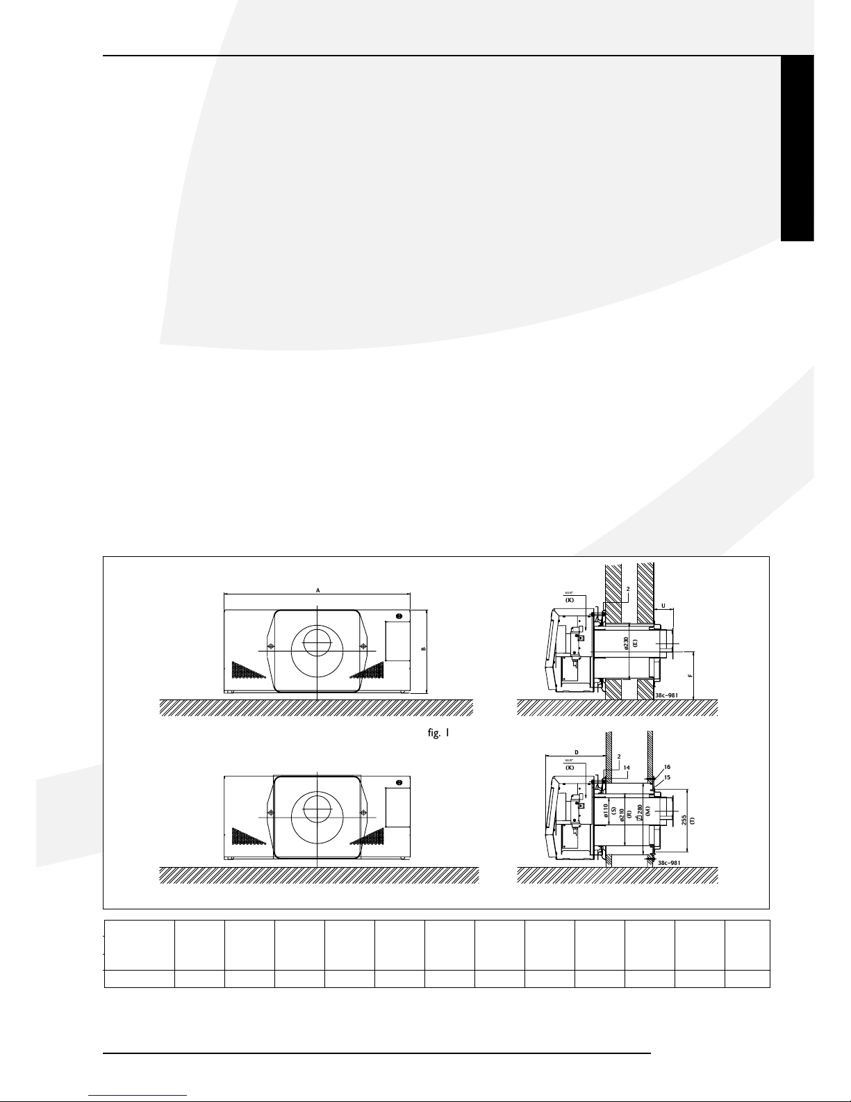
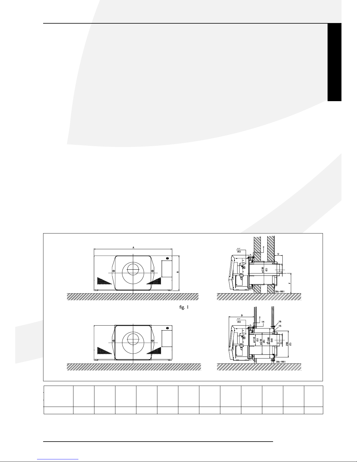
Installatie aan een wand van onbrandbaar
materiaal (fig. 1)
Het toestel kan hangend of staand worden geïnstalleerd.
Houd er rekening mee dat boven het toestel minimaal 1
meter vrij ruimte nodig is voor voldoende warmteafvoer.
Als u het toestel zo laag mogelijk wilt installeren moet
de afstand van het hart van de muurdoorvoer tot aan de
vloer maat F zijn.
Voor het aftekenen van de muurdoorvoering kan de montageplaat (2) als mal worden gebruikt. Om de mantel om
het binnenwerk te kunnen hangen moet men rekening
houden dat tussen een eventuele vensterbank en het toestel een vrije ruimte van minimaal 25 mm noodzakelijk is.
De minimum benodigde vrije installatie hoogte bedraagt
maat Y (tabel 1, blz. 3).
De standaard geveldoorvoer
Maak een horizontaal gat in de muur met een diameter
van ø 230mm (maat E) voor doorvoering van de inlaatpijp. Zorg er voor dat de muurdoorvoer ongeveer 2º op
afschot ligt.
De standaard geveldoorvoer is geschikt voor wanddiktes
van 50-330 mm en de standaard verlengde doorvoer voor
wanddiktes van 50-600 mm. Afhankelijk van de wanddikte
dienen de in- en uitlaatpijp op lengte te worden gemaakt n.l.
• lengte inlaatpijp = wanddikte + 20 mm.
• lengte uitlaatpijp = wanddikte + 70 mm.
De aan het muurrooster gemonteerde trekstangen kunnen
na montage van de geveldoorvoer worden ingekort.
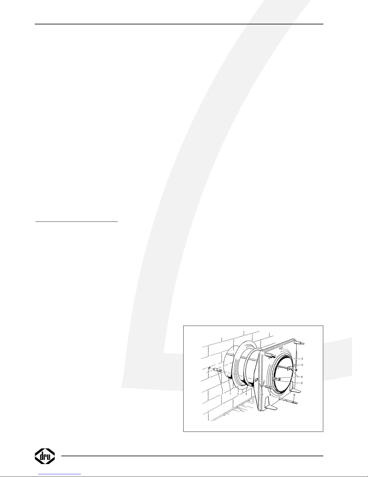
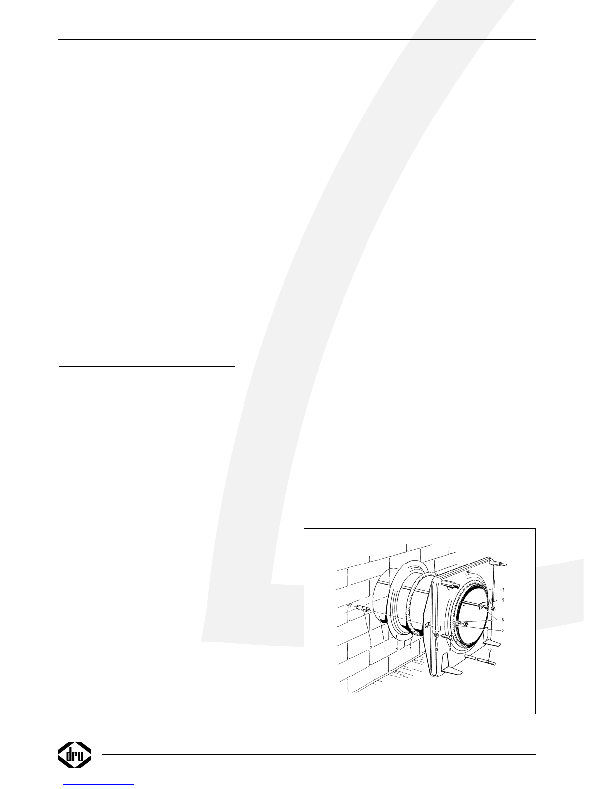
Installatie van de standaard geveldoorvoer
(fig. 3)
Schuif de op lengte gemaakte inlaatpijp (1) door de
montageplaat (2) en zorg daarbij dat de felsnaad tegenover
het merkteken (45˚ links boven) in de montageplaat zit.
Schuif de afdichtring (3) en de muurring (4) om de inlaatpijp en let daarbij op de volgorde. (zie figuur). Neem het
geheel en schuif de inlaatpijp in de muuropening. De
INSTALLATIE VOORSCHRIFT
2
fig. 3
Page 5
Nederlands
montageplaat aandrukken tot tegen de wand. De inlaatpijp terugdrukken zodanig dat het pijpeinde gelijk ligt met
de omgezette rand van de montageplaat.
Plaats vanaf de buitenzijde het muurrooster met de daaraan gemonteerde trekstangen in de inlaatpijp. De trekstangen iets naar buiten buigen zodat deze licht klemmen
in de inlaatpijp waardoor het rooster op z’n plaats blijft.
Het merkteken “Top” boven houden bij het plaatsen van
het muurrooster. Schuif de twee bevestigingsbeugels (5)
over de trekstangen (6) en zorg er daarbij voor dat de
bevestigingsbeugels om de omgehaalde rand van de montageplaat haken. Moeren aanbrengen op de trekstangen
en handvast aandraaien. De bevestigingsbeugels op de
horizontale hartlijn van de inlaatpijp plaatsen. Zie ook de
merktekens in de montageplaat.
De geveldoorvoer met telescopische inlaatpijp
Deze is geschikt voor wanddiktes van 250 - 440 mm
zonder inkorten van de inlaatpijpdelen. Door de pijpdelen
in te korten is deze geveldoorvoer geschikt te maken
voor wanddiktes van 70 tot 250 mm. De uitlaatpijp dient
op lengte te worden gemaakt volgens tabel. De aan het
muurrooster gemonteerde trekstangen kunnen na montage van de geveldoorvoer worden ingekort.
Indien voor wanddiktes van 70 tot 250 mm de telescopische inlaatpijp wordt toegepast dienen beide pijpdelen te
worden ingekort n.l.:
• het inlaatpijpdeel aan de muurroosterzijde gelijk aan de
wanddikte
• het pijpdeel aan de toestelzijde op een lengte = de wanddikte - 20 mm.
LET OP: de pijpdelen niet afknippen aan de zijde waar
de bevestigingsbeugeltjes zijn aangebracht.
Installatie van de geveldoorvoer met telescopische inlaatpijp (fig. 3)
Breng het muurrooster met de daaraan gemonteerde
inlaatpijphelft van buitenaf in de gemaakte muuropening
met “Top” naar boven bij het plaatsen van het muurrooster. Schuif de andere helft van de inlaatpijp door de
montageplaat (2) en zorg daarbij dat de ingelaste bevestigingsbeugels (5) op de horizontale hartlijn liggen (zie
de merktekens in de montageplaat) en om de omgezette
montageplaatrand haken.
Breng de afdichtring (3) en de muurring (4) aan om de
inlaatpijp helft (Zie de figuur voor de juiste volgorde).
Neem het geheel en schuif de inlaatpijp helft van binnenuit door de gemaakte muuropening in het reeds
aangebrachte inlaatpijp deel. Zorg daarbij dat de twee
trekstangen (6) door de bevestigingsbeugels (5) steken.
De montageplaat aandrukken tot tegen de wand. Breng
de moeren aan op de trekstangen (6) en zet deze tegen
de bevestigingsbeugels (5) handvast.
INSTALLATIE VOORSCHRIFT
;
;;;
;
;
;;
;
;
;
;
;
;;;
;
;
;
;
;
;
;
;;
;
;
;
;
;
;
;
;;;
;
;;
;
;
;
;
;
;;
;
;
;
;
;
;
;
;;
;;
;;
;
;
;
;;
;;
;
;;;;
;
2
G3/8"
(K)
ø230
U
F
A
B
38c-981
(E)
16
14
2
15
G3/8"
(K)
255
ø110
280
ø210
D
38c-981
(T)
(S)
(R)
(M)
fig. 1
fig. 2
NL 31 / NL 51
Tabel 1
Type A B D E F K M R S T U Y
NL31 757 339 232 ø 230 167 3/8” 280 Ø210 Ø110 255 79 364
NL31 STYLE 805 390 230 ø 230 192 3/8” 280 Ø210 Ø110 255 79 364
NL51 1228 386 289 ø 230 183 3/8” 280 Ø210 Ø110 255 80 401
3
Page 6
Bevestiging van de montageplaat (fig. 3)
Let op: stel de montageplaat (2) waterpas, zorg ervoor dat
de inlaatpijp naar buiten toe afloopt (1cm op 1 m) en dat
het muurrooster recht tegen de buitenmuur ligt. Eventueel
condenswater zal dan nooit in het toestel kunnen lopen.
• Draai de moeren op de trekstangen vast.
• Zaag of knip de trekstangen af zodat deze niet buiten de
bevestigingsbeugels (5) uitsteken.
• Boor het gat voor de plug / keilmoer (7).
• Breng de plug / keilmoer aan in de muur.
• Bevestig de montageplaat m.b.v. de schroef / bout (8),
incl. sluitring (9).
Installatie aan een wand van brandbaar
materiaal (fig. 2)
Wanneer het toestel aan een wand van brandbaar
materiaal wordt geïnstalleerd dient de wanddoorvoer als
volgt te worden uitgevoerd.
• Maak ter plaatse van de doorvoering een vierkante opening in de wand ( 280mm).
• Bij samendrukbare wanden de ruimte rondom goed opvullen zodat de wand niet kan worden ingedrukt.
• De bout / schroef (8) (fig. 3) vervangen door b.v. een
houtdraadbout.
• Plaats aan de kamerzijde tussen de montageplaat (2) en de
wand stralingsplaat 14.
• Bevestig aan de buitenzijde van de wand m.b.v.
4 schroeven (16) siluminplaat 15.
De stralingsplaat 14 en siluminplaat 15 zijn samen verpakt
en te bestellen bij uw leverancier. De montage van de
muurdoorvoer is verder zoals hiervoor beschreven.
N.B. Voor de berekening van de lengte van de in- en uitlaatpijp dient ook de dikte van siluminplaat 15 te worden
meegeteld.
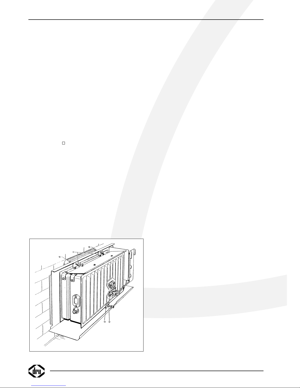
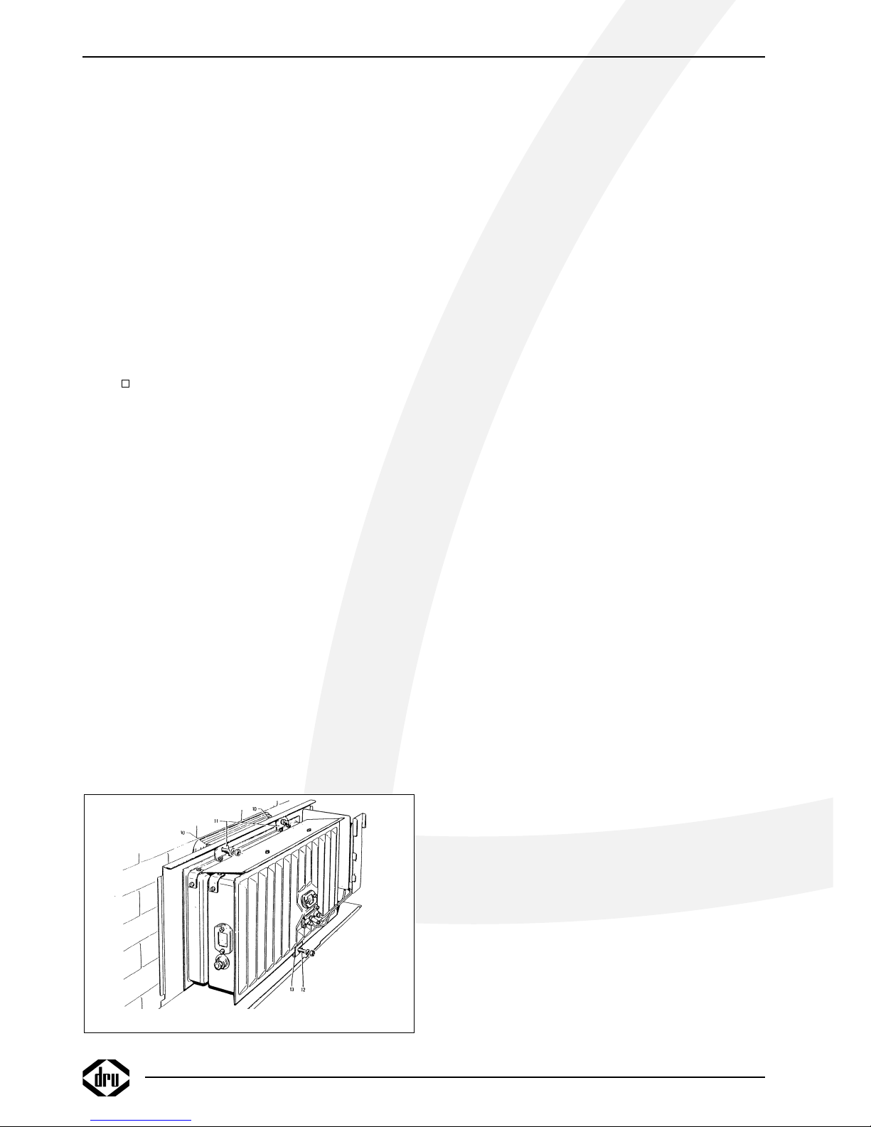
Installatie van het binnenwerk (fig. 4)
Schuif de op lengte gemaakte uitlaatpijp in de roosteropening. Schuif de twee siliconen rubber tulen (verpakt bij
het glaswolkoord) over de bouten (10) en in de gaten van
de achterplaat.
Neem het binnenwerk en zet deze met de onderrand op
de twee steunen van de montageplaat. Houd het binnenwerk in evenwicht en schuif de uitlaatpijp een klein stukje
in de uitlaatopening van het binnenwerk ter ondersteuning.
Schuif nu het binnenwerk tegen de montageplaat en zorg
er daarbij voor dat de omgezette montageplaatrand in de
inlaatbus op de achterzijde van het binnenwerk valt en de
bouten (10) door de beugels (11) steken. Moeren en sluitringen op de bouten (10) aanbrengen en vast aandraaien
tot tegen de aanslag. Daarna de draadstang (12) in de
beugel (13) schuiven. Moer met sluitring op de draadstang
(12) aanbrengen en aandraaien tot het binnenwerk parallel
met de wand staat.
N.B. Wanneer gemakkelijk toegankelijk, b.v. op de begane
grond, kan de uitlaatpijp ook van buitenaf worden aangebracht nadat de roosterbinnenplaat en de korf zijn gedemonteerd.
Aansluiting van de gastoevoer
De aansluiting is 3/8” BSP binnendraad. Indien de toevoerleiding door de achterplaat het toestel binnenkomt moet
men het plaatje uitdrukken. Gebruik in de toevoerleiding
een gekeurde aansluitkraan met koppeling (voor Belgie
moet deze B.G.V. gekeurd zijn). De aansluitkraan met koppeling dient buiten de mantel te worden geplaatst. Verder
geldt:
• Ontlucht de toevoerleiding voordat het toestel wordt
vastgekoppeld.
• De bedieningskraan mag niet verdraaid worden bij het
aansluiten aan de gastoevoerleiding.
• Vermijd spanningen op de bedieningskraan en leidingen.
• Controleer de aansluitingen op gasdichtheid.
4
INSTALLATIE VOORSCHRIFT
fig. 4
Page 7
In bedrijf stellen
Het toestel is door de fabriek ingericht voor de gassoort
zoals op het typeplaatje is aangegeven.
De thermostaat regelt modulerend tussen ,volstand” en
,kleinstand” en bij een geringe warmtebehoefte in twee
posities, n.l. ,kleinstand” of ,uit”. Hierbij blijft de waakvlam
steeds branden. De kleinstand kan alleen worden gecontroleerd wanneer de kamertemperatuur hoger is dan ca.
15° C (60° F).
Kleinstand
De kleinstand is ingesteld op ± 20 % van het volverbruik.
De kleinstandschroef is geheel ingedraaid en voorzien van
de juiste kleinstandboring. Deze is niet instelbaar.
Waakvlambrander
De waakvlambrander heeft bij levering het juiste verbruik
d.m.v. een spuitstuk dat zich in de waakvlambrander bevindt.
De waakvlambrander behoeft niet te worden ingesteld.
Plaatsen van de mantel
Hang de mantel aan de bovenzijde over de achterplaat
(zijkanten van de mantel blijven voor de achterplaat) en
zorg daarbij dat de bedieningsknoppen in de daarvoor
bestemde mantelopening vallen.
Belangrijk
Een ingebouwde veiligheidsvergrendeling treedt in werking
wanneer het toestel op ,,UIT” (gesloten stand) wordt
gezet. Wacht daarom 5 minuten alvorens het toestel
opnieuw te ontsteken. Probeer binnen deze tijd niet de
aansteekknop in te drukken, daar deze door de veiligheidsvergrendeling geblokkeerd is. Forceer de knop niet, omdat
het mechanisme dan kan worden beschadigd.
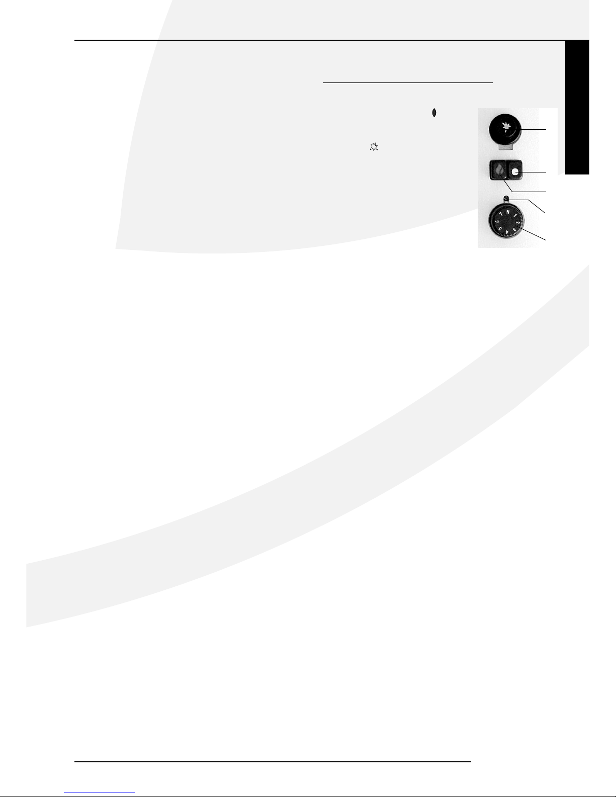
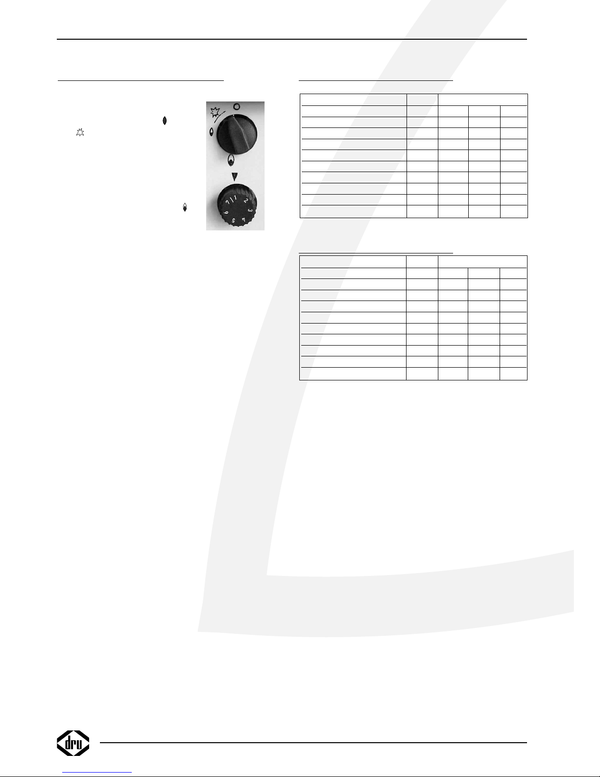
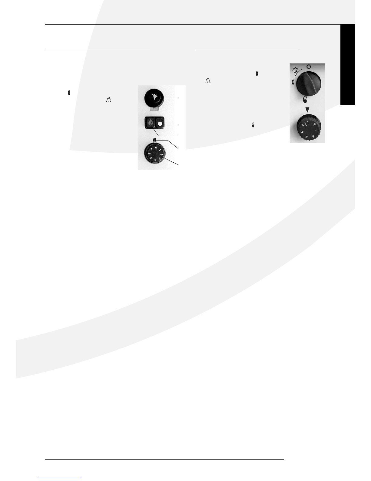
GEBRUIKERSHANDLEIDING NL 31
Aansteken
De druktoets A (symbool )
indrukken en ingedrukt houden.
Daarna tevens de ontsteektoets E
(symbool ) één of twee maal
indrukken waardoor de waakvlambrander ontstoken wordt.
Controleer of de waakvlam brandt.
(achter het glasraampje aan de voorzijde). Indien de waakvlam brandt, de
druktoets A nog ca. 10 sec. geheel
ingedrukt houden. Daarna toets A
loslaten en controleren of de waakvlam blijft branden. Afhankelijk van
de stand van de thermostaatknop D
en de kamertemperatuur kan de hoofdbrander onmiddellijk na het loslaten van toets A door de waakvlam ontstoken worden.
Temperatuur regelen
De stand van de thermostaatknop D bepaalt de temperatuur in de kamer. Stand 7 (met 7 tegenover het indicatiepunt C) geeft de hoogste temperatuur en stand 1 de laagste.
De thermostaat regelt modulerend tussen “volstand” en
“kleinstand” van de brander en bij een kleine warmtebehoefte tussen “kleinstand” en “N”.
De thermostaat houdt de kamer automatisch op de
gewenste ingestelde temperatuur.
Het is geen enkel bezwaar om het toestel ‘s nachts te
laten doorbranden; het is volledig beveiligd.
De thermostaat is voorzien van een vorstbeveiliging. Dit is
stand N op de thermostaatknop D. Bij een omgevingstemperatuur van onder de 10ºC wordt het ventiel automatisch geopend, waardoor het toestel de ruimte verwarmd
tot 10ºC. Indien dit niet gewenst is, dient het toestel uitgeschakeld te worden
Uitschakelen
Druktoets B (met symbool o ) indrukken. De gastoevoer
naar de hoofd- en de waakvlambrander is dan gesloten.
Nederlands
INSTALLATIE VOORSCHRIFT GEBRUIKERSHANDLEIDING
NL 31 / NL 51
E
B
A
C
D
5
Page 8
GEBRUIKERSHANDLEIDING NL 51
Aansteken
Knop A indrukken en linksom
draaien tot de kleine vlam .
Bij
zal het toestel ontsteken.
Controleer of de waakvlam achter
het kijkglas brandt. Indien de waakvlam brandt, knop A nog ca. 5 sec.
geheel ingedrukt houden. Daarna
knop A loslaten en controleren of
de waakvlam blijft branden. Draai
nu knop A naar de grote vlam .
Hierdoor zal de hoofdklep van het
regelblok opengaan.
Temperatuur regelen
Door regelknop B linksom te draaien (naar stand 7) zal
de ingestelde temperatuur hoger worden, door de knop
rechtsom te draaien (naar stand 1) zal de ingestelde temperatuur lager worden. De thermostaat regelt modulerend
tussen volstand en kleinstand en houdt het vertrek op de
door u ingestelde temperatuur. Het toestel kan onbeheerd
blijven branden omdat het volledig is beveiligd.
Waakvlamstand
Wanneer de kachel niet gebruikt wordt maar wel de
waakvlam moet branden kan knop A naar de kleine vlam
worden gedraaid. Hierdoor wordt de gastoevoer naar de
hoofdbrander afgesloten.
Uitschakelen
Draai knop A naar de “ 0 “ stand. De gastoevoer naar de
branders is dan gesloten.
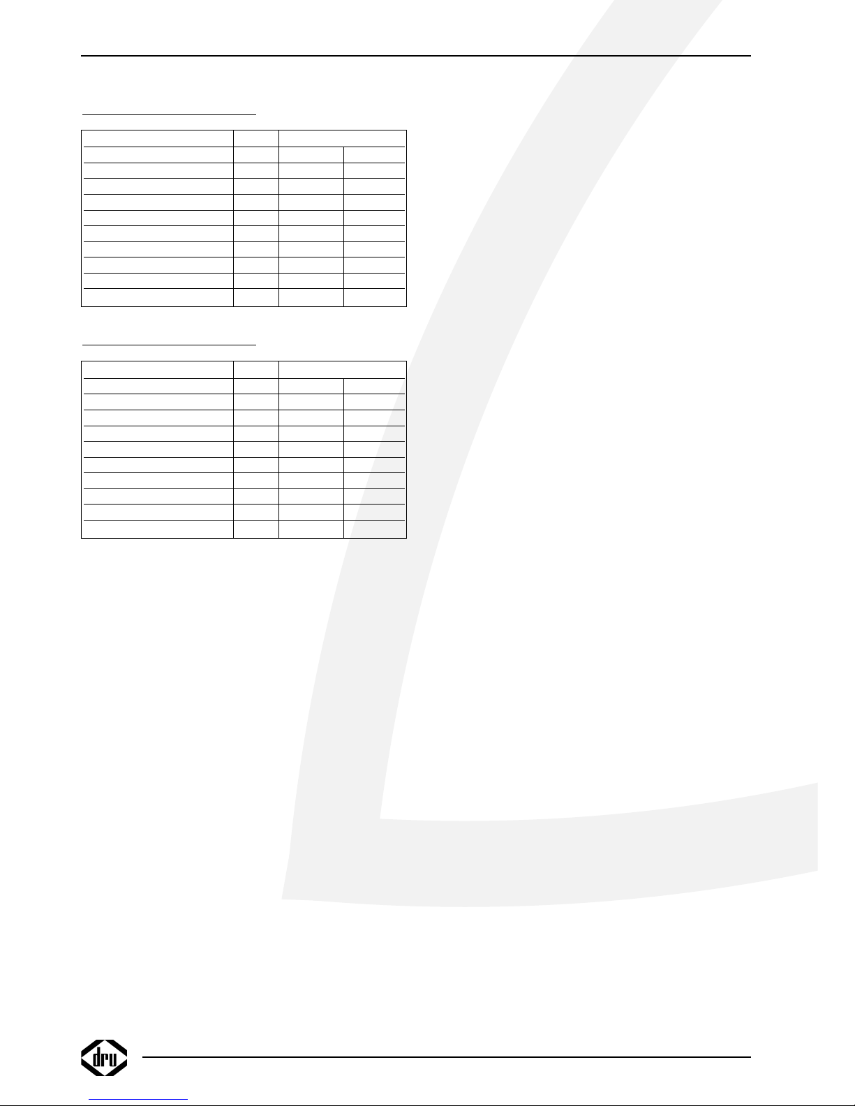
TECHNISCHE GEGEVENS NL 31
TECHNISCHE GEGEVENS NL 51
GEBRUIKERSHANDLEIDING
6
A
B
Type C11
Gassoort G20 G25 G31
Branderdruk mbar 20 24 30
Nom. Belasting (Hs) kW 4.00 3.70 4.00
Nom. Belasting (Hi) kW 3.60 3.33 3.60
Nom. Vermogen kW 3.06 2.853 3.06
Verbruik volstand m
3
/h 0.381 0.401 0.150
Verbruik kleinstand m3/h 0.104 0.103 0.034
Branderspuitstuk Mm Ø 1.45 1.45 1.05
Waakvlamspuitstuk kode 51 51 30
Kleinstelspuitstuk Mm Ø 0.75 0.75 0.50
Type C11
Gassoort G20 G25 G31
Branderdruk mbar 10.5 13.6 21
Nom. Belasting (Hs) kW 7.30 6.70 7.30
Nom. Belasting (Hi) kW 6.60 6.04 6.60
Nom. Vermogen kW 5.70 5.085 5.70
Verbruik volstand m3/h 0.690 0.726 0.270
Verbruik kleinstand m3/h 0.180 0.225 0.081
Branderspuitstuk Mm Ø 2.25 2.25 1.55
Waakvlamspuitstuk kode 51 51 30
Kleinstelspuitstuk Mm Ø 1.00 1.00 0.80
Page 9

Nederlands
ALGEMENE OPMERKINGEN
Onderhoud en reiniging
Uw toestel dient eenmaal per jaar door een gekwalificeerd
bedrijf te worden gecontroleerd, en waar nodig, hersteld
of gereinigd. De controle en het onderhoud dient in ieder
geval een goede en veilige werking van het toestel te
omvatten. U kunt hiervoor gebruik maken van uw gasinstallateur of een gespecialiseerd onderhoudsbedrijf. Het
verdient aanbeveling om vóór en tijdens het stookseizoen
het toestel enkele malen stofvrij te maken. Bij het reinigen van de mantel geen bijtende of schurende middelen
gebruiken. Lakbeschadigingen, bijvoorbeeld door het plaatsen van voorwerpen op of tegen de mantel, vallen buiten
de garantie.
Let op: Bij het vervangen van het thermokoppel moet
de wartel in het gasregelblok handvast gedraaid worden,
waarna deze met een steeksleutel een kwartslag aangedraaid moet worden.
Verkleuring van wanden en plafonds
Bruinverkleuring is een vervelend probleem en is moeilijk
op te lossen. Bruinverkleuring kan worden veroorzaakt
door onder andere stofverbranding veroorzaakt door te
weinig ventilatie, door het roken van sigaretten of het
branden van kaarsen.
Deze problemen kunnen worden voorkomen door:
Het vertrek waar het toestel zich bevind goed te ventileren. Een goede richtlijn hiervoor is (vlg. het Nederlands
Bouwbesluit):
Bij nieuwbouw : 3.24 m
3
/ uur per m2
vloeroppervlak van een vertrek.
Bij bestaande bouw : 25.20 m2 / uur voor een vertrek.
Maak zo weinig mogelijk gebruik van kaarsen en olielampjes en houd het verbrandingslontje zo kort mogelijk. Deze
“sfeerbrengers” zorgen voor aanzienlijke hoeveelheden
vervuilde en ongezonde roetdeeltjes in uw woning. Rook
van sigaretten en sigaren bevat o.a. teerstoffen die bij
verhitting eveneens op koudere en vochtige muren zullen
neerslaan. Bij een nieuw gemetselde schouw of na een verbouwing wordt aanbevolen minimaal 6 weken te wachten
voordat men gaat stoken, het bouwvocht moet namelijk
geheel verdwenen zijn uit wanden, vloer en plafond.
Eerste maal stoken
Tijdens de eerste maal stoken kan er een onaangename
geur ontstaan, die wordt veroorzaakt door het uitdampen
van de lak. Dit verdwijnt na enkele uren. Daarom raden
wij u aan het toestel de eerste maal op de hoogste stand
te stoken terwijl u tevens het vertrek waarin de kachel
staat goed ventileert.
Extra bescherming
Indien het toestel in een vertrek geïnstalleerd wordt waar
jonge kinderen of hulpbehoevende mensen zonder toezicht verblijven, is het wenselijk het toestel af te schermen.
Afdanken
Indien u het toestel vervangt of verwijdert, moet u het
toestel via de reguliere weg afvoeren. Voordat tot demontage wordt overgegaan eerst de aansluitkraan met koppeling dichtdraaien. De koppeling tussen aansluitkraan
en toestel losdraaien. Het gehele toestel kan nu worden
gedemonteerd en afgevoerd.
Garantie
De garantie op uw DRU toestel wordt verleend via uw
leverancier. In geval van storingen dient u altijd met hem
contact op te nemen. Uw leverancier zal DRU inschakelen
indien hij dit noodzakelijk acht. De fabrieksgarantie op uw
toestel bedraagt 2 jaar na datum van aankoop.
ALGEMENE OPMERKINGEN
NL 31 / NL 51
7
Page 10

8
Page 11

CONTENTS
CONTENTS
Foreword .............................................................................10
Unpacking .............................................................................10
Connection ..........................................................................10
Instructions for installation ..............................................10
Type of gas ...........................................................................10
Important .............................................................................10
General .................................................................................10
Installing the heater against a wall of
incombustible material ......................................................10
The standard wall duct .....................................................10
Installation of the standard exterior wall duct ...........10
The exterior wall duct with telescopic inlet pipe ......11
Installation of the wall duct with
telescopic inlet pipe ...........................................................11
Fastening the mounting sheet .........................................12
Installation to a wall of inflammable material ..............12
Connection of the gas supply ........................................12
Operations ...........................................................................12
The low setting ...................................................................12
Pilot light burner ................................................................12
Placing the housing .............................................................12
Important .............................................................................12
Operating instructions NL 31 .........................................13
Lighting ..................................................................................13
Temperature controle ......................................................13
Pilot light setting .................................................................13
Switching off ........................................................................13
Operating instructions NL 51 .........................................13
Lighting ..................................................................................13
Temperature controle ......................................................13
Pilot light setting .................................................................13
Switching off ........................................................................13
Technical data NL 31 ........................................................14
Technical data NL 51 ........................................................14
General notes .....................................................................15
Gas safety regulations (for installation & use), 1998 .15
Cleaning and Maintenance................................................15
Discoloration of walls and ceiling ..................................15
Lighting the heater for the first time.............................15
Extra protection .................................................................15
Disposal ................................................................................15
Guarantee ............................................................................15
English
NL 31 / NL 51
9
Page 12
Foreword
Dear Customer,
We would like to thank you for buying this DRU product. Our products have been designed and produced to
meet the highest possible quality, performance and safety
requirements, allowing you to enjoy years of problem-free
use.
In this booklet you will find instructions for the installation
and use of your new appliance. Please read these instructions and the manual carefully to familiarize yourself with
the appliance. If you require any further support, please do
not hesitate to contact your supplier.
Unpacking
Once the heater has been unpacked, all packaging should
be disposed of in the regular manner.
Connection
This appliance should be connected by a registered
installer.
INSTRUCTIONS FOR INSTALLATION
Type of gas
This appliance can only be used and is only suitable for the
country and the type of gas mentioned on the type identification tag. Please check that the local gas and pressure
correspond with the specifications on the type identification tag. All regulations regarding gas installation, including
any local regulations, must be observed at all times. The
appliance is to be installed by a registered installer.
To operate the heater on bultane or propane, it should be
converted by a registered installer. A conversion set can
be ordered through him.
Important
• Keep curtains and any other flammable materials at least
50cm away form the appliance.
• Caution! Touching the heater when hot can cause burns
and blisters!
• The appliance should be installed and maintained by a
registered installer.
• Do not install any so-called dust filter on or under the
casing.
• Do not hang wet clothes and towels etc. on the heater to
dry.
General
The appliance can be mounted either on a wall of incombustible material (e.g. stone or concrete) or on a wall of
combustible material (e.g. wood).
Installing the heater against a wall of
incombustible material (fig. 1)
The appliance can be installed in a hanging or standing
position. Allow at least 1 metre’s clearance above the
heater to enable sufficient heat circulation. If you want to
install the appliance as low as possible, the distance from
the centre of the wall duct to the floor should be dimension F (table 1, page 9).
The mounting plate (2) serves as a stencil to mark the
position of the duct. To be able to hang the casing over
the interior, a minimal clearance of 25 mm must be allowed between the appliance and a windowsill or suchlike.
The minimum total free height for installation is dimension
Y (table 1, page 9).
The standard wall duct
Drill a horizontal hole in the wall, ø 230mm (E) in diameter, to take the air-supply pipe. The wall duct should
slope at an angle of approx. 2º.
The standard wall duct is suitable for walls with a thickness of 50 – 330 mm and the standard extended wall duct
for walls with a thickness of 50 – 600 mm. Depending on
the thickness of the wall, the inlet and outlet pipes should
be made to length, i.e.:
• length inlet pipe = wall thickness + 20 mm.
• length outlet pipe = wall thickness + 70 mm.
The tension members fixed to the wall grid can be made
to size after installation
Installation of the standard exterior wall duct
(fig. 3)
Slide the adjusted inlet pipe (1) through the mounting
sheet (2), with the turned-back edge facing the mark (45º
top left) in the mounting sheet. Slide the sealing ring (3)
and the wall ring (4) around the inlet pipe, paying attention to the order (see figure). Take the whole and slide
the inlet pipe into the wall opening. Press the mounting
10
INSTRUCTIONS FOR INSTALLATION
fig. 3
Page 13
English
INSTRUCTIONS FOR INSTALLATION
sheet up to the wall. Press the inlet pipe back in such a
way that the end of the pipe is level with the turned-back
edge of the mounting sheet.
From the outside, bring the wall grid with its attached
tension members into the inlet pipe. Bend the tension
members a little outwards, so that they will jam slightly
in the inlet pipe, keeping the grid in its place. Keep the
mark “Top” up when placing the wall grid. Slide the two
fastening clamps (5) over the tension members (6), taking
care that the fastening clamps catch on the turned-back
edge of the mounting sheet. Fix the screw-nuts onto the
tension members and tighten them by hand. Place the fastening clamps onto the horizontal centre line of the inlet
pipe. See also the marks in the mounting sheet.
The exterior wall duct with telescopic inlet
pipe
This is suitable for wall thicknesses of 250 – 440 mm
without shortening the parts of the inlet pipe. By shortening the pipe’s parts, this exterior wall duct can be
adapted for thicknesses of 70 – 250 mm. The outlet pipe
should be adjusted. The tension members attached to
the wall grid can be shortened after the wall duct has
been mounted. If the telescopic inlet pipe is applied for
wall thicknesses of 70 – 250 mm, both parts of the pipe
should be shortened, i.e.:
• the part of the inlet pipe on the side of the wall grid
equal to the thickness of the wall
• the part of the pipe on the side of the heater to a length
equalling the wall thickness minus 20 mm.
CAUTION: do not cut the pipe parts on the side
where the fastening clamps have been applied.
Installation of the wall duct with telescopic
inlet pipe (fig. 3)
From the outside, put the wall grid, together with the
attached half inlet pipe into the created wall opening,
keeping “Top” up when placing the wall grid. Slide the
other half of the inlet pipe through the mounting sheet
(2), making sure that the inserted fastening clamps (5)
lie on the horizontal centre line (see the marks in the
mounting sheet). They should catch on the turned-back
edge of the mounting sheet.
Attach the sealing ring (3) and the wall ring (4) to the
half inlet pipe (see ffigure for the correct order). Take
the whole and, from the inside, slide the half inlet pipe
through the created wall opening into the part of the
inlet pipe already mounted. While doing so, make sure
the the two tension members (6) stick through the fastening clamps. Press the mounting sheet up to the wall.
Appply the screw-nuts onto the tension members (6) and
tighten them by hand against the fastening clamps (5).
NL 31 / NL 51
;;;;
;
;;;
;
;
;
;
;;
;
;
;
;
;
;
;
;;;
;
;
;
;
;
;;;
;
;
;
;
;
;
;
;
;
;
;;
;
;;
;
;
;
;
;;;
;
;
;
;
;
;;
;;
;
;;
;;
;
2
G3/8"
(K)
ø230
U
F
A
B
38c-981
(E)
16
14
2
15
G3/8"
(K)
255
ø110
280
ø210
D
38c-981
(T)
(S)
(R)
(M)
fig. 1
fig. 2
Table 1
Type A B D E F K M R S T U Y
NL31 757 339 232 ø 230 167 3/8” 280 Ø210 Ø110 255 79 364
NL31 STYLE 805 390 230 ø 230 192 3/8” 280 Ø210 Ø110 255 79 364
NL51 1228 386 289 ø 230 183 3/8” 280 Ø210 Ø110 255 80 401
11
Page 14
Fastening the mounting sheet (fig. 3)
Caution: Level the mounting sheet, make sure that the
inlet pipe goes down towards the outside. (1 cm to 1 m)
and that the wall grid lies straight against the exterior wall.
Then, any condensation will never get into the heater
because of the downwards flow of the pipe.
• Now tighten the screw nuts on the tension members
• Saw or cut the tension members so that they do not stick
out from the fastening clamps (5).
• Drill the hole for the key bolt (7).
• Attach the key bolt and attach the mounting sheet using
the bolt (8) and washer (9).
Installation to a wall of inflammable material
(fig. 2)
When the appliance is installed to a wall of flammable
material, the wall duct should be executed as follows.
• On the spot of the duct, create a square opening in the
wall ( 280 mm).
• In the case of compressible walls, fill up the space all
round the opening well, so that the wall cannot be
crushed.
• In addition, replace the bolt (8) (fig 3) by e.g. a wood
screwed bolt.
• On the room side, put the heat shield (14) between the
mounting sheet (2) and the wall.
• On the outside of the wall, using 4 screws (16), attach
siluminplate (15).
The heat shield (14) and the silumin plate (15) are packed
together and are available from your dealer. Assembling
the wall duct is otherwise the same as previously
described.
N.B. To calculate the length of the inlet and outlet pipe,
the thickness of siluminplate (15) should be included.
Installation of the interior (fig.4)
Slide the adjusted outlet pipe into the gird opening. Slide
the two Silicon Rubber Tulles (packed with the glass silk
rope) over the bolts (10) and into the holes of the back
plate.
This prevents possible dirt and deposit from settling onto
the wall. Take the interior and put it with the bottom
edge on the two supports of the mounting sheet. Keep
the interior balanced and slide the outlet pipe a little bit
into the outlet opening of the interior for support. Now
slide the interior against the mounting sheet, taking care
that the turned-back edge of the mounting sheet fits into
the inlet bush on the back side of the interior and that
the bolts (10) stick through the clamps (11). Attach screw
nuts and washers to the bolts (10) and tighten closely up
to the stop. Then slide the screw spindle (12) into the
clamp (13). Fix the screw nut and washer to the screw
spindle (12) and tighten until the interior is standing parallel to the wall.
N.B. If easy accessible, e.g. on the ground floor, the outlet
pipe can also be mounted from the outside after the grid
interior sheet and the basket have been disassembled.
Connection of the gas supply
The connection has a 3/8” BSP inside thread. If the supply
pipe enters the appliance through the back plate, press out
the disc in the plate. An approved connecting tap with
coupling should be used in the supply pipe (For Belgium
this should be B.G.V. approved). The connecting tap with
coupling should be fitted outside the casing. Furthermore:
• Expel all air from the supply pipes/hoses before coupling
to the appliance.
• Do not turn the coupling tap when connecting it to the
gas supply.
• Avoid any pressure on the control tap and pipes.
• Check that all connections are gastight.
Operations
The manufacturer has made the appliance suitable for the
type of gas as indicated on the type identification tag. The
thermostat regulates modulatingly between “full power
setting” and “low power setting” and , when little heat is
required, in two settings, i.e. “low” or “off”. In this situation, the pilot light keeps burning. The “low” setting can
only be checked when the room temperature is higher
than ± 15°C (60°F).
The low setting
The low setting has been adjusted to ± 20% of the full
consumption. The low setting screw has been fully tightened and is supplied with the correct low setting bore.
This is not adjustable.
Pilot light burner
Upon delivery, the pilot light burner has the correct consumption by means of a nozzle inside the pilot light burner. The pilot light burner needs no adjustment.
Placing the housing
Hang the top of the casing over the back plate (the sides
of the casing remain in front of the back plate) and ensure
that the control buttons drop into the appropriate recess
in the casing.
Important
A built-in safety lock is activated when the appliance is
switched to “OFF” (closed down setting). Therefore, wait
5 minutes before relighting the heater. Within this period, do not try to push the lighting button, as this has been
blocked by the safety lock. Do not force the button, as
this may result in damage to the mechanism.
12
INSTRUCTIONS FOR INSTALLATION
fig. 4
Page 15
OPERATING INSTRUCTIONS NL 31
The buttons to operate the appliance have been placed
behind the flap on the righthand side of the heater front.
Lighting
Press and hold button A (with the
symbol
). Press the ignition button E (with the symbol ) once
or twice to light the pilot burner.
Check that the pilot flame is alight
(behind the glass on the front).
Once the pilot light is burning, hold
button A for another 10 seconds.
Then release button A and check
that the pilot light is still burning.
The main burner could be ignited
by the pilot light immediately after
button A has been released, depending on the thermostat setting, button
D, and the room temperature.
Temperature control
The thermostat setting, button D, will determine the
temperature in the room. Setting 7 - with ‘7’ opposite the
indicator (C) - will give the highest temperature and setting 1 the lowest. The thermostat regulates the heater in
modulation between HIGH and LOW burner settings and,
if only a little warmth is required, between LOW and N.
The thermostat automatically keeps the room at the
required temperature.
There is absolutely no objection to the appliance staying
on overnight, it is fully protected.
The thermostat has a frost-protection setting. This is setting N on the thermostat control D. If the ambient temperature drops below 10 ºC, the valve will automatically
open; the heater will then heat the room to 10 ºC. If this
is not required, the heater should be switched off.
Switching off
Press button B (with the symbol o ). The gas supply to
both the main and the pilot burners is then switched off.
OPERATING INSTRUCTIONS NL 51
Lighting
Press button A and turn to the left
towards the small flame
.
At the heater will ignite. Check if
the pilot light burns behind the window. If the pilot burns, keep
button A pressed fully down for
another 5 seconds. Then release
button A and check if the pilot light
keeps burning. Now turn button A
towards the big flame . This will
open the main valve of the regulation
block.
Temperature control
By turning control button B to the left (to mark 7), the
set temperature will rise, by turning the button to the
right (towards mark 1), the set temperature will fall. The
thermostat regulates modulatingly between full power
setting and low power setting and keeps the room at the
temperature set by you. The heater can be kept burning
uncontrolled as it is fully protected.
Pilot light setting
When the heater is not in use, but the pilot light has to be
kept burning, button A can be turned towards the small
flame. In this way, the gas supply to the main burner will
be disconnected.
Switching off
Turn button A towards the “0” setting. The gas supply to
the burners will then be disconnected.
English
OPERATING INSTRUCTIONS
NL 31 / NL 51
E
B
A
C
D
A
B
13
Page 16
TECHNICAL DATA NL 31
TECHNICAL DATA NL 51
OPERATING INSTRUCTIONS
14
Type C11
Type of gas G20 G31
Burner pressure mbar 10.5 21
Nom. Load (Hs) kW 7.30 7.30
Nom. Load (Hi) kW 6.60 6.60
Nom. output kW 5.70 5.70
Consumption on full output m3/h 0.690 0.270
Consumption on low output
m3/h 0.180 0.081
Burner injector Mm Ø 2.25 1.55
Pilot light injector kode 51 30
Low setting injector Mm Ø 1.00 0.80
Type C11
Type of gas G20 G31
Burner pressure mbar 20 37
Nom. Load (Hs) kW 4.00 4.00
Nom. Load (Hi) kW 3.60 3.60
Nom. output kW 3.06 3.06
Consumption on full output m3/h 0.381 0.151
Consumption on low output
m3/h 0.104 0.043
Burner injector Mm Ø 1.45 1.00
Pilot light injector kode 51 30
Low setting injector Mm Ø 0.75 0.50
Page 17

English
GENERAL NOTES
Gas Safety Regulations (for installation & use) 1998
In your own interest and that of safety, it is law that
all gas appliances are installed by competent persons in
accordance with the above regulations. Failure to install
appliances correctly could lead to prosecution.
NB: The Confederation of Registered Gas
Installers, whose members are identified by the
emblem shown here, are all required to work to
the recognised standards.
Cleaning and Maintenance
The appliance should be inspected once a year by a
qualified company, and cleaned and/or repaired as necessary.The inspection and maintenance must at least ensure
that the appliance is working correctly and safely.This
can be done by your own gasinstaller or a specialised
maintenance company. You are recommended to free the
heater of dust before and occasionally during the heating
season.Do not use abrasives when cleaning the heater.
Damage to the casing varnish, caused by anything being
put on the appliance, is not covered by the guarantee.
NB: When replacing the pilot light burner, the coupling
nut in the gas control block should first be tightened by
hand and then tightened a quarter-turn with an
open-ended spanner.
Discoloration of walls and ceiling
Brown discoloration is an annoying problem, which is
difficult to solve. It can be caused by dust burning as a
result of poor ventilation, for example, or by cigarette
smoke or candles.
These problems can be avoided by ensuring that the
room the heater is in is properly ventilated. A good
guideline for ventilation is:
New buildings : 3.24 m3 / hour per m2 floor
surface of the room.
Existing buildings : 25.20 m
2
/ hour for a room.
Use candles and oil lamps as little as possible, keeping the
wick as short as possible. While they enhance the atmosphere, candles and oil lamps also cause the formation of
large quantities of unhealthy soot particles in your home.
Cigarette and cigar smoke contains tar, which upon heating will precipitate on cold or damp walls. If you have a
newly cemented chimney or have had any other reconstructions / renovations done, you are advised to wait at
least 6 weeks before lighting your fire, to allow the walls,
floor and ceiling to dry out completely.
Lighting the heater for the first time
There can be an unpleasant smell when you light the
heater for the first time. This is caused by the varnish
evaporating and will disappear after a few hours. We
therefore advise you, on initial use, to heat the appliance at the highest setting while ventilating the room it is
installed in well.
Extra protection
This heater meets the normal safety standards regarding
surface temperatures, but physical contact with heated
surfaces should be avoided where possible. An additional
guard is recommended to protect young children and
elderly, infirmed or handicapped people.
Disposal
When replacing or otherwise removing the appliance, it
should be disposed of in compliance with current regulations.
Shut off the connecting tap with coupling before commencing disassembly. Undo the coupling between the
connecting tap and the appliance. The whole appliance
can now be disassembled and removed.
Guarantee
The warranty for your DRU appliance will be provided by
your supplier. In case of malfunctions, you should always
contact him. You supplier will contact DRU if he feels this
is necessary. The factory warranty for your appliance is
valid for 2 years after date of purchase.
GENERAL NOTES
NL 31 / NL 51
15
Page 18

16
Page 19

Deutsch
INHALT
Einige kurze Worte ...........................................................18
Auspacken ............................................................................18
Anschluss ..............................................................................18
Installationsvorschrift ........................................................18
Gassorte ...............................................................................18
Wichtig .................................................................................18
Allgemein ..............................................................................18
Installation an eine Wand von nicht brennbarem
Material .................................................................................18
Giebeldurchfuhr in Standardausführung .......................18
Installation der Standard Giebeldurchführung ............19
Giebeldurchführung met Teleskopeinlassrohr ............19
Installation der Giebeldurchführung mit
Teleskopeinlassrohr ...........................................................19
Befestigung der Montageplatte ........................................20
Installation der Innenausrüstung .....................................20
Anschluss der Gaszuleitung .............................................20
Inbetriebnahme ...................................................................21
Kleinstand .............................................................................21
Zündflammenbrenner ........................................................21
Anbringen des Mantels......................................................21
Wichtig .................................................................................21
Gebrauchsanweisung NL 31 ............................................21
Zündung ................................................................................21
Temperatur regeln .............................................................21
Zündflammenstand .............................................................21
Ausschalten ..........................................................................21
Gebrauchsanweisung NL 51 ............................................22
Zündung ................................................................................22
Temperatur regeln .............................................................22
Zündflammenstand .............................................................22
Ausschalten ..........................................................................22
Technischen Daten NL 31 ...............................................22
Technischen Daten NL 51 ...............................................22
Allgemeine Bemerkungen .................................................23
Wartung und Reinigung ....................................................23
Verfärbung von Wänden und Decken ..........................23
Zum ersten Mal heizen .....................................................23
Extra Schutz .........................................................................23
Entsorgen .............................................................................23
Garantie ................................................................................23
INHALT
NL 31 / NL 51
17
Page 20

Einige kurze Worte
Sehr geehrter Kunde,
Herzlichen Dank für den Kauf dieses DRU Produktes.
Unsere Produkte sind nach den höchst möglichen
Qualitäts- Leistungs- und Sicherheitsanforderungen entwickelt und fabriziert. Hierdurch haben Sie jahrelanges,
problemloses Gebrauchsvergnügen.
In diesem Buch finden Sie Instruktionen zur Installation
und zum Gebrauch Ihres neuen Gerät. Lesen Sie die
Instruktionen und die Gebrauchsanleitung gut nach, so daß
Sie sich mit dem Gerät vertraut machen können. Möchten
Sie mehr Unterstützung haben, nehmen Sie dann Kontakt
mit Ihrem Lieferanten auf.
Auspacken
Nach dem Auspacken muss die Verpackung auf dem
regulären Weg entsorgt werden.
Anschluss
Dieses Gerät muß von einem zugelassenen Installateur
angeschlossen werden.
INSTALLATIONSVORSCHRIFT
Gassorte
Dieses Gerät ist bestimmt und geeignet für die auf der
Typenplatte genannten Land und Gassorte. Kontrollieren
Sie, ob die örtliche Gassorte und der Gasdruck mit
dem der Typenplatte übereinstimmt. Halten Sie sich an
die Gasinstallationsvorschriften und eventuelle örtliche
Vorschriften. Das Gerät muss von einem anerkannten
Installateur angeschlossen werden.
Um das Gerät auf Butan oder Propan arbeiten zu lassen,
muss es von einem anerkannten Installateur umgebaut
werden. Ein Umbausatz kann bei ihm bestellt werden.
Wichtig
• Sorgen Sie dafür, dass Gardinen und andere brennbare
Materialien mindestens 50 cm vom Gerät entfernt sind.
• Achtung! Anfassen von heissen Teilen kann Brandblasen
verursachen!
• Das Gerät muss von einem anerkannten Installateur installiert und gewartet werden.
• Das Anbringen eines sogenannten Staubfilters auf oder
unter dem Mantel ist nicht erlaubt.
• Nasse Kleidung, Handtücher u. Ä. Nicht zum Trocknen
über den Ofen hängen.
Allgemein
Das Gerät kann sowohl an eine Wand von nicht brennbarem Material (z. B. Stein oder Beton), als auch an
eineWand von brennbarem Material (z. B. Holz) installiert
werden.
Installation an eine Wand von nicht brennbarem Material (Bild 1)
Das Gerät kann hängend oder stehend installiert werden.
Beachten Sie bitte, daß über dem Gerät minimal 1 Meter
freier Raum für eine ausreichende Wärmeabfuhr benötigt
wird. Wenn Sie das Gerät so niedrig wie möglich installieren wollen, muß der Abstand vom Mittelpunkt der
Mauerdurchfuhr bis an den Fußboden Maß F sein.
(Tabelle 1, S. 15).
Zum Abzeichnen der Mauerdurchfuhr kann die
Montageplatte (2) als Schablone gebraucht werden. Um
den Mantel um die Innenteile hängen zu können, muß man
daran denken, daß zwischen einer eventuellen Fensterbank
und dem Gerät ein freier Raum von minimal 25 mm nötig
ist. Die minimal freie Installationshöhe beträgt Maß Y
(Tabelle 1, S.15).
Giebeldurchfuhr in Standardausführung
Machen Sie ein horizontales Loch mit einem Durchmesser
von Ø 230 mm (E) zum Durchführen des Einlaßrohrs in
die Mauer. Sorgen Sie bitte dafür, daß die Mauerdurchfuhr
eine Neigung von ungefähr 2° hat.
Die Standard Giebeldurchführung ist für Wände von
50-330 mm und die Standardverlängerte Durchführung
für Wandstärken von 50-600 mm. Abhängig von der
Wandstärke muss das Ein- und Auslassrohr auf Länge
gesägt werden, nämlich:
• Länge Einlassrohr = Wandstärke + 20 mm
• Länge Auslassrohr = Wandstärke + 70 mm
Die an den Mauerrost montierten Ziehstangen können
nach der Montage auf Länge gesägt werden.
18
INSTALLATIONSVORSCHRIFT
Bild 3
Page 21

Deutsch
Installation der Standard Giebeldurchführung
(Bild 3)
Schieben Sie das auf Länge gesägte Einlassrohr (1) durch
die Montageplatte (2) und sorgen Sie dafür, dass sich die
Falznaht gegenüber der Markierung (45 links oben) in der
Montageplatte befindet. Schieben Sie den Dichtungsring
(3) in den Mauerring (4) um das Einlassrohr und achten
Sie dabei auf die richtige Reihenfolge. (siehe Figur).
Schieben Sie danach alles in die Maueröffnung. Die
Montageplatte bis an die Wand andrücken. Das Einlassrohr zurückdrücken, und zwar so, dass das Rohrende mit
dem umgebogenen Rand der Montageplatte gleich liegt.
Bringen Sie von der Aussenseite aus den Mauerrost mit
den daran montierten Ziehstangen in das Einlassrohr.
Die Ziehstangen etwas nach aussen biegen, so dass diese
leicht im Einlassrohr festklemmen, wodurch der Rost
auf seinem Platz bleibt. Die Markierung “Top” beim
Anbringen des Mauerrostes oben halten. Schieben Sie
die zwei Befestigungsbügel (5) über die Ziehstangen (6)
und sorgen Sie dafür, dass die Befestigungsbügel um den
umgebogenen Rand der Montageplatte haken. Schrauben
auf den Ziehstangen anbringen und handfest anziehen.
Die Befestigungsbügel auf der horizontalen Mittellinie des
Einlassrohres anbringen. Siehe auch die Markierungen in
der Montageplatte.
Giebeldurchführung mit Teleskopeinlassrohr
Diese ist für Wandstärken von 250 – 440 mm ohne
Verkürzen der Einlassrohrteile geeignet. Wenn Sie die
Rohrteile verkürzen, ist diese Giebeldurchführung für
Wandstärken von 70 bis 250 mm geeignet. Das Auslassrohr muss auf Länge gesägt werden (siehe Tabelle).
Die an den Mauerrost montierten Ziehstangen können nach Montage der Giebeldurchführung gekürzt
werden. Falls für Wandstärken von 70 bis 250 mm
das Teleskopeinlassrohr gebraucht wird, müssen beide
Rohrteile gekürzt werden, nämlich:
• das Einlassrohr an der Mauerrostseite gleich der
Wanddicke
• der Rohrteil an der Geräteseite, auf eine Länge gleich der
Wanddicke -20 mm
Achtung: Die Rohrteile nicht an der Seite abschneiden,
an der die Befestigungsbügel angebracht sind.
Installation der Giebeldurchführung mit
Teleskopeinlassrohr (Bild 3)
Bringen Sie den Mauerrost und die daran montierte Einlassrohrhälfte von aussen in die gemachte
Maueröffnung , beim Anbringen des Mauerrostes muss
“Top” nach oben weisen. Schieben Sie die andere Hälfte
des Einlassrohrs durch die Montageplatte (2) und sorgen
INSTALLATIONSVORSCHRIFT
NL 31 / NL 51
;
;;;
;
;
;;
;
;
;
;
;
;
;
;
;
;
;
;
;
;
;
;
;
;
;
;
;
;
;
;
;
;;;
;;
;
;
;
;
;
;;;
;
;
;
;
;
;
;;;
;
;;
;
;
;
;
;
;
;
;
;
;
;;
;
2
G3/8"
(K)
ø230
U
F
A
B
38c-981
(E)
16
14
2
15
G3/8"
(K)
255
ø110
280
ø210
D
38c-981
(T)
(S)
(R)
(M)
fig. 1
fig. 2
Tabelle 1
Type A B D E F K M R S T U Y
NL31 757 339 232 ø 230 167 3/8” 280 Ø210 Ø110 255 79 364
NL31 STYLE 805 390 230 ø 230 192 3/8” 280 Ø210 Ø110 255 79 364
NL51 1228 386 289 ø 230 183 3/8” 280 Ø210 Ø110 255 80 401
19
Page 22

Sie dafür, dass die eingelassenen Befestigungsbügel (5) auf
der horizontalen Mittellinie liegen (siehe Markierung in
der Montageplatte) und um die umgesetzte Montageplatte
haken.
Bringen Sie den Dichtungsring (3) und den Mauerring (4)
an der Hälfte des Einlassrohrs an (siehe Zeichng. 2 für die
richtige Reihenfolge). Nehmen Sie das Ganze und schieben
Sie die Einlassrohrhälfte von innen durch die gemachte
Maueröffnung in das bereits angebrachte Einlassrohrteil.
Sorgen Sie dafür, dass die zwei Ziehstangen (6) durch die
Befestigungsbügel (5) gesteckt werden. Die Montageplatte
bis zur Wand andrücken. Bringen Sie die Muttern an den
Ziehstangen an (6) und setzen Sie diese handfest an die
Befestigungsbügel.
Befestigung der Montageplatte (Bild 3)
Achtung: Stellen Sie die Montageplatte (2) mit der
Wasserwaage waagerecht, sorgen Sie dafür, dass das
Einlassrohr nach aussen hin abläuft (1 cm auf 1 m) und der
Mauerrost gerade an der Aussenmauer liegt. Eventuelles
Kondenswasser wird auf diese Weise nicht vom Rohr in
den Ofen laufen können.
• Drehen Sie nun die Muttern an den Ziehstangen fest
• sägen oder schneiden Sie die Ziehstangen ab, sodass diese
nicht aus den Befestigungsbügeln herausstehen (5).
• Bohren Sie das Loch für die Keilmutter (7).
• Bringen Sie die Keilmutter an
• befestigen Sie die Montageplatte mit z. B. Bolzen (8) und
Verschlussring (9).
Installation an eine Wand von brennbarem
Material (Bild 2)
Wenn das Gerät an eine Wand von brennbarem Material
installiert wird, muss die Wanddurchführung folgendermassen ausgeführt werden.
• Machen Sie an der Stelle der Durchführung eine viereckige
Öffnung in die Wand (Abmessung M).
• Bei Wänden, die man zusammendrücken kann, den Raum
rundherum gut auffüllen, sodass die Wand nicht eingedrückt werden kann.
• Die Keilmutter (8) (fig 3) durch z. B. Einen Gewindebolzen
für Holz ersetzen.
• Bringen Sie an der Zimmerseite zwischen der
Montageplatte (2) und der Wand die Strahlen-Schutzplatte
(14) an.
• Befestigen Sie an der Aussenseite der Wand mit z. B.
4 Schrauben (16) die Siluminplatte (15).
Die Strahlen-Schutzplatte (14) und die Siluminplatte
(15) sind zusammen verpackt und können bei
Ihrem Lieferanten bestellt werden. Die Montage der
Mauerdurchfuhr ist weiterhin wie oben beschrieben.
N.B. Zur Berechnung der Länge des Ein- und Auslassrohrs
muss auch die Dicke der Siluminplatte (15) mitgerechnet
werden.
Installation der Innenausrüstung (bild 4)
Schieben Sie das auf Länge gefertigte Auslassrohr in
die Rostöffnung. Schieben Sie die zwei Gewebe aus
Silikongummi (in der Verpackung mit dem Glaswollenseil)
über die Bolzen (10) in die Löcher der hinteren Platte.
Hierdurch wird verhindert, dass sich eventueller Staub
oder Belag an die Wand heftet. Nehmen Sie den inneren
Teil und stellen Sie diesen mit dem unteren Rand auf die
zwei Stützen der Montageplatte. Halten Sie den inneren
Teil im Gleichgewicht und schieben Sie das Auslassrohr
ein kleines Stück zur Unterstützung in die Auslassöffnung
des inneren Teils. Schieben Sie nun den inneren Teil an die
Montageplatte und sorgen Sie dafür, dass der umgesetzte
Montageplattenrand in die Einfuhrbuchse an der Rückseite
des inneren Teils fällt und die Bolzen (10) durch die Bügel
(11) hindurchkommen. Muttern und Verschlussringe an
den Bolzen (10) anbringen und bis zum Anschlag anziehen.
Danach die Metallstange (12) in die Bügel (13) schieben.
Mutter mit Verschlussring an der Metallstange (12) anbringen
und festschrauben, bis der innere Teil parallel zur Wand
steht.
N.B. Bei einfachem Zugang, z. B. ebenerdig, kann das
Auslassrohr auch von aussen angebracht werden, nachdem
die Innenplatte des Rostes und der Korb montiert wurden.
Anschluss der Gaszuleitung
Der Anschluß ist 3/8” BSP Innengewinde. Falls die Zufuhrleitung durch die rückw. Platte des Geräts geleitet wird,
muß man das Plättchen herausdrücken. Benutzen Sie
bei der Zufuhrleitung einen geprüften Anschlußhahn mit
Koppelung (für Belgien muß dieser B.G.V. geprüft sein).
Der Anschlußhahn mit Koppelung muß außerhalb des
Mantels angebracht werden. Weiterhin gilt:
• Entlüften Sie die Zufuhrleitung, bevor das Gerät daran fes-
tgekoppelt wird.
• Der Bedienungshahn darf beim Anschließen an die
Gaszufuhrleitung nicht verdreht werden.
• Vermeiden Sie Spannungen auf Bedienungshahn und
Leitungen.
• Kontrollieren Sie die Anschlüsse auf Gasdichtheit.
20
INSTALLATIONSVORSCHRIFT
Bild 4
Page 23

Inbetriebnahme
Das Gerät ist von der Fabrik für die Gasssorte, die auf der
Typenplatte steht, eingerichtet.
Der Thermostat regelt modulierend zwischen „Vollstand”
und „Kleinstand” und bei geringem Wärmebedarf in zwei
Positionen, nämlich „Kleinstand” oder „aus”. Hierbei
brennt die Zündflamme immer. Der Kleinstand kann nur
kontrolliert werden, wenn die Zimmertemperatur höher
ist als ca. 15° C (60° F).
Kleinstand
Der Kleinstand ist auf ± 20 % des Vollverbrauchs eingestellt. Die Kleinstandschraube ist vollkommen eingedreht
und mit der richtigen Kleinstandbohrung versehen. Diese
ist nicht einstellbar.
Zündflammenbrenner
Der Zündflammenbrenner hat bei der Lieferung mittels
Spritzdüse, die sich im Zündflammenbrenner befindet, den
richtigen Verbrauch. Der Zündflammenbrenner braucht
nicht eingestellt zu werden.
Anbringen des Mantels
Hängen Sie den Mantel an der Oberseite über die rückw.
Platte (Seiten des Mantels bleiben vor der rückw. Platte)
und achten Sie darauf, daß die Bedienungsknöpfe in die
dafür bestimmte Mantelöffnung fallen.
Wichtig
Eine eingebaute Sicherheitsverriegelung tritt ein, wenn
das Gerät auf „UIT”(Aus- Stand) gestellt wird. Warten Sie
darum 5 Minuten, bevor Sie das Gerät wieder aufs neue
zünden. Versuchen Sie in dieser Zeit nicht, den Zündknopf
einzudrücken, da dieser durch die Sicherheitsverriegelung
blockiert ist. Drehen Sie nicht mit Gewalt an dem Knopf,
weil der Mechanismus beschädigt werden könnte.
GEBRAUCHSANWEISUNG NL 31
Hinter der Klappe rechts an der Vorderseite des Gerätes
befinden sich die Knöpfe, mit denen der Ofen bedient
werden kann.
Zündung
Druckknopf A (mit dem Symbol )
eindrücken und eingedrückt halten.
Anschließend gleichzeitig Zündknopf
E (mit Symbol ) ein- oder zweimal eindrücken, wodurch der
Zündflammenbrenner entzündet
wird. Kontrollieren Sie, ob die
Zündflamme brennt (hinter dem
Glasfenster links der Mitte hinter
dem Brenner).
Wenn die Zündflamme brennt,
halten Sie den Druckknopf A noch
ca. 10 Sek. lang ganz eingedrückt.
Lassen Sie Knopf A dann los, und kontrollieren Sie, ob
die Zündflamme weiterbrennt. Je nach der Stellung des
Bedienungsknopfs D und den Stellung der eventuellen Fernbedienung wird den Hauptbrenner nach dem
Loslassen von Knopf A von der Zündflamme entzündet.
Temperatur regeln
Je nach der Stelllung des Bedienungsknopfs D werden die
Flammen höher oder weniger hoch sein.
Steht die 7 dem Anzeigepunkt C gegenüber, sind die
Flammen am höchsten, und bei Stellung 1 am niedrigsten.
Der Thermostat ist mit einer Frostsicherung versehen.
Dies ist Stand N auf dem Thermostatknopf D. Bei einer
Umgebungsthemperatur von weniger als 10°C wird das
Ventil automatisch geöffnet, wodurch das Gerät den Raum
bis zu 10°C erwärmt. Sollte dies nicht erwünscht sein,
muß das Gerät ausgeschaltet werden.
Ausschalten
Druckschalter B ( mit o ) eindrücken. Die Gaszufuhr zum
Haupt- und Zündflammenbrenner ist dann geschlossen.
Deutsch
INSTALLATIONSVORSCHRIFT GEBRAUCHSANWEISUNG
NL 31 / NL 51
E
B
A
C
D
21
Page 24

GEBRAUCHSANWEISUNG NL 51
Zündung
Knopf A eindrücken und links herum
drehen, bis zum Zeichen
.
Bei wird das Gerät zünden.
Kontrollieren Sie, ob die Zündflamme
hinter dem Sichtfenster brennt.
Brennt die Zündflamme, Knopf A
noch ca. 5 Sek. ganz eingedrückt
halten. Danach Knopf A loslassen und
kontrollieren, ob die Zündflamme
anbleibt. Drehen Sie nun Knopf A zur
grossen Flamme . Hierdurch wird
sich die Hauptklappe des Regelblocks
öffnen.
Temperatur regeln
Indem Sie den Regelknopf B links herum drehen (zu Stand
7), wird die eingestellte Temperatur höher, drehen Sie
den Knopf rechts herum, wird die eingestellte Temperatur
niedriger. Der Thermostat regelt modulierend zwischen
Vollstand und Kleinstand und hält das Zimmer auf die von
Ihnen eingestellte Temperatur. Das Gerät kann unbewacht
brennen, weil es vollständig gesichert ist.
Zündflammenstand
Wenn der Ofen nicht benutzt wird, aber wohl die
Zündflamme brennen muss, kann Knopf A zur kleinen Flamme hin gedreht werden. Hierdurch wird die
Gaszufuhr zum Hauptbrenner abgeschlossen.
Ausschalten
Drehen Sie Knopf A zum “0”-Stand. Die Gaszufuhr zum
Brenner ist dann abgeschlossen.
TECHNISCHEN DATEN NL 31
TECHNISCHEN DATEN NL 51
GEBRAUCHSANWEISUNG
22
Type C11
Gassorte G20 G25 G31
Brennerdruck mbar 10.5 13.6 21
Nom. Belastung (Hs) kW 7.30 6.70 7.30
Nom. Belastung(Hi) kW 6.60 6.04 6.60
Nennleistung kW 5.70 5.085 5.70
Verbrauch Vollstand m3/h 0.690 0.726 0.270
Verbrauch Kleinstand m3/h 0.180 0.225 0.081
Brennerdüse Mm Ø 2.25 2.25 1.55
Zündflammendüse kode 51 51 30
Kleinsteldüse Mm Ø 1.00 1.00 0.80
A
B
Type C11
Gassorte G20 G25 G31
Brennerdruck mbar 20 24 29
Nom. Belastung (Hs) kW 4.00 3.70 4.00
Nom. Belastung(Hi) kW 3.60 3.33 3.60
Nennleistung kW 3.06 2.853 3.06
Verbrauch Vollstand m3/h 0.381 0.401 0.115
Verbrauch Kleinstand m3/h 0.104 0.103 0.043
Brennerdüse Mm Ø 1.45 1.45 1.00
Zündflammendüse kode 51 51 30
Kleinsteldüse Mm Ø 0.75 0.75 0.50
Page 25

Deutsch
ALLGEMEINE BEMERKUNGEN
ALLGEMEINE BEMERKUNGEN
Wartung und Reinigung
Ihr Gerät muss einmal pro Jahr von einem qualifizierten
Betrieb kontrolliert werden und falls nötig, repariert
oder gereinigt werden. Die Kontrolle und die Wartung
muss auf jeden Fall eine gute und sichere Funktion des
Gerätes garantieren. Sie können hierfür von Ihrem gas
Installateur oder einem spezialisierten Reparaturbetrieb
Gebrauch machen. Es wird empfohlen, vor und während
der Heizperiode das Gerät einige Male staubfrei zu
machen. Beim Reinigen des Mantels keine beissenden
Reinigungsmittel gebrauchen. Lackschäden des Mantels,
durch Aufstellen von Gegenständen auf das Gerät,
gehören nicht zur Garantie.
Achtung: Beim Ersetzen des Zündflammenbrenners muß
der Warl im Gasregelblock erst handfest angedreht und
danach mit einem Steckschlüssel und einer Vierteldrehung
gut festgedreht werden.
Verfärbung von Wänden und Decken
Braunverfärbung ist ein ärgerliches Problem und ist
schwierig aufzulösen. Braunverfärbung kann z. B. durch
Staubverbrennung verursacht werden, durch zu wenig
Ventilation, durch rauchen von Zigaretten oder brennende Kerzen.
Diese Probleme können vermieden werden, wenn der
Raum, in dem sich das Gerät befindet, gut ventiliert wird.
Eine gute Richtlinie hierfür ist:
Bei Neubau : 3.24 m
3
/ Stunden pro m
2
Bodenoberfläche eines Raums
Bei bestehendem Bau : 25.20 m2 / Stunden für einen
Raum.
Gebrauchen Sie möglichst wenig Kerzen und Öllampen
und halten Sie den Verbrennungsdocht so kurz wie
möglich. Diese “Stimmungsmacher” sorgen für ziemliche
Mengen schmutziger und ungesunder Rußteilchen in Ihrer
Wohnung. Rauch von Zigaretten und Zigarren enthält u.
a.Teer, der sich bei Erwärmung ebenfalls auf kältere und
feuchte Mauern niederschlägt. Bei einem neu gemauerten
Kaminumbau oder nach einem Umbau wird empfohlen,
minimal 6 Wochen zu warten, bevor man heizt. Die
Baufeuchtigkeit muß nämlich vollkommen aus Wänden,
Böden und Decken verschwunden sein.
Zum ersten Mal heizen
Wenn zum ersten Mal mit dem Gerät geheizt wird, kann
ein unangenehmer Geruch entstehen. Dieser wird durch
Lackdämpfe verursacht und verschwindet nach einigen
Stunden von selbst. Wir empfehlen Ihnen deshalb, das
Gerät bei der ersten Inbetriebnahme in den höchsten
Stand zu stellen, wobei Sie gleichzeitig den Raum, in dem
der Ofen steht, gut lüften.
Extra Schutz
Sollte das Gerät in einem Raum installiert sein, in dem
sich unbeaufsichtigte kleine Kinder oder hilfsbedürftige
Menschen aufhalten, sollte das Gerät nach Möglichkeit
abgeschirmt werden.
Entsorgen
Sollten Sie das Gerät ersetzen oder entfernen, muss
es auf dem regulären Weg geschehen. Bevor zur
Demontage übergegangen wird, erst den Anschlusshahn
mit Koppelung zudrehen. Die Koppelung zwischen
Anschlusshahn und Gerät lösen. Das ganze Gerät kann
nun demontiert und entfernt werden.
Garantie
Für die Garantie auf Ihr DRU-Gerät ist Ihr Lieferant
zuständig. Bei Störungen wenden Sie sich bitte auf jeden
Fall an ihn. Ihr Lieferant schaltet DRU ein, wenn er das
für notwendig hält. Die fabriksseitige Garantie auf Ihr
Gerät beträgt zwei Jahre ab dem Kaufdatum.
NL 31 / NL 51
23
Page 26

24
Page 27

TABLE DES MATIÈRES
Introduction .........................................................................26
Déballage de l’appareil ......................................................26
Branchementl ......................................................................26
Instructions d’ installation ................................................26
Sorte de gaz .........................................................................26
Important .............................................................................26
Généralités .........................................................................26
Installation à un mur en matériau inflammable ..........26
Le conduit de traversée de façade standard ...............26
Installation du conduit standard de
traversée de façade ............................................................27
Le conduit de traversée de façade avec
conduite d’amanée téléscopique ....................................27
Installation du conduit de travesée de façade
avec conduite d’amanée téléscopique ...........................27
Fixation de la plaque de montage ..................................28
Installation contre un mur en matériau inflammable .28
Installation de l’ouvrage interne .....................................28
Connextion de l’alimentation en gaz .............................28
Mise en marche ..................................................................29
Débit réduit .........................................................................29
Brûleur de la veilleuse .......................................................29
Installation du manteau .....................................................29
Important .............................................................................29
Mode d’emploi NL 31 .......................................................29
Allumage ...............................................................................29
Réglage de la température ...............................................29
Position veilleuse ................................................................29
Extinction .............................................................................29
Mode d’emploi NL 51 .......................................................30
Allumage ...............................................................................30
Réglage de la température ...............................................30
Position veilleuse ................................................................30
Extinction .............................................................................30
Données techniques NL 31 .............................................30
Données techniques NL 51 .............................................30
Remarques générales.........................................................31
Entretien et nettoyage ......................................................31
Changement de couleur des murs et plafonds ...........31
La première mise en service ...........................................31
Protection supplémentaire ...............................................31
Mise aux déchets ................................................................31
Garantie ................................................................................31
Français
TABLE DES MATIÈRES
NL 31 / NL 51
25
Page 28

Introduction
Cher client,
Nous vous remercions d’avoir acheté cet article fabriqué
par DRU. Tous nos articles sont conçus et fabriqués dans
le respect des consignes les plus sévères de qualité, de
performance et de sécurité. Ainsi, vous êtes assuré de
profiter de votre achat pendant des années, sans aucun
problème.
Dans ce livret, vous trouverez des instructions pour
l’installation et l’utilisation de votre nouveau feu de bûches. Lisez avec attention toutes les instructions ainsi que
le manuel de l’utilisateur afin de vous familiariser avec cet
appareil. Pour toute assistance supplémentaire, veuillez
contacter votre fournisseur.
Déballage de l’appareil
Après avoir déballé l’appareil, jetez l’emballage
conformément aux règles en vigueur.
Branchement
Cet appareil doit être branché par un installateur
compétent.
INSTRUCTIONS D’INSTALLATION
Sorte de gaz
Cet appareil est destiné au la pays et adapté au type de
gaz spécifié sur la plaque signalétique. Vérifiez que le type
et la pression du gaz sur les lieux de l’installation sont conformes aux informations figurant sur la plaquette de type.
Respectez les consignes d’installation relatives au gaz ainsi
que toute prescription locale. L’appareil doit être branché
par un installateur compétent.
Pour faire fonctionner l’appareil au gaz butane ou propane,
il doit être converti par un installateur reconnu. Vous pouvez commander un jeu de conversion par son biais.
Important
• Veillez à ce que les rideaux ou tout autre matériel
inflammable soient au moins à une distance de 50 cm de
l’appareil.
• Attention: vous pouvez vous brûler si vous touchez des
parties chaudes de l’appareil!
• L’appareil doit être installé et entretenu par un installateur
agréé.
• Il est interdit d’installer ce qu’on appelle un filtre à poussières sur ou en dessous du manteau.
• Ne mettez pas de vêtements, serviettes, etc. à sécher sur
le poêle.
Généralités
L’appareil peut être aussi bien fixé à un mur fait en matériau ininflammable (comme la pierre ou le béton) qu’à un
mur en matériau inflammable (comme le bois).
Installation à un mur en matériau inflammable
(schéma 1)
L’appareil peut être installé suspendu ou debout. Il faut
laisser au moins un mètre de hauteur sous plafond pour
permettre l’évacuation de la chaleur. Si vous désirez
mettre l’appareil dans sa position la plus basse, respectez
la distance F entre le coeur du conduit mural et le sol.
(tableau 1, p. 21).
L’endroit où doit se faire la traversée du mur peut être
dessiné à l’aide de la plaque de montage (2). Pour pouvoir
placer le manteau autour de l’ouvrage intérieur, il faut laisser un espace libre de 25 mm minimum entre l’éventuel
rebord de cheminée et l’appareil. La hauteur minimale
nécessaire à l’installation est de Y mm. (tableau 1, p. 21).
Le conduit de traversée de façade standard
Faire un trou horizontal de 230mm (E) de diamètre dans
le mur pour le passage du tuyau d’arrivée. Faites en sorte
que la traversée du mur ait une inclinaison d’environ 2º.
Le conduit standard de traversée de façade convient à des
murs de 50 à 330 mm d’épaisseur et le conduit de rallonge standard à des murs de 50 à 600 mm d’épaisseur. En
fonction de l’épaisseur du mur, il faut couper la conduite
d’amenée et la conduite d’échappement à la bonne longueur, à savoir:
• longueur de la conduite d’amenée = épaisseur du mur +
20 mm.
• longueur de la conduite d’échappement = épaisseur du
mur + 70 mm.
Les tirants montés sur la grille du mur peuvent être mis à
la bonne longueur après le montage.
26
INSTRUCTIONS D’INSTALLATION
fig. 3
Page 29

Installation du conduit standard de traversée
de façade (fig. 3)
Faites passer la conduite d’amenée mise à bonne longueur
(1) à travers la plaque de montage (2) en faisant attention
à ce que le joint à sertir se trouve bien en face du repère
(45 en haut à gauche) dans la plaque de montage. Faites
glisser le joint torique (3) et le joint de mur (4) autour
de la conduite d’amenée et faites bien attention à l’ordre
dans lequel vous le faites (voir figure). Prenez l’ensemble
et faites glisser la conduite d’amenée dans l’ouverture du
mur. Poussez la plaque de montage contre le mur.
Repoussez la conduite d’amenée de telle sorte que le
bout de la conduite se trouve au même niveau que le
bord retourné de la plaque de montage. De l’extérieur,
introduisez la grille du mur avec les tirants montés dessus dans la conduite d’amenée. Pliez les tirants quelque
peu vers l’extérieur de façon à ce qu’ils soient légèrement
bloqués dans la conduite d’amenée et donc que la grille ne
puisse pas bouger. Maintenez le repère “Top” vers le haut
en plaçant la grille du mur. Faites glisser les deux colliers
de fixation (5) sur les tirants (6) en prenant garde à ce
qu’ils s’accrochent au bord retourné de la plaque de montage. Mettez les écrous sur les tirants et serrez-les à la
main. Placez les colliers de fixation sur l’axe horizontal de
la conduite d’amenée. Voir aussi les repères dans la plaque
de montage.
Le conduit de traversée de façade avec conduite d’amenée téléscopique
Ce conduit convient à des murs de 250 à 440 mm
d’épaisseur si l’on ne raccourcit pas les composants de la
conduite d’amenée. Si on les raccourcit, il peut alors convenir des murs de 70 à 250 mm d’épaisseur. La conduite
d’échappement doit être mise à la bonne longueur, voir la
table. Les tirants montés à la grille du mur peuvent être
raccourcis après le montage du conduit de traversée de
façade. Si pour des murs de 70 à 250 mm d’épaisseur, on
utilise une conduite d’amenée téléscopique, il faut alors
raccourcir les deux composants de la conduite de la façon
suivante:
• La partie de la conduite d’amenée utilisée du côté de la
grille du mur doit être d’une longueur égale à l’épaisseur
du mur.
• vLa partie de la conduite utilisée du côté de l’appareil doit
être d’une longueur égale à l’épaisseur du mur – 20 mm.
ATTENTION: Ne pas couper les composants de la conduite du côté où les colliers de fixation ont été placés.
Installation du conduit de traversée de façade
avec conduite d’amenée téléscopique (fig. 3)
Par l’extérieur, introduisez la grille du mur avec la moitié
de la conduite d’amenée montée dessus dans l’ouverture
du mur faite à cet effet en maintenant le repère “Top”
vers le haut. Faites glisser l’autre moitié de la conduite
Français
INSTRUCTIONS D’INSTALLATION
NL 31 / NL 51
;;;;
;
;;;
;
;
;
;
;;
;
;
;
;
;
;
;
;;;
;
;
;
;
;
;;;
;
;
;
;
;
;
;
;
;
;
;;
;
;;
;
;
;
;
;;;
;
;
;
;
;
;;
;;
;
;;
;;
;
2
G3/8"
(K)
ø230
U
F
A
B
38c-981
(E)
16
14
2
15
G3/8"
(K)
255
ø110
280
ø210
D
38c-981
(T)
(S)
(R)
(M)
fig. 1
fig. 2
Tableau 1
Type A B D E F K M R S T U Y
NL31 757 339 232 ø 230 167 3/8” 280 Ø210 Ø110 255 79 364
NL31 STYLE 805 390 230 ø 230 192 3/8” 280 Ø210 Ø110 255 79 364
NL51 1228 386 289 ø 230 183 3/8” 280 Ø210 Ø110 255 80 401
27
Page 30

d’amenée à travers la plaque de montage (2) en veillant à
ce que les colliers de fixation (5) se trouvent bien sur l’axe
horizontal (voir les repères dans la plaque de montage) et
qu’ils s’accrochent au bord inversé de la plaque de montage.
Placez le joint torique (3) et le joint du mur (4) autour de
la moitié de la conduite d’amenée (voir figure pour l’ordre
dans lequel il faut les mettre). Prenez le tout et, par
l’intérieur, faites passer la moitié de la conduite d’amenée
par l’ouverture du mur faite à cet effet, et glissez-la dans
la partie de la conduite d’amenée déjà placée. Veillez à ce
que les deux tirants (6) dépassent des colliers de fixation
(5). Poussez la plaque de montage contre le mur. Mettez
les écrous sur les tirants (6) et vissez-les à la main contre
les colliers de fixation (5).
Fixation de la plaque de montage (fig. 3)
Attention: Mettez la plaque de montage à niveau, veillez
pour cela à ce que la conduite d’amenée sorte inclinée
vers l’extérieur (1 cm sur 1 m) et que la grille du mur soit
bien droit contre le mur extérieur. Ainsi, de l’eau provenant d’une éventuelle condensation s’acheminera vers
l’extérieur grâce à l’inclinaison de la conduite et
n’atteindra jamais la cheminée.
• Vissez maintenant les écrous sur les tirants.
• Sciez ou coupez les tirants de telle sorte qu’ils ne dépassent pas des colliers de fixation (5).
• Percez le trou pour l’écrou à cheville (7).
• Placez l’écrou à cheville.
• Fixez la plaque de montage avec le boulon (8) et la
rondelle de blocage (9).
Installation contre un mur en matériau
inflammable (fig. 2)
Si l’appareil doit être installé sur un mur construit en un
matériau inflammable, il faut effectuer les opérations suivantes:
• Faites une ouverture carrée dans le mur, à l’endroit du
passage de la conduite. (
280 mm).
• Pour des murs comprimables, bien remplir l’espace tout
autour pour qu’il ne soit pas possible d’écraser le mur.
• Par ailleurs, remplacez l’écrou à cheville (8) (fig 3) par un
boulon fileté pour bois.
• Installez à l’intérieur de la pièce, la plaque de protection
(14) entre la plaque de montage (2) et le mur.
• Fixez à l’extérieur du mur, la plaque en silumine (15) au
moyen de 4 vis (16).
La plaque de protection (14) et la plaque en silumine
(15)
sont fournies ensemble et peuvent être commandées
auprès
de votre fournisseur. Pour le montage du conduit
de traversée du mur, procéder comme indiqué précédemment.
N.B. Pour le calcul de la longueur de la conduite
d’amenée et de la conduite d’échappement, il faut aussi
prendre en compte l’épaisseur de la plaque.
Installation de l’ouvrage interne (fig. 4)
Faites glisser la conduite d’échappement mise à la bonne
longueur dans l’ouverture de la grille. Faites glisser les
deux Tulles en Caoutchouc Silicone (emballés avec la
corde de laine de verre) sur les boulons (10) et dans les
trous de la plaque arrière. On évite ainsi la formation de
poussière et de dépôt sur le mur.
Prenez l’ouvrage interne et placez-le avec le bord inférieur posé sur les deux supports de la plaque de montage.
Tenez l’ouvrage interne en équilibre et faites glisser la
conduite d’échappement un petit peu dans l’ouverture
d’échappement de l’ouvrage interne pour avoir un appui.
Faites glisser maintenant l’ouvrage interne contre la
plaque de montage en veillant à ce que le bord retourné
de la plaque de montage se place bien dans la conduite
d’amenée à l’arrière de l’ouvrage interne et que les boulons (10) passent dans les colliers (11). Mettez les écrous
et les rondelles de blocage sur les boulons (10) et vissez
à fond jusqu’au butoir. Puis faites glisser la tige filetée
(12) dans le collier (13). Mettez l’écrou avec la rondelle
de blocage sur la tige filetée (12) et vissez jusqu’à ce que
l’échangeur de chaleur soit parallèle au mur.
N.B. Si l’accès est assez facile, par exemple au rez-dechaussée, la conduite d’échappement peut aussi être
introduite de l’extérieur après avoir démonté la plaque
grillagée intérieure et la corbeille.
Connexion de l‘alimentation en gaz
Le raccordement gaz est de type 3/8” BSP. Si le tuyau
d’alimentation passe par la plaque arrière de l’appareil, il
faut enfoncer la partie réservée à cet effet. Utiliser pour
le raccordement un robinet à raccord agréé (pour la
Belgique, celui-ci doit avoir l’agrément B.G.V.). Le robinet
doit être fixé en dehors du manteau. Autres spécificités :
• Faites le vide d’air du conduit d’alimentation avant de
brancher définitivement l’appareil.
• Il est interdit de tourner le robinet de commande lors du
branchement à l’alimentation en gaz.
• Évitez toute tension sur les conduits et sur le robinet de
commande.
• Vérifiez que les branchements ne laissent pas échapper de gaz.
28
INSTRUCTIONS D’INSTALLATION
fig. 4
Page 31

Mise en marche
L’appareil est réglé par le fabricant pour le type de gaz
qui est indiqué sur la plaque signalétique de l’appareil. Le
thermostat se règle de manière modulante entre “plein
régime” et “débit réduit”, et pour un besoin réduit de
chaleur sur deux positions, à savoir “débit réduit” ou
“éteint”. La flamme de la veilleuse reste toujours allumée.
Le “débit réduit” ne peut être contrôlé que si la température de la pièce est supérieure à environ 15ºC environ
(60ºF).
Débit réduit
La position pour le débit réduit est réglée à environ 20%
du plein régime. La vis du débit réduit est vissée à fond et
munie de l’alésage correct pour le débit réduit. Cette vis
n’est pas réglable.
Brûleur de la veilleuse
A la livraison, le brûleur de la veilleuse est réglé sur la
consommation adéquate grâce à un injecteur qui se trouve
dans le brûleur de la veilleuse. Le brûleur de la veilleuse
n’a donc pas besoin d’être réglé.
Installation du manteau
Fixer le manteau dans sa partie supérieure au dessus
de la plaque arrière ( les parois latérales du manteau se
trouvent devant la plaque arrière) et faire en sorte que
les boutons de commande s’insèrent dans l’ouverture du
manteau réservée à cet effet.
Important
Un verrouillage de sécurité incorporé se déclenche quand
l’appareil est mis sur “Éteint” (position fermée).C’est
pourquoi il faut attendre 5 minutes avant de ral-
lumer l’appareil. N’essayez pas d’appuyer sur le bouton
d’allumage pendant ces deux minutes, car celui-ci est
bloqué par le système de verrouillage de sécurité. Ne
forcez pas le bouton, sinon cela pourrait endommager le
mécanisme.
MODE D’EMPLOI NL 31
Les boutons servant au fonctionnement de l’appareil sont
situés sur le devant de l’appareil derrière la petite porte
de droite.
Allumage
Appuyer sur le bouton A
(le symbole
) et le maintenir
appuyé. Appuyer ensuite une
ou deux fois sur le bouton E
(repéré par le symbole ) afin de
déclencher l’allumage de la veilleuse.
Contrôler si la veilleuse est allumée
(derrière la vitre). Si la veilleuse
est allumée, maintenir le bouton A
appuyé à fond pendant 10 secondes.
Ensuite relâcher le bouton A et contrôler si la veilleuse reste allumée.
En fonction de la position du bouton
du thermostat et de la température
ambiante, la flamme de la veilleuse peut allumer le brûleur
dès que le bouton A a été relâché.
Réglage de la température
La position du bouton du thermostat D détermine la température ambiante. Si vous choisissez la position 7, vous
obtenez la température maximale, si vous choisissez la
position 1, vous obtenez la température minimale.
Le thermostat fait varier le débit du brûleur entre la valeur
minimale et la valeur maximale pour atteindre et maintenir
la température requise. Pour l’obtention de températures peu élevées, le thermostat fait diminuer le débit du
brûleur jusqu’la valeur minimale ou coupe l’alimentation en
gaz du brûleur.
Le thermostat permet le maintien dans la pièce de la
température choisie. Vous pouvez laisser votre radiateur
allumé la nuit; cet appareil comporte une sécurité.
Le thermostat est équipé d’une sécurité antigel. Elle correspond à la position N du bouton D du thermostat. La
soupape s’ouvre automatiquement lorsque la température
ambiante est inférieure à 10°C et l’appareil réchauffe
l’atmosphère jusqu’à 10°C. Si on ne désire pas faire fonctionner cette sécurité, il convient de débrancher l’appareil.
Extinction
Appuyer sur le bouton B (repéré par le symbol o ).
L’alimentation en gaz de la veilleuse et du brûleur est alors
coupée.
Français
INSTRUCTIONS D’INSTALLATION MODE D’EMPLOI
NL 31 / NL 51
E
B
A
C
D
29
Page 32

MODE D’EMPLOI NL 51
Allumage
Appuyez sur le bouton A
et
tournez-le vers la gauche jusqu’au
petit . La position sert à allumer
l’appareil. Contrôlez que la veilleuse
derrière la vitre, est allumée. Si elle
est allumée, maintenez le bouton A
appuyé à fond pendant 5 secondes.
Relâchez ensuite le bouton A et
vérifiez que la veilleuse reste allumée. Tournez ensuite le bouton A
vers la grande flamme . La soupape principale du bloc de réglage
s’ouvre.
Réglage de la température
En tournant le bouton de réglage B vers la gauche (vers
position 7), vous augmentez la température, en tournant le
bouton vers la droite, vous la baissez (vers position 1) .
Le thermostat module le fonctionnement entre le plein
régime et le débit réduit et maintient ainsi la température
choisie. Vous pouvez laisser le poêle allumé la nuit; cet
appareil est muni d’un système de sécurité.
Position veilleuse
Pour garder la veilleuse allumée alors que le poêle n’est
pas utilisé, tournez le bouton A vers la petite flamme.
Vous coupez ainsi l’arrivée du gaz dans le brûleur principal.
Extinction
Tournez le bouton A sur la position “0”. L’alimentation en
gaz du brûleur principal et de la veilleuse est alors coupée.
DONNÉES TECHNIQUES NL 31
DONNÉES TECHNIQUES NL 51
MODE D’EMPLOI
30
A
B
Type C11
Sorte de gaz G20 G25 G31
Pression de brûleur mbar 10.5 13.6 21
Puissance calorifique (Hs) kW 7.30 6.70 7.30
Puissance calorifique (Hi) kW 6.60 6.04 6.60
Puissance nominale kW 5.70 5.085 5.70
Consommation plein régime m3/h 0.690 0.726 0.270
Consommation débit réduit m3/h 0.180 0.225 0.081
Injecteur brûleur Mm Ø 2.25 2.25 1.55
Injecteur veilleuse kode 51 51 30
Injecteur débit réduit Mm Ø 1.00 1.00 0.80
Type C11
Sorte de gaz G20 G25 G31
Pression de brûleur mbar 20 24 37
Puissance calorifique (Hs) kW 4.00 3.70 4.00
Puissance calorifique (Hi) kW 3.60 3.33 3.60
Puissance nominale kW 3.06 2.853 3.06
Consommation plein régime m3/h 0.381 0.401 0.151
Consommation débit réduit m
3
/h 0.104 0.103 0.043
Injecteur brûleur Mm Ø 1.45 1.45 1.00
Injecteur veilleuse kode 51 51 30
Injecteur débit réduit Mm Ø 0.75 0.75 0.50
Page 33

REMARQUES GÉNÉRALES
Entretien et nettoyage
Votre appareil doit être contrôlé chaque année par une
entreprise qualifiée. Le contrôle et l’entretien doivent dans
tous les cas déboucher sur un fonctionnement correct
et sans risque de l’appareil.Vous pouvez pour cela faire
appel à votre gaz installateur ou à une société d’entretien
spécialisée. Pour assurer le fonctionnement optimal de
l’appareil, nous vous conseillons de le dépoussiérer plusieurs fois avant et pendant la saison de chauffage. Pour
nettoyer le manteau, n’utilisez pas de produit d’entretien
corrosif. L’endommagement du revêtement laqué pouvant
être provoqué paar exemple en plaçant des ustensiles sur
le manteau, n’entre pas dans la garantie.
Attention : le remplacement du brûleur de la veilleuse
doit se faire en tournant à la main l’émerillon du bloc de
réglage du gaz.
Changement de couleur des murs et plafonds
La teinte marron que prennent les murs et plafonds est un
véritable problème qui est difficile à résoudre. Cette
pellicule marron peut notamment provenir de la
combustion des matériaux, d’un manque de ventilation, de
la fumée de cigarettes ou de bougies.
Ce problème peut être évité en ventilant suffisamment la
pièce où l’appareil se trouve. La règle à respecter est la
suivante :
Pour les nouvelles constructions : 3.24 m3 / heure par
m2 de surface au sol
dans la pièce
Pour les constructions existantes : 25.20 m2 / heure pour
la pièce.
Il est recommandé d’utiliser le moins souvent possible
des bougies et des lampes à huile et, si c’est le cas, la
mèche devrait être la plus courte possible. Ces “éléments
d’ambiance” sont à l’origine de quantités considérables de
particules de suie salissantes et malsaines dans votre
logement. La fumée de sigarettes et sigares contient
notamment des particules de goudron qui, réchauffées, se
déposent sur les murs frais et humides. Au cas où le
manteau de cheminée vient d’être fait ou après des
travaux de modification, il est conseillé d’attendre au
moins 6 semaines pour chauffer jusqu’à ce que l’humidité
de la construction disparaisse complètement des murs, du
sol et du plafond.
La première mise en service
Lors de la première mise en service, l’évaporation de la
laque peut provoquer une odeur désagréable. Cette odeur
disparaîtra après quelques heures. Nous vous conseillons de
chauffer la première fois l’appareil au maximum en prenant
soin de bien aérer la pièce où la cheminée est installée.
Protection supplémentaire
Si l’appareil est installé dans une pièce dans laquelle
peuvent séjourner de petits enfants ou des personnes
moins valides sans surveillance, il est préférable de prévoir
une grille autour de l’appareil.
Mise aux déchets
Si vous remplacez ou enlevez l’appareil, vous êtes tenu de
le mettre aux déchets en respectant les normes prévues à
cet effet. Avant de démonter l’appareil, fermez d’abord le
robinet de raccordement avec le raccord. Dévissez le
raccord entre le robinet de raccordement et l’appareil.
Vous pouvez maintenant démonter l’appareil et l’apporter
à une déchetterie.
Garantie
La garantie sur votre appareil DRU est accordée via votre
fournisseur. En cas de pannes, veuillez toujours prendre
contact avec ce dernier. Votre fournisseur contactera
DRU s’il l’estime nécessaire. La garantie d’usine sur votre
appareil s’étend sur 2 ans à compter de la date d’achat.
Français
REMARQUES GÉNÉRALES
NL 31 / NL 51
31
Page 34

32
Page 35

INDICE
Prefazione .............................................................................34
Disimballaggio ......................................................................34
Allacciamento ......................................................................34
Prescrizioni per l’installazione .........................................34
Tipo di gas ............................................................................34
Importante ...........................................................................34
Informazioni generali .........................................................34
Installazione ad una parete in materiale
non infiammabile ...............................................................34
Condotto standard attraverso il muro esterno .........34
Installazione del condotto standard attraverso
il muro ..................................................................................35
Condotto attraverso il muro esterno con tubo
telescopico d’immissione ..................................................35
Installazione del condotto attraverso il muro
esterno con tubo telescopico d’immissione ................35
Fissaggio della piastra di montaggio ...............................36
Installazione ad una parete di
materiale infiammabile .......................................................36
Installazione della parte interna della stufa ..................36
Allacciamento alla rete del gas ........................................36
Messa in funzione ...............................................................36
Consumo ridotto ...............................................................37
Bruciatore della fiamma pilota ........................................37
Posizionamento dell’involucro ........................................37
Importante ...........................................................................37
Iistruzioni per l’uso NL 31 ...............................................37
Accensione ...........................................................................37
Regolazione della temperatura .......................................37
Positione della fiamma pliota ...........................................37
Spegnimento ........................................................................37
Iistruzioni per l’uso NL 51 ...............................................38
Accensione ...........................................................................38
Regolazione della temperatura .......................................38
Positione della fiamma pliota ...........................................38
Spegnimento ........................................................................38
Specifiche tecniche NL 31 ................................................38
Specifiche tecniche NL 51 ................................................38
Indicazioni generali .............................................................39
Manutenzione e pulizia ......................................................39
Inscurimento delle pareti e dei soffitti ..........................39
Prima accensione ................................................................39
Misure extra di sicurezza .................................................39
Messa fuori uso ...................................................................39
Garanzia ................................................................................39
Italiono
INDICE
NL 31 / NL 51
33
Page 36

Prefazione
Gentile cliente,
Siamo lieti che abbia scelto di acquistare questo apparecchio DRU. I nostri prodotti sono studiati e fabbricati per
soddisfare le norme più severe di qualità, di rendimento
e di sicurezza e per questo possono essere usati per anni
senza problemi.
Il libretto riporta le istruzioni per l’installazione e l’uso
del nuovo apparecchio. Legga con attenzione le istruzioni e le indicazioni per l’uso, per imparare a conoscere
l’apparecchio. Se desidera avere maggiore assistenza, si
rivolga al suo fornitore.
Disimballaggio
Una volta terminato il disimballaggio, i materiali di imballo
vanno eliminati secondo le norme vigenti.
Allacciamento
L’apparecchio deve essere allacciato alla rete del gas da un
tecnico autorizzato.
PRESCRIZIONI PER L’INSTALLAZIONE
Tipo di gas
L’apparecchio è destinato per questo paese ed è idoneo
per il tipo di gas riportato sulla targhetta di fabbricazione.
Controllare che il tipo di gas e la pressione del gas del
posto siano conformi a quanto riportato sulla targhetta
d’identificazione. Osservare le norme per l’installazione
di apparecchi a gas e le norme vigenti sul posto.
L’allacciamento dell’apparecchio alla rete del gas deve
essere effettuato da un tecnico autorizzato.
Per far funzionare l’apparecchio a butano o a propano,
esso dovrà venire convertito da un tecnico qualificato.
Il tecnico può ordinare per l’acquirente un apposito set di
conversione.
Importante
• Fare attenzione a che eventuali tende o altri materiali
infiammabili non si trovino mai ad una distanza inferiore
ai 50 cm dall’apparecchio.
• Attenzione! Il contatto con le parti calde può causare
scottature e vesciche!
• L’apparecchio deve essere installato da un installatore
autorizzato.
• Non è permesso montare un cosiddetto filtro della
polvere sull’involucro o sotto di esso;
• Non appendere sulla stufa abiti bagnati, asciugamani ecc.
ad asciugare!
Informazioni generali
L’apparecchio può essere installato sia a una parete in
materiale non infiammabile (ad es. in mattoni o in cemento), sia a una parete in materiale infiammabile (ad es. in
legno).
Installazione ad una parete in materiale non
infiammabile (fig. 1)
I modelli possono venire installati sia appesi che posati al
suolo. È necessario tenere conto che sopra l’apparecchio
dovrà rimanere libero uno spazio di almeno 1 metro per
garantire una sufficiente emissione di calore. Per montare
l’apparecchio più in basso possibile, la distanza tra il centro
del condotto attraverso il muro e il pavimento deve corrispondere alla misura F. (tabella 1, p.27).
Il profilo del condotto che attraversa il muro può essere
tracciato usando come sagoma la piastra di montaggio
(2). Per poter appendere l’involucro sulla parte interna
della stufa è necessario che tra un eventuale davanzale e
l’apparecchio rimanga libero uno spazio di almeno 25 mm.
L’altezza minima libera per l’installazione è Y mm
(tabella 1, p.27).
Condotto standard attraverso il muro esterno
Eseguire un foro orizzontale nel muro con un diametro di ø 230mm (E) per inserire il condotto del tubo
d’immissione dell’aria. Il condotto attraverso il muro dovrà
avere una pendenza di circa 2º.
Il condotto standard attraverso il muro esterno è adatto
a muri con uno spessore di 50-330 mm, mentre il condotto standard con prolunga dovrà essere usato per muri
con uno spessore di 50-600 mm. In base allo spessore
del muro sarà necessario accorciare la lunghezza del tubo
d’immissione e di scarico, e cioè:
• Lunghezza del tubo d’immissione = spessore della parete
+ 20mm
• Lunghezza del tubo di scarico = spessore della parete
+ 70mm
I tiranti montanti alla griglia a muro possono venire regolati dopo il montaggio.
34
PRESCRIZIONI PER L’INSTALLAZIONE
fig. 3
Page 37

Installazione del condotto standard attraverso
il muro (fig. 3)
Inserire il tubo d’immissione (1) già accorciato attraverso
la piastra di montaggio (2) e assicurarsi che l’aggraffatura
si trovi di fronte all’indicazione (45 a sinistra in alto) nella
piastra di montaggio. Inserire la guarnizione (3) e l’anello al
muro (4) sul tubo d’immissione, prestando attenzione ad
eseguire le operazioni nella corretta sequenza (vedere figure). Prendere la piastra con il tubo montato e inserire il
tubo d’immissione nell’apertura del muro. Spingere la piastra di montaggio fino a che essa viene a trovarsi contro la
parete. Spingere il tubo d’immissione indietro in modo che
l’estremità del tubo si trovi allineata con il bordo rivoltato
della piastra di montaggio.
Dall’esterno inserire nel tubo d’immissione la griglia a
muro con i tiranti già montati. Piegare leggermente i tiranti
verso l’esterno in modo che vengano a stringere il tubo
d’immissione, tenendo così la griglia al suo posto. Fare
attenzione all’indicazione “In alto” “Top” nel posizionare
la griglia a muro. Inserire le due staffe di fissaggio (5) sui
tiranti (6) e assicurarsi che esse si aggancino al bordo
rovesciato della piastra di montaggio. Mettere i dadi sui
tiranti e avvitarli a mano. Collocare le staffe di fissaggio
sulla linea centrale orizzontale del tubo d’immissione.
Vedere anche le indicazioni sulla piastra di montaggio.
Condotto attraverso il muro esterno con tubo
telescopico d’immissione
Il condotto è adatto a muri con spessore di 250 - 440
mm, senza dover accorciare le parti del tubo d’immissione.
Accorciando i pezzi del tubo questo condotto che attraversa il muro esterno può essere adattato per venire
usato con muri dallo spessore da 70 a 250 mm. La lunghezza del tubo di scarico deve essere regolata. I tiranti
montati alla griglia a muro possono venire accorciati dopo
il montaggio del condotto attraverso il muro esterno.
Nel caso in cui si usi un tubo telescopico per il condotto
d’immissione per muri con spessore da 70 a 250 mm,
entrambi i pezzi di tubo dovranno venire accorciati nel
modo seguente:
• il pezzo di tubo d’immissione al lato della griglia a muro
deve essere uguale allo spessore del muro;
• il pezzo di tubo al lato dell’apparecchio deve avere una
lunghezza uguale allo spessore del muro - 20 mm.
ATTENZIONE: non tagliare i pezzi del tubo al lato in
cui sono montate le staffe di fissaggio.
Installazione del condotto attraverso il muro
esterno con tubo telescopico d’immissione
(fig. 3)
Dall’esterno inserire la griglia a muro con metà del tubo
d’immissione montato nell’apertura fatta nel muro, prestando attenzione a sistemarla secondo l’indicazione “Top”.
Inserire l’altra metà del tubo d’immissione attraverso la
Italiono
PRESCRIZIONI PER L’INSTALLAZIONE
NL 31 / NL 51
;;;;
;
;;;
;
;
;
;
;;
;
;
;
;
;
;
;
;;;
;
;
;
;
;
;;;
;
;
;
;
;
;
;
;
;
;
;;
;
;;
;
;
;
;
;;;
;
;
;
;
;
;;
;;
;
;;
;;
;
2
G3/8"
(K)
ø230
U
F
A
B
38c-981
(E)
16
14
2
15
G3/8"
(K)
255
ø110
280
ø210
D
38c-981
(T)
(S)
(R)
(M)
fig. 1
fig. 2
Tabella 1
Type A B D E F K M R S T U Y
NL31 757 339 232 ø 230 167 3/8” 280 Ø210 Ø110 255 79 364
NL31 STYLE 805 390 230 ø 230 192 3/8” 280 Ø210 Ø110 255 79 364
NL51 1228 386 289 ø 230 183 3/8” 280 Ø210 Ø110 255 80 401
35
Page 38

piastra di montaggio (2), assicurandosi che le staffe di fissaggio saldate (5) si trovino sulla linea centrale orizzontale (vedere le indicazioni sulla piastra di montaggio) e si
aggancino al bordo rovesciato della piastra di montaggio.
Inserire la guarnizione (3) e l’anello al muro (4) sulla
metà del tubo d’immissione (vedere fig. 2 per la corretta
sequenza delle operazioni). Prendere il tutto e spingere,
dall’interno attraverso l’apertura fatta nel muro, la metà
del tubo d’immissione nella parte già inserita del tubo
d’immissione. Assicurarsi che i due tiranti (6) sporgano
attraverso le staffe di fissaggio (5). Spingere la piastra di
montaggio fino a che venga a trovarsi contro il muro.
Mettere i dadi sui tiranti (6) e serrarli a mano alle staffe di
fissaggio (5).
Fissaggio della piastra di montaggio (fig. 3)
Attenzione: Allineare la piastra di montaggio perfettamente orizzontale, assicurandosi che il tubo d’immissione
cammini con un’inclinazione verso l’esterno (1cm su 1 m)
e che la griglia a muro sia dritta contro il muro esterno.
Grazie all’inclinazione verso l’esterno del tubo, l’acqua di
condensa che eventualmente si forma non entrerà mai nel
focolare.
• Serrare i dadi sui tiranti e segare o tagliare i tiranti in
modo che non sporgano dalle staffe di fissaggio (5).
• Trapanare il foro per il tassello ad espansione (7).
• Collocare il tassello ad espansione e fissare la piastra di
montaggio con il bullone (8) e la rondella (9).
Installazione ad una parete di materiale infiammabile (fig. 2)
Quando l’apparecchio viene installato ad un muro di materiale infiammabile, il condotto che attraversa la parete
dovrà essere eseguito come spiegato qui di seguito.
• Fare un’apertura quadrata nel muro, dove verrà posizion-
ato il condotto (
280 mm).
• Se le pareti sono comprimibili, riempire bene lo spazio
circostante in modo da evitare che la parete possa venire
compressa.
• Sostituire anche il tassello ad espansione (8) (fig 3) con, ad
esempio, una vite a legno.
• Dalla parte della stanza posizionare la piastra d’irraggiamento (14) tra la piastra di montaggio (2) e il muro.
• Fissare alla parte esterna del muro con 4 viti (16) la piastra
in Silumin (15).
La piastra d’irraggiamento 14 e la piastra in Silumin (15)
sono imballate insieme e possono essere ordinate presso
il vostro rivenditore. Il montaggio del condotto che attraversa il muro continua come sopra descritto.
N.B. Per il calcolo della lunghezza del tubo d’immissione e
di scarico è necessario tenere conto anche dello spessore
della a piastra in Silumin (15).
Installazione della parte interna della stufa
(fig. 4)
Inserire il tubo di scarico, già nella giusta lunghezza,
nell’apertura della griglia. Inserire le due retine di tulle in
gomma siliconica (imballate con la corda in lana di vetro)
sui bulloni (10) e nei fori della piastra posteriore, allo
scopo di prevenire il deposito di polvere e di altro sporco
sulla parete.
Prendere la parte interna della stufa e collocarla con il
bordo inferiore sui due supporti della piastra di montaggio.
Tenere la parte interna in equilibrio ed inserire una piccola parte del tubo di scarico nell’apertura di scarico della
parte interna come supporto. Spingere ora la parte interna
contro la piastra di montaggio e assicurarsi che il bordo
rivoltato della piastra di montaggio sia posizionato nella
presa d’aria che si trova sul retro della parte interna della
stufa e che i bulloni (10) sporgano attraverso le staffe (11).
Inserire i dadi e le rondelle sui bulloni (10) e serrarli fino a
che sono fissati contro il fermo. Quindi inserire l’asta filettata (12) nella staffa (13). Collocare il dado con la rondella
sull’asta filettata (12) ed avvitare fino a che la parte interna della stufa si trovi in posizione parallela con il muro.
N.B. Quando vi sia facilità d’accesso, ad es. se
l’apparecchio viene installato al pianterreno, il tubo di scarico può venire posizionato anche dall’esterno dopo che la
piastra interna della griglia e la gabbia sono stati smontati.
Allacciamento alla rete del gas
Il raccordo ha una filettatura femmina di 3/8”. Qualora la
tubatura d’adduzione del gas entri nell’apparecchio passando attraverso la piastra posteriore, sarà necessario
spingere la targhetta verso l’esterno. Utilizzare nella tubatura d’adduzione un rubinetto omologato con accoppiamento (per il Belgio deve avere il marchio B.G.V.). Il rubinetto con accoppiamento dovrà essere inserito all’infuori
dell’involucro. Inoltre vale:
• Sfiatare la tubatura d’alimentazione prima che
l’apparecchio venga collegato.
• Non torcere il rubinetto di comando facendo
l’allacciamento alla tubatura d’alimentazione del gas.
• Evitare tensioni sul rubinetto rubinetto di comando e le
tubature.
• Controllare che gli allacciamenti siano a tenuta.
36
PRESCRIZIONI PER L’INSTALLAZIONE
fig. 4
Page 39

Messa in funzione
L’apparecchio è regolato in fabbrica per il tipo di gas che
viene indicato sulla targhetta d’identificazione. Il termostato regola in maniera modulare il passaggio tra “consumo
pieno” e “consumo ridotto” e, in caso di scarsa necessità
di calore, tra due posizioni, cioè “consumo ridotto” o
“spento”. In questo caso la fiamma pilota rimane sempre
accesa. Il consumo ridotto può venire controllato ad una
temperatura ambiente superiore a circa 15° C (60° F).
Consumo ridotto
La regolazione per il consumo ridotto è pari a ± 20% del
consumo pieno. La vite di regolazione per il consumo
ridotto è completamente serrata e provvista del corretto
diametro interno, che non è regolabile.
Bruciatore della fiamma pilota
Al momento della consegna, il bruciatore della fiamma
pilota ha il corretto consumo grazie ad un iniettore che
si trova nel bruciatore della fiamma pilota. Esso non deve
quindi venire regolato.
Posizionamento dell’involucro
Appendere l’involucro al lato superiore sulla piastra posteriore (i lati dell’involucro rimangono davanti alla piastra
posteriore) e far sì che i pulsanti dei comandi si inseriscano nelle apposite aperture dell’involucro.
Importante
Un blocco di sicurezza inserito nell’apparecchio si aziona
quando il comando dell’apparecchio viene posizionato su
“SPENTO” (posizione di chiusura). Attendere 5 minuti
prima di accendere nuovamente la stufa. Durante questo
tempo non provare a premere la manopola d’accensione
poiché esso è bloccato dalla sicurezza. Non forzare la
manopola perché ciò potrebbe danneggiare il meccanismo.
IISTRUZIONI PER L’USO NL 31
Dietro lo sportello a destra sul lato anteriore
dell’apparecchio si trovano le manopole che consentono di
operare l’apparecchio.
Accensione
Premere il pulsante A (simbolo
) e mantenerlo premuto, quindi
premere una o due volte il pulsante
d’accensione E (simbolo ) provocando l’accensione della fiamma
pilota.
(La finestrella di controllo della fiamma pilota si trova nella parte anteriore della camera di combustione).
Se la fiamma pilota é accesa, mantenere premuto per circa 10 secondi
il pulsante A (simbolo ), poi lasciarlo controllando che la fiamma
pilota resti accesa. Se il termostato
richiede pi˘ calore, provoca l’immediata accensione del bruciatore principale (eccetto se in posizione
).
Regolazione della temperatura
Desiderando una temperatura ambiente pi˘ alta, girare
la manopola del termostato D in posizione maggiore (la
posizione massima é n. 7); per una temperatura ambiente
pi˘ bassa, invece, girare la manopola del termostato in
senso contrario (la posizione minima é n. 1).
Il punto indicatore C per la manopola del termostato é
situato a sinistra di detta manopola. Il termostato regola
modulando tra l’ “uso massimo” e l’ “uso minimo” e,
desiderandolo, una temperatura ambiente piau bassa tra
l’ “uso minimo” e “spento”, e mantiene automaticamente
l’ambiente alla temperatura desiderata. Il radiatore, avendo
la camera di combustione stagna rispetto all’ambiente e il
dispositivo di sicurezza che controlla il gas, si puÚ lasciare
in funzione senza pericolo giorno e notte.
Il termostato è provvisto di una funzione anticongelante.
Questa si attiva mettendo la manopola D del termostato
in posizione N. Se la temperatura ambiente scende al di
sotto dei 10ºC, la valvola si apre automaticamente, in
modo che l’apparecchio riscaldi l’ambiente ad una temperatura di 10ºC. Se si preferisce che questo non avvenga,
disinserire l’apparecchio.
Spegnimento
Premere il pulsante B (simbolo o ). L’arrivo del gas al bruciatore principale e alla fiamma pilota é cosi chiuso.
Italiono
PRESCRIZIONI PER L’INSTALLAZIONE ISTRUZIONI PER L’USO
NL 31 / NL 51
E
B
A
C
D
37
Page 40

IISTRUZIONI PER L’USO NL 51
Accensione
Premere la manopola A e girare
a sinistra fino alla piccola. In
posizione l‘apparecchio si accenderà.
Controllare che la fiamma pilota
sia accesa dietro la finestrella. Se la
fiamma è accesa, tenere la manopola
A completamente premuta per altri
5 secondi circa, quindi rilasciarla
e controllare che la fiamma pilota
rimanga accesa. Girare la manopola
A verso il simbolo della grande
fiamma . Questa operazione
farà aprire la valvola principale del
blocco dei comandi.
Regolazione della temperatura
Girando la manopola B verso sinistra (alla posizione 7) la
temperatura scelta sarà più alta, mentre girando la manopola verso destra (alla posizione 1) la temperatura scelta
sarà più bassa. Il termostato regola in modo modulare il
passaggio tra posizione di consumo pieno e di consumo
ridotto, mantenendo così nella stanza la temperatura prescelta. L’apparecchio può rimanere acceso senza controlli
dato che la sua sicurezza è completa.
Posizione della fiamma pilota
Quando la stufa non viene usata ma la fiamma pilota deve
rimanere accesa, la manopola A deve venire girata verso
la fiamma piccola. In questo modo si arresta l’adduzione di
gas al bruciatore principale.
Spegnimento
Girare la manopola A alla posizione “0”. In questo modo
si arresta l’adduzione di gas ai bruciatori.
SPECIFICHE TECNISCHE NL 31
SPECIFICHE TECNISCHE NL 51
ISTRUZIONI PER L’USO
38
A
B
Tipo C11
Tipo de gas G20 G31
Pressione di bruciatore mbar 10.5 21
Portata nominale (Hs) kW 7.30 7.30
Portata nominale (Hi) kW 6.60 6.60
Potenza nom. kW 5.70 5.70
Consumo pieno m3/h 0.690 0.270
Consumo ridotto m3/h 0.180 0.081
Injettore bruciatore Mm Ø 2.25 1.55
Injettore flamma pilota kode 51 30
Injettore consumo ridotto Mm Ø 1.00 0.80
Tipo C11
Tipo de gas G20 G31
Pressione di bruciatore mbar 20 37
Portata nominale (Hs) kW 4.00 4.00
Portata nominale (Hi) kW 3.60 3.60
Potenza nom. kW 3.06 3.06
Consumo pieno m3/h 0.381 0.151
Consumo ridotto m3/h 0.104 0.043
Injettore bruciatore Mm Ø 1.45 1.00
Injettore flamma pilota kode 51 30
Injettore consumo ridotto Mm Ø 0.75 0.50
Page 41

INDICAZIONI GENERALI
Manutenzione e pulizia
L’apparecchio deve essere controllato una volta l’anno
da un’impresa abilitata e, se necessario, riparato o
pulito. Il controllo e la manutenzione devono in ogni
caso comprendere un funzionamento ottimo e sicuro
dell’apparecchio. Per questi interventi rivolgetevi al vostro
installatore o un’impresa di manutenzione specializzata. Si
raccomanda di spolverare l’apparecchio alcune volte prima
e durante il periodo d’utilizzo. Sulla parte interna della finestrella in vetro può formarsi una patina che potrà essere
rimossa con un panno umido o con un detergente che non
graffia (ad es. per la lucidatura del rame). Non utilizzare
detergenti corrosivi o abrasivi per pulire l’involucro. Danni
alla vernice dell’involucro, provocati ad esempio da oggetti
che vi vengono posati sopra o contro, non sono coperti
dalla garanzia.
Attenzione: quando si sostituisce il bruciatore della fiamma pilota, il manicotto nel blocco comandi dovrà essere
girato manualmente e quindi serrato per un altro quarto di
giro con una chiave doppia fissa.
Inscurimento delle pareti e dei soffitti
L’inscurimento è un problema fastidioso e di difficile soluzione. Esso può essere causato, tra l’altro,
dalla combustione della polvere provocata da una
scarsa ventilazione, dal fumo di sigarette o di candele.
Il problema può essere prevenuto arieggiando bene la
stanza dove si trova l’apparecchio. Una buona direttiva a
tale proposito è la seguente:
in edifici di nuova costruzione: 3,24 m
3
/ora per m2 di
superficie di una stanza
in edifici già esistenti: 25,20 m2/ora per una
stanza.
Limitare l’uso di candele e di lumi ad olio e tenere lo stoppino più corto possibile. Queste luci creano un’atmosfera
accogliente, ma producono una notevole quantità di particelle di fuliggine inquinanti e sporche nelle abitazioni. Il
fumo di sigarette e sigari contiene, tra l’altro, sostanze
catramose che in caso di riscaldamento si depositeranno
sui muri più freddi e umidi. Con un camino di nuova
costruzione o dopo una ristrutturazione, si consiglia
di attendere almeno 6 settimane prima di iniziare a
riscaldare, per dare il tempo all’umidità di evaporare da
pareti, pavimenti e soffitti.
Prima accensione
Quando si accende l’apparecchio per la prima volta,
è possibile che emani un odore sgradevole, causato
dall’evaporazione della lacca. L’odore svanisce dopo
poche ore. Per questo consigliamo, quando si accende
l’apparecchio per la prima volta, di mantenerlo acceso al
massimo, assicurando una buona ventilazione del locale in
cui si trova il caminetto.
Misure extra di sicurezza
È consigliabile rendere impossibile l’accesso
all’apparecchio, se è collocato alla porta di bambini, invalidi
o disabili senza sorveglianza.
Messa fuori uso
Se l’apparecchio viene sostituito o rimosso, deve essere
eliminato come previsto dalle norme vigenti. Prima
di procedere allo smontaggio, chiudere il rubinetto
dell’allacciamento. Svitare il manicotto che collega il rubinetto all’apparecchio. A questo punto è possibile smontare
e rimuovere tutto l’apparecchio.
Garanzia
La garanzia sul vostro apparecchio DRU viene data dal
vostro rivenditore. In caso di guasti dovete sempre prendere contatto con lui. Il rivenditore coinvolgerà DRU se lo
riterrà necessario. La garanzia di fabbrica sul vostro apparecchio è di 2 anni dalla data di acquisto.
Italiono
INDICAZIONI GENERALI
NL 31 / NL 51
39
Page 42

40
Page 43

CONTENIDO
Preámbulo ............................................................................42
Desembalaje.........................................................................42
Instalación .............................................................................42
Instrucciones de instalacion .............................................42
Tipo de gas ..........................................................................42
Importante ...........................................................................42
En general ...........................................................................42
Instalación en una pared de materiales
incombustibles .....................................................................42
La salida estandar de pared ............................................42
Instalación de la salida de pared estandar ....................43
Salida de pared con tubo de salida telescópico ..........43
Instalación salida de pared con tubo telescópico .......43
Fijación de la plancha de montaje ..................................44
Instalación en pared de material combustible .............44
Instalación del interior del aparato ................................44
Conexión a la conducción de gas ..................................44
Puesta en servicio ..............................................................44
Posición de mínimo ...........................................................45
Quemador de llama contínua ..........................................45
Colocación de la cubierta ................................................45
Importante ...........................................................................45
Manual de uso NL 31 ........................................................45
Encendido ...........................................................................45
Regulación de temperatura ..............................................45
Posición de llama contínua ...............................................45
Apagado ................................................................................45
Manual de uso NL 51 ........................................................46
Encendido ...........................................................................46
Regulación de temperatura ..............................................46
Posición de llama contínua ...............................................46
Apagado ................................................................................46
Especificaciones técnicas NL 31 .....................................46
Especificaciones técnicas NL 51 .....................................46
Recomendaciones generales ............................................47
Mantenimiento y limpieza ................................................47
Cambios en el color de paredes y technos .................47
Puesta en servicio por primera vez ...............................47
Protección extra .................................................................47
Puesta fuera de servicio ....................................................47
Garantía ................................................................................47
Español
CONTENIDO
NL 31 / NL 51
41
Page 44

Preámbulo
Estimado cliente:
Muchas gracias por la compra de este producto DRU.
Nuestros productos han sido fabricados según las más
altas exigencias de calidad, prestaciones y seguridad, por
ello puede Vd. confiar durante años de un disfrute y uso
sin problemas.
En este libro encuentra Vd. las instrucciones para la instalación y uso de su nuevo aparato. Lea con atención la guía
de instrucciones y uso de forma que Vd. llegue a conocer
bien el aparato. Si necesita más ayuda póngase en contacto
con su proveedor.
Desembalaje
Una vez que Vd. la haya desembalado, el material de
embalaje tiene que ser desechado segun las normas
locales.
Instalación
Este aparato tiene que ser instalado por un instalador
autorizado
INSTRUCCIONES DE INSTALACION
Tipo de gas
Este aparato está destinado al país y es adecuado al tipo
de gas indicado en la placa de identificación. Controle si el
tipo de gas y la presión del mismo coinciden con los mencionados en la plaquita de especificación del tipo de gas.
Tenga en cuenta con las normas de instalación para gas
además las posibles normas locales. El aparato tiene que
ser instalado por un instalador autorizado.
Para que el aparato funcione a butano o propano tiene
que ser adaptado por un instalador reconocido.
Las piezas para la adaptación pueden ser encargadas por
medio de este instalador.
Importante
• Preste atención de que cortinas u otro tipo de material
combustible guarde como mínimo una distancia de 50 cm
del aparato.
• No olvide que tocar zonas incandescentes puede originar
quemaduras.
• La instalación y mantenimiento del aparato tienen que ser
realizados por un instalador reconocido
• La colocación de un filtro contra el polvo debajo de la
cubierta no está permitido.
• No poner a secar encima del aparato ropa mojada, toallas
o cosas parecidas.
En general
El aparato puede ser instalado tanto en una pared de
materiales incombustibles (de ladrillo o cemento por
ejemplo) como en una pared de materiales combustibles
(madera por ejemplo).
Instalación en una pared de materiales
incombustibles (fig. 1)
Los modelos pueden ser instalados tanto colgandolos
como de manera erquida. Preste atención de que en la
parte superior del aparato se necesita como mínimo un
espacio libre de 1 metro para la correcta dispersión del
calor. En el caso de que usted quiera instalar el aparato
tan bajo como posible, la distancia del centro de la conducción de humo en la pared hasta el suelo tiene que ser
la medida F. (tabla 1, pag.33).
Para marcar la salida de pared pueder usarse la placa de
montaje (2) como plantilla.
Para colgar la cubierta al interior del aparato hay que
tener en cuenta que se necesita una distancia libre entre el
aparato y una posible repisa de 25 mm como mínimo.
La altura libre mínima necesaria para la instalación es de Y
mm. (tabla 1, pag.33).
La salida estandar de pared
Haga u agujero horizontal en la pared con un diámetro de
230 mm (E) para la salida de los tubos de entrada / salida.
Preste atención de que la salida de pared tenga una pendiente hacia fuera de 2°.
La salida de pared estandar es apropiada para paredes de
un grosor entre 50 y 330 mm y el prolongador de salida
estandar para paredes de grosor entre 50 y 600 mm.
Dependiendo del grosor de la pared el tubo de salida
entrada de humos tiene que ser hecho a la medida de la
siguiente manera:
Longitud tubo de entrada = grosor de pared + 20 mm
longitud tubo salida = grosor de pared + 70 mm
Las barras de ajuste montadas en la rejilla de pared
pueden ser acortadas después del montaje de la salida de
muro.
42
INSTRUCCIONES DE INSTALACION
fig. 3
Page 45

Instalación de la salida de pared estandar
(fig. 3)
Recorre el tubo de entrada hecho a la medida (1) en la
plancha de montaje (2) ten cuidado de que la costura del
tubo esté frente al lugar marcado en la plancha de montaje
( 45° encima a la izquierda). Recorre la arandela de cierre
(3) y la arandela de la pared (4) en el tubo de entrada y
presta atención al orden de colocación. (ver figura). Coge
todo el conjunto e introduce el tubo de entrada en la
apertura del muro. Sugetar la plancha de montaje contra
la pared.
Tirar del tubo de entrada de tal manera que el final del
tubo coincida con el borde ligeramente doblado de la
plancha de montaje. Coloca desde la parte exterior la
regilla del muro con las barras montadas de ajuste en el
tubo de entrada. Doblar ligeramente hacia fuera las barras
de ajuste de tal manera que estas aprisionen ligeramente
en el tubo de entrada por lo que la regilla se mantiene en
su lugar. En la instalación de la regilla del muro mantener
la marca “Top”en la parte de arriba. Recorrer los estribos
de sujeción (5) en las barras de ajuste (6) y ten cuidado de
que los estribos de sujeción se agarren al borde doblado
de la plancha de montaje. Enroscar las tuercas en las barras de ajuste, enroscar con la firmeza de la mano, no muy
fuerte. Colocar los estribos de sujeción en la línea central
horizontal del tubo de entrada. Ver tambien las marcas en
la plancha de montaje.
Salida de pared con tubo de salida telescópico
Este es apropiado para paredes de grosor entre 250 y
440 mm sin acortar los elementos del tubo de entrada.
Acortando los elementos del tubo puede ser adaptado a
paredes de grosor entre 70 y 250 mm. El tubo de salida
tiene que ser hecho a la medida con arreglo a la tabla
de arriba. Las barras de ajuste montadas en la regilla del
muro pueden ser acortadas después de la instalación de
la salida. En caso de que el tubo de salida telescópico se
aplique para paredes de grosor entre 70 y 250 mm los
dos elementos del tubo tienen que ser acortados de la
siguiente manera:
• El elemento del tubo de entrada del lado de la regilla del
muro igual al grosor de la pared
• El elemento del tubo de entrada del lado del aparato igual
al grosor de la pared menos 20 mm.
Atención: no cortar los elementos del tubo por la parte
en que se han montado los estribos de sujeción.
Instalación de salida de pared con tubo
telescópico (figura 3)
Introduzca la regilla de pared con la mitad del tubo de
entrada montada desde fuera en el agujero de la pared
con la marca “Top” hacia arriba al montar la regilla.
Introduzca la otra mitad del tubo en la plancha de montaje
(2) preste atención de que los estribos de sujeción soldados (5) esten en el centro (ver las marcas en la plancha de
montaje) y se sujeten en el borde ligeramente doblado de
la plancha de montaje.
Español
INSTRUCCIONES DE INSTALACION
NL 31 / NL 51
;;;;
;
;;;
;
;
;
;
;;
;
;
;
;
;
;
;
;;;
;
;
;
;
;
;;;
;
;
;
;
;
;
;
;
;
;
;;
;
;;
;
;
;
;
;;;
;
;
;
;
;
;;
;;
;
;;
;;
;
2
G3/8"
(K)
ø230
U
F
A
B
38c-981
(E)
16
14
2
15
G3/8"
(K)
255
ø110
280
ø210
D
38c-981
(T)
(S)
(R)
(M)
fig. 1
fig. 2
Tabela 1
Type A B D E F K M R S T U Y
NL31 757 339 232 ø 230 167 3/8” 280 Ø210 Ø110 255 79 364
NL31 STYLE 805 390 230 ø 230 192 3/8” 280 Ø210 Ø110 255 79 364
NL51 1228 386 289 ø 230 183 3/8” 280 Ø210 Ø110 255 80 401
43
Page 46

A continuación coloque la arandela de cierre (3) y la arandela de pared (4) en la mitad del tubo (ver figura para un
orden correcto). Tome todo el conjunto e introduzca
la mitad del tubo interior en la apertura de la pared en
que ha sido previamente montada la otra mitad del tubo.
Preste atención de que las dos barras de ajuste (6) sobresalgan de los estribos de sujeción (5). Sujetar la plancha de
montaje contra la pared. Enrosque las tuercas en las barras de ajuste (6) y asegurelas con firmeza de mano a los
estribos de fijación (5).
Fijación de la plancha de montaje (figura 3)
Atención, ponga perfectamente nivelada la plancha de
montaje (2), ponga cuidado de que el tubo de salida tenga
una ligera inclinación hacia fuera de ( 1cm por cada 1m) y
de que la regilla de pared este derecha en el muro exterior. De esta forma las posibles gotas de condensación
nunca podrán escurrir hacia la chimenea.
• Enrosque las tuercas en las barras de ajuste hasta estar
bien fijas.
• Corte el trozo sobrante de las barras de ajuste de forma
que no sobresalgan de los estribos de fijación (5).
• Taladre el agujero para el taco de muro (7)
• Introduzca el taco de muro en el agugero
• Sujete la plancha de montaje a la pared con el tornillo y
tuerca (8) incluida la arandela de cierre (9).
Instalación en pared de material combustible
(figura 2)
Cuando el aparato se instale en una pared de material com-
bustible la salida der la pared tiene que ser realizada de la
siguiente manera:
• Haga en el lugar de la salida una apertura cuadrada en la
pared ( 280mm)
• En paredes de carga rellenar el hueco bien de manera que
este no se pueda hundir
• Sustituir la tuerca (8) (fig 3) por otra de madera por
ejemplo
• Colocar en la parte de la habitación entre la plancha de
montaje (2) y la pared la placa de protección (14)
• Asegure en la parte exterior de la pared por medio de 4
tornillos (16) la placa de silumen (15)
La placa de protección (14) y la placa de silumen (15) han
sido envueltas juntas y se pueden encargar en su proveedor. El montaje de la salida de pared es como se ha
descrito antes.
NB. Para el cálculo de la longitud del tubo de entrada y
salida no debe Vd. olvidar el grosor de la placa de silumen
(15), este grosor tiene que sumarlo tambien.
Instalación del interior del aparato (figura 4)
Introduce el tubo de salida cortado a la medida en la salida
de la regilla. Introduce las dos canículas de silicona (empaquetadas junto con el aislante) sobre las tuercas (10) y en
los agujeros de la placa trasera.
Coge el interior y ponlo con la parte baja encima de los
soportes de la plancha de montaje. Manten el interior en
posición de equilibrio y recorre el tubo de salida un poco
hacia la salida del interior como apoyo. Recorre todo el
interior contra la plancha de montaje y presta atención de
que el borde doblado de la plancha de montaje coincida
con la salida del interior y de que las roscas (10) sobresalgan del interior de los estribos (11). Colocar las tuercas
y arandelas de cierre en las roscas (10) y enroscar hasta
fijar bien. Después introducir la barra de rosca (12) en el
estribo (13). Enroscar la tuerca y la arandela de cierre a la
barra de rosca hasta que el interior del aparato esté paralelo a la pared.
Cuando el montaje del tubo de salida sea más fácil, por
ejemplo en el piso de la altura de la calle, desde el exterior puede hacerse así siempre y cuando la regilla interior
y la cesta hayan sido desmontadas.
Conexión a la conducción de gas
La conexión es de 3/8 BSP con rosca interior. En caso de
que la cañería de gas tenga que introducirse al aparato por
la placa trasera haga saltar la pieza preperforada. Utilice en
la cañería de conducción del gas una llave de paso aprobada con conexión.(en Bélgica tiene que tener la aprobación
B.G.V.). La llave de paso con conexión tiene que encontrarse fuera de la cubierta. Además se aplica lo siguiente:
• Deje salir el aire de la cañería del gas antes de conectar el
aparato
• La llave de paso no puede ser forzada al conectarla a la
cañería del gas
• Evite toda tensión en la llave de paso y en las cañerías
• Compruebe si las conexiones de gas están bien ajustadas
Puesta en servicio
El aparato ha sido adaptado desde fábrica al tipo de gas
indicado en la placa que especifica el tipo.
El termostato regula de manera modular entre máximo y
mínimo y en caso de una necesidad pequeña de calor en
dos posiciones, a saber mínimo o apagado en ambos casos
la llama continua permanece encendida. La posición de
mínimo sólo puede ser controlada cuando la temperatura
de la habitación es de alrededor de 15°C (60°F)
44
INSTRUCCIONES DE INSTALACION
fig. 4
Page 47

Posición de mínimo
La posición de mínimo ha sido regulada al 20% del consumo máximo. El tornillo de posición mínima está completamente enroscado y provisto de un taladro preciso de
posición de mínimo. Este no es regulable.
Quemador de llama contínua
El quemador de llama contínua tiene en el momento de
entrega el consumo preciso por medio de una pieza de
espulsión que se encuentra en el quemador. El quemador
de la llama contínua no tiene que ser regulado.
Colocación de la cubierta
Cuelgue la cubierta en la parte superior por encima de la
placa trasera (los laterales de la cubierta permanecen por
encima de la placa posterior) preste atención de que los
botones de manejo coincidan con la apertura de la cubierta dedicada a ellos.
Importante
Cuando el aparato se pone en posición de apagado ha
entrado en funcionamiento un sistema de cierre de seguridad incorporado. Espere como mínimo 5 minutos
antes de volver a poner en funcionamiento el aparato, no
intente en este tiempo pulsar el encendedor ya que está
bloqueado por el sistema de seguridad al que nos referimos. No fuerce el botón para que no pueda estropear el
mecanismo.
MANUAL DE USO NL 31
Detras de la tapa de la derecha de la parte delantera del
aparato están colocados los botones con los que se maneja (en caso del DRU-ART 2 abajo) .
Encendido
Apretar el botón de encendido A
(simbolo ) y mantenerlo apretado.
Después y durante el encendido
apretarel boton E (simbolo ) una
o dos veces y el quemador de llama
se enciende. Controle a través del
cristal si la llama está encendida en
caso afirmativo mantener apretado
el botón A al com pleto durante 10
segundos, después soltar el botón
A y controlar si la llama permanece
encendida.
Dependiendo de la posición en que
esté el termostato D y de la temperatura de la habitación el quemador principal será encendido por la llama contínua.
Regulación de temperatura
La posición en que esté el botón del termostato D determina la temperatura de la habitación. La posición 7 indica
el máximo y la posición 1 el mínimo.
El termostato regula modularmente entre máximo y
mínimo del quemador y en caso necesario entre mínimo y
El aparato puede permanecer en posición de encen-
apagado. El termostato mantiene la habitación a la temperatura deseada.
No hay contraindicación alguna en dejar el aparato encendido por las noches, el sistema de seguridad es completo
El termosatato está provisto de un sistema de protección
contra el hielo. Esta es la posición (N) del mando del termostato (D). En caso de una temperatura ambiental inferior a 10° C la llave de paso se abre automáticamente por
lo que el aparato calienta el ambiente hasta 10° C.
En caso de que no desee que esto suceda tiene que
desconectar el aparato.
Apagado
Apretar el botón B (con el símbolo o ). El paso del gas al
quemador principal y a la contínua está cerrado.
Español
INSTRUCCIONES DE INSTALACION GUÍA DEL USUARIO
NL 31 / NL 51
E
B
A
C
D
45
Page 48

MANUAL DE USO NL 51
Encendido
Apretar el botón A y girarlo hacia
la izquierda hasta que el simbolo
llegue a la marca y el aparato
se encenderá. Controle a través del
cristal si la llama está encendida. En
caso afirmativo mantener apretado
el botón A al completo durante 5
segundos, después soltar el botón
A y controlar si la llama permanece
encendida. Gire el botón A en
dirección de llama mayor
con
esto la llave principal del regulador
se abrirá.
Regulación de temperatura
Girando el botón B hacia la izquierda a la posición 7 la
temperatura deseada subirá, si se gira hacia la posición 1
la temperatura descenderá. El termostato regula modularmente entre máximo y mínimo y mantiene la habitación a
la temperatura deseada. El aparato puede permanecer en
posición de encendido sin vigilancia debido a su sistema de
seguridad.
Posición de llama contínua
Cuando la chimenea no se use y la llama contínuatenga
que permanecer encendida el botón A puede ser girado a
la posición de mínimo. De esta manera se cierra el paso
del gas hacia el quemador principal.
Apagado
Gire el botón A hacia la posición “0”. El paso de gas hacia
los quemadores está cerrado.
ESPECIFICACIONES TÉCNICAS NL 31
ESPECIFICACIONES TÉCNICAS NL 51
GUÍA DEL USUARIO
46
A
B
Tipo C11
Tipo de gas G20 G31
Presion de quemador mbar 10.5 21
Capacidad nominal (Hs) kW 7.30 7.30
Capacidad nominal (Hi) kW 6.60 6.60
Potencia nominal kW 5.70 5.70
Consumo maximo m
3
/h 0.690 0.270
Consumo minimo m3/h 0.180 0.081
Quemador inyector Mm Ø 2.25 1.55
Llama continua inyector kode 51 30
Inyector minimo Mm Ø 1.00 0.80
Tipo C11
Tipo de gas G20 G31
Presion de quemador mbar 20 37
Capacidad nominal (Hs) kW 4.00 4.00
Capacidad nominal (Hi) kW 3.60 3.60
Potencia nominal kW 3.06 3.06
Consumo maximo m3/h 0.381 0.151
Consumo minimo m3/h 0.104 0.043
Quemador inyector Mm Ø 1.45 1.00
Llama continua inyector kode 51 30
Inyector minimo Mm Ø 0.75 0.50
Page 49

RECOMENDACIONES GENERALES
Mantenimiento y limpieza
Su aparato debe ser revisado una vez al año, y si es necesario, reparado o limpiado, por una empresa cualificada. La
revisión y el mantenimiento deberán incluir por lo menos
la comprobación de que el aparato funciona correctamente y su uso no entraña riesgos. Esta revisión puede
ser realizada por su instalador de gas o una empresa
especializada en mantenimiento. Merece una recomendación limpiar y mantener el aparato libre de polvo antes
y durante la época en que la calefacción es necesaria. En
la parte interior de la manpara de cristal pueden aparecer
con el tiempo zonas manchadas que Vd. puede limpiar con
un trapo húmedo o con un producto de limpieza que no
raye (limpiador de cobre por ejemplo). Para la limpieza
de la cubierta no use productos abrasivos o que puedan
rayar. Desperfectos en la pintura debidos a la colocación
de objetos encima o apoyados a la cubierta no entran en
la garantía.
Atención: Al cambiar el quemador de llama contínua la
clema en el bloque regulador del gas tiene que ser apretada con firmeza de mano para lo cual hay que girarla con
una llave interior un cuarto de vuelta.
Cambios en el color de paredes y techos
El obscurecido marrón que aparece es un problema de
difícil solución.
Puede estar ocasionado entre otras cosas por la quema de
polvo, por una mala ventilación, por el humo del tabaco o
por quema de velas.
Estos problemas puede ser evitados ventilando la habitación donde se encuentra el aparato de manera adecuada.
A título de información:
Para construcciones nuevas : 3.24 m3 / hora por cada
m2 de suelo de habitación
Para construcciones existentes : 25.20m
2
/ hora por habit-
ación.
Use velas y lámparas de aceite lo menos posible y mantenga la mecha lo más corto posible. Estos dos tipos de crear
ambiente en su interior originan muchos humos, suciedad
y son poco sanos en su vivienda.
El humo del tabaco contiene alquitrán que cuando se
calienta se adhiere a las paredes frias o humedas. En
caso de una chimenea de construcción o después de una
renovación es aconsejable esperar 6 semanas antes de
encenderla por primera vez, la humedad del cemento y los
ladrillos tiene que haber desaparecido de los laterales, del
suelo y del techo.
Puesta en servicio por primera vez
Durante el primer encendido puede aparecer un olor
desagradable, esto se produce por los vapores de la pintura.despues de unas horas desaparece este olor por eso
le aconsejamos que la primera vez encienda el aparato en
su posición de máximo y ventile bien la habitación en que
está instalado el mismo.
Protección extra
En caso de que el aparato se instale en un lugar dedicado
al juego para niños o personas que necesiten ayuda y no
haya supervisión es recomendable una protección exterior
del aparato.
Puesta fuera de servicio
En caso de que Vd. sustituya o retire de servicio el aparato tiene que hacerlo Vd. según las normas regulares.
Antes de la desconexión cierre en primer lugar la llave de
paso. Desconecte la conexión entre la llave y el aparato,
una vez hecho esto puede Vd. desmontar el aparato completamente.
Garantía
La garantía de su aparato DRU será prestada a través de
su proveedor. Es la persona a quien siempre debe recurrir
en caso de avería. Si su proveedor lo estima necesario, se
pondrá en contacto con DRU. La garantía de fábrica de su
aparato es de 2 años a partir de la fecha de compra.
Español
RECOMENDACIONES GENERALES
NL 31 / NL 51
47
Page 50

48
Page 51

INDICE
Nota prévia ..........................................................................50
Desempacotar .....................................................................50
Ligação ..................................................................................50
Instruçoes de instalação ...................................................50
Tipos de gás .........................................................................50
Importante ...........................................................................50
Geral ......................................................................................50
Instalação em uma parede de material à
prova de fogo ......................................................................50
A bucha de fachada básica ...............................................50
Instalaçâo da bucha de fachada básica ...........................51
Bucha de fachada com tubo de entrada telescópica .51
Instalaçâo da bucha de fachada com tubo de
entrada telescópica ............................................................51
Montagem de armaçâo .....................................................52
Instalaçâo contra um muro de material combustível 52
Instalaçâo do interior ........................................................52
Ligação do abastecimento de gás ...................................52
Pôr em marcha ...................................................................52
Nivel pequeno .....................................................................53
Bico pilôto ............................................................................53
Colocar a armaçâo ................................................................
53 ...............................................................................................
Importante ...........................................................................53
Instruçoes de uso NL 31 ..................................................53
Acender ................................................................................53
Ajustar a temperatura .......................................................53
Nivel do bico pilôto...........................................................53
Desconectar ........................................................................53
Instruçoes de uso NL 51 ..................................................54
Acender ................................................................................54
Ajustar a temperatura .......................................................54
Nivel do bico pilôto...........................................................54
Desconectar ........................................................................54
Técnico dados NL 31 ........................................................54
Técnico dados NL 51 ........................................................54
Observaçoes gerais ............................................................55
Manutenção e limpeza .......................................................55
Queimar para a primeira vez ..........................................55
Protecção extra ..................................................................55
Abolir ....................................................................................55
Garantía ................................................................................55
Português
INDICE
NL 31 / NL 51
49
Page 52

Nota prévia
Prezado cliente,
Agradecemo-lhe a aquisição deste produto DRU. Os nossos produtos foram desenvolvidos e fabricados de acordo
com as mais severas exigências de qualidade, desempenho
e segurança. Por isso, você poderá contar com uma utilização agradável e sem problemas durante muitos anos.
Neste manual encontrará instruções para a instalação e utilização do novo aparelho. Leia atentamente as
instruções e o modo de emprego, para familiarizar-se com
o aparelho. Se desejar mais assistência, contacte o seu
fornecedor.
Desempacotar
Estando pronto para desempacotar, a embalagem pode ser
levada ao Serviço Municipal de Limpeza.
Ligação
Este aparelho deverá ser ligado por um instalador competente.
INSTRUÇOES DE INSTALAÇÃO
Tipos de gás
Este aparelho destina-se ao país e tipo de gás indicado na
placa de fabricante. Assegure-se de que o tipo de gás e
a pressão de gás local correspondem com a indicação na
placa. Cumpra as normas de instalação de aparelhos a gás
e as eventuais normas locais. O aparelho deverá ser ligado
por um instalador competente.
Para fazer funcionar o aparelho a butano o propano, é
preciso deixar reconstruir o aparelho por um instalador.
Um jogo de reconstrução pode ser pedido a um instalador.
Importante
• Ter o cuidado que, as cortinas e outros materiais combustível se encontram por menos a 50 cm do aparelho.
• Atenção! Contacto com as partes quentes pode causar
empolamentos de queimaduras!
• Aparelho deve ser instalado e toda a manutenção feita por
um instalador.
• A colocação de um filtro de pó por cima o por baixo da
armaçâo näo é permitido.
• As roupas, toalhas etc. näo devem ser colocado em cima
do aquecedor para secar!
Geral
O aparelho pode tanto ser instalado em uma parede de
material à prova de fogo (p.ex. pedra ou betão), quanto
em uma parede de material inflamável (p.ex. madeira).
Instalação em uma parede de material à
prova de fogo (fig. 1)
Os modelos aparelho podem ser instalados tanto penduado como estacionado. Leve em conta que sobre o aparelho é necessário pelo menos um metro de espaço livre
para que haja um escape suficiente de calor. A distância do
centro da condução de fumaça na parede até o assoalho
tem que ser a medida F, se você quer instalar o aparelho
tão baixo como possível. (tabela 1, pág. 39).
Para o desenho detalhado do trânsito da parede a armação (2) pode ser utilizada como modelo. Para que a cobertura possa ser pendurada em torno do mecanismo, é preciso levar em conta de que entre um eventual peitoril de
janela e o aparelho, é necessário um espaço de no mínimo
25 mm. A altura livre de instalação mínima necessária é de
Y mm (tabela 1, pag. 39)
A bucha de fachada básica
Faça um furo horizontal na parede com um diâmetro de ø
230mm (E) para uma bucha do tubo de entrada. Cuide que
a bucha de fachada mantenha um ângulo de cerca de 2º.
A bucha da fachada básica é próprio para as grossuras de
muro de 50-330 mm e a bucha prolongada básica para as
grossuras de muro de 50-600 mm. Dependendo da grossura, é preciso fazer o tubo de entrada e de descarga ao
longo, a saber:
• Cumprimento do tubo de entrada
= grossura de muro + 20mm
• Cumprimento tubo de descarga
= grossura de muro + 70mm
Os tiradores montados na grelha podem ser cortados
depois da montagem da bucha de fachada.
50
INSTRUÇOES DE INSTALAÇÃO
fig. 3
Page 53

Instalaçâo da bucha de fachada básica (fig. 3)
Empurre o tubo da entrada feito ao longo (1) por a
armaçâo (2) e cuide que a costura arrebitada se encontre
em frente o sinal (45º esquerdo en cima) no armaçâo.
Empurre a gaxeta (3) e o anel de muro (4) em volta do
tubo de entrada e observa a sequência (figure) Toma o
conjunto e empurre o tubo da entrada na abertura no
muro. Prensar a armaçâo de montagem contra o muro.
Retirar o tubo de entrada de tal maneira que o fim do
tubo esteja igual com o bordo dobrado da armaçâo.
Colocar a partir do exterior, a grelha com os tiradores
montados no tubo de entrada. Dobrar os tiradores um
pouco para fora de tal maneira que eles entalem um
pouco no tubo de entrada, para que a grelha guarde a
posiçâo dela.. O sinal ‘Topo’ deve ser colocado sempe
em cima da grelha. Empurre os suportes de montagem
(5) sobre os tiradores (6) e verifique que os suportes
de montagem enganchem á volta da armação dobrado.
Coloque as porcas nos tiradores e aperta-os de forma
manual. Coloque os tiradores na linea de corazâo horizontal do tubo de entrada. Vêja tambèm os sinais na armaçâo.
Bucha de fachada com tubo de entrada
telescópica
Isto é próprio para grossuras de muro de 250 - 440 mm
sem incortar das peças de tubos de entrada. Cortando as
peças de tubo, esta bucha de fachada pode ser apropriada
pelas grossuras da 70 incl.250 mm. O tubo de descarga
deve ser feito conforme no índice acima referido. Os tiradores montados na grelha podem, depois da montagem da
bucha de fachada, ser cortados. Aplicando para as grossuras da 70 incl 250 mm o tubo de entrada telescópica, é
preciso cortar ambas as peças de tubo, a saber.:
• A peça do tubo de entrada ao lado da grelha igual a grossura do muro
• A peça do tubo ao lado do aparelho igual a grossura do
muro - 20 mm.
Atenção: Não cortar as peças de tubo ao lado onde os
suportes de montagem estão montados.
Instalaçâo da bucha de fachada com tubo de
entrada telescópica (fig. 3)
Coloque a grelha com a metade do tubo de entrada montada neste, desde a fora na abertura de muro feito com
“Topo” para cima colocando a grelha. Empurre outra
metade do tubo de entrada pela armação e verifique que,
os tiradores inseridos (5) se encontrem na linha horizontal
(vê os sinais da armaçâo) e enganchem por tràs o bordo
de forro dobrado.
Português
INSTRUÇOES DE INSTALAÇÃO
NL 31 / NL 51
51
;
;;;
;
;
;;
;
;
;
;
;
;
;
;
;
;
;
;
;
;
;
;
;
;
;
;
;
;
;
;
;
;;;
;;
;
;
;
;
;
;;;
;
;
;
;
;
;
;;;
;
;;
;
;
;
;
;
;
;
;
;
;
;;
;
2
G3/8"
(K)
ø230
U
F
A
B
38c-981
(E)
16
14
2
15
G3/8"
(K)
255
ø110
280
ø210
D
38c-981
(T)
(S)
(R)
(M)
fig. 1
fig. 2
Tabela 1
Type A B D E F K M R S T U Y
NL31 757 339 232 ø 230 167 3/8” 280 Ø210 Ø110 255 79 364
NL31 STYLE 805 390 230 ø 230 192 3/8” 280 Ø210 Ø110 255 79 364
NL51 1228 386 289 ø 230 183 3/8” 280 Ø210 Ø110 255 80 401
Page 54

Pôr o anel de estanque (3) e o anel de muro (4) em volta
da metade do tubo (Vê o desenho para a següência correcta). Toma o conjunto e empurre a metade do tubo de
entrada de dentro a fora por a abertura de muro e entâo
na peça do tubo de entrada já colocada. Cuida de que,
os dois tiradores (6) projectem-se por os suportes (5).
Prensa a armaçâo contra do muro. Pôe as cavilhas nos
tiradores (6) e pôe estes contra os suportes. (5) apertado
manualmente.
Montagem do armaçâo (fig.3)
Atençâo: Coloca a armação (2) ao nível, cuida de que, o
tubo de entrada decline para fora (1cm em 1 m) e que a
grelha se encontre em posiçâo de avanço em linha reta
contra o muro exterior. Aqua de condensação eventual
não correr nunca no aquecedor.
• Aperta as porças nos tiradores.
• Serra o corta os tiradores para que estes não possam
projectem-se fora dos suportes de montagem (5).
• Talhar uma abertura para a cavilha / cunha de parafuso (7).
• Colocar a cavilha / cunha de parafuso no muro.
• Montar a armaçâo com ajuda de tornilla, porca(8)
incl. gaxeta (9).
Instalaçâo contra um muro de material
combustível (fig. 2)
Se é instalado o aparelho num muro de material incendíável, a bucha de fachada deve ser construida como em
seguida:
• Faz em lugar da bucha uma abertura quadrada no muro
( 280 mm).
• Em caso dos muros compressíveles, é preciso abastecer
os espaços, pelo que o muro nâo pode ser estampado.
• Substituir a cavilha / parafuso (8) (fig 3)por exemplo um
parafuso para carrocerias.
• Coloca ao lado do espaço entre o armaçâo (2) e o muro
a chapa de placa irradiadora (14).
• Monta ao lado exterior do muro com ajuda de 4 parafusos (16) chapa de silumin (15).
A placa irradiadora (14) e a placa de silumin (15) vêm na
mesma embalagem e podem ser encomendadas ao seu
fornecedor. A montage da bucha de facha deve ser realizada como descrito acima.
Aviso: Pela calculação do cumprimento do tubo de
entrada e descarga, é preciso calcular tambèm a grossura
da chapa de silumin (15).
Instalaçâo do interior (fig. 4)
Empurra o tubo de descarga feito ao longo da abertura de
grelha. Empurra as duas mangas de silício cauchu (empaquetadas com as cordas da lâ de vidro) sobre as cavilhas
(10) e nos orificios do fundo de traseiro. Toma o interior e pôe isto com a corda inferior nos dois suportes
da armaçâo. Tem o interior no equilibrio e empurra o
tubo de entrada um pouco na abertura de descarga do
interior pelo suporte. Empurra agora o interior contra a
armaçâo e cuida de que o bordo dobrado da armaçâo caia
na manga de entrada no reverso do interior, e as cavilhas
(10) projectam-se por os suportes (11). Pôem as cavilhas
e anilhas nas cavilhas (10) e aperta-as contra a parada.
Depois empurrar o parafuso adutor (12) no suporte (13).
Põem a cavilha com anel de estanque no parafuso adutor
(12) e aperta até o interior este paralelo com o muro.
Aviso: Quando acessível facilmente, por exemplo, na
terra, o tubo de descarga pode ser colocado desde fora
depois de que esta montado a chapa interior de grelha e
caixilho.
Ligação do abastecimento de gás
A conexão é uma rosca fêmea de 3/8” BST. Caso a tubulação entre no aparelho pela placa posterior, é necessário
pressionar a placa. Utilize na tubulação uma torneira de
fechamento aprovada com uma conexão (para a Bélgica
ela deverá ter uma aprovação B.G.V.). A torneira de fechamento com conexão deve ser colocada fora da armação.
Além disso, também é importante:
• Deixe escapar o ar da admissão de gás antes de ligar o
aparelho.
• A torneira de admissão não pode ser retorcida quando é
ligada ao tubo de entrada de gás.
• Evite as tensões na torneira de admissão e nos tubos.
• Verifique a vedação hermética das ligações.
Pôr em marcha
O aparelho é construido na fàbrica pelo género de gás
como indicado na chapa de modelo. O termostato regula
a maneira modulando entre ‘nível grande’ e ‘nível pegueno’; com pouca necessidade e calor entre dois niveles
, a saber ‘nível pegueno’ o ‘desligado’. Nesto nível o bico
pilôto deixa queimar. O nível ‘pegueno’ pode ser controlado solamente quando a temperatura no espaço está mais
alto que ca. 15° C (60° F).
52
INSTRUÇOES DE INSTALAÇÃO
fig. 4
Page 55

Nivel pequeno
O nível ‘pequeno’ está ajustado nos ± 20 % do uso
maximo. O parafuso para o nível pequeno está apartado
completamente e previsto da perfuraçâo de nível pequeno
justa. Isto nâo é ajustável.
Bico pilôto
O bico pilôto tem o uso correcto no momento de fornecimento por uma válvula que se encontra no bico.
O bico nâo necessita ser ajustado.
Colocar a armaçâo
Pendure a armação na parte de cima sobre a placa anterior (os lados da armação permanecem na frente da placa
anterior), e cuide além disso que os botões de controlo
fiquem nas aberturas a eles destinadas na armação.
Importante
Um mecanismo de fixaçâo de segurança montado no aparelho fica-se ativo ponendo o aparelho na posiçâo‘ desligada’ (posiçâo cerrada). Espera por isso durante 5 minutos
antes de reacender o aparelho Nâo trata prensar a botâo
de acender durante este tempo, estando blocado ista por
um mecanismo de fixaçâo de segurança. Nâo tratar forçar
a botâo, para evitar danificaçâo do mecanismo.
INSTRUÇOES DE USO NL 31
Por de tràs da cobertura á direita na frente do aparelho
são montados algunas botões (com DRU-ART 2 ao fundo)
com os quais o aparelho pode ser manobrado.
Acender
Prensar a botâo A (Simbolo )
e mantém prensada.
Depois tambèm o botão de acender
E (simbolo
) uma o dois vezes
pelo que o bico pilôto é aceso.
Controlar se o bico pilôto está queimando (detràs do vidrio de nível ao
frente). Se o bico está queimando,
continua ter prensado a botâo A ca.
10 sec. mais.
Depois largar a botão A e controlar
se o bico pilôto continua a queimar.
Dependente da posição da botão de
termostato D e a temperatura no
espaço o bico principal pode ser aceso pela bico pilôto imediatamente depois largar a botâo A.
Ajustar a temperatura
A posiçâo da botão do termostato D determina a temperatura no espaço. A posiçâo ( com 7 em frente
O ponto de indição ( C ) procura a temperatura mais alta
e a posiçâo 1 a temperatura mais baixo.
O termostato regula em maneira modulanda entre o nível
‘grande’ e ‘peguena’ do bico
e com a neccesidade pequena entre ‘pequena’ e ‘desligado’.
O termostato tem o espaço automaticamente no temperatura ajustada desejada.
Não há uma objecção para fazer queimar o aparelho
durante a noite. Está segurado completamente.
O termostato contém um controlo de segurança. É o nível
N do botão D do termostato. A uma temperatura ambiental de menos de 10º C, a válvula abre-se automaticamente,
e com isto o ambiente será aquecido até 10ºC. Caso isto
não seja desejado, o aparelho deverá ser desligado.
Desconectar
Prensar a botâo B (com simbolo o ). O abastecimento de
gás para o bico principal e pilôto está fechado.
Português
NL 31 / NL 51
E
B
A
C
D
53
Page 56

INSTRUÇOES DE USO NL 51
Acender
Empurra botâo A e roda a esquerda
para o nível pequeno .
A
o aparelho acender. Controla
se o bico pilôto detràs o vidro de
nível está queimando. No caso afirmativo, tener a botâo A outra volta
durante 5 sec. prensado totalmente.
Depois, largar botâo A e controlar
se o bico pilôto continua a queimar.
Roda agora a botâo A para a grande
chama, abertando a válvula principal
do bloco regulador .
Ajustar a temperatura
Rodando o botão reguladora B na direcçâo esquerda (para
posiçâo 7) a temperatura ajustada torna-se mais alto,
Rodando na direcçâo a direita, (para posiçâo 1) a temperatura ajustada torna-se mais baixo.
O termostato regula na maneira modulanda, entre a nível
grande e pequena e guarda o espaço na temperatura
ajustada por o senhor mesmo. O aparelho pode continuar
a aquecer sem supervisâo porque está segurado completamente.
Nivel do bico pilôto
Quando o aquecedor não é usado, o bico pilôto deve
queimar, botâo A pode ser girado a bico pilôto de pequeno .Por isto o abastecimento de gás ao bico principal é
fechado.
Desconectar
Roda botâo A na posiçâo “ 0 “. O abastecimento de gás
aos bicos é fechado.
TÉCNICO DADOS NL 31
TÉCNICO DADOS NL 51
INSTRUCTIONS
54
A
B
Tipo C11
Tipo de gas G20 G31
Pressao da queimador mbar 10.5 21
Capacidade nominale (Hs) kW 7.30 7.30
Capacidade nominale (Hi) kW 6.60 6.60
Potencia nominal kW 5.70 5.70
Consumo grande m3/h 0.690 0.270
Consumo peguena m3/h 0.180 0.081
Queimador injector Mm Ø 2.25 1.55
Bico piloto injector kode 51 30
Injector peguena Mm Ø 1.00 0.80
Tipo C11
Tipo de gas G20 G31
Pressao da queimador mbar 20 37
Capacidade nominale (Hs) kW 4.00 4.00
Capacidade nominale (Hi) kW 3.60 3.60
Potencia nominal kW 3.06 3.06
Consumo grande m3/h 0.381 0.151
Consumo peguena m3/h 0.104 0.043
Queimador injector Mm Ø 1.45 1.00
Bico piloto injector kode 51 30
Injector peguena Mm Ø 0.75 0.50
Page 57

OBSERVAÇOES GERAIS
Manutenção e limpeza
O seu aparelho deve ser controlado uma vez por ano por
uma empresa qualificada e, se necessário, reparado ou
limpo. O controlo e manutenção prestam-se, em todo o
caso, a um funcionamento correcto e seguro do aparelho.
Pode recorrer aos serviços da sua empresa instaladora
de gás ou a uma empresa de manutenção especializada. É
recomendável retirar a poeira do aparelho algumas vezes,
antes da estação na qual a casa é aquecida. Com o passar
do tempo no interior da janela de vidro pode formar-se
uma precipitação, que pode ser removida com um pano
húmido ou com um produto de limpeza que não arranhe
(como um polidor de metais). Para a limpeza da armação
não utilizar produtos cáusticos ou lixas. Danos ao revestimento, por exemplo, devido à colocação de objectos
sobre ou em contra a armação, não são cobertos pela
garantia.
Atençao: Durante a substituição do bico piloto a manga
de fixação deve ser girada firmemente no regulador de
gás, e em seguida deve ser apertada com uma chave de
boca um quarto de volta.
Descoloração de paredes e tectos
Descoloração em castanho e um problema fastidioso e é
difícil resolver esse problema. Descoloração em castanho
pode ser causado por, entre outros, combustão de poeira
devido à ventilação insuficiente, por
fumar cigarros ou por acender velas.
Estes problemas podem ser evitados por uma boa ventilação do quarto onde se encontra o aparelho. Uma boa
directiva para isto:
Em novas construções : 3.24 m
3
/ hora por m2
Português
INSTRUÇOES DE INSTALAÇÃO MODO DE USO
NL 31 / NL 51
55
Page 58

56
Page 59

NL 31 / NL 51
57
Page 60

 Loading...