

Dru Metro 70 Tunnel, Metro 70 Instructions For Installation Manual
Metro 70 - Metro 70 Tunnel
G20/G25
English
Instructions for installation (GB / IE)
Please retain this document carefully
UK
95900104UK Install_G20.indd 195900104UK Install_G20.indd 1 23-01-2009 09:17:0923-01-2009 09:17:09

English
M
ETRO 70 - INSTRUCTION FOR INSTALLATION
Contents
page
Foreword 2
1. Introduction 3
2. EC Declaration of Conformity 3
3. SAFETY 3
3.1 General 3
3.2 Regulations 3
3.3 Precautionary measures / safety instructions regarding installation 3
4. Instructions 4
5. Unpacking 4
6. Installation 4
6.1 Regulations 4
6.2 Gas type 4
6.3 Gas connection 4
6.4 Positioning the appliance 5
6.5 Flue / combustion air supply system 6
6.6 Building the chimney breast 9
6.7 Installing the control box 10
6.8 Adjusting the appliance 10
6.9 Arranging the logs / pebbles 12
6.10 Glass window 13
7. Wireless remote control 15
7.1 Receiver 15
8. Final inspection 16
8.1 Gastightness 16
8.2 Gas pressure/pre-pressure 16
8.3 Igniting the pilot and main burner 16
8.4 Flame effect 17
9. Maintenance 17
10. Completion 18
11. Troubleshooting 19
Annex 1 Components supplied 21
Annex 2 Technical data 21
Annex 3 Spare parts 21
Foreword
As manufacturer of gas heating appliances, DRU develops and produces products to meet the highest possible
quality, performance and safety requirements.
As a result of which the user is able to enjoy using your appliance for years to come.
This appliance is CE marked; it complies with the essential requirements of the European Appliance Directive.
The appliance is supplied with two manuals: the installation manual and the user manual.
You the installer should be professionally skilled in the fi eld of decorative gas heating.
The installation manual gives you all the information you will need to be able to install the appliance in such a way
that it works correctly and safely.
This manual deals with the installation of the appliance and the appropriate regulations. It also includes the technical data for the appliance and information on maintenance and troubleshooting.
Please read and use this installation manual carefully.
In the manuals the following symbols are used to denote important information:
What to do
➠
!Tip Suggestions and recommendations
!N.B. These instructions are important to avoid possible problems during installation and/or use.
N.B. These instructions are important to avoid re, personal injury or other serious damage.
Once you have completed the installation you are to hand both the user manual and this installation manual to the user.
2
UK
95900104UK Install_G20.indd 295900104UK Install_G20.indd 2 23-01-2009 09:17:1223-01-2009 09:17:12
M
ETRO 70 - INSTRUCTION FOR INSTALLATION
1. Introduction
The appliance is available in two models, the Metro 70 and the Metro 70 Tunnel. This version of the Metro 70 and
the Metro 70 Tunnel is suitable for natural gas. It is not possible to make the appliance suitable for a different type of
gas by using a so-called conversion set. The Metro 70 is a ‘standard’ gas fi re and should always be installed against
a wall. The Metro 70 Tunnel is just that, a ‘tunnel fi re’ with both a front and back window.
The Metro 70 and the Metro 70 Tunnel are closed decorative fi res. A closed tunnel draws its combustion air from
outside and not from the living area. This is done by way of a combined system that discharges the fl ue gases and supplies the combustion air. In this concentric system the outer pipe serves as air supply and the inner pipe as the fl ue.
This system can be installed through either the outer wall or the roof.
The appliances are built into a chimney breast. The DRU product range includes several chimney breasts.
The chimney breast must be well ventilated to ensure a good heat distribution. DRU can supply various ventilation
elements. The appliances are supplied with a wireless, battery-operated remote control.
2. EC Declaration of Conformity
We hereby declare that the design and construction of the decorative gas heating appliance marketed by DRU conforms with the essential requirements of the Gas Appliance Directive.
This declaration will be rendered invalid should the appliance be altered in any way without the written consent of
DRU.
Product: Decorative gas heating appliance
Type: Metro 70
Metro 70 Tunnel
Applicable EC Directives: 90/396/EEC
Applicable harmonised standards: NEN-EN-613
NEN-EN-613/A1
In-house measures guarantee that serially produced appliances always conform with the essential requirements of
the current EC Directives and the applicable standards.
R. Gelten
DRU VERWARMING B.V.
Postbus 1021, 6920 BA Duiven
Ratio 8, 6921 RW Duiven
www.dru.nl
3. SAFETY
3.1 General
N.B. - Please read this chapter on safety carefully before commencing installation or maintenance
- Always observe universal regulations and the precautionary measures / safety instructions in this manual.
English
3.2 Regulations
The appliance should be installed in compliance with current national, local and constructional (installation) regulations.
3.3 Precautionary measures / safety instructions regarding installation
Observe the following precautions / safety regulations precisely:
You may only install and/or service this appliance if your are a quali ed installer skilled in installing decorative gas res;
➠
do not adjust the appliance in any way;
➠
Use in ammable and heat-resistant materials for building a chimney breast, including the back wall, the inside and the
➠
top of the chimney breast;
the minimum internal dimensions required for the chimney breast must be taken into account;
➠
the chimney breast should be ventilated by vents with total free vent area of 200 cm2;
➠
only use the ue /combustion air supply systems supplied by DRU;
➠
use the wall brackets supplied to mount the appliance;
➠
do not install the appliance at against the back wall;
➠
leave the space between the feet free;
➠
do not cover and/or pack the appliance with an insulating blanket or any other material;
➠
make sure combustible objects and / or materials have a minimum distance from the appliance of 500 mm;
➠
only use the log/pebble set supplied;
➠
arrange the logs/pebbles exactly as described;
➠
leave a space around the pilot burner;
➠
3
UK
95900104UK Install_G20.indd 395900104UK Install_G20.indd 3 23-01-2009 09:17:1323-01-2009 09:17:13

English
M
ETRO 70 - INSTRUCTION FOR INSTALLATION
avoid any dirt in the gas pipes and connections;
➠
test the gastightness of all connections before use;
➠
use heat-resistant electrical connection materials;
➠
install the electrical connections away from the appliance;
➠
avoid blocking the explosion hatch/hatches;
➠
ensure the explosion hatch/hatches on top of the heater are right on their seats, before you close the chimney breast;
➠
do not ignite the appliance until installation has been completed.
➠
4. Instructions
To ensure the appliance works correctly and safely, always take the following points into consideration during installation:
place the control box supplied as low as possible;
➠
ensure the ignition wire does not lie across the receiver;
➠
ensure the ignition wire does not touch or cross the aerial;
➠
to avoid weakening the spark ensure the ignition wire does not touch anything metal;
➠
if the appliance is to be built in ush with the wall, nish the edges neatly;
➠
do not plaster over the anges;
➠
avoid damaging the glass when removing/ tting the window pane;
➠
to prevent dirt burning into the glass, make sure it is clean before use.
➠
5. Unpacking
Please take the following points into consideration when unpacking the appliance:
Check the appliance for transit damage;
➠
Contact DRU Service if necessary;
➠
Once the packaging material has been removed, you should have the following components:
- Socket spanner
You will fi nd this in the space between the assembly frame and the combustion chamber.
- Trimmings
These are in the same space.
Once you have removed the glass pane you can remove the box of components from the combustion chamber.
!N.B. Be careful not to damage the glass when removing/ tting the window pane.
Remove the window as described in paragraph 6.10.1.
➠
Take the box of components out of the combustion chamber.
➠
Annex 1 / Table 4 specifi es the components you should have once everything has been unpacked.
Contact DRU Service if after unpacking the appliance you do not have all the components.
➠
Dispose of the packaging in an appropriate manner.
➠
6. Installation
Please read the manual carefully to ensure that once installed the appliance will work correctly and safely.
!N.B. Install the appliance in the order described in this chapter.
6.1 Regulations
- Observe the current applicable (installation) regulations.
- Observe the regulations/instructions laid down in this manual.
6.2 Gas type
The type plate specifi es the type of gas, gas pressure, and the country this appliance is intended for. The type plate
is on a chain and that is where it should stay.
N.B. Check that the appliance is suitable for the local gas type and pressure.
6.3 Gas connection
The gas connection should have a gas tap located near the appliance.
N.B. Prevent any dirt getting into the gas pipes or connections.
The following requirements apply for the gas connection:
the size of the gas pipe should be such that no pressure loss can occur;
➠
the gas tap must be CE marked;
➠
the gas tap should be accessible at all times.
➠
Do not twist the gas tap when connecting the gas pipe.
➠
4
UK
95900104UK Install_G20.indd 495900104UK Install_G20.indd 4 23-01-2009 09:17:1323-01-2009 09:17:13

M
ETRO 70 - INSTRUCTION FOR INSTALLATION
6.4 Positioning the appliance
Position the fi re as follows:
N.B. - Make sure combustible objects and / or materials have a minimum distance from the appliance of 500 mm;
- Do not adjust the appliance in any way.
Determine the position of the appliance.
➠
Create a gas connection in the appropriate position; see section 0 for details.
➠
Create a duct for the ue / combustion air supply system, with the diameter shown below; see section 6.5 for details.
➠
Ø160 mm for a wall duct of incombustible material;
➠
Ø 250 mm for a wall duct of combustible material
➠
Ø160 mm for a roof duct of incombustible material;
➠
Ø 250 mm for a roof duct of combustible material
➠
!N.B. - Allow for the depth of the appliance (see
(Metro 70: minimum of 400 mm; Metro 70 Tunnel: minimum of 446 mm).
- Allow for the build-in height; this will depend on the height of the adjustable feet (see
Move the appliance into its intended position.
➠
The gas control block is mounted onto the burner plate at the bottom of the appliance. This should be removed and
placed in the control box later. See section 7.3 for information on how to fi t the gas control block.
Commence as follows:
Disconnect the hoses from the gas control block ( exible gas hose, aluminium pilot pipe and thermocouple).
➠
Unscrew the self-tapping screw in the burner plate and remove the gas control block.
➠
N.B. - Avoid dirt in the hoses.
- Avoid kinks in the hoses.
Unroll the hoses towards the control box.
➠
Unroll the ignition wire towards the control box.
➠
!N.B. The type plate should be connected to the chain.
Fig. 2)
Fig. 1)
English
NJO
Fig. 1
NBY
NJO
NN
JOTJEF
5PQWJFX
'SPOUWJFX
NBYNN
.FUSP
NJONNJOTJEF
5PUBM
WFOUJMBUJPO
DN
D
4JEFWJFX
NJO
NBY
NJONNNFUSPJOTJEF
NJONNNFUSPUVOOFMJOTJEF
NJO
NBY
C
"
D
4JEFWJFX
5PQWJFX
NJO
'SPOUWJFX
.FUSPUVOOFM
"
D
""
NBY
Y
Fig. 2
95900104UK Install_G20.indd 595900104UK Install_G20.indd 5 23-01-2009 09:17:1423-01-2009 09:17:14
D
"QQMJBODF
.BYJNBM
QMBTUFSMJOF
.BYJNBM
QMBTUFSMJOF
5
UK

M
ETRO 70 - INSTRUCTION FOR INSTALLATION
Lay the chain with the type plate facing the control box.
➠
Adjust the height of the appliance
➠
Using a spirit level to ensure it is absolutely level.
➠
N.B. - Do not install the appliance at against the back wall.
- Leave the space between the feet free.
- Do not cover and/or pack the appliance with an insulating blanket or any other material.
Secure the appliance against the wall using the wall brackets and rawplugs supplied (see Fig. 3.)
➠
English
Fig. 3
8BMMCSBDLFUT
DB
.FUSP
8BMMCSBDLFUT
DC
.FUSPUVOOFM
6.5 Flue / combustion air supply system
6.5.1 General
The appliance is type C11/C31.
The appliance is connected to a combined fl ue/combustion air supply system, from here on referred to as the
concentric system.
It is also possible to use an existing duct.
N.B.: Only use the concentric system (Ø 100/150mm) and related accessories supplied by DRU. The system has been appro-
ved along with the equipment. Where non-DRU systems are used, DRU cannot guarantee or accept any responsibility
for the proper and safe working of the same.
The concentric system is constructed from the appliance up.
If, for structural reasons, the concentric system is fi tted fi rst, the appliance can be connected later using a piece of
telescopic pipe.
UK
An equipment can be fi tted with a wall duct (please refer to 6.5.2) or a roof duct (please refer to 6.5.3).
6.5.2 Installation with a wall duct
6.5.2.1 Constructing the concentric system
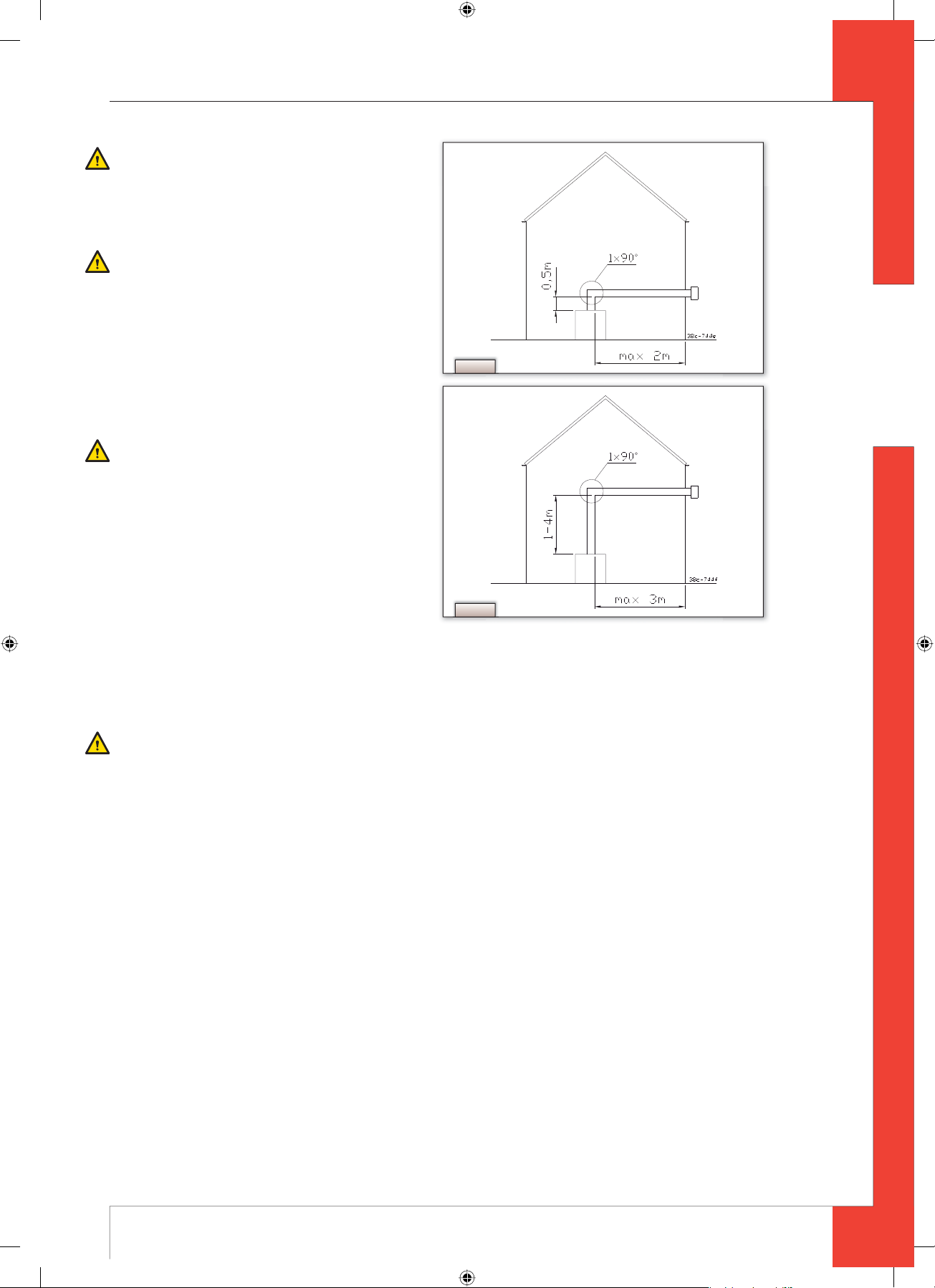
The settings of the equipment are made in the factory with a 1 to 4 meter vertical pipe + 90° pipe bend + wall duct.
In such case, the system does not require any further adjustments. If your situation is not as described above, you
should remove the air inlet guide as mentioned in 6.8.2.
Always start with a vertical pipe on the equipment. You may begin with a vertical pipe of at least 0.5 meter and a
maximum of 4 meters.
6
95900104UK Install_G20.indd 695900104UK Install_G20.indd 6 23-01-2009 09:17:2823-01-2009 09:17:28
M
ETRO 70 - INSTRUCTION FOR INSTALLATION
N.B.: Please note that if you install a 0.5 meters vertical
pipe on the equipment, the length should not exceed
2 meters.
The air inlet guide should be removed (see 6.8.2).
(See the example in
N.B.: Please note that if you install a 1 to max. 4 meters
vertical pipe on the equipment, the maximum ho-
rizontal length should not exceed 3 meters. The air
inlet guide should be removed (see 6.8.2) (see the
example in
Fig. 4a).
Fig. 4b)
6.5.2.2 Installing the concentric system
Fig. 4a
To install the concentric system commence as fol-
lows:
Construct the system from the (connection stub of
➠
the) appliance up
N.B. - Maintain a distance of at least 50 mm between the
outside of the concentric system and the walls and
/or ceiling. If the system will be built in (for instance) a cove, it should be fully made of in ammable
material;
- Use heat-resistant insulating material for ducts
made of combustible material.
Connect the concentric pipe sections and the
➠
bend(s);
Fit a clamping strip and silicone sealing ring to every
➠
connection;
Secure the clamping strip with a self-tapping screw in places which will be inaccessible after installation;
➠
Use enough brackets to ensure that the weight of the pipes does not rest on the appliance;
➠
Determine the remaining length of the wall duct;
➠
Cut the wall duct to size;
➠
Fit the wall duct with the bead//double edge at the top.
➠
!N.B. Be sure to maintain the correct insertion length.
N.B. Mount the wall duct onto a heat-resistant plate for use with a wall duct made of combustible material.
Fix the wall duct with four screws in the appropriate holes.
➠
!N.B. Fit the horizontal concentric pipe sections sloping towards the wall duct to stop rain getting in.
Fig. 4b
English
6.5.3 Use with a roof duct
6.5.3.1 Constructing the concentric system
A concentric pipe of at least one meter should fi rst be connected vertically to the equipment. The baffl e and/or air
inlet guides will be adjusted according to the structure of the concentric system.
You may proceed as follows:
1. Determine the number of pipe bends required (no distinction is made between 45° and 90° pipe bends).
2. Determine the horizontal pipe lengths in meters.
3. Determine the vertical/ sloping pipe lengths (without roof ducts) in meters.
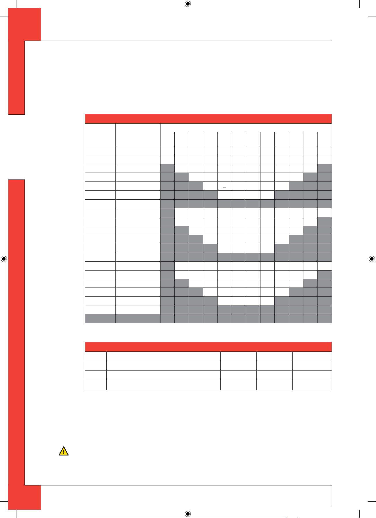
With this data, you can check using the Table 1, whether the drain system is permissible and the adjustments specifi c
to the same. The table functions as follows: in the fi rst 2 left columns, search for the number of the pipe bends and
the horizontal length and in the 3 column, search for the vertical/ sloping length, after which you will arrive at the
letter A, B or C. Thereafter, click in Table 2 to fi nd out the instructions relating to the air inlet guide and baffl e (for
installation / removal, see 6.8).
7
UK
95900104UK Install_G20.indd 795900104UK Install_G20.indd 7 23-01-2009 09:17:3023-01-2009 09:17:30
English
■
M
ETRO 70 - INSTRUCTION FOR INSTALLATION
The following are 2 examples:
Example 1 Example 2
1. 2 pipe bends 1. 3 pipe bends
2. 3 meters horizontal pipe 2. 4 meters horizontal pipe
3. 5 meters vertical /sloping pipe 3. 9 meters vertical /sloping pipe
Apply Situation A The situation is not permissible.
Table 1: Conditions for adjusting the equipment with roof ducts
G20 / G25 total number of
meters of horizon-
tal pipe lengths
no bends
0 BBBB
2 bends 0 A A B B
1 AAB
2 AA
3 A
3 bends
4 AABB
5
0 AABBBBB
1 AAABBBB
2 AAABBB
3 AAABB
4 AAAB
total number of meters of vertical and/or sloping pipe lengths
1234
5
B
B
B
B
678
CCC
BBC
BBB
BBB
ABBB
9
C
C
C
B
B
C
B
B
B
-
10 11 12
CCC
CCC
CC
C
CCC
CC
C
5
4 bends 0 A A A BBBBBCCC
1 AAAABBBBBC
2 AAAABBBB
3 AAAABB
4 AAAA
5
5 bends -
UK
■ = The situation is not permissible.
Table 2:
Situation G20/G25 Inlet guide Damper Distance damper
A DL = -6 - 1 metre + roof duct NO NO OPEN
B DL = 1 - 6 metre + roof duct YES YES 38 mm
C DL = 6 - 12 metre + roof duct YES YES 33 mm
6.5.3.2 Installing the concentric system
The roof duct can be used for either a sloping roof or a fl at roof.
Depending on the intended use, the roof duct will be supplied with either adhesive fl ashing for a fl at roof or a universally adjustable tile for a sloping roof.
Install the concentric system as follows:
Construct the system from the (connection stub of the) appliance up
➠
N.B. - Allow a minimum distance of 50 mm between the outside of the concentric system and the walls and/or ceiling.
- Use heat-resistant insulating material for ducts made of combustible material.
8
95900104UK Install_G20.indd 895900104UK Install_G20.indd 8 23-01-2009 09:17:3323-01-2009 09:17:33
 Loading...