

Dru Metro 130 Tunnel, Metro 130 Instructions For Installation Manual
English
Metro 130 - Metro 130 Tunnel
Please retain this document carefully
Instructions for installation (GB / IE)
G31 - propane
959.015.03.
uk
UK

2
Met ro 1 30 - i n s tr uc ti o n f or i n sta l lat i on
English
Contents
page
Foreword 2
1. Introduction 3
2. EC Declaration of Conformity 3
3. SAFETY 3
3.1 General 3
3.2 Regulations 3
3.3 Precautionary measures / safety instructions regarding installation 3
4. Instructions 4
5. Unpacking 4
6. Installation 4
6.1 Regulations 4
6.2 Gas type 4
6.3 Gas connection 4
6.4 Positioning the appliance 5
6.5. Flue gas discharge / combustion air supply system 6
6.6 Building the chimney breast 9
6.7 Installing the control box 10
6.8 Adjusting the appliance 10
6.9 Arranging the logs / pebbles 11
6.10 Glass window 15
7. Wireless remote control 16
7.1 Receiver 16
8. Final inspection 17
8.1 Gastightness 17
8.2 Gas pressure/pre-pressure 17
8.3 Igniting the pilot and main burner 17
8.4 Flame effect 18
9. Maintenance 18
10. Completion 19
11. Troubleshooting 20
Annex 1 Components supplied 23
Annex 2 Technical data 23
Annex 3 Spare parts 23
Foreword
As manufacturer of gas heating appliances, DRU develops and produces products to meet the highest possible
quality, performance and safety requirements.
As a result of which the user is able to enjoy using your appliance for years to come.
This appliance is CE marked; it complies with the essential requirements of the European Appliance Directive.
The appliance is supplied with two manuals: the installation manual and the user manual.
You the installer should be professionally skilled in the field of decorative gas heating.
The installation manual gives you all the information you will need to be able to install the appliance in such a way
that it works correctly and safely.
This manual deals with the installation of the appliance and the appropriate regulations. It also includes the technical data for the appliance and information on maintenance and troubleshooting.
Please read and use this installation manual carefully.
In the manuals the following symbols are used to denote important information:
➠
What to do
!Tip Suggestions and recommendations
!N.B. These instructions are important to avoid possible problems during installation and/or use.
N.B. These instructions are important to avoid re, personal injury or other serious damage.
Once you have completed the installation you are to hand both the user manual and this installation manual to the user.
UK
3
Me tr o 1 3 0 - i ns t ru ct io n f or i n sta l lat i on
English
1. Introduction
The appliance is available in two models, the Metro 130 and the Metro 130 Tunnel.
This version of the Metro 130 and the Metro 130 tunnel is suitable for use with propane. The safe operation of the
appliances is guaranteed by the use of a second thermocouple fitted to the main burner.
The Metro 130 is a ‘standard’ gas fire and should always be installed against a wall. The Metro 199 Tunnel is just that,
a ‘tunnel fire’ with both a front and back window.
The Metro 130 and the Metro 130 Tunnel are closed decorative fires. A closed tunnel draws its combustion air from
outside and not from the living area. This is done by way of a combined system that discharges the flue gases and supplies the combustion air. In this concentric system the outer pipe serves as air supply and the inner pipe as the flue.
This system can be installed through either the outer wall or the roof.
The appliances are built into a chimney breast. The DRU product range includes several chimney breasts.
The chimney breast must be well ventilated to ensure a good heat distribution. DRU can supply various ventilation
elements.
The appliances are supplied with a wireless, battery-operated remote control.
2. EC Declaration of Conformity
We hereby declare that the design and construction of the decorative gas heating appliance marketed by DRU conforms with the essential requirements of the Gas Appliance Directive.
This declaration will be rendered invalid should the appliance be altered in any way without the written consent of DRU.
Product: Decorative gas heating appliance
Type: Metro 130
Metro 130 Tunnel
Applicable EC Directives: 90/396/EEC
Applicable harmonised standards: NEN-EN-613, NEN-EN-613/A1
In-house measures guarantee that serially produced appliances always conform with the essential requirements of
the current EC Directives and the applicable standards.
R. Gelten
DRU VERWARMING B.V.
Postbus 1021, 6920 BA Duiven
Ratio 8, 6921 RW Duiven
www.dru.nl
3. SAFETY
3.1 General
N.B. - Please read this chapter on safety carefully before commencing installation or maintenance;
- Always observe universal regulations and the precautionary measures / safety instructions in this manual.
3.2 Regulations
The appliance should be installed in compliance with current national, local and constructional (installation) regulations.
3.3 Precautionary measures / safety instructions regarding installation
Observe the following precautions / safety regulations precisely:
➠
You may only install and/or service this appliance if your are a qualied installer skilled in installing decorative gas res;
➠
do not adjust the appliance in any way;
➠
use incombustible and heat-resistant materials for building a chimney breast, including the back wall, the inside and
the top of the chimney breast;
➠
the minimum internal dimensions required for the chimney breast must be taken into account;
➠
the chimney breast should be ventilated by vents with total free vent area of 200 cm2;
➠
only use the ue /combustion air supply systems supplied by DRU;
➠
use the wall brackets supplied to mount the appliance;
➠
do not install the appliance at against the back wall;
➠
leave the space between the feet free;
➠
do not cover and/or pack the appliance with an insulating blanket or any other material;
➠
make sure combustible objects and / or materials have a minimum distance from the appliance of 500 mm;
➠
only use the log/pebble set supplied;
➠
arrange the logs/pebbles exactly as described;
➠
leave a space around the pilot burner;
UK
4
Me tr o 1 3 0 - i ns t ru ct io n f or i n sta l lat i on
English
➠
avoid any dirt in the gas pipes and connections;
➠
test the gastightness of all connections before use;
➠
use heat-resistant electrical connection materials;
➠
install the electrical connections away from the appliance;
➠
replace torn or broken panes;
➠
avoid blocking the explosion hatch/hatches;
➠
ensure the explosion hatch/hatches on top of the heater are right on their seats, before you close the chimney breast;
➠
do not ignite the appliance until installation has been completed.
4. Instructions
To ensure the appliance works correctly and safely, always take the following points into consideration during installation:
➠
place the control box supplied as low as possible;
➠
ensure the ignition wire does not lie across the receiver;
➠
ensure the ignition wire does not touch or cross the aerial;
➠
to avoid weakening the spark ensure the ignition wire does not touch anything metal;
➠
if the appliance is to be built in ush with the wall, nish the edges neatly;
➠
do not plaster over the anges;
➠
avoid damaging the glass when removing/tting the window pane;
➠
to prevent dirt burning into the glass, make sure it is clean before use.
5. Unpacking
Please take the following points into consideration when unpacking the appliance:
➠
Check the appliance for transit damage;
➠
Contact DRU Service if necessary.
Once the packaging material has been removed, you should have the following components:
- Socket spanner: You will find this in the space between the assembly frame and the combustion chamber;
- Trimmings: These are in the same space.
Once you have removed the glass pane you can remove the box of components from the combustion chamber.
!N.B. Be careful not to damage the glass when removing/tting the window pane.
➠
Remove the window as described in paragraph 6.10.1;
➠
Take the box of components out of the combustion chamber.
Annex 1 / Table 4 specifies the components you should have once everything has been unpacked.
➠
Contact DRU Service if after unpacking the appliance you do not have all the components;
➠
Dispose of the packaging in an appropriate manner.
6. Installation
Please read the manual carefully to ensure that once installed the appliance will work correctly and safely.
!N.B. Install the appliance in the order described in this chapter.
6.1 Regulations
- Observe the current applicable (installation) regulations;
- Observe the regulations/instructions laid down in this manual.
6.2 Gas type
The type plate specifies the type of gas, gas pressure, and the country this appliance is intended for. The type plate
is on a chain and that is where it should stay.
N.B. Check that the appliance is suitable for the local gas type and pressure.
6.3 Gas connection
The gas connection should have a gas tap located near the appliance.
N.B. Prevent any dirt getting into the gas pipes or connections.
The following requirements apply for the gas connection:
➠
the size of the gas pipe should be such that no pressure loss can occur;
➠
the gas tap must be CE marked;
➠
the gas tap should be accessible at all times;
➠
Do not twist the gas tap when connecting the gas pipe.
UK

5
Me tr o 1 3 0 - i ns t ru ct io n f or i n sta l lat i on
English
6.4 Positioning the appliance
Position the fire as follows:
N.B. - Make sure combustible objects and / or materials have a minimum distance from the appliance of 500 mm;
- Do not adjust the appliance in any way.
➠
Determine the position of the appliance;
➠
Create a gas connection in the appropriate position; see section 0 for details;
➠
Create a duct for the ue / combustion air supply system, with the diameter shown below; see section 6.5 for details;
➠
Ø160 mm for a wall duct of incombustible material;
➠
Ø 250 mm for a wall duct of combustible material;
➠
Ø160 mm for a roof duct of incombustible material;
➠
Ø 250 mm for a roof duct of combustible material.
!N.B. - Allow for the depth of the appliance (see
Fig. 2)
(Metro 130: minimum of 410 mm; Metro 130 Tunnel: minimum of 450 mm);
- Allow for the build-in height; this will depend on the height of the adjustable feet (see
Fig. 1).
➠
Move the appliance into its intended position.
The gas control block is mounted onto the burner plate at the bottom of the appliance. This should be removed and
placed in the control box later. See section 6.7 for information on how to fit the gas control block.
Commence as follows:
➠
Disconnect the hoses from the gas control block (exible gas hose, aluminium pilot pipe and thermocouple 1);
!N.B. The red wire of thermocouple 2 must not be disconnected from the gas control block.
Photo 1a shows how the wires
are attached to the thermocouple.
➠
Unscrew the self-tapping screw in the burner plate and remove the gas control block.
➠
Carefully unwind the red and black wires of thermocouple 2.
➠
Lay the gas control block together with the wires of thermocouple 2 towards the control box.
N.B. - Avoid dirt in the hoses;
- Avoid kinks in the hoses.
Metro 130
Metro 130 tunnel
min 1020
max 1070
1316
1498
1316
1544515
380
min 220
max 270s
164
38c-1212
50
min 1020
max 1070
1498
1316
min 220
max 270
380
16415
398
38c-1211
50
Front view
Top view
Side view
Front view
Side view
Top view
Fig. 1
max 100 mm
1320
384
=
x
=
38c-1225
A
A
b
c
A-A
min 1610 mm inside
min 410 metro 130 inside
min 450 mm metro 130 tunnel inside
min
1710 mm
inside
Total
ventilation
200 cm
2
Maximal
plaster line
Maximale
plaster line
Control box
Fig. 2
UK
6
Me tr o 1 3 0 - i ns t ru ct io n f or i n sta l lat i on
English
➠
Unroll the hoses towards the control box;
➠
Unroll the ignition wire towards the control box.
!N.B. The type plate should be connected to the chain.
➠
Lay the chain with the type plate facing the control box;
➠
Adjust the height of the appliance;
➠
Using a spirit level to ensure it is absolutely level.
N.B. - Do not install the appliance at against the back wall;
- Leave the space between the feet free;
- Do not cover and/or pack the appliance with an insulating blanket or any other material.
➠
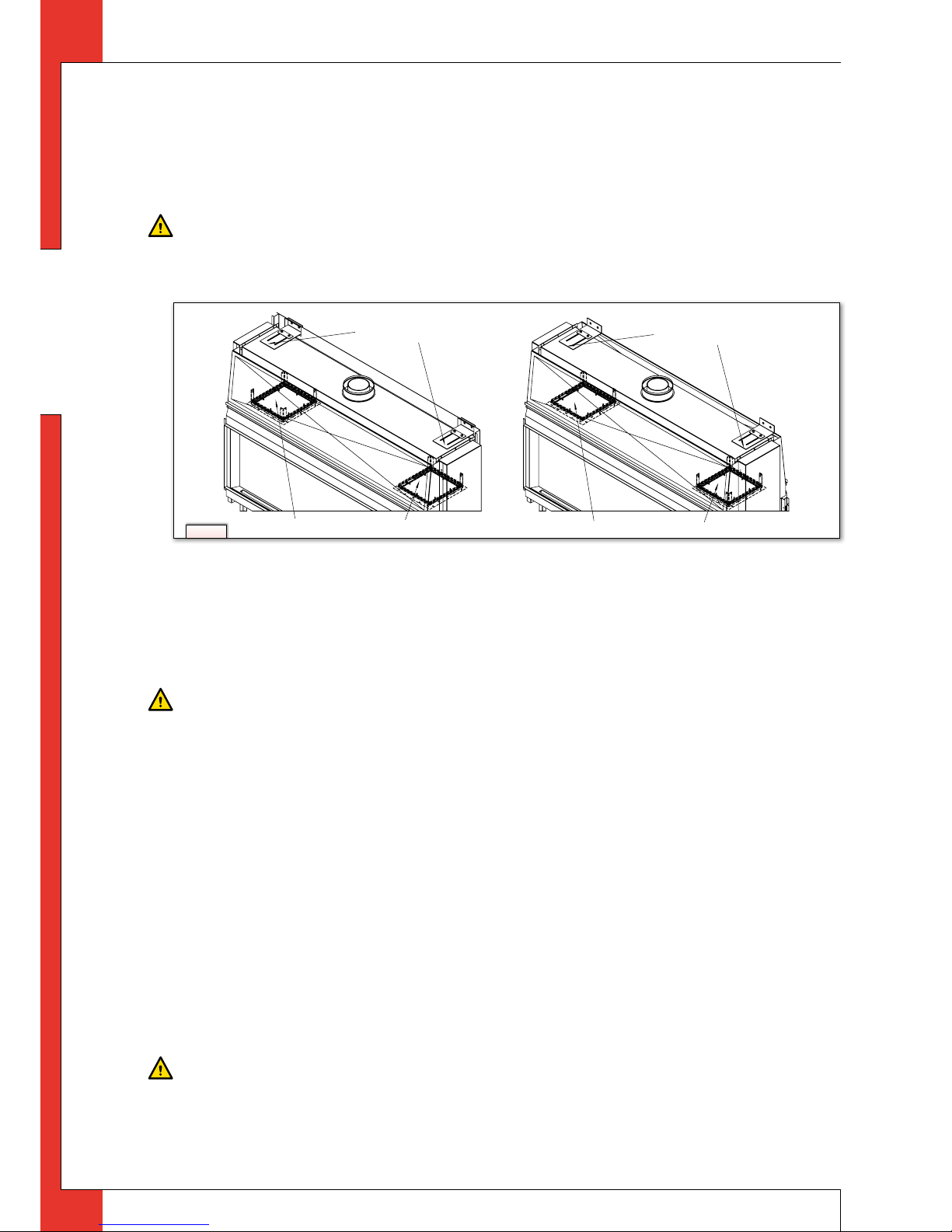
Secure the appliance against the wall using the wall brackets and rawplugs supplied (see Fig. 3).
6.5. Flue gas discharge / combustion air supply system
6.5.1 General
The appliance is of the C11/C31 type.
The appliance is connected to a combined flue gas discharge/combustion air supply system, hereafter referred to
as the concentric system.
The passage to the outside can be made with a wall duct (see section 6.5.2) or with a roof duct (see section 6.5.3).
If necessary, you can also use an existing discharge channel (see section 6.5.4).
N.B. - Only use the concentric system supplied by DRU (Ø100 / Ø150 mm). This system was tested in combination with the
appliance; DRU cannot guarantee a proper and safe operation of other systems and cannot accept liability for these
systems;
- For connecting to an existing chimney ue you should only use the installation set supplied by DRU.
The concentric system is constructed from (the discharge stump of) the appliance.
If structural circumstances require that the concentric system is placed first, the appliance can later be connected
with a telescopic pipe piece.
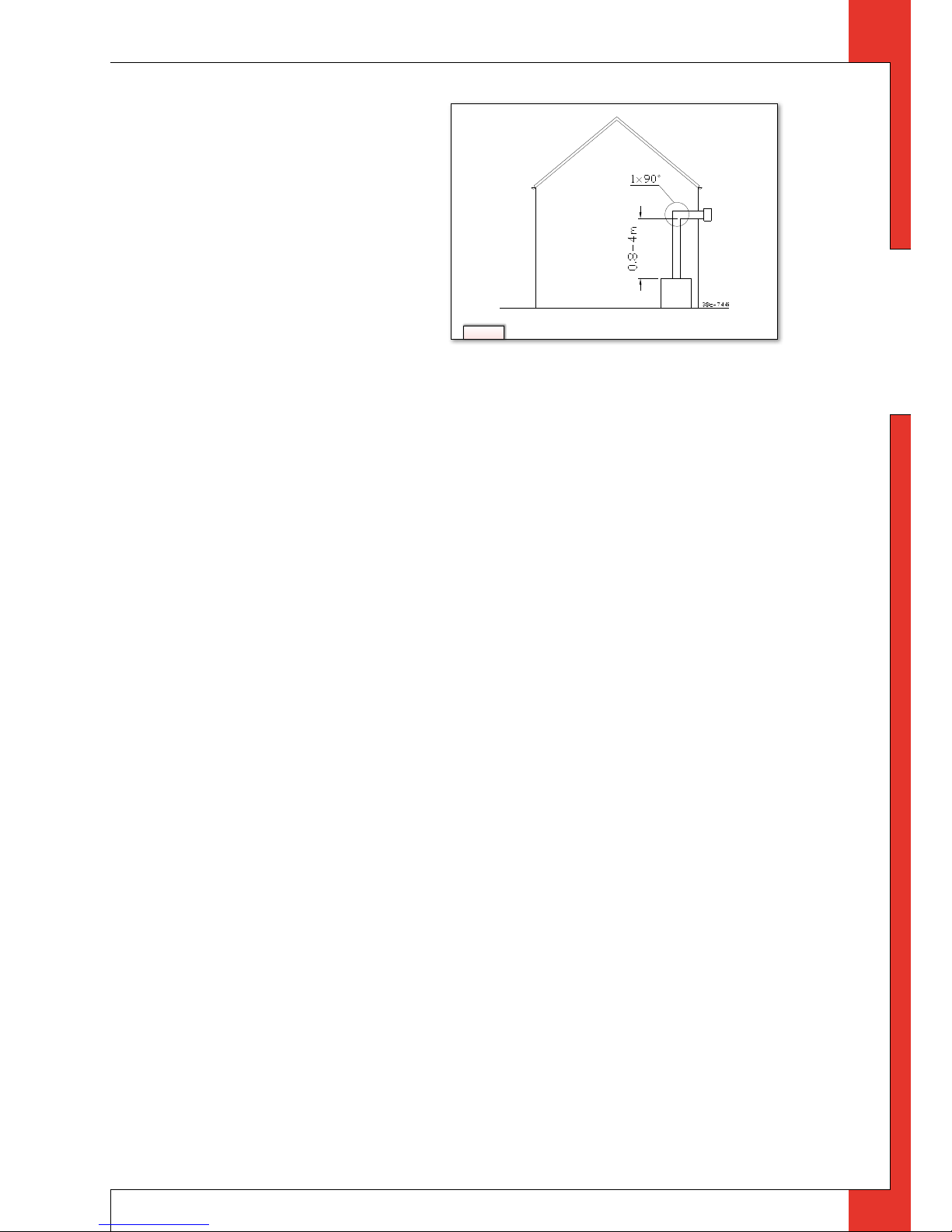
6.5.2 Application with wall duct
6.5.2.1 Construction of concentric system with wall duct
The concentric system with wall duct has to comply with the following conditions (see Fig. 4):
- First, a concentric pipe of at least 0.8 meters should be connected vertically to the appliance;
- The total vertical pipe length may have a maximum of 4 meters;
- A 90° bend is connected to the end of the vertical part;
- The wall duct is connected directly to the 90° bend (i.e. no horizontal part).
When using this configuration you must remove the air inlet guides (see Section 6.8, Adjusting the appliance); the
baffle is not fitted.
6.5.2.2 Installing the concentric system
To install the concentric system commence as follows:
➠
Construct the system from the (connection stub of the) appliance up.
N.B. - Maintain a distance of at least 50 mm between the outside of the concentric system and the walls and /or ceiling. If
the system will be built in (for instance) a cove, it should be fully made of incombustible material;
- Use heat-resistant insulating material for ducts made of combustible material;
- The rosette (mounting inner plate) of the wall duct is too small to seal the Ø 250 mm opening when passing through
combustible material. That is why you should rst apply a suciently large heat-resistant intermediate plate to the
wall. Then, the rosette is mounted on the intermediate plate.
38c-1223
38c-1226
Wall brackets
Explosion by-pass valves
Wall brackets
Explosion by-pass valves
Metro 130
Metro 130 tunnel
Fig. 3
UK
7
Me tr o 1 3 0 - i ns t ru ct io n f or i n sta l lat i on
English
➠
Connect the concentric pipe sections and the bend(s);
➠
Fit a clamping strip and silicone sealing ring to every
connection;
➠
Secure the clamping strip with a self-tapping screw in
places which will be inaccessible after installation;
➠
Use enough brackets to ensure that the weight of the
pipes does not rest on the appliance;
➠
Determine the remaining length of the wall duct;
➠
Cut the wall duct to size;
!N.B. - Make sure that the right insertion length is main-
tained;
- Place the wall duct with the groove/folded seam at
the top;
- Make sure the horizontal concentric pipe pieces are
sloping towards the wall duct, in order to prevent rain water from entering.
➠
Mount the rosette (mounting inner plate); if necessary, on a heat resistant intermediate plate when passing through
combustible material;
➠
Attach the wall duct from the outside with four screws in their respective holes.
!N.B. Some heat-resistant isolation materials contain volatile components that will spread an unpleasant smell for a pro-
longed time; these are not suitable.
6.5.3 Application with roof duct
6.5.3.1 Construction of concentric system with roof duct
The concentric system with roof duct has to comply with the following conditions
➠
The construction of the chosen system has to be allowed. (See the procedure described below);
➠
First, a concentric pipe of at least 1 meter should be connected vertically to the appliance.
Depending on the construction of the concentric system, the appliance is set by placing the baffle and/or removing
the air inlet guides.
In the following procedure you can see how the allowability of a concentric system can be determined and which
settings are needed.
➠
Determine the following data:
1. The number of bends required (no distinction is made between 45° and 90° bends);
2. The total number of meters of horizontal pipe length;
3. The total number of meters of vertical and/or sloping pipe length (wall duct not included).
With these data and Table 1 you will be able to determine whether the concentric system is allowed.
In Table 2 you can see which setting the appliance needs.
Follow the procedure described below:
➠
In the rst 2 columns of Table 1, look for the number of bends required and the total horizontal pipe length;
➠
In the 3rd column of Table 1, look for the total vertical and/or sloping pipe length.
If you end up in a box with the letter A, B, or C, the concentric system chosen by you is allowed.
➠
Use Table 2 to determine which conditions apply for the bae and/or the air inlet guides (for setting see section 6.8);
Fig. 4
UK

8
Me tr o 1 3 0 - i ns t ru ct io n f or i n sta l lat i on
English
Examples
To clarify, we will give 2 examples to determine the allowability of a concentric system and the conditions for setting
the appliance.
In Table 1 the route to be followed is indicated by arrows. The result is indicated by a box with a red border.
Example 1
1) 2 bends
2) 3 meters horizontal
3) 8 meters vertical/sloping
→ Construction of this concentric system is allowed.
→ Situation B applies for setting the appliance
Example 2
1) 3 bends
2) 4 meters horizontal
3) 10 meters vertical/sloping
→ Construction of this concentric system is not allowed.
Table 1: Determination of the permissibility of a concentric system with a roof duct
G31 Total number of
meters horizontal
pipe length
Total number of meters vertical and/or inclined pipe length
1 2 3 4 5 6 7
Q8
9
Q10
11 12
no bends 0 B B B B B C C C C C C C
2 bends 0 A A B B B B B C C C C C
1 A A B B B B B C C C
2 A A B B B B B C
→
3 A A B B B B
4 A A B B
5
3 bends 0 A A B B B B B C C C C
1 A A B B B B B C C
2 A A B B B B B
3 A A B B B
→
4 A A B
5
4 bends 0 A A B B B B B C C C
1 A A B B B B B C
2 A A B B B B
3 A A B B
4 A A
5
5 bends -
n = situation is not allowed
Table 2: Conditions for the adjustment of the appliance with a roof duct
G31
Situation Air inlet guides Baffle Distance of restriction in mm
A NO NO OPEN
B NO YES 56
C YES YES 47
UK
 Loading...