

Dru Metro 100 XT-3, Metro 100 XT-2 G20, Metro 100 XT-2 G25, Metro 100 XTL, Metro 100 XT-3 G20 Installation Manual
...
EnglishDeutsch
Store this document in a safe place
Dieses Dokument bitte sorgfältig aufbewahren
Metro 100 XT-3
Installation manual (GB / IE)
Installationsanleitung (DE / AT / BE / CH)
959.019.01.ML1
G20/25
95901901_ML1 Install.indd 195901901_ML1 Install.indd 1 16-9-10 8:3216-9-10 8:32

2
METRO 100 XT3 INSTALLATION MANUAL
English
Contents
page
Preface 3
1. Introduction 3
2. CE declaration 3
3. SAFETY 4
3.1 General 4
3.2 Regulations 4
3.3 Precautions / safety instructions during installation 4
4. Instructions 4
5. Removing the packaging 4
6. Installation 5
6.1 Regulations 5
6.2 Type of gas 5
6.3 Gas connection 5
6.4 Placing the appliance 5
6.5 Flue gas discharge / combustion air supply system 6
6.6 Placing the chimney breast 10
6.7 Placing the control box 11
6.8 Adjusting the appliance 12
6.9 Placing the wood/pebble set 12
6.10 Panes 13
7. Wireless remote control 14
7.1 Receiver 14
8. Final check 15
8.1 Gastightness 15
8.2 Gas pressure / pre-pressure 15
8.3 Ignition pilot and main burner 15
8.4 Flame image 16
9. Maintenance 17
9.1 Parts 17
10. Delivery 17
11. Malfunctions 18
Appendix 1 Parts included with the delivery 21
Appendix 2 Technical data 21
Appendix 3 Figures 42
GB
95901901_ML1 Install.indd 295901901_ML1 Install.indd 2 16-9-10 8:3216-9-10 8:32
3
METRO 100 XT3 INSTALLATION MANUAL
English
Preface
DRU, a manufacturer of gas- red heating appliances, develops and produces products that comply with the highest
quality, performance and safety requirements.
This guarantees that the user will be able to enjoy using his product for many years to come.
This appliance has a CE marking, which means that it complies with the essential requirements of the European gas
appliance directive.
Two manuals are supplied with the appliance: the installation manual and the user manual.
As an installer, you must be competent in the eld of atmospheric gas- red heating.
The installation manual will give you the information you need to install the appliance in such a way that it will
operate properly and safely.
This manual discusses the installation of the appliance and the regulations that apply to the installation. In addition,
you will nd technical data for the appliance and information on maintenance, any malfunctions that might occur
and their possible causes.
The gures are included at the back of this booklet (Appendix 3).
Please carefully read and use this installation manual.
The following symbols are used in the manual to indicate important information:
➠
Work to be performed
!Tip
Suggestions and recommendations
!Caution
You will need these instructions to prevent problems that might occur during installation and/or use.
Caution
You need these instructions to prevent re, personal injury or other serious damages.
Af ter delivery, you should give the user manual and this installation manual to the user.
1. Introduction
The Metro 100 XT-3 is a room-sealed atmospheric gas- red heating appliance.
This version of the Metro 100 XT-3 is suitable for natural gas. The safe operation of the appliance is guaranteed by
the use of a second thermocouple tted to the main burner.
A room-sealed appliance does not extract the combustion air from the living environment, but from outside. This is
done by means of a combined ue gas discharge system / combustion air supply system. In this concentric system,
the outer pipe functions as the air supply and the inner pipe functions as the ue gas discharge.
This system can be installed through the wall or through the roof.
These appliances are built within a chimney breast. For this, DRU has a number of chimney breasts in its range.
In order to reach a proper heat discharge, the chimney breast must be ventilated. DRU is able to supply various
ventilation elements.
The adjustable height of the appliance can be increased by means of the extension legs that can be ordered from
DRU.
The appliances are supplied with a wireless remote control that works on batteries.
2. CE declaration
We hereby declare that the design and construction of DRU’s atmospheric gas- red heating appliance comply with
the essential requirements of the Gas Appliance Directive.
Product: atmospheric gas- red heating appliance
Type: Metro 100 XT-3
Applicable EEC directives: 90/396/EEC
Applied harmonized standards: NEN-EN-613
NEN-EN-613/A1
Internal measures by the company guarantee that appliances produced in series comply with the essential requirements of the prevailing EEC directives and the standards derived from them.
This declaration will lose its validity if adjustments are made to the appliance, without prior written permission by DRU.
M.J.M. Gelten
General manager
DRU verwarming B.V.
Postbus 1021, 6920 BA Duiven
Ratio 8, 6921 RW Duiven
www.dru.nl
GB
95901901_ML1 Install.indd 395901901_ML1 Install.indd 3 16-9-10 8:3216-9-10 8:32

4
METRO 100 XT3 INSTALLATION MANUAL
English
3. SAFETY
3.1 General
Caution
- Carefully read this chapter on safety, before you start performing installation or maintenance work;
- Pl ease observe the general regulations and the precautions/safety instructions in this manual.
3.2 Regulations
Please install the appliance in accordance with the applicable national, local and constructional (installation) regulations.
3.3 Precautions / safety instructions during installation
Carefully observe the following precautions/safety regulations:
➠
you should only install and maintain the appliance if you are a competent installer in the eld of atmospheric gas- red heating;
➠
do not make any changes to the appliance;
➠
use non combustible and heat-resistant materials for the chimney breast, including the top of the chimney breast, the
material in the chimney breast and the back wall against which the appliance will be placed;
➠
take su cient measures to prevent temperatures of a wall behind the chimney breast becoming too high, including
the materials and/or objects behind the wall;
➠
comply with the minimum required internal measurements of the chimney breast;
➠
ventilate the chimney breast by means of the ventilation holes, which will form a combined passage of at least 200cm2;
➠
only use the ue gas discharge / combustion air supply system supplied by DRU;
➠
mount the appliance using the wall brackets supplied;
➠
do not place the appliance too tightly against the back wall;
➠
make sure the space between the appliance’s legs is kept free;
➠
do not cover the appliance and/or do not wrap it in an insulation blanket or any other material;
➠
make sure that combustible objects and/or materials have a distance from the appliance of at least 500mm;
➠
only ever use the supplied wood/pebble set;
➠
place the wood/pebble set exactly as described;
➠
make sure the pilot burner and the space around it is kept free;
➠
make sure thermocouple 2 and the space around it are kept free;
➠
make sure there is no dirt in gas pipes and connections;
➠
mount a gas tap directly next to the appliance;
➠
check the connections for gastightness before using the appliance;
➠
use heat resistant electrical wiring;
➠
place the electrical wiring in such a way that they are free from the appliance;
➠
replace torn or broken panes;
➠
avoid blocking of the pressure equalization hatch(es) on top of the appliance;
➠
check whether the pressure equalization hatch(es) t well onto the sealing surface, prior to building in the appliance;
➠
do not ignite the appliance until it is fully installed.
4. Instructions
Observe the following items during installation in order to guarantee a proper and safe operation of the appliance:
➠
mount the control box supplied as low as possible;
➠
avoid that the ignition cable runs over the receiver;
➠
avoid that the ignition cable touches or crosses the antenna;
➠
avoid that the ignition cable runs alongside metal parts, in order to prevent weakening of the spark;
➠
properly nish the edges in case of a tight construction;
➠
do not apply plaster on or over the anges;
➠
avoid damaging the pane when removing/placing the glass window;
➠
clean the pane before you use the appliance, in order to prevent dirt from burning in the glass;
➠
make sure that the wires of thermocouple 2 cannot come into contact with hot parts.
5. Removing the packaging
Note the following items when removing the packaging:
➠
Check the appliance for damages during transport.
➠
If necessary, contact DRU Service.
After removing the packaging, you should have the following components:
- Socket spanner; you will nd it in the space between the assembly frame and the combustion chamber;
- Decorative strips; you will nd them in the abovementioned space as well;
- Front pane; you will nd it in the same box as the appliance - provided with protective corners;
GB
95901901_ML1 Install.indd 495901901_ML1 Install.indd 4 16-9-10 8:3216-9-10 8:32
5
METRO 100 XT3 INSTALLATION MANUAL
English
- Box containing parts; you will nd it in the combustion chamber.
!Caution
Avoid damaging the front pane when removing it from the packaging.
➠
Remove the box containing parts from the combustion chamber.
In appendix 1 / table 5 you can see which parts you should have after removing the packaging.
➠
Contact DRU Service if you do not have all the parts after you nished removing the packaging.
➠
Dispose packaging in accordance with local regulations.
6. Installation
Read this manual carefully to ensure a proper and safe operation of the appliance.
!Caution
Install the appliance in the order described in this chapter.
6.1 Regulations
➠
Observe the applicable (installation) regulations.
➠
Observe the regulations/instructions in this manual.
6.2 Type of gas
The data plate indicates for which type of gas, gas pressure and for which country this appliance is intended. The
data plate is connected to a chain. It should remain connected to the chain.
Caution
Check whether the appliance is suitable for the type of gas and the gas pressure used at the location.
6.3 Gas connection
Place a gas tap in the gas connection, close to the appliance.
Caution
- Make sure there is no dirt in gas pipes and connections;
- Prevent twisting the gas tap when connecting the gas pipe.
The following requirements apply to the gas connection:
- use a gas pipe with the correct dimensions, so that no pressure loss can occur;
- the gas tap should have the CE marking;
- you should always be able to reach the gas tap.
6.4 Placing the appliance
Caution
- Make sure that combustible objects and/or materials have a distance from the appliance of at least 500mm;
- Always place the appliance against a wall of non combustible and heat-resistant material;
- Take su cient measures to prevent temperatures of a wall behind the chimney breast becoming too high, including
the materials and/or objects behind the wall;
- Do not make any changes to the appliance.
!Caution
- Take the adjustable height of the appliance into account; it depends on the setting of the adjustable feet (see g.1);
- If applicable, the extension legs should be xed by means of self-tapping screws;
- Take the minimum internal depth of the appliance into account; Metro 100 XT-3: 454 mm (see g. 3a and g. 3b.
Fig.3b shows a chimney breast made of stone-like materials).
!Tip
You can determine the construction height of the appliance (X in g. 3a and g. 3b) yourself.
Place the appliance as follows:
➠
Determine the location of the appliance.
➠
Determine the construction height of the appliance.
➠
Provide a gas connection at the location. For details, see section 6.3.
➠
Make a passage for the ue gas discharge/combustion air supply system with the following diameters. For details, see
section 6.5.
- Ø160 mm for a wall terminal through non combustible material;
- Ø 250 mm for a wall terminal through combustible material;
- Ø160 mm for a roof terminal through non combustible material;
- Ø 250 mm for a roof terminal through combustible material.
GB
95901901_ML1 Install.indd 595901901_ML1 Install.indd 5 16-9-10 8:3216-9-10 8:32
6
METRO 100 XT3 INSTALLATION MANUAL
English
➠
Place the appliance on its destined location.
The gas control is mounted under the appliance, at the burner plate. It should be disconnected and placed in the
control box at a later stage. For placing the gas control in the control box, see section 6.7.
Follow the procedure described below:
➠
Disconnect the pipes from the gas control ( exible gas pipe, aluminium pilot- ame pipe and thermocouple 1).
!Caution
The red wire of thermocouple 2 must remain connected to the gas control. Fig. 4 shows how the wires are connected
to the thermocouple.
➠
Disconnect the gas control from the burner plate by unscrewing the self-tapping screw.
➠
Carefully unwind the red and black wires of thermocouple 2.
➠
Lay the gas control together with the wires of thermocouple 2 in the direction of the control box.
Caution
- Make sure there is no dirt in gas pipes and connections;
- Avoid kinks in the pipes.
➠
Roll out the pipes in the direction of the control box.
➠
Roll out the ignition cable in the direction of the control box.
!Caution
The data plate should remain connected to the chain.
➠
Place the chain with the data plate in the direction of the control box.
➠
Set the height of the appliance using the adjustable feet and
➠
Make the appliance level at the same time.
Caution
- Do not place the appliance too tightly against the back wall; this is guaranteed by means of the wall brackets;
- Make sure the space between the appliance’s legs is kept free;
- Do not cover the appliance and/or do not wrap it in an insulation blanket or any other material.
➠
Connect the appliance to the wall using wall brackets (B) and the key bolts supplied; see g. 2.
6.5 Flue gas discharge / combustion air supply system
6.5.1 General
The appliance is of the C11/C31 type.
The appliance is connected to a combined ue gas discharge/combustion air supply system, hereafter referred to
as the concentric system.
The passage to the outside can be made with a wall terminal (see section 6.5.2) or a roof terminal (see section 6.5.3).
If necessary, you can also use an existing chimney (see section 6.5.4).
Caution
- Only use the concentric system supplied by DRU (Ø100 / Ø150mm). This system has been tested together with the appliance. DRU cannot guarantee a proper and safe operation of other systems and does not accept any liability for this;
- For connecting to an existing chimney you should only use the chimney kit supplied by DRU.
The concentric system is constructed from (the connection stump of) the appliance.
If structural circumstanc es require that the concentric system is placed rst, the appliance can later be connected
with a telescopic pipe piece.
GB
95901901_ML1 Install.indd 695901901_ML1 Install.indd 6 16-9-10 8:3216-9-10 8:32
7
METRO 100 XT3 INSTALLATION MANUAL
English
6.5.2 Application with wa ll terminal
6.5.2.1 Construction of concentric system with wall terminal
The concentric system with wall terminal has to comply with the following conditions:
- First, a concentric pipe of at least 0.5 meters should be connected vertically to the appliance;
- The total vertical pipe length may have a maximum of 4 meters;
- A 90° bend is connected to the other end of the vertical part;
- When using 0.5 meter of vertical pipe length, the total horizontal pipe length can have a maximum of 2 meters
(excluding wall terminal, see g. 5a);
- When using a minimum of 1 meter up to a maximum of 4 meters of vertical pipe length, the total horizontal pipe
length can have a maximum of 3 meters (excluding wall terminal, see g. 5b and 5c).
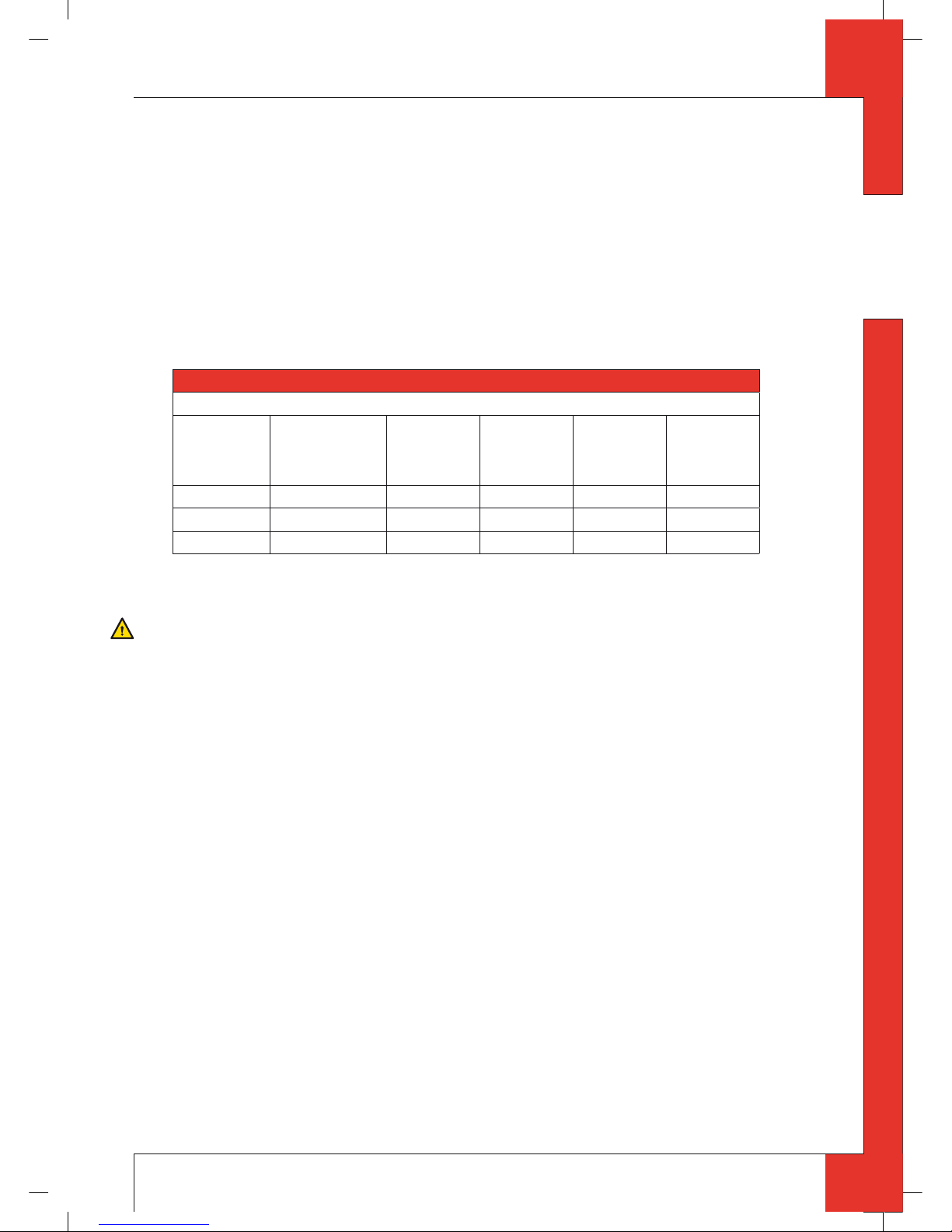
Depending on the construction of the concentric system, the appliance must receive further settings; see Table 1 for
determining the conditions and section 6.8, Adjusting the appliance, for the method.
Table 1: Conditions for the adjustmen t of the appliance with a wall terminal
G20/25
Total number of
meters vertical
pipe length
Total number of
meters horizontal
pipe length (excluding
wall terminal)
See gure Air inlet guide Ba e Distance of
restriction
in mm
0,5 0 - 2 5a
NO NO OPEN
1 - 4 >0 - 3 5b
NO NO OPEN
1 - 4 0* 5c
YES NO OPEN
* factory setting
6.5.2.2 P lacing concentric system with wall terminal
Caution
- Maintain a distance of at least 50mm between the outside of the concentric system and the walls and/or the ceiling.
If the system is built in (for instance) a cove, it should be made with non combustible material all around it.
- Use heat-resistant insulation material when passing through combustible material;
- The rosette (mounting inner plate) of the wall terminal is too small to seal the Ø250mm opening when passing
through combustible material. That is why you should rst apply a su ciently large heat-resistant intermediate
plate to the wall. Then, the rosette is mounted on the intermediate plate.
!Caution
Some heat-resistant insulation materials contain volatile components that will spread an unpleasant smell for a pro-
longed time; these are not suitable.
Place the concentric system as follows:
➠
Build the system up from (the connection stump of ) the appliance.
➠
Connect the concentric pipe pieces and the bend.
➠
On each connection, apply a clip binding with silicon sealing ring.
➠
Use a self-tapping screw to x the clip binding to the pipe on locations that cannot be reached after installation.
➠
Apply su cient clamps, so that the weight of the pipes does not rest on the appliance.
➠
Determine the remaining length of the wall terminal;
➠
Make sure the wall terminal has the right dimensions.
!Caution
- Make sure that the right insertion length is maintained;
- Place the wall terminal with the groove/folded seam at the top;
- Make sure the horizontal concentric pipe pieces are sloping towards the wall terminal, in order to prevent rain water
from entering.
➠
Mount the rosette (mounting inner plate); if necessary, on a heat resistant intermediate plate when passing through
combustible material.
➠
Attach the wa ll terminal from the outside with four screws in their respective holes.
GB
95901901_ML1 Install.indd 795901901_ML1 Install.indd 7 16-9-10 8:3216-9-10 8:32

8
METRO 100 XT3 INSTALLATION MANUAL
English
6.5.3 Applica tion with roof terminal
6.5.3.1 Construction of concentric system with roof terminal
The concentric system with roof terminal has to comply with the following conditions:
- The construction of the chosen system has to be allowed. (See the procedure described below);
- First, a concentric pipe of at least 1meter should be connected vertically to the appliance.
Depending on the construction of the concentric system, the appliance is set by placing the ba e and/or removing
the air inlet guide.
In the following procedure you can see how the allowability of a concentric system can be determined and which
settings are needed.
➠
Determine the following data:
1) The number of bends required (no distinction is made between 45° and 90° bends);
2) The total number of meters of horizontal pipe length;
3) The total number of meters of vertical and/or sloping pipe length (roof terminal excluded).
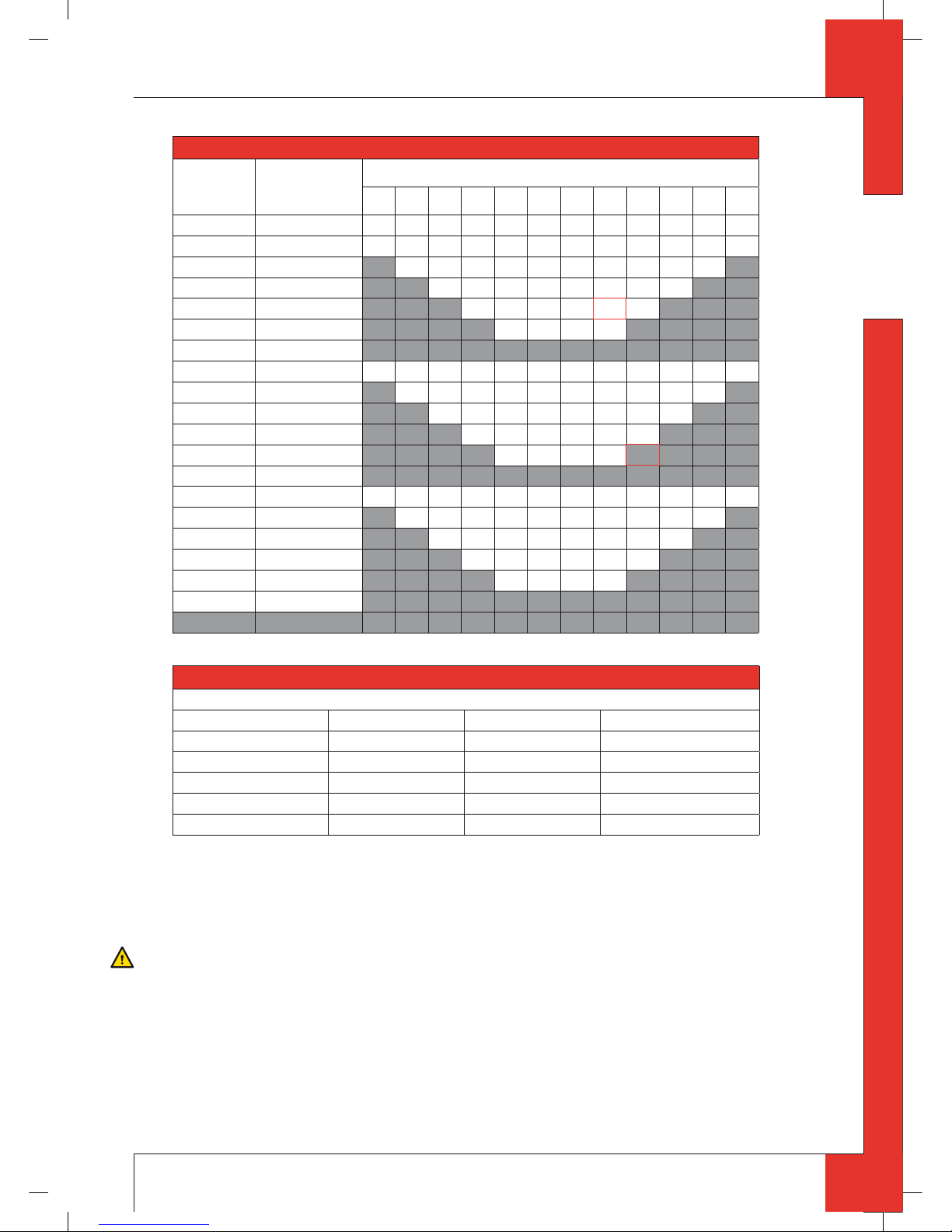
With these data and Table2 you will be able to determine whether the concentric system is allowed.
In Table3 you can see which setting the appliance requires.
Follow the procedure described below:
➠
In the rst 2 columns of Table2, look for the number of bends required and the total horizontal pipe length.
➠
In the 3rd column of Table2, look for the total vertical and/or sloping pipe length.
If you end up in a box with the letter A, B, C, D or E, the concentric system chosen by you is allowed.
➠
Use Table 3 to determine which conditions apply for the ba e and/or the air inlet guide (for setting, see section 6.8).
Examples
To clarify, we will give 2 examples to determine the allowability of a concentric system and the conditions for setting
the appliance.
In Table 2 the route to be followed is indicated by arrows. The result is indicated by a box with a red border.
Example 1
1) 2 bends
2) 3 meters horizontal
3) 8 meters vertical/sloping
→ Construction of this concentric system is allowed.
→ Situation B applies for the adjustment of the appliance.
Example 2
1) 3 bends
2) 4 meters horizontal
3) 9 meters vertical/sloping
→ Construction of this concentric system is not allowed.
GB
95901901_ML1 Install.indd 895901901_ML1 Install.indd 8 16-9-10 8:3216-9-10 8:32
9
METRO 100 XT3 INSTALLATION MANUAL
English
Table 2: Determination of th e permissibility of a concentric system with a roof terminal
G20/25 Total number of
meters horizontal
pipe length
Total number of meters vertical and/or sloping pipe length
1234567
↓8 ↓9
10 11 12
no bends 0 B B B C C D D E E E E E
2 bends 0 A A B B B C C D D E E E
1AABBBCCDDE
2AABBBCCD
→
3AABBBC
4AABB
5
3 bends 0 A A A B B B C C D D E E
1AAABBBCCDD
2AAABBBCC
3AAABBB
→
4AAAB
5
4 bends 0 A A A A B B B C C D D E
1AAAABBBCCD
2AAAABBBC
3AAAABB
4AAAA
5
5 bochten -
■
■ = situation is not allowed
Table 3: Condi tions for the adjustment of the appliance with a roof terminal
G20/25
Situation Air inlet guide Ba e Distance of restriction in mm
A NO NO OPEN
B YES YES 48
C YES YES 43
D YES YES 38
E YES YES 33
6.5.3.2 Placing concentric system with roof terminal
The roof terminal can end in a sloping and a at roof.
The roof terminal can be supplied with an adhesive plate for a at roof or with a universally adjustable tile for a
sloping roof.
Caution
- Maintain a distance of at least 50mm between the outside of the concentric system and the walls and/or the ceiling.
If the system is built in (for instance) a cove, it should be made with non combustible material all around it;
- Use heat-resistant insulation material when passing through combustible material.
!Caution
Some heat-resistant insulation materials contain volatile components that will spread an unpleasant smell for a pro-
longed time; these are not suitable.
GB
95901901_ML1 Install.indd 995901901_ML1 Install.indd 9 16-9-10 8:3216-9-10 8:32
10
METRO 100 XT3 INSTALLATION MANUAL
English
Place the concentric system as follows:
➠
Build the system up from (the connection stump of ) the appliance.
➠
Connect the concentric pipe pieces and, if necessary, the bends.
➠
On each connection, apply a clip binding with silicon sealing ring.
➠
Use a self-tapping screw to x the clip binding to the pipe on locations that cannot be reached after installation.
➠
Apply su cient clamps, so that the weight of the pipes does not rest on the appliance.
➠
Determine the remaining length of the roof terminal.
➠
Make sure the roof terminal has the right dimensions.
!Caution
Make sure that the right insertion length is maintained.
➠
Connect the roof terminal to the concentric pipes.
!Caution
- Make sure that the universal tile ts well with the surrounding tiles;
- Make sure that the adhesive plate ts well onto the at roof.
6.5.4 Connection of existing chimney
It is possible to connect the appliance to an existing channel.
A exible SS pipe is placed in the chimney for discharging ue gases. The surrounding space is used to supply combustion air.
The following requirements apply when connecting to an existing chimney:
- only allowed when used in combination with the special DRU chimney kit. The installation manual is also supplied;
- the dimensions should be at least 150 x 150 mm;
- the vertical length has a maximum of 12meters;
- the horizontal length has a maximum of 3meters;
- the existing chimney has to be clean;
- the existing chimney has to be tight.
If the appliance is installed into an existing chimney by means of a chimney kit, there may be a slight loss in heat
output.
For setting the appliance, the same conditions/instructions apply as for the concentric system described above.
6.6 Placing the chimney breast
The appliance is designed to be mounted tightly in a new chimney breast.
In order to provide proper heat discharge, there should be su cient space around the appliance.
The chimney breast should be ventilated su ciently by means of ventilation holes.
If the chimney breast is made of stone-like material, it is necessary to place a mantel iron (for this, see section 6.6.1).
Caution
- Use non combustible and heat-resistant materials for the chimney breast, including the top of the chimney breast,
the material in the chimney breast and the back wall of the chimney breast;
- The ventilation holes - which should be mounted as high as possible - should have a combined passage of at least
200 cm
2
.
!Caution
When placing the chimney breast, you should take the following into account:
(see g. 3a and g. 3b. Fig. 3b shows a chimney breast made of stone-like materials)
- the narrow anges of the appliance’s mounting frame;
- the location of the control box: it should be placed with a distance of 850 mm to the left or to the right of the appliance - as low as possible;
- the measurements of the control box; see Placing the Control Box section 6.7;
- the location of the ventilation holes;
- the measurements of the panes, so that they can be placed/removed after placing the chimney breast;
- the protection of the gas control and the pipes against cement and plaster.
!Tip
- When using bricks, we recommend bricks with a thickness of 70 to 100 mm;
- You should preferably apply the ventilation holes on both sides of the chimney breast. You can use DRU ventilation
elements.
GB
95901901_ML1 Install.indd 1095901901_ML1 Install.indd 10 16-9-10 8:3216-9-10 8:32
11
METRO 100 XT3 INSTALLATION MANUAL
English
➠
Check whether the concentric system is placed correctly.
➠
Check the xture of the clip binding with self-tapping screws on places that cannot be reached later on.
➠
Maintain su cient space around the appliance in the chimney breast, so the heat can escape:
- minimum internal height: ca. 1000 mm.
➠
Do not apply plaster on or over the anges, because:
- the heat of the appliance could cause cracks;
- it will no longer be possible to remove/place the panes.
➠
When using stone-like ma terials and/or plaster nishing, the chimney breast should dry for at least 6 weeks before it
is taken into operation, in order to prevent cracks.
6.6.1 Mantel iron
A mant el iron must be placed to prevent that the appliance has to carry the weight of the stone-like materials that
were used to build the chimney breast (masonry chimney breast).
Below, you will nd a description of how the mantel iron should be mounted (see g. 6a and 6b):
➠
Cut the mantel iron to the correct size.
➠
Place the mantel iron.
!Caution
Do not allow the mantel iron to rest on the anges of the mounting frame.
➠
Use the nuts to connect the threaded rods to the corners of the mantel iron (1).
!Caution
Adjust the threaded rod in such a way with the tensioning nut (2) that you have su cient setting space.
➠
Determine the height of the eye (4).
➠
Connect the eye to the wall using the key bolt.
➠
Mount the hook (3) of the threaded rod to the eye.
➠
Make it all level by using the tensioning screw.
6.7 Placing the control box
The control box is placed as low as possible in the chimney breast.
!Caution
- Take the position of the appliance’s legs into account. The shaded parts in g. 3a and g. 3b show the locations
where the control box can be mounted;
- The bottom of the control box may not be placed higher in the appliance, than the burner bed.
A number of components are placed in the control box, such as data plate, gas control, receiver belonging to the
remote control.
Proceed as follows, when placing the control box; see g.7 for details:
➠
Make an opening in the chimney breast of 285 x 194 mm (h x w).
➠
Place the inner frame (1); unscrew bolts (5) for this.
!Tip
- When the chimney breast is made of bricks, the inner frame can be built with bricks at the same time;
- When using a di erent material, you can glue the inner frame or x it with four ush screws.
➠
Mount the gas control to the brackets of the inner frame (2).
➠
Reconnect the pipes to the gas control.
Caution
- Avoid kinks in the pipes;
- Place the aluminium pilot burner pipe free from the oor and / or the wall;
- Tighten the exible gas pipe and the pilot burner pipe until they are gastight.
➠
If applicable, connect the wires of thermocouple 1 to the gas control; see g 8.
Caution
- First tighten the thermocouple by hand and;
- then tighten it a quarter turn using a suitable spanner.
GB
95901901_ML1 Install.indd 1195901901_ML1 Install.indd 11 16-9-10 8:3216-9-10 8:32

12
METRO 100 XT3 INSTALLATION MANUAL
English
➠
If necessary, blow clean the gas pipe.
➠
Connect the gas pipe to the gas tap.
➠
Bleed the gas pipe.
➠
Place the receiver (3); for connections, see section 7.1.
➠
Place the data plate (6).
➠
Fix the outer frame with door (4) to the inner frame using 2 socket cap screws.
!Tip
You can place the ou ter frame in such a way, that the door turns to the left or to the right.
6.8 Adjusting the appliance
The appliance has to be set in such a way that it works correctly in combination with the concentric system.
For that purpose, a ba e is placed and/or the air inlet guide is removed. The conditions for using a wall terminal are
described in section 6.5.2.1, and for using a roof terminal in section 6.5.3.1.
6.8.1 Ba e (R)
The ba e (R) is supplied separately; see g. 9a.
This is mounted as follows (see g. 9b):
➠
Unscrew the 6 self-tapping screws (S) from the middle plate (T).
➠
Remove this plate.
➠
Place the ba e.
➠
Use the template supplied to set the distance of the restriction (see g. 10) as follows:
- A distance of 33 mm means that the ba e is closed to a maximum level;
- A distance of 38, 43 and 48 mm is set by means of the template.
➠
Fix the ba e by using the socket cap screw (U).
➠
Place back the middle plate.
6.8.2 Air inlet guide (L)
The air inlet guide (L) is located at the bottom side of the tray (M) surrounding the burner.
If you want to remove them, proceed as follows; see g. 11:
➠
Take the tray surrounding the burner out of the appliance.
➠
Unscrew the self-tapping screws (N) and remove them.
➠
Remove the air inlet guide.
➠
Fit the tray surrounding the burner back in the appliance.
6.9 Placing the wood/pebble set
The appliance is supplied with a wood set or a pebble set.
The vermiculite that is used to ll the burner tray is black when using the wood set and has a natural colour when
using the pebble set.
The gures do not always show the correct colours.
Caution
Strictly observe the following instructions to prevent unsafe situations:
- only ever use the supplied wood/pebble set;
- place the wood/pebble set exactly as described;
- make sure the pilot burner and the space around it are kept free from objects (see g.12a and g.12b);
- make sure that thermocouple 2 and the space around it are kept free from objects (see g. 13a and g. 13b);
- make sure that the slot between the burner tray and the tray surrounding the burner is kept free from objects;
- make sure there is no vermiculite’s ne dust on the burner.
6.9.1 Wood set
The wood set consists of black vermiculite (see g.14), chips (see g.15) and a number of branches.
➠
Fill the burner tray with vermiculite; equally spread the vermiculite; see g.16.
!Caution
- You can in uence the ame image by moving the vermiculite, yet
- the burner deck has to remain covered with vermiculite in order to prevent that the life expectancy of the burner is
reduced.
➠
Identify branches A up to H by using g.17a.
GB
95901901_ML1 Install.indd 1295901901_ML1 Install.indd 12 16-9-10 8:3216-9-10 8:32
13
METRO 100 XT3 INSTALLATION MANUAL
English
!Tip
Use the burn stains on the branches for identi cation.
➠
Place branches A up to D around the (main) burner (see g.17b and g.18):
- First place branch B symmetrically in relation to the pilot burner;
- Proceed with branches A, C and D.
➠
Then place branches E up to H that are lying over the burner (see g.17c).
Caution
The branches should not complete ly cover the burner opening (see g.17d and g.18), because:
- the main burner will not ignite properly; which could result in unsafe situations;
- the appliance will become lthy more quickly, as a result of soot;
- the ame image may be a ected.
➠
Fill the tray surrounding the burner with chips; equally spread the chips; see g. 18.
6.9.2 Pebble set
The pebble set consists of natural colour vermiculite; (see g.14) and white carrara stones.
➠
Fill the burner tray with vermiculite; equally spread the vermiculite; see g.19a.
!Caution
- You can in uence the ame image by moving the vermiculite, yet
- the burner deck has to remain covered with vermiculite in order to prevent that the life expectancy of the burner is
reduced.
➠
Fill the burner tray and the tray surrounding the burner with carrara stones.
➠
Equally spread the carrara stones in one layer; see g.19a and g.19b.
Caution
Incorrect placement of the stones, e.g. on top of each other, could have the following consequences:
- the main burner will not ignite properly, which could result in unsafe situations;
- the ame image is a ected.
6.10 Panes
!Caution
- Avoid damaging the panes during removal/pla cing;
- Avoid/remove ngerprints on the panes, as they will burn into the glass.
6.10.1 Front pane
After placing the wood/pebble set you can place the front pane as described below.
6.10.1.1 Removing the front pane
When removing the fro nt pane, you should follow the next steps, see g. 20a up to 20f:
➠
Remove the vertical decorative strips by pulling them o at the top rst; turning them over parallel to the pane and
then loosening them at the bottom.
➠
Remove the U-shape horizontal strip by gripping it with 2 hands in the slot and lifting it out.
➠
Unscrew the 5 self-tapping screws of the lower glass strip with 2 turns, using the socket spanner supplied.
!Caution
Do not remove the self-tapping screws: leave them in place in the lower glass strip.
➠
Unscrew the 5 self-tapping screws from the upper glass strip, by using the socket spanner supplied.
➠
Remove the upper glass strip.
➠
Slightly tilt the top of the pane towards you.
➠
Grab the pane at both sides.
➠
Lift up the pane and tilt the bottom of the pane towards you.
➠
Remove the pane.
6.10.1.2 Placing the front pane
Placing the front pane will take place in reverse order of the removal procedure described above.
!Caution
- The DRU logo should be at the bottom right corner;
- The self-tapping screws must not be over-tightened, since otherwise they could break or strip the thread: tight=tight;
- Make sure that the front pane ts well onto the side panes.
GB
95901901_ML1 Install.indd 1395901901_ML1 Install.indd 13 16-9-10 8:3216-9-10 8:32
14
METRO 100 XT3 INSTALLATION MANUAL
English
6.10.2 Side panes
The side panes should be removed in case of torn or broken panes.
6.10.2.1 Removing the side pane
➠
Remove the front pane, see section 6.10.1.1. above.
➠
Unscrew the 2 self-tapping screws of the lower glass strip with 2 turns, using the socket spanner supplied.
!Caution
Do not remove the self-tapping screws: leave them in place in the lower glass strip.
➠
Unscrew the 2 self-tapping screws from the upper glass strip, by using the socket spanner supplied.
➠
Remove the upper glass strip.
➠
Slightly tilt the top of the pane towards you.
➠
Grab the pane at both sides.
➠
Lift up the pane and tilt the bottom of the pane towards you.
➠
Remove the pane.
6.10.2.2 Placing the side pane
Placing the side pane will take place in reverse order of the removal procedure described above.
!Caution
The self-tapping screws must not be over-tightened, since otherwise they could break or strip the thread: tight=tight.
7. Wireless remote control
The appliance is supplied with a wireless remote control.
Ignition, controlling the ame height and swit ching o are performed by a remote control that operates a receiver
in the control box.
User Manual, chapter 4, Wireless Remote Control, describes the operation of the appliance including the way the
remote control works.
Caution
Do not ignite the appliance until it is fully installed.
Below, we will describe how the receiver is con nected.
7.1 Receiver
The receiver should be connected to the appliance, before the batteries are installed.
Follow the procedure below (see g. 21):
➠
Fit the connection cable’s brown plug to the receiver (see g. 21, arrow F).
➠
Connect the white plug to the gas control.
!Tip
The plugs have di erent sizes that correspond with the connectors.
➠
Connect the cables of thermocouple 1 to the receiver; (see g. 21, arrows B).
!Tip
- The size of the eye corresponds with the size of the screw;
- The colours of eye and screw also correspond.
➠
Connect the black wire with the white plug of thermocouple 2 to the receiver (see g. 21, arrow E).
!Caution
Make sure that the wires of thermocouple 2 cannot come into contact with hot parts
➠
Connect the ignition cable to the receiver; (see g.21, arrow A)
➠
Connect power:
a) When using batteries, see section 7.1.1 below;
b) When using an adapter:
- connect it to the receiver; (see g.21, arrow C);
- insert the plug into the wall socket.
➠
Place the receiver (V) in the control box, as indicated on g.22.
➠
Bend the antenna out of the clips; see g.21, arrow D.
➠
Set the antenna straight.
GB
95901901_ML1 Install.indd 1495901901_ML1 Install.indd 14 16-9-10 8:3216-9-10 8:32
15
METRO 100 XT3 INSTALLATION MANUAL
English
!Caution
- Do not place the antenna (N) too close to the ignition cable and/or metal parts (for the correct position, see g.22);
- Do not place the ignition cable over and/or along metal parts: this will weaken the spark;
- Do not lay the ignition cable over the receiver: this could damage the receiver;
- Avoid dust on or in the receiver: cover it when perf orming work.
7.1.1 Placing / replacing the batteries
Follow the procedure below when placing the batteries:
➠
Open the door of the control box.
➠
Pick up the receiver.
➠
Slide the cover o .
➠
Place or remove the 4 penlite (AA type) batteries.
!Caution
- Avoid a short circuit between the batteries and metal objects/parts;
- Observe the “+” and “-” poles of the batteries and the holder;
- Use alkaline batteries.
➠
Slide back the cover.
➠
Place back the receiver.
!Caution
Batteries are regarded as “small chemical wa ste” and may therefore not be disposed with the household rubbish.
8. Final check
In order to check whether the appliance is working properly and safely, you must perform the following checks
before the appliance is used.
8.1 Gastightness
Caution
All connections must be gastight.
!Caution
The gas control can be subjected to a maximum pressure of 50 mbar.
➠
Check the connections for gastightness.
8.2 Gas pressure / pre-pressure
The burner pressure is set at the factory; see data plate. It is not necessary to check the burner pressure.
Caution
The pre-pressure in house installations should be checked, as they can vary.
➠
Check the pre-pressure; see g. 23 for the measuring nipple on the gas control.
➠
Contact the gas company if the pre-pressure is not correct.
8.3 Ignition pilot and main burner
For igniting the pilot and main burners, see the User Manual, chapter 4, section 4.2, Remote Control.
Caution
- During the ignition process, you are not allowed to operate control button B on the gas control manually;
- Always wait 5 minutes after the pilot burner has gone out, before you re-ignite the appliance.
- Do not turn the pilot burner lower by using the settings on the gas control.
8.3.1 Pilot burner
➠
Check the ignition of the pilot burn er:
- the pilot burner should start at the rst attempt.
If the pilot burner does not ignite:
➠
check if the ignition sparks:
a) If not, the ignition cable is probably not lying free from metal parts;
b) If it does, there is probably still air in the pipe.
➠
Bleed the pipe and/or
➠
Lay the ignition cable free from metal parts.
GB
95901901_ML1 Install.indd 1595901901_ML1 Install.indd 15 16-9-10 8:3216-9-10 8:32

16
METRO 100 XT3 INSTALLATION MANUAL
English
8.3.2 Main burner
Caution
The burner should ignite smoothly and should not pop as a result of delayed ignition.
➠
Check the function of the main burner from the standby (pilot burner) position:
- after opening the gas valve, the main burner should burn within a few seconds.
!Tip
When the gas valve is opened, the motor will run; this is audible.
1) If the main burner does not burn:
➠
Check if button A on the gas control is in the position ON;
➠
Check if the space surrounding the pilot burner is free from objects;
➠
Check the placement of the wood/pebble set.
➠
If necessary, correct the above mentioned faults.
➠
Test the main burner 5x for a good operation.
2) If main burner ignites, but goes out again after approx. 22 seconds, please:
➠
Check the wiring of thermocouple 2 for:
- Loose wiring;
- Wrongly connected wiring;
- Short-circuit;
- Broken wire.
➠
Check if thermocouple 2 is dirty.
➠
Check if thermocouple 2 is positioned correctly in the ame; see g. 24.
➠
Check if thermocouple 2 is defective; see chapter 11, table 4 under J7.
➠
Check if the receiver is defective; see chapter 11, table 4 under J8.
➠
If necessary, correct the above mentioned faults.
➠
Test the main burner 5x for a good operation.
8.4 Flame image
The ame image can only really be assessed when the appliance has been burning for several hours. Volatile components from paint, materials, etc., which evaporate in the rst hours, will a ect the ame image.
!Caution
If the chimney breast is made of stone-like materials or has a plaster nish, this may only take place 6 weeks after pla-
cing the chimney breast, in order to prevent shrinkage cracks.
➠
Check whether the ame image is acceptable.
If the ame image is not acceptable, this can be due to:
- the evaporation of volatile substances;
- incorrect placement of the wood/pebble set;
- incorrect settings of the appliance.
➠
If necessary, improve the placement of the wood/pebble set.
➠
If necessary, improve the settings of the appliance; for this, see section 6.8.
GB
95901901_ML1 Install.indd 1695901901_ML1 Install.indd 16 16-9-10 8:3216-9-10 8:32
 Loading...