

Dru Maestro 80/2 RCH, Maestro 80/3 RCH Installation Manual
Installation manual
Maestro 80/2 RCH
Maestro 80/3 RCH
G20/G25/G25.3 (Natural gas), G30 (Butane) and G31 (Propane)
English
Store this document in a safe place
959.094.09.ENDRU-715580-EN-US-0719-5

Installation manual
Content
1. Step-by-step installation plan 4
2. Introduction 5
3. CE declaration 5
4. Technical data 6
5. SAFETY 7
5.1 General 7
5.2 Regulations 7
5.3 Safety instructions 7
6. Preparation 8
6.1 Unpacking 8
6.2 Type of gas 8
6.2.1 Gas type conversion 8
6.3 Gas connection 8
6.3.1 Gas hose for gas connection 9
6.4 Electric connection 9
6.5 Components appliance control 10
7 Installation 11
7.1 Placing the appliance 11
7.1.1 Standing installation of the appliance 13
7.1.2 Suspended installation of the appliance 13
7.2 Additional installation options 14
7.2.1 Platform combined with lower decorative strip 14
7.2.2 Platform connecting to the glass 14
7.2.3 Placement of bracket with gas control and accessories below the platform 18
7.2.4 Back wall connecting to the glass of the side pane 20
7.2.5 Mantle iron 22
7.3 Concentric system 25
7.3.1 General 25
7.3.2 Roof terminal (C31) 27
7.3.3 Wall terminal (C11) 30
7.3.4 Connection to an existing chimney 33
7.4 Placing the chimney breast 33
7.5 Placing the control hatch 36
8 Appliance 38
8.1 Glass panes 38
8.1.1 Removing the front glass pane 38
8.1.1.1 Appliance with glass on 3 sides: 38
8.1.1.2 Appliance with glass on 2 sides: 39
8.1.2 Placing the glass pane 40
8.2 Setting the appliance 41
8.2.1 Restrictor slide and flue gas distribution plate 41
8.2.2 Air inlet guide 42
8.2.3 PowerVent® 43
8.3 Wood set 44
2

Installation manual
8.3.1 Placing the wood set 44
9. Control/operation 49
9.1 Principle of ignition cycle 50
9.2 Connecting the switch contact 50
9.3 Connection extra power supply (max. 80W, 230VAC) 51
9.4 Remote controls 51
9.4.1 Black remote control for the user 51
9.4.2 Orange remote control for the installer 51
9.5 Alternative operation 51
9.5.1 Wired 52
9.5.2 Wireless 53
9.5.2.1 Connection via ‘modbus’ protocol 53
9.5.2.2 Control via application 53
10. Final inspection 54
10.1 Gas tightness 54
10.2 Gas pressure/line-pressure 54
10.3 Ignition main burner 54
10.3.1 First ignition of the appliance after installation or adjustments 54
10.3.2 Procedure for igniting the main burner 55
10.4 Flame picture 55
11. Delivery 56
12. Maintenance 57
12.1 Parts 57
Appendix 1: Malfunctions 58
3
Installation manual
1. Step-by-step installation plan
The major steps of the installation are described below,
Perform these steps and tick them once they have been performed correctly.
3 Carefully read the installation manual before installing the appliance.
Check that the correct type of appliance has been delivered (see table 4-1).
Check that the gas type and gas pressure is correct on the location where the appliance is placed.
Check that the supplied parts are present (see table 6-1).
Check the appliance for damages.
Make sure that the total installation complies with the applicable national, local and architectural regulations.
Make sure that there is a gas tap present that is always accessible and meets the legal regulations.
Ensure that the placement meets the applicable requirements concerning fire safety.
Make sure that the configuration of the concentric system with roof or wall duct corresponds with the imposed
requirements (see section 7.3).
Make sure the chimney breast meets the fire safety requirements. (see section 7.4).
Make sure the chimney breast meets the minimum dimensions (see section 7.4).
Make sure the chimney breast is sufficiently ventilated (see section 7.4).
Make sure that the control hatch with gas control is placed correctly (see section 7.5).
Make sure that the restrictor slide and air inlet guides are correctly adjusted (see section 8.2).
Ensure a correctly placed wood, pebble set or broken glass set with accessories (see section 8.3).
Make sure the remote control is made ready for use (see section 9.4).
Check all gas connections for gas tightness (see section 10.1).
Make sure that the appliance is first ignited without the glass pane (see section 10.3.1).
Ensure a cleaned glass pane in accordance with the instruction, before the atmospheric fire is ignited with the glass
pane for the first time (see chapter 12).
Check the appliance with installed glass pane for a correct ignition and a correct flame transfer of the main
burner(s) when igniting for the first time (see section 10/3/2).
Familiarise the user with the appliance (see chapter 11).
The appliance is now (after the above-mentioned steps) ready for use and the consumer is familiar with the possibilities
for using the appliance.
4

Installation manual
2. Introduction
DRU, a manufacturer of gas-fired heating appliances, develops and produces products that comply with the highest
possible quality, performance and safety requirements. This appliance has a CE label, which means that it complies with
the essential requirements of the European Gas Appliance Directive. The appliance is supplied with an installation
manual and a user manual. Installation and maintenance of the appliance should be performed by a professional certified
expert with a proven knowledge and demonstrable competence in this field.
A professional expert takes all technical aspects such as heat output, gas connection and electricity into account, as well
as the flue gas discharge requirements. The information in this installation manual will ensure the appliance is installed in
such a way that it will function properly and safely. If the installation instruction is not clear, national/local regulations
must be observed.
This manual discusses the installation of the appliance and the regulations that apply to the installation. In addition, the
appliance's technical data are shown and information is provided about maintenance, possible malfunctions that might
occur and their possible causes.
Fully and carefully read and use this installation manual, before installing the appliance. When using the DRU Powervent
®
system
or DRU CM system®, the accompanying installation manual should also be read completely and carefully, before
installation work begins.
The following symbols are used in the manual to indicate important information:
1 Work to be performed
2 Suggestions and recommendations
3 You will need these instructions to prevent problems that might occur during installation and/or use.
3 You need these instructions to prevent fire, personal injury or other serious damages.
After final delivery, the manuals should be handed over to the user.
3. CE declaration
DRU declares that company internal measures guarantee that appliances produced by DRU meet the essential
requirements and guidelines of the regulation concerning gas-fired appliances and the accompanying standards. This
declaration loses its validity if changes are made to the appliance without written permission from DRU. The instructions
in the manuals must also be observed at all times. A copy of the CE test certificate can be downloaded via
www.druservice.com.
Product:
Type:
Product identification number:
Conformity assessment body:
EC regulation:
Applicable EEC directives:
Standards:
DRU Verwarming B.V.
Postbus 1021, NL-6920 BA Duiven
Ratio 8, NL-6921 RW Duiven
www.drufire.com
Atmospheric gas-fired heating appliance
Maestro 80/2 RCH, Maestro 80/3 RCH
0063CQ3299
Kiwa Netherlands B.V. (0063)
Wilmersdorf 50
Postbus 137
7300 AC, Apeldoorn
2016/426/EU
2014/35/EU, 2014/30/EU
EN 613:2000, EN 613:2000/A1:2003, EN 613:2000/PrA2:2002
EN 60335-1:2012, EN 60335-2-102:2016, EN 55014-1:2007
EN 55014-2:2015, EN 61000-3-2:2014, EN 61000-3-3:2013
Duiven, 09-02-2018
R.P. Zantinge, Managing director
5
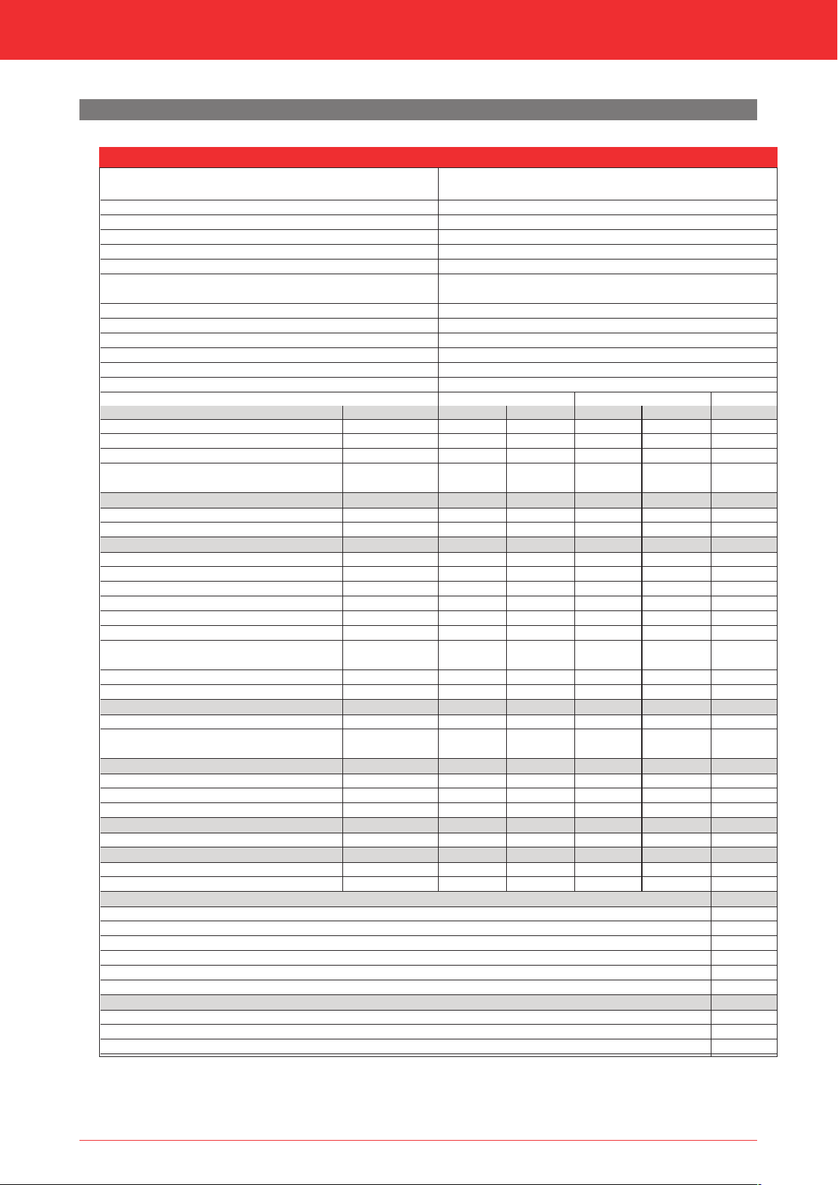
4. Technical data
Check the technical data based on the table below.
Model identifier(s)
Type of appliance
Combustion
Type
Categorie
Concentric appliance connection
Applicable concentric systems
Flame protection version
Atmosphere safety
Explosion hatch
Max. temp. outer tube concentric system
Radiation range safe distance (front/side)
Ventilation hole chimney breast
Installation manual
Table 4-1: Technical data
Maestro 80/2 RCH
Maestro 80/3 RCH
Built-in
Closed combustion
C11, C31, C91, C12, C32*****
I
, I
, I
, I
2E
2E+
, I2H, II
2EK
2ELL
2H3+
, II
, II
, II
2E+3+
2H3B/P
2E3B/P
, II
2EK3B/P
200/130
DRU LAS ES-I 200/130, DRU LAS ES-E 200/150/100,
DRU LAS ES-I 150/100, DRU PV-I 100/60
Separated ignition / ionization plugs
No
Yes
160°C
800 mm
V-in: 80 cm
2
/ V-out: 200 cm
2
Gastype:
Indirect heating functionality
Direct heat output
Indirect heat output
Space heating emissions NO
x
Symbol
G25/G25.3*
No
8,6
-
111,0
G20
No
9,0
-
118,4
Heat output
Nominal heat output
Minimum heat output (indicative)
P
nom
P
min
8,6
1,3
9,0
1,4
Technical data
Nominal heat input (Hs)
Nominal heat input (Hi)
Consumption max
Consumption min
Burner pressure max
Burner pressure min
Main burner injector
Low setting injector
Efficiency class (EN613)
11,4
10,3
1223
209
18,7
4,2
2x Ø1,65
1x Ø1,55
A****
1
12,0
10,8
1140
218
14,7
4,7
2x Ø1,65
1x Ø1,55
A****
1
Useful efficiency (NCV)**
Useful efficiency at nominal heat output
Useful efficiency at minimum heat output
η
η
th,nom
th,min
91,6
71,4
93,0
72,0
(indicative)
Auxiliary electricity consumption
At nominal heat output
At minimum heat output
In standby mode
el
max
el
min
el
SB
0,0236
0,0125
0,0026
0,0236
0,0125
0,0026
Permanent pilot flame power requirement
Pilot flame power requirement (if applicable)
P
pilot
-
-
Energy efficiency
Energy efficiency index
Energy efficiency class
EEI
91
A
93
A
Type of heat output / room temperature control
Single stage heat output, no room temperature control
Two or more manual stages, no room temperature control
With mechanic thermostat room temperature control
With electronic room temperature control
With electronic room temperature control plus day timer
With electronic room temperature control plus week timer
Other control options
Room temperature control, with presence detection
Room temperature control, with open window detection
With distance controle option
* This appliance is suitable for G25.3 with the composition according NTA 8837.
** System efficiency.
*** To be used by means of home automation.
**** Adjusting screw.
***** Categories C12 and C13 only in combination with DRU PV-1 100/60 (PowerVent®).
G30
No
9,0
-
110,7
9,0
1,6
12,7
11,7
358
69
26,5
10,1
2x Ø1,10
1x Ø1,00
A****
1
89,6
88,5
0,0236
0,0125
0,0026
-
89
A
G31
No
7,8
-
91,0
7,8
1,4
11,2
10,3
415
80
26,9
10,4
2x Ø1,10
1x Ø1,00
A****
1
88,6
88,3
0,0236
0,0125
0,0026
-
89
A
Unit
kW
kW
mg/kWh
(GCV)
kW
kW
kW
kW
L/h
L/h
mbar
mbar
mm
mm
%
%
kW
kW
kW
kW
No
No
No
Yes
Yes
Yes
Yes***
Yes***
Yes
input
6

Installation manual
5. SAFETY
5.1 General
3 - Observe the generally applicable regulations and precautions/safety instructions in this manual.
- First check that the technical execution of the appliance to be installed is correct (see table 4-1).
- Read this manual carefully to ensure the proper and safe installation of the appliance.
- Observe the regulations/instructions in this manual.
5.2 Regulations
Please install the appliance in accordance with the applicable national, local and constructional (installation) regulations.
5.3 Safety instructions
Carefully observe the following precautions/safety instructions:
3 The appliance may only be installed and maintained by recognised installers who are skilled in the field of gas heating
and electricity.
3 Do not make any changes to the appliance.
3 When installing a built-in appliance:
- Use non combustible and heat-resistant materials for the chimney breast, including the top of the chimney breast, the
material in the chimney breast and the back wall against which the appliance will be placed. For this you can use both
sheet material and stone-like materials.
- Take sufficient measures to prevent temperatures of a wall behind the chimney breast becoming too high, including
the materials and/or objects behind the wall.
- Comply with the minimum required internal dimensions of the chimney breast.
- Ventilate the chimney breast by means of ventilation holes (see table 4-1).
- Use heat resistant electrical connectors.
- Place heat-resistant electrical wiring away from the appliance and as low as possible in the chimney breast. This has to
do with the temperature development in the chimney breast.
- Only use the flue gas discharge / combustion air supply system (concentric system) supplied by DRU.
3 When installing a free-standing appliance: place the appliance at the indicated minimum distance from the back wall, as
indicated further down in the text.
3 Do not cover the appliance and/or do not wrap it in an insulation blanket or any other material.
3 Keep combustible objects and/or materials outside the appliance's radiation range (see table 4-1).
3 Only use the accompanying set, such as the wood or pebble set, and place it exactly as described.
3 Leave space around the ionisation pin and spark electrode and never place glow material around these pins.
3 Make sure there is no dirt in gas pipes and connections.
3 Place a gas tap in accordance with applicable regulations.
3 Check the complete installation for gas tightness prior to commissioning.
3 Prevent the explosion hatch(es) on the top of the appliance (if present) from getting clogged and check that they
properly fit on the sealing surface, before the appliance is built in.
3 Do not ignite the appliance until it is fully installed when it comes to the gas connections, discharge system and electrical
components.
3 Do not use the appliance when a pane is broken and/or cracked, until it has been replaced.
3 The appliance was designed for atmospheric and heating purposes. This means that all visible surfaces, including the
glass pane, can become hotter than 100C°. It is recommended to always place a protective grating in front of the
appliance when there are children, elderly people or handicapped persons in the same room as the appliance.
If it is possible that vulnerable people are regularly present in the room with no supervision, a fixed guard should be
mounted around the appliance.
7
Installation manual
6. Preparation
6.1 Unpacking
Note the following items when removing the packaging:
1 Remove all packaging materials.
1 Remove all supplied components in, on and/or at the appliance.
1 Check the appliance and accessories for damages (during transport).
1 If necessary, contact your supplier.
1 Never install an appliance that is damaged!
1 Remove any screws that are used to fix the appliance to a platform or pallet.
3 The glass pane(s) is/are made of a ceramic material. Very small irregularities in the glass panes cannot be avoided, but are
within the required quality standards.
3 Keep plastic bags away from children.
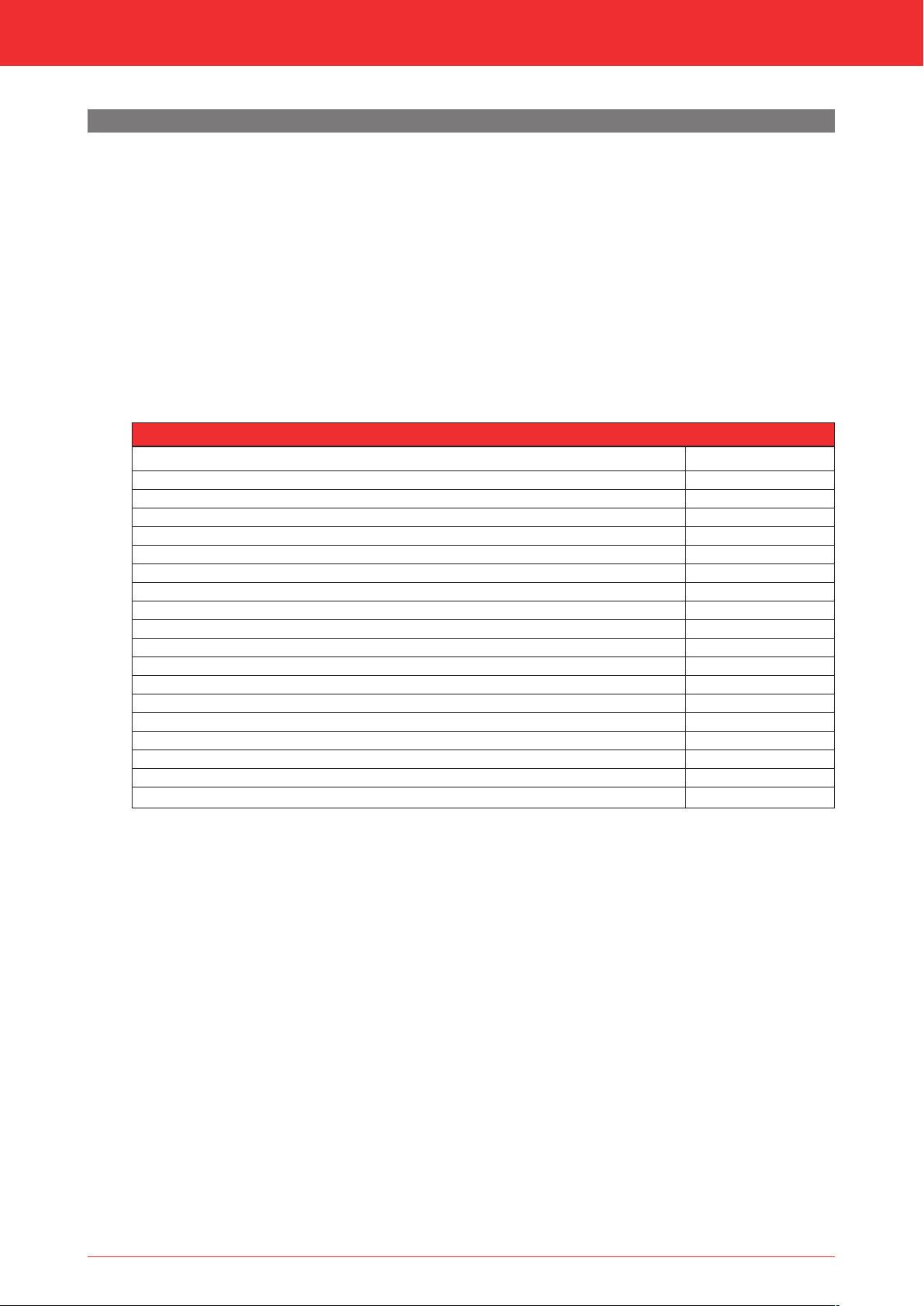
Table 6-1 indicates which components should be available after removing the packaging.
1 Contact the supplier if you find that not all components have been supplied.
1 Packaging must be disposed of in accordance with the regulations.
Table 6-1: Parts included with the delivery
Part
Installation manual
User manual
Wood set (including: chips, vermiculite and ash)
Glow material
Restrictor slide
Air inlet guide
Remote control
Mains cable
Control hatch
Wall bracket
Assembly set platform
Mantle iron
Back-up self-tapping screw for benefit of glass pane assembly
Key bolt M8 (including: Hexagonal nut M8 and Washer M8)
Compression fitting 15 mm x G3/8”
Socket spanner 8 mm
Allen key 2.5 mm
Suction cup (only Maestro 80/2 RCH)
Number
1x
1x
1x
1x
1x
1x
1x
1x
1x
1x
Separately available
Separately available
nx
4x
1x
1x
1x
1x
6.2 Type of gas
The data plate indicates for which type of gas, gas pressure and for which country this appliance is intended.
The data plate can be found on the appliance or can be attached to a chain to which it should remain attached.
3 Check whether the appliance is suitable for the type of gas and the gas pressure used at the location.
6.2.1 Gas type conversion
In order to convert this appliance to a different type of gas, please contact DRU's service department and ask for
the possibilities. The conversion should be performed by a recognised gas installer.
6.3 Gas connection
Place a gas tap in the gas pipe in accordance with the applicable regulations. The gas connection on the gas control is
located next to the receiver (fig. 6-1 (G
3 - Make sure there is no dirt in the gas pipes and connections.
- No soldering may take place at the flexible gas hose(s), as this could cause leaks.
The following requirements apply to the gas connection:
- Use a gas pipe with the correct dimensions, so that no pressure loss can occur.
- The gas tap must be approved (in the EU this will be the CE mark).
- You should always be able to reach the gas tap.
)).
in
8
Installation manual
300 mm
38C-2605
≥ 20 mm
≥ Ø 40 mm
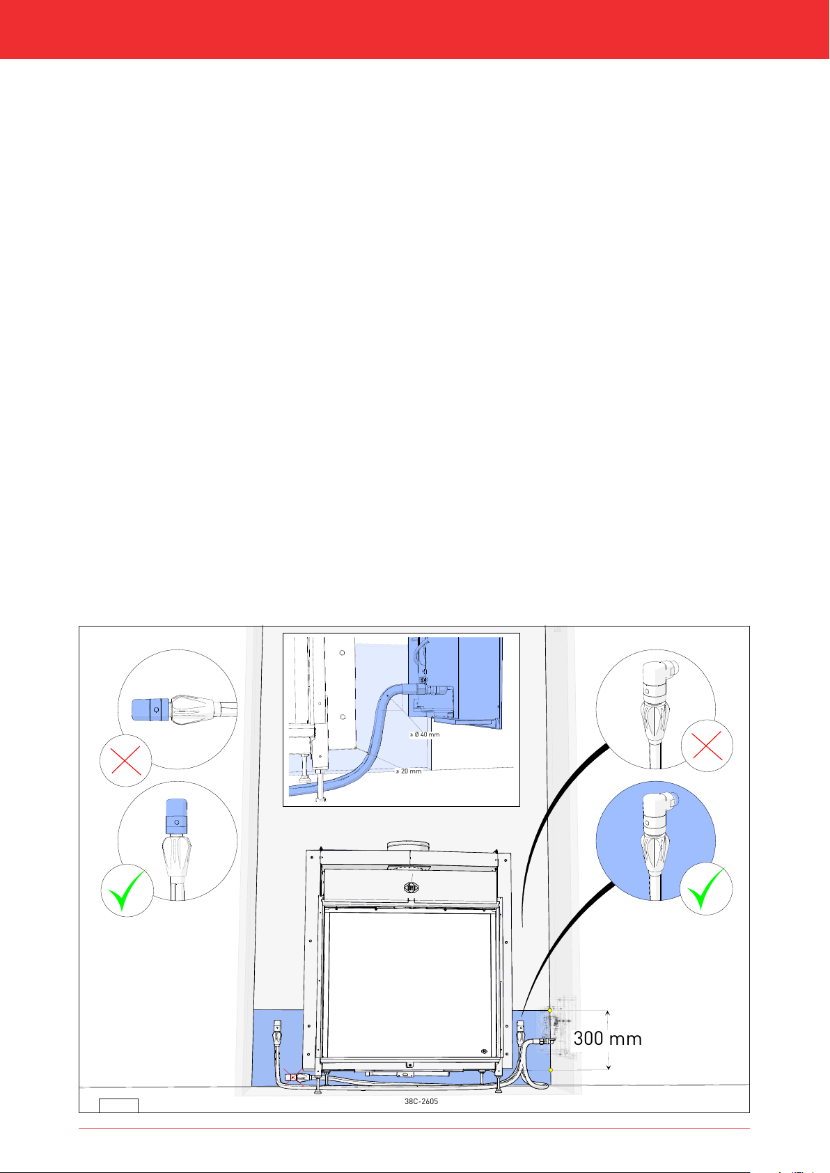
6.3.1 Gas hose for gas connection
In many cases, a gas hose for a gas connection according to EN14800 can be ordered together with the appliance. The
gas hose is mounted to the appliance and has been checked for leak-tightness. This gas hose is available in different
lengths.
Take the following into account when installing the gas connection and the appliance (see fig. 6-1):
- The gas connection must always be accessible to be able to shut off the gas supply.
- The gas connection may only be mounted vertically, so that the gas hose can be connected vertically at the bottom.
- The gas connection is permitted in a zone (blue hatched area in fig. 6-1). To the left and right of the appliance to a
height of 30 cm above the bottom side of the appliance (the bottom side is the end of the adjustable feet holder,
without the feet). Under the appliance in the area between the legs.
- The gas connection and gas hose should not be placed behind the appliance.
- The gas hose may not get above the bottom side of the appliance (the bottom side is the end of the foot without the
adjustable feet)
- The minimum bend radius of the hose is 40 mm.
- The hose should be placed as low as possible, must have a minimum distance from the appliance of 20 mm and, if
possible, should not be placed under the burner.
- The entrance of the gas control in which the hose is mounted faces the appliance. Due to the bend radius, the chimney
breast width becomes larger on the side of the control hatch. The minimal depth of the control hatch is 270 mm.
6.4 Electric connection
In case of an electrical connection of 230 Volts, always provide sufficient earthing. Place this electrical connection away
from the appliance, as low as possible in the chimney breast. Make sure the electrical connection is within reach. This has
to do with the temperature development in the chimney breast.
3 Make sure that it is easy to disconnect the appliance from the power supply after installation: By disconnecting the
plug or by means of a 2-core switch installed by a recognised installer in accordance with current regulations.
3 - Protect the gas control and electric components, hereafter referred to as the gas control, against building dust and
moisture!
- In the case of appliances made with the CM system
the receiver and control panel.
®
, observe the instructions in the supplied manual for connecting
6-1
9
Installation manual
C
B
D
38p-0318 /3
P1
P2
G (IN)
A
E
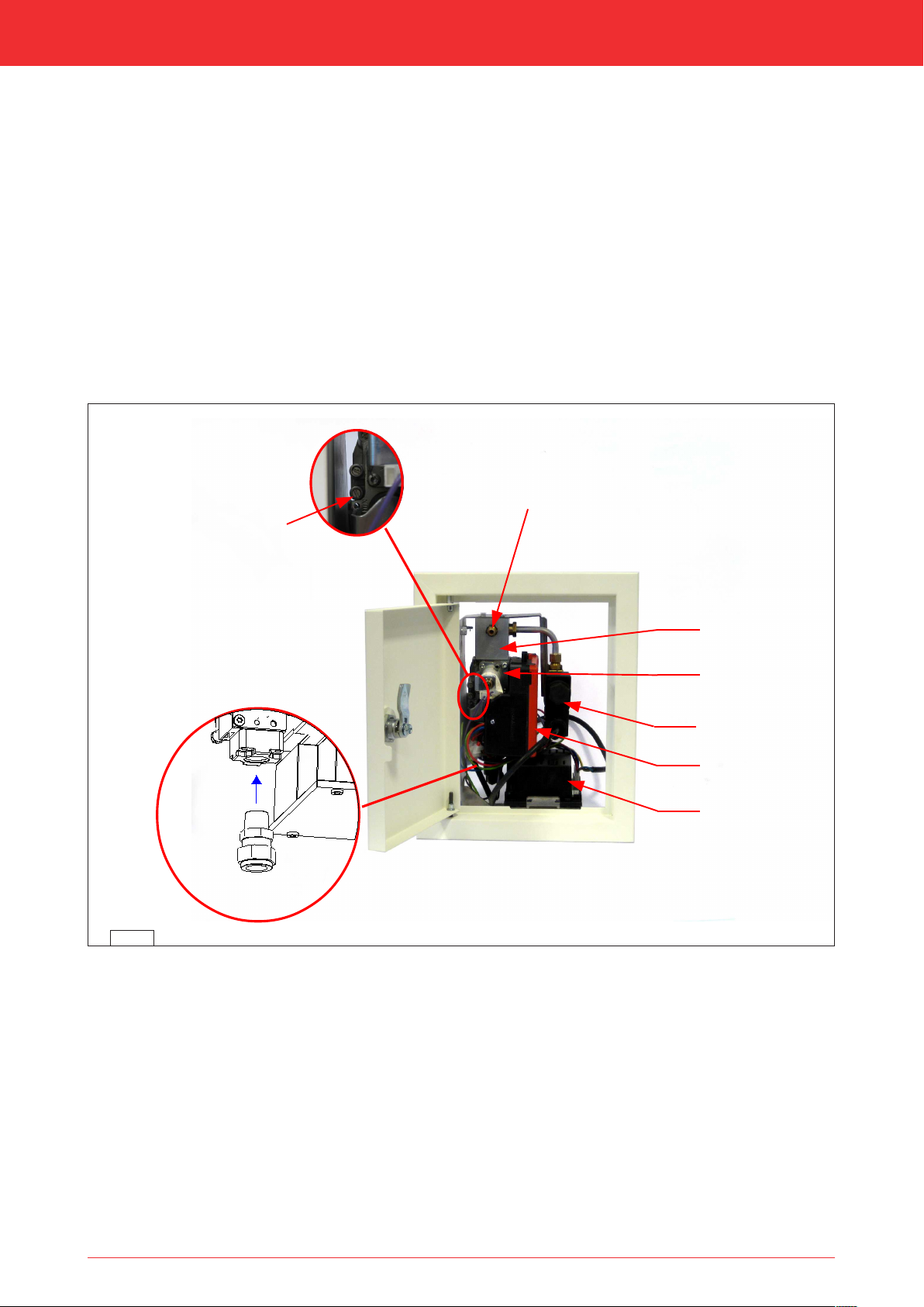
6.5 Components appliance control
This section states the components that are used to control the appliance (see fig. 6-2).
6-1
Legend:
A = Gas control; controls the gas to the burners
B = Receiver; communicates with the transmitter
C = Processor (ESYS); controls the gas control
D = Distribution block; connection of the burners
E = Valve 2nd burner; opens and closes the gas supply to the 2nd burner (if applicable)
P1 = Pressure gauge nipple 1; line-pressure
P2 = Pressure gauge nipple 2; burner pressure
G (IN) = Gas connection; connection from the gas control to the gas network
10
Installation manual
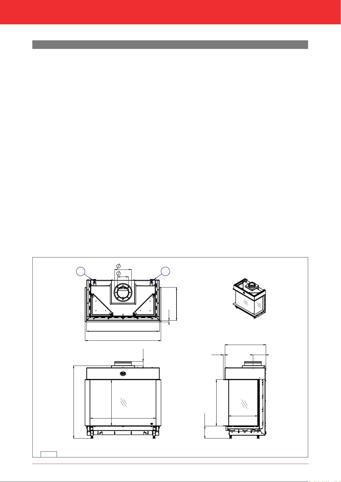
790
550
min. 873
max. 923
50
876
912
396
18
200
130
A
A
558
min. 148
max. 198
349
156
492
18
38c-2251 /0
Maestro 80-3 RCH
7 Installation
7.1 Placing the appliance
Separate sub-sections describe different ways of placing the appliance. The general description below for placing the
appliance applies to all these sub-sections:
1 Place the appliance where it will be installed and observe the following:
- The construction dimensions of the appliance (see fig. 7-1 and 7-2).
- The minimum chimney breast dimensions (see section 7-4).
- The length of the cables and pipes (see section 7-4).
- Place the appliance in front of a heat-resistant and non combustible wall. The wall brackets on a built-in appliance
ensure that the minimum distance to the wall is maintained (see fig. 7-1 (A)).
- Take sufficient measures to prevent temperatures of a possible wall behind the chimney breast becoming too high,
including the materials and/or objects behind the wall.
- Make sure there are no combustible objects or materials within the radiation range (see table 4-1 and fig. 7-12) of the
fire.
- Place the concentric system in such a way that no fire hazard can ever be created (see section 7.3).
- Do not cover the appliance and/or do not wrap it in an insulation blanket or any other material.
- Make sure that the appliance to be installed has a stable position. Fasten possible extending legs with the self-tapping
screws.
Proceed as follows:
1 Loosen the bracket with the gas control by loosening the self-tapping screws and screw the self-tapping screws back in
the appliance.
1 Place the bracket with the gas control, together with the wiring of the ignition/ionization cable(s), the flexible gas hose(s)
and the data plate with chain in the direction of the control hatch (see section 7.5)..
3 - Do not lay the cables of the ionisation and ignition pins along metal parts, wiring and other components.
- The data plate should remain attached to the chain.
7-1
11
Installation manual
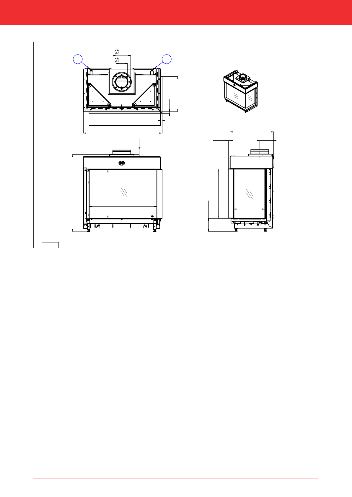
min. 873
max. 923
50
760
550
807
18
887
396
18
200
130
AA
156
492
18
349
558
min. 148
max. 198
38c-2252 /0
Maestro 80-2 R RCH
7-2
12
Installation manual
2
1
3
4
4
74
38C-2499
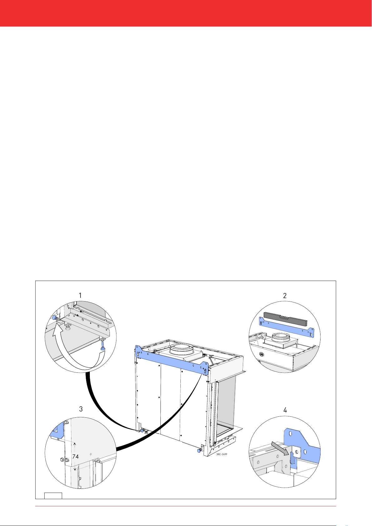
7.1.1 Standing installation of the appliance
In case of a standing installation of the appliance, observe the following instructions:
1 Set the height of the appliance using the adjustable feet and level the appliance.
1 Attach the appliance to the wall using wall brackets (see fig. 7-1 (A) or 7-2 (A)).
7.1.2 Suspended installation of the appliance
In case of a suspended installation of the appliance, observe the following instructions:
1 Determine the location and height of the appliance (see fig. 7-1 or 7-2) and the control hatch (see fig. 7-14)).
1 Attach the suspension bracket to the wall using the supplied key bolts (see fig. 7-3).
3 Attach the appliance to a vertical wall of solid, non combustible and heat-resistant material.
1 Use the slotted holes of the suspension bracket to level the appliance.
1 Unscrew the 2 adjustable feet (1) with lock nut from under the appliance and place
them in the rear of the appliance.
1 Place the appliance in the suspension bracket. Wall bracket hangs in the suspension bracket (see fig. 7-3(4)).
1 Use the adjustable feet (1) to level the appliance vertically and lock them with the nut.
7-3
13

Installation manual
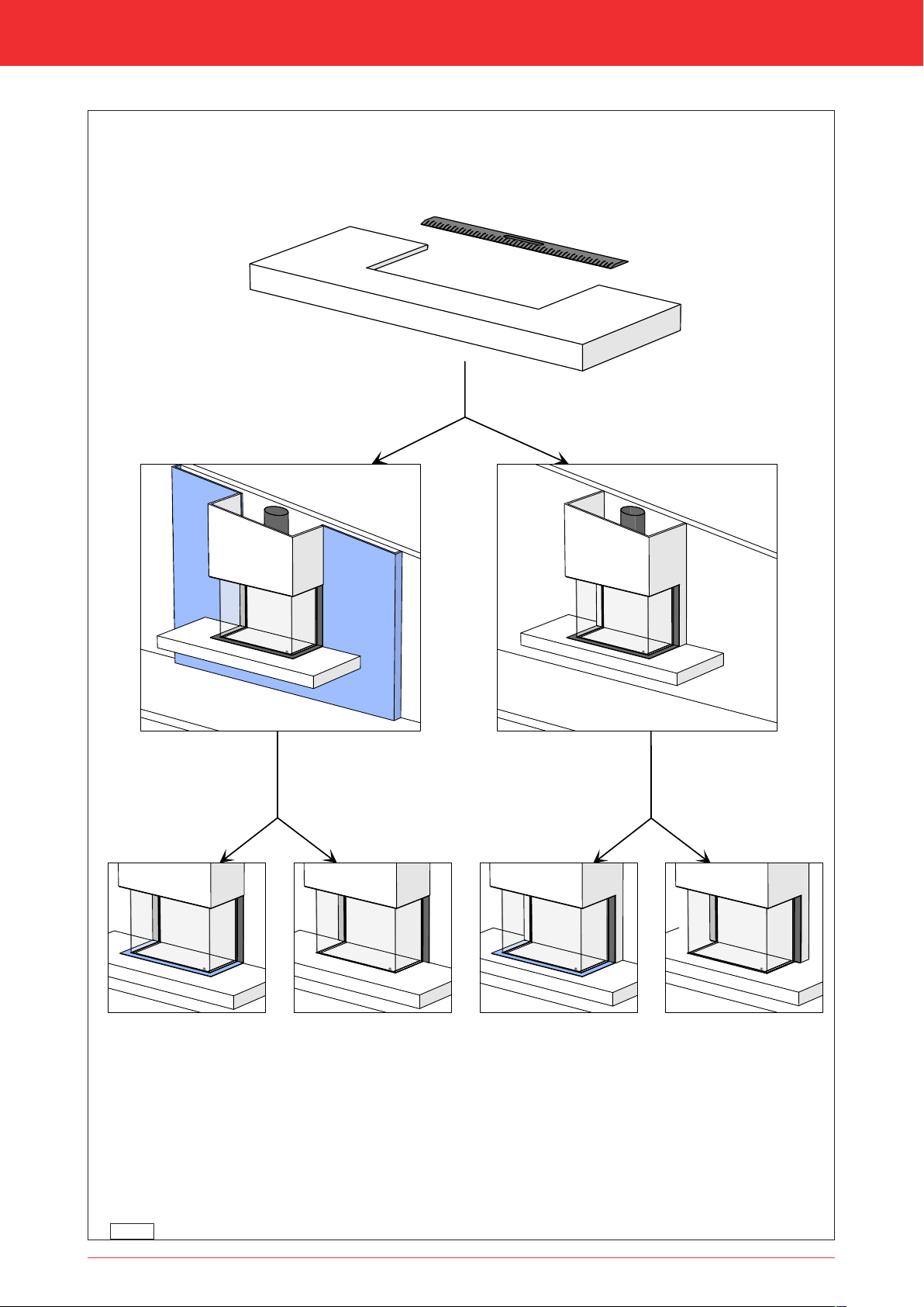
7.2 Additional installation options
The appliance can be placed with a platform. This can be done in combination with a lower decorative strip or with the
platform connecting to the glass. The accompanying chimney breast can be used with or without a false wall (see fig. 7-4
and 7-5).
It is also possible to have the interior plate of the appliance continue to the outside. In that case, the chimney breast or
other heat-resistant materials can be placed up to the side pane(s) (see fig. 7-6).
3 Do not allow the weight of the platform to rest on the appliance, use the assembly set instead. It can be ordered
separately.
7.2.1 Platform combined with lower decorative strip
(see fig. 7-4 (A and C) and 7-5 (A and C))
1 Create a recess in the platform, in which the appliance will be placed. If a false wall is used, the recess will be less deep.
1 Mutually adjust the height of the appliance and assembly set, so that the top side of the platform connects to the bottom
side of the lower decorative strip.
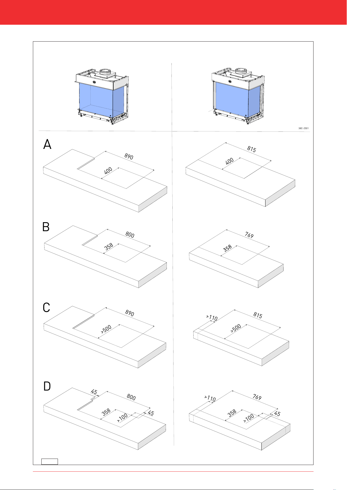
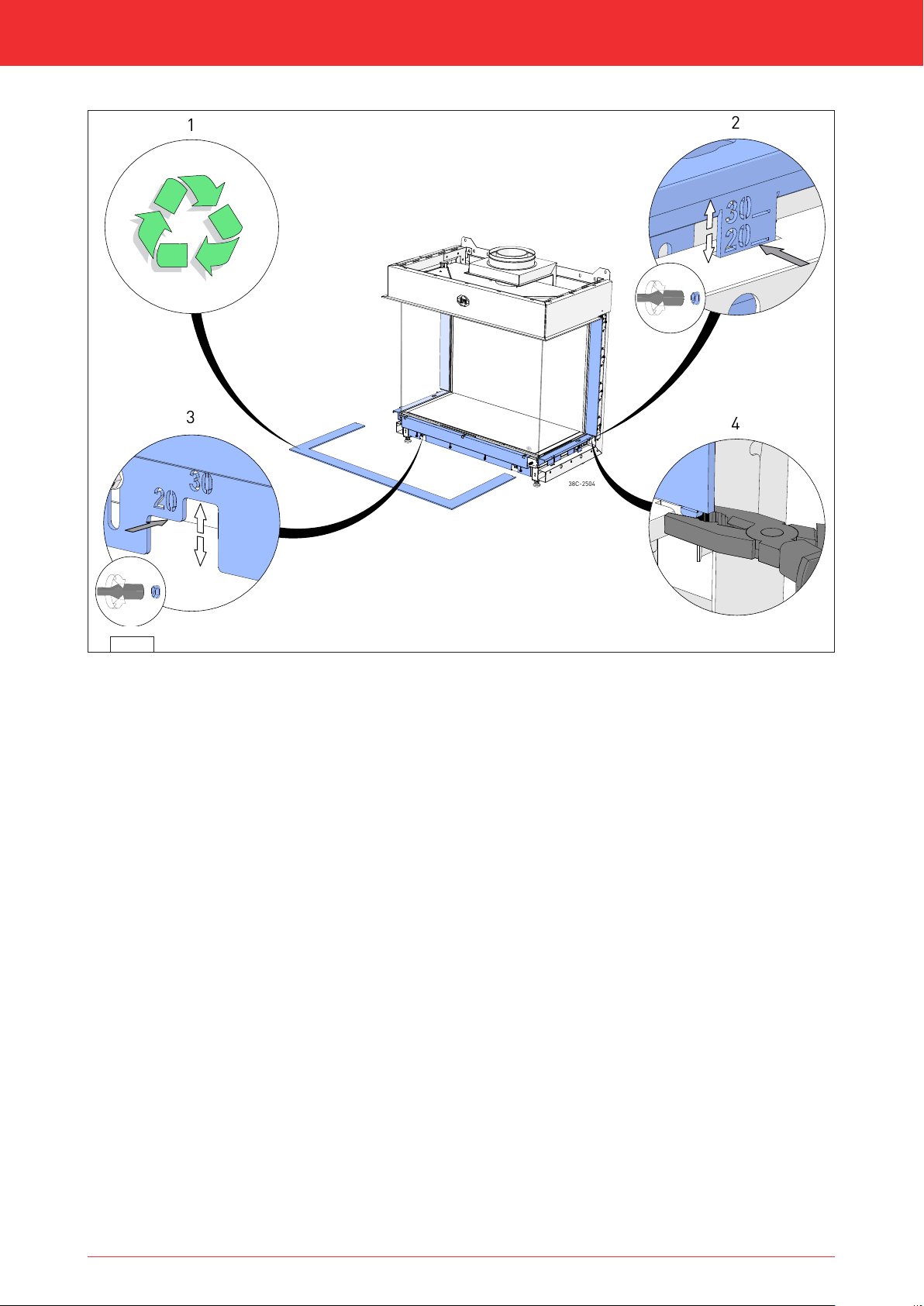
7.2.2 Platform connecting to the glass
(see fig. 7-4 (B and D) and 7-5 (B and D))
1 Create a recess in the platform, in which the appliance will be placed. If a false wall is used, the recess will be less deep.
Maximum material thickness is 30 mm.
1 Remove the lower decorative strip (see fig. 7-6) by sliding it forward and taking it out. It will not be placed back.
1 Remove the centring cam at the bottom of the decorative strip by cutting into it at the front and breaking it off.
Make sure the bottom side of the decorative strip remains flat and resistant to corrosion.
1 Loosen the nuts of the adjustable profiles by a few turns and adjust the profiles to the correct height. The height depends
on the material thickness of the platform. For material thickness 20 mm and 30 mm, indicators have been applied.
Re-tighten the nuts (see fig. 7-6).
1 Mutually adjust the height of the appliance and assembly set, so that the bottom side of the platform connects to the
adjustable profiles.
3 - Do not allow the weight of the platform to rest on the appliance and/or the adjustable profile.
- Make sure there is sufficient space between the platform and the springy glass pane strip in order to be able to
remove/place the front glass pane. Use the end stops on both sides of the appliance.
14
Installation manual
A DB C
38C-2500
7-4
15
Installation manual
C
38C-2501
D
A
B
45
890
400
800
890
>500
800
>100
358
815
358
358
769
400
769
358
>100
45
815
>500
>110
45
>110
7-5
16
Installation manual
1
3
4
2
38C-2504
tooltip
tooltip
7-6
17

Installation manual
7.2.3 Placement of bracket with gas control and accessories below the platform
3 If, when placing with a platform, there is no room for the control hatch, the bracket with gas control must be placed
directly under the platform using the 'electricity protective cabinet' accessory.
Place the bracket with gas control and accessories below the platform using the supplied protective cabinet (see fig. 7-7).
1 Place the attachment bracket (A) against the back wall using suitable fastening materials. Make sure the top of the
bracket connects to the platform;
3 It is not allowed to place the bracket under the appliance.
1 Loosen the bracket with gas control and accessories (B) from the appliance and attach it to the attachment bracket (A)
using the previously removed self-tapping screws.
3 Never allow the bracket with gas control and accessories to remain attached to the appliance and remove the
transportation bracket.
1 Position the gas pipe on the recess (1) in the protective cabinet, it is aligned with the connection on the gas control.
1 Connect the gas pipe as described in section 6.3.
1 Place the data plate (C) in the bracket in the bottom of the protective hood (D).
1 Hook the protective hood into bracket (A) and fasten it with the self-tapping screw.
1 Guide the flexible gas pipe that leads to the burner through the recess (2).
1 Guide the cables through the protected recess (3).
3 Make sure the cables of the ionization pin and spark electrode do not make contact with metal parts. These may also not
make contact with signal and voltage cables.
1 Use cable ties to fasten cables and pipes.
3 - There are 230V of mains voltage on the gas unit, and this must be guarded.
- Carefully observe the necessary safety instructions that also apply to the control hatch (see section 7.5).
18

Installation manual
38c-1955/0
1
2
3
I
A
B
II
III
IV
V
VI
D
C
7-7
19

Installation manual
7.2.4 Back wall connecting to the glass of the side pane
(see fig. 7-8 and 7-9)
When installing the wall up to the side pane, proceed as follows:
1 Make sure the back wall to be placed has the correct dimensions (see fig. 7-8).
1 Loosen the self-tapping screws of the vertical decorative strip by a few turns and adjust the profiles to the correct
distance. The distance depends on the thickness of the wall. For material thickness 20 mm and 30 mm, indicators have
been applied. The cover plate is no longer required and can be removed. Re-tighten the self-tapping screws (see fig. 7-9).
1 Maintain a 5 mm distance between the wall and the side pane.
3 - In case of a 2-sided appliance, construction on the glass of the side pane is only possible at the back wall side, not at
the side wall side. It has to be possible to remove the front glass pane. For this purpose, it should be possible to remove
the decorative strip.
- In case of materials up to the glass, it is important to maintain a 5 mm minimum distance from the glass!
- In case of materials up to the glass, heat-resistant material should be used that is at least able to resist a temperature of
85°C.
20
 Loading...