

Page 1
English
Largo - Largo Tunne
l
Please retain this document carefull
y
nstructions for installation
GB / IE)
UK
Page 2

English
L
ARGO - INSTRUCTION FOR INSTALLATIO
N
Contents
pa
ge
For
eword
1. Introduction
3
2. EC Declaration of Conformit
y
3
3
. SAFETY
3
3.1 Genera
l
3
3.2 Regulations
3
3.3 Precautionary measures / safety instructions regarding installation
3
4. Instructions
4
5. Unpackin
g
4
6
. Installation
4
6.1 Regulations
4
6.2 Gas type
4
6.3 Gas connection
4
6.4 Positioning the appliance
5
6.5 Flue gas discharge / combustion air supply system
6
6.6 Building the chimney breast
9
6.7 Installing the control box
1
0
6.8 Adjusting the appliance
1
0
6.9 Arranging the logs
1
3
6.10 Glass window
1
4
7
. Wireless remote control
1
6
7
.1 Receiver
1
6
8. Final inspection
1
7
8.1 Gastightness
1
7
8.2 Gas pressure/pre-pressure
1
7
8.3 Igniting the pilot and main burner
1
7
8.4 Flame effect
1
8
9
. Maintenance
1
8
10. Completion
1
8
11. Troubleshooting
1
9
Annex 1 Components supplied
2
1
Annex 2 Technical
data
2
Annex 3 Spare parts
2
Foreword
As manufacturer of gas heating appliances, DRU develops and produces products to meet the highest possible
qualit
y
, performance and safety requirements
.
As a result of which the user is able to enjoy using your appliance for years to come
.
This appliance is CE marked; it complies with the essential requirements of the European Appliance Directive.
The a
pp
liance is supplied with two manuals: the installation manual and the user manual.
You the installer should be professionall
y
skilled in the fi eld of decorative gas heatin
g.
The installation manual gives you all the information you will need to be able to install the appliance in such a way
that it works correctl
y
and safel
y.
This manual deals with the installation of the appliance and the appropriate regulations. It also includes the techni
-
cal data for the appliance and information on maintenance and troubleshooting
.
Please read and use this installation manual carefully
.
In the manuals the following symbols are used to denote important information:
➠
What to
do
!Tip
Suggestions and recommendation
s
!
N.B. These instructions are important to avoid possible problems during installation and/or use
.
N.B. These instructions are important to avoid re, personal injury or other serious damage.
Once you have completed the installation you are to hand both the user manual
and
and
this
in
stallatio
n manual to the
user.
UK
Page 3

3
English
ARGO - INSTRUCTION FOR INSTALLATIO
N
1. Introduction
T
he appliance is available in two models, the Largo and the Largo Tunnel
.
T
he Largo is a ‘standard’ gas fi re and should always be installed against a wall. The Largo Tunnel is just that, a ‘tunnel
fi
re’ with both a front and back window.
T
he Largo and the Largo Tunnel are closed decorative fi res. A closed tunnel draws its combustion air from outside and
ot from the living area. This is done by way of a combined system that discharges the fl ue gases and supplies the
c
ombustion air. In this concentric system the outer pipe serves as air supply and the inner pipe as the fl ue
.
T
his system can be installed through either the outer wall or the roof
.
T
he appliances are built into a chimney breast. The DRU product range includes several chimney breasts
.
Th
e chimney breast must be well ventilated to ensure a good heat distribution. DRU can supply various ventilation
elements
.
T
he appliances are supplied with a wireless, battery-operated remote control
.
2. EC Declaration of Conformity
W
e hereby declare that the design and construction of the decorative gas heating appliance marketed by DRU con
-
f
orms with the essential requirements of the Gas Appliance Directive
.
T
his declaration will be rendered invalid should the appliance be altered in any way without the written consent of
.
roduct: Decorative gas heating applianc
e
Ty
pe: Lar
go
Largo Tunne
l
App
licable EC Directives: 90/396/EE
C
App
licable harmonised standards: NEN-EN-613, NEN-EN-613/A
1
n-house measures guarantee that serially produced appliances always conform with the essential requirements of
t
he current EC Directives and the applicable standards
.
. Gelten
RU VERWARMING B.V.
ostbus 1021, 6920 BA Duive
n
atio 8, 6921 RW Duive
n
w
ww.dru.nl
3. SAFETY
3
.1 Genera
l
N.B.
- Please read this chapter on safety carefully before commencing installation or maintenance
;
- Always observe universal regulations and the precautionary measures / safety instructions in this manual
.
3.2 Regulations
T
he appliance should be installed in compliance with current national, local and constructional (installation) regulations
.
3.3 Precautionary measures / safety instructions regarding installatio
n
O
bserve the following precautions / safety regulations precisel
y:
➠
You m ay only install and/or service this appliance if your are a quali ed installer skilled in installing decorative gas res
;
➠
do not adjust the appliance in any way
;
➠
Non-combustible and heat-resistant materials should be used to construct the chimney breast, its rear wall, the interior and the top o
f
the chimney breast;
➠
the minimum internal dimensions required for the chimney breast must be taken into account
;
➠
the chimney breast should be ventilated by vents with total free vent area of 200 cm
;
➠
only use the ue /combustion air supply systems supplied by DRU
;
➠
use the wall brackets supplied to mount the appliance;
➠
do not install the appliance at against the back wall
;
➠
leave the space between the feet free
;
➠
do not cover and/or pack the appliance with an insulating blanket or any other material;
➠
Keep combustible objects and/or materials at a minimum distance of 500 mm from the appliance
.
➠
only use the log set supplie
d;
➠
arrange the logs exactly as described
;
➠
leave a space around the pilot burner
;
➠
avoid any dirt in the gas pipes and connections;
UK
Page 4

4
English
L
ARGO - INSTRUCTION FOR INSTALLATIO
N
➠
test the gastightness of all connections before use
;
➠
use heat-resistant electrical connection materials
;
➠
install the electrical connections away from the appliance;
➠
replace torn or broken panes;
➠
avoid blocking the explosion hatches
;
➠
ensure the explosion hatches on top of the heater are right on their seats, before you close the chimney breast
;
➠
do not ignite the appliance until installation has been completed
.
4. Instructions
To ensure the appliance works correctly and safely, always take the following points into consideration during installation:
➠
place the control box su
pplied
as low as possible;
➠
ensure the ignition wire does not lie across the receiver;
➠
ensure the ignition wire does not touch or cross the aeria
l;
➠
to avoid weakening the spark ensure the ignition wire does not touch anything meta
l;
➠
if the appliance is to be built in ush with the wall, nish the edges neatly
;
➠
do not plaster over the anges;
➠
avoid damaging the glass when removing/ tting the window pane
;
➠
to prevent dirt burning into the glass, make sure it is clean before use
.
5. Unpacking
Please take the following points into consideration when unpacking the appliance
:
➠
Check the appliance for transit damage
;
➠
Contact DRU Service if necessary
.
Once the packaging material has been removed, you should have the following components:
- Socket s
p
anner: You will fi nd this in the space between the assembly frame and the combustion chamber;
- Tr
immi
ngs:These are in the same space
.
Once you have removed the glass pane you can remove the box of components from the combustion chamber.
!
N.B. Be careful not to damage the glass when removing/ tting the window pane
.
➠
Remove the window as described in paragraph 6.10.1
;
➠
Take the box of components out of the combustion chamber
.
Annex 1 / Table 4 specifi es the components you should have once everything has been unpacked.
➠
Contact DRU Service if after unpacking the appliance you do not have all the components;
➠
Dispose of the packaging in an appropriate manner.
6. Installation
Please read the manual carefully to ensure that once installed the appliance will work correctly and safely.
!
N.B. Install the appliance in the order described in this chapter.
6.1 Regulation
s
- Observe the current applicable (installation) regulations
;
- Observe the regulations/instructions laid down in this manual.
6
.2 Gas typ
e
The type plate specifi es the type of gas, gas pressure, and the country this appliance is intended for. The type plate
is on a chain and that is where it should sta
y.
N.B. Check that the appliance is suitable for the local gas type and pressure
.
6.3 Gas connection
The gas connection should have a gas tap located near the appliance
.
N.B.
Prevent any dirt getting into the gas pipes or connections.
The following requirements apply for the gas connection
:
➠
the size of the gas pipe should be such that no pressure loss can occur
;
➠
the gas tap must be CE marke
d;
➠
the gas tap should be accessible at all times;
➠
Do not twist the gas tap when connecting the gas pipe.
UK
Page 5
5
English
ARGO - INSTRUCTION FOR INSTALLATIO
N
6
.4 Positioning the applianc
e
ition the fi re as foll
ows
:
N.B.
- Keep combustible objects and/or materials at a minimum distance of 500 mm from the appliance
.
- Do not adjust the appliance in any way
.
➠
Determine the position of the appliance
;
➠
Create a gas connection in the appropriate position; see section 0 for details
;
➠
Create a duct for the ue / combustion air supply system, with the diameter shown below; see section 6.5 for details;
➠
Ø160 mm for a wall duct of incombustible material
;
➠
Ø 250 mm for a wall duct of combustible material
;
➠
Ø160 mm for a roof duct of incombustible material
;
➠
Ø 250 mm for a roof duct of combustible material.
!
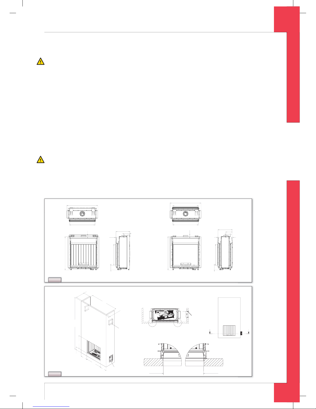
N.B.- Allow for the depth of the appliance (see Fig. 2
)
(Largo: minimum of 450 mm; Largo Tunnel: minimum of 470 mm)
;
- Allow for the build-in height; this will depend on the height of the adjustable feet (see Fig. 1
).
➠
Move the a
ppl
iance into its intended position.
T
he gas control block is mounted onto the burner plate at the bottom of the appliance. This should be removed and
laced in the control box later. See section 7.3 for information on how to fi t the gas control block
.
Commence as follows:
➠
Disconnect the hoses from the gas control block ( exible gas hose, aluminium pilot pipe and thermocouple)
;
➠
Unscrew the self-tapping screw in the burner plate and remove the gas control block
.
N.B.
- Avoid dirt in the hoses
;
- Avoid kinks in the h
oses.
➠
Unroll the hoses towards the control box
;
➠
Unroll the ignition wire towards the control box
.
!
N.B. The type plate should be connected to the chain
.
-BSHP
-BSHPUVOOFM
'SPOUWJFX
5PQWJFX
4JEFWJFX
'SPOUWJFX
5PQWJFX
4JEFWJFX
NJO
NBY
NJO
NBY
NJO
NBY
NJO
NBY
D
D
Fig. 1
C
D
NBYNN
D
NJO
NN
NJONNJOTJEF
NJONN-BSHP5VOOFMJOTJEF
NJO-BSHPJOTJEF
NJO
NN
JOTJEF
5PUBM
WFOUJMBUJPO
DN
$POUSPMCPY
.BYJNBMF
QMBTUFSMJOF
.BYJNBMF
QMBTUFSMJOF
"
"
C
D
""
Fig. 2
UK
Page 6
6
English
L
ARGO - INSTRUCTION FOR INSTALLATIO
N
➠
Lay the chain with the type plate facing the control
box;
➠
Adjust the height of the appliance;
➠
Using a spirit level to ensure it is absolutely level
.
N.B.
- Do not install the appliance at against the back
wa
ll
;
-
Leave the space between the feet free;
-
Do not cover and/or pack the a
ppl
iance with an in
-
sulating blanket or any other materia
l.
➠
Secure the appliance against the wall using the wall
b
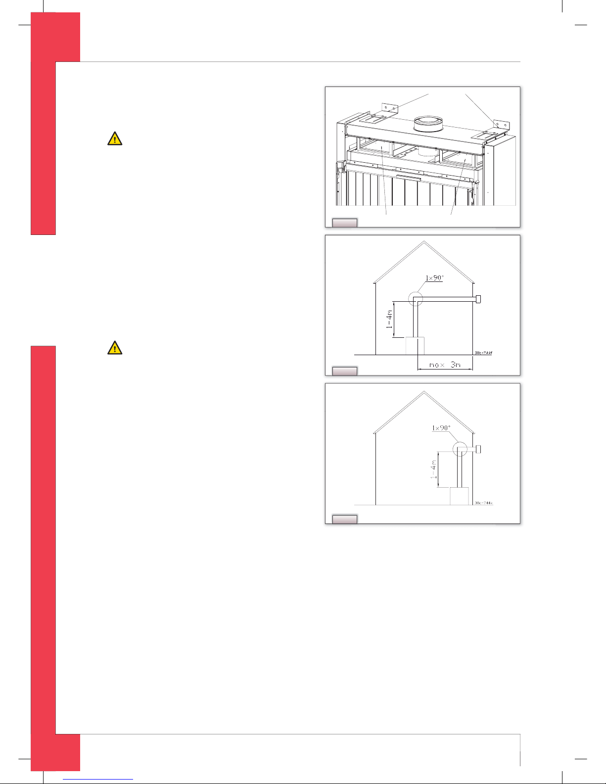
rackets and rawplugs supplied (see Fig. 3).
6.5 Flue gas discharge / combustion air
supply syste
m
6
.5.1 Genera
l
The appliance is of the C11/C31 type
.
The appliance is connected to a combined fl ue gas
dischar
g
e/combustion air supply system, hereafte
r
referred to as the concentric system
.
The passage to the outside can be made with a wall
duct
(
see section 6.5.2) or with a roof duct (see sec
-
tion 6.5.3)
.
If necessary, you can also use an existing discharge
c
h
annel (see section 6.5.4
).
N.B.
- Only use the concentric system supplied by DRU
(
Ø100 / Ø150 mm). This system was tested in com-
b
ination with the appliance; DRU cannot guarantee
a proper and sa
f
e operation of other systems and
cannot accept liability for these systems
;
-
For connecting to an existing chimney ue you
should only use the installation set supplied by
DR
U.
The concentric system is constructed from (the di
-
scharge stump of) the appliance
.
If structural circumstances require that the concen
-
tric system is placed fi rst, the appliance can later be
connecte
d
with a telescopic pipe piece
.
6
.5.2 A
ppl
ication with wall duc
t
6
.5.2.1 Construction of concentric system with
w
all duc
t
The concentric system with wall duct has to comply
with the
f
ollowing conditions
:
➠
First, a concentric pipe of at least 1 meter should be connected vertically to the appliance;
➠
The total vertical pipe length can have a maximum of 4 meters
;
➠
After the vertical part a bend of 90° is connected
;
➠
When using a minimum 1 up to maximum 4 meter vertical pipe length, the total horizontal pipe length may have a
m
aximum of 3 meters (wall duct not included; see Fig. 4a).
Depending on the construction of the concentric system, further adjustments should be made to the appliance.
The next 2 con
fi g
urations are allowed for the construction
:
1) a minimum 1 meter up to maximum 4 meter vertical pipe length in combination with a 90° bend and a wall duct (i.e.
no horizontal
p
art; see Fig. 4b
).
- When using this confi guration, you must not remove the air inlet guides
;
- When using this confi guration, you must not set the restriction.
2) a minimum 1 meter and maximum 4 meter vertical pipe len
g
th in combination with a 90° bend and a maximum
3 meter
h
orizontal pipe length and a wall duct (see Fig. 4a).
- When using this con
fi
guration you must remove the air inlet guides (see section 6.8)
;
- When using this confi guration, you must not set the restriction.
&YQMPTJPOCZQBTTWBMWFT
8BMMCSBDLFUT
D
Fig. 3
Fig. 4a
Fig. 4b
UK
Page 7

7
English
ARGO - INSTRUCTION FOR INSTALLATIO
N
6.5.2.2 Installing the concentric syste
m
T
o install the concentric system commence as follows
:
➠
Construct the system from the (connection stub of the) appliance up
.
N.B.
- Maintain a distance of at least 50 mm between the outside of the concentric system and the walls and/or the ceiling;
I
f the system is built-into a cove for example, incombustible material should be applied all around
;
- Use heat-resistant insulating material for ducts made of combustible material
;
- The rosette (mounting inner plate) of the wall duct is too small to seal the Ø 250 mm opening when passing through
c
ombustible material. That is why you should rst apply a su ciently large heat-resistant intermediate plate to the
wa
ll
. Then, the rosette is mounted on the intermediate plate
.
➠
Connect the concentric pipe sections and the bend(s);
➠
Fit a clamping strip and silicone sealing ring to every connection
;
➠
Secure the clamping strip with a self-tapping screw in places which will be inaccessible after installation;
➠
Use enough brackets to ensure that the weight of the pipes does not rest on the appliance;
➠
Determine the remaining length of the wall duct
;
➠
Cut the wall duct to size
;
!
N.B.- Make sure that the right insertion length is maintained
;
- Place the wall duct with the groove/folded seam at the top;
- Make sure the horizontal concentric pipe pieces are sloping towards the wall duct, in order to prevent rain water
f
rom entering.
➠
Mount the rosette (mounting inner plate); if necessary, on a heat resistant intermediate plate when passing through
c
ombustible material
;
➠
Attach the wall duct from the outside with four screws in their respective holes
.
!
N.B. Some heat-resistant isolation materials contain volatile components that will spread an unpleasant smell for a pro-
l
onged time; these are not suitable
.
6.5.3 Application with roof duc
t
6.5.3.1 Construction of concentric system with roof duc
t
T
he concentric system with roof duct has to comply with the following conditions
➠
The construction of the chosen system has to be allowed. (See the procedure described below)
;
➠
First, a concentric pipe of at least 1 meter should be connected vertically to the appliance
.
epending on the construction of the concentric system, the appliance is set by placing the baffl e and/or removing
t
he air inlet guides
.
n the following procedure you can see how the allowability of a concentric system can be determined and which
s
ettings are neede
d.
➠
Determine the following data:
1
. The number of bends required (no distinction is made between 45° and 90° bends
);
2
. The total number of meters of horizontal pipe length
;
3
. The total number of meters of vertical and/or sloping pipe length (wall duct not included)
.
With th
ese data and Table 1 you will be able to determine whether the concentric system is allowe
d.
n Table 2 you can see which setting the appliance needs
.
ollow the procedure described below
:
➠
In the rst 2 columns of Table 1, look for the number of bends required and the total horizontal pipe length
;
➠
In the 3rd column of Table 1, look for the total vertical and/or sloping pipe length.
f you end up in a box with the letter A, B, C or D the concentric system chosen by you is allowed.
➠
Use Table 2 to determine which conditions apply for the ba e and/or the air inlet guides (for setting see section 6.8);
UK
Page 8
8
English
L
ARGO - INSTRUCTION FOR INSTALLATIO
N
Examples
To clarif
y
, we will give 2 examples to determine the allowability of a concentric system and the conditions for setting the
appliance. In Table 1 the route to be followed is indicated b
y
arrows. The result is indicated by a box with a red border.
Exam
p
le
1
1) 2 bend
s
2) 3 meters horizonta
l
3) 8 meters vertical/slopin
g
Construction of this concentric system is allowed
.
Situation C applies for the adjustment of the appliance
.
Example
2
1) 3 ben
ds
2) 4 meters horizonta
l
3) 10 meters vertical/slopin
g
Construction of this concentric system is not allowed
.
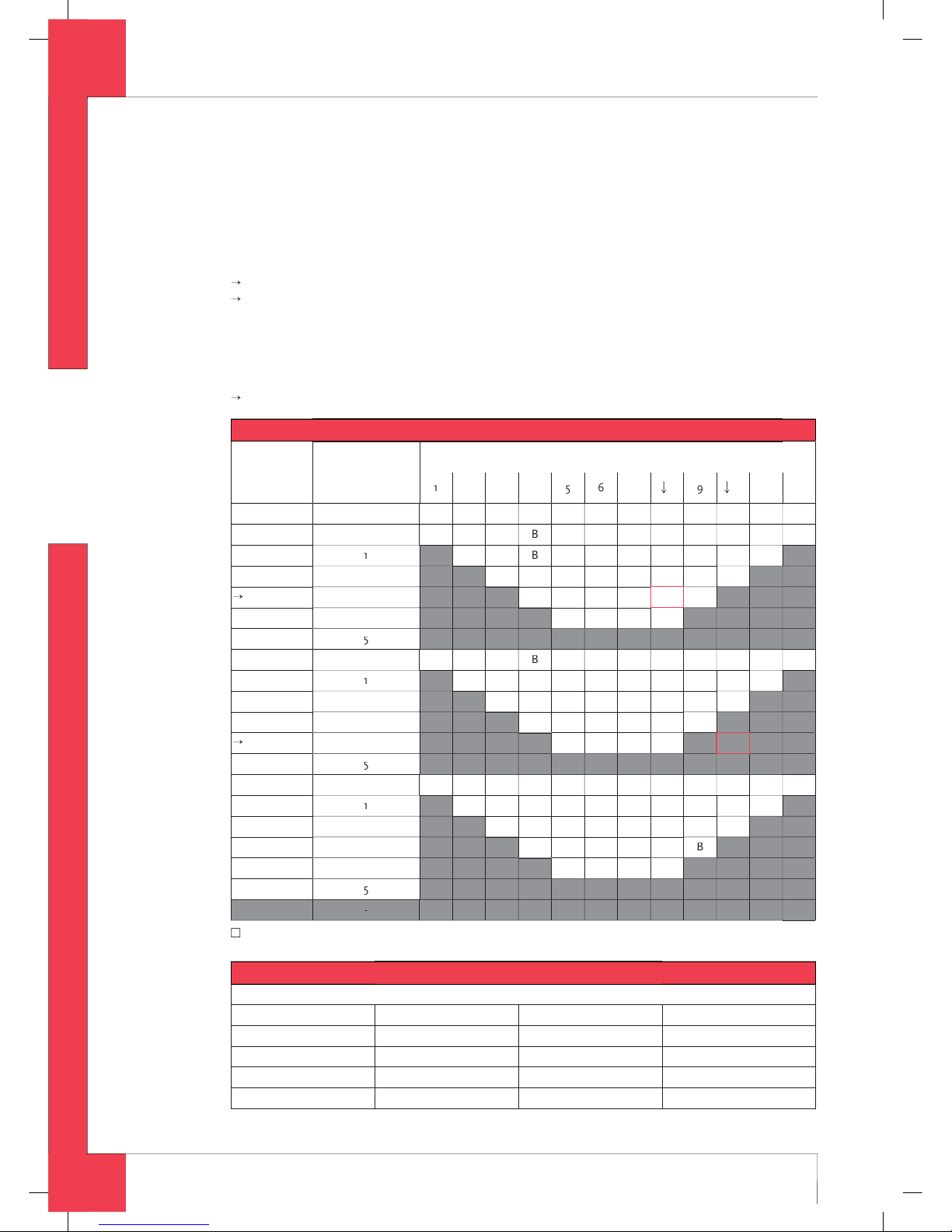
Table 1: Determination of the permissibility of a concentric system with a roof duct
G
20 / G25
T
otal number of
rs horizontal
ipe lengt
h
T
otal number of meters vertical and/or inclined pipe length
3
4
5
6
7
8
9
10
ben
ds
0
CCC
2 bends
0
CCC
CCC
CCC
3
A
A
C
C
4
A
A
5
3
bends
0
CCC
CCC
CCC
3
C
4
AAA
5
4
bends
0
CCC
CCC
C
C
3
4
5
5 bend
s
■ = Situation is not allowe
d
Table 2: Conditions for the adjustment of the appliance with a roof duct
G20/
G25
S
i
tuatio
n
A
ir inlet guide
s
Baffl
e
istance of restriction in mm
N
O
PEN
YE
SES
YE
SES
4
9
YE
SES
UK
Page 9

English
ARGO - INSTRUCTION FOR INSTALLATIO
N
6.5.3.2 Installing the concentric syste
m
he roof duct can be used for either a sloping roof or a fl at roof.
he roof duct can be supplied with an adhesive plate for a fl at roof or with a universally adjustable tile for a sloping roof
.
nstall the concentric system as follows
:
➠
Construct the system from the (connection stub of the) appliance u
p
.B. - Maintain a distance of at least 50 mm between the outside of the concentric system and the walls and/or the ceiling;
the system is built-into a cove for example, incombustible material should be applied all around
;
- Use heat-resistant insulating material for ducts made of combustible material
.
N.B. Some heat-resistant isolation materials contain volatile components that will spread an unpleasant smell for a pro-
lon
g
ed time; these are not suitable
.
➠
Connect the concentric pipe sections and any necessary bends;
➠
Fit a clamping strip and silicone sealing ring to every connection
;
➠
Secure the clamping strip with a self-tapping screw in places which will be inaccessible after installation;
➠
Use enough brackets to ensure that the weight of the pipes does not rest on the appliance;
➠
Determine the remaining length of the roof duct;
➠
Cut the roof duct to size.
!N.B. Be sure to maintain the correct insertion length.
➠
Connect the roof duct to the concentric pipes
.
N.B. - Make sure the universal roof tile ts well against the surrounding tiles
;
- Make sure the adhesive ashing sticks to the at roof properly
.
6.5.4 Connection to an existing fl u
e
he appliance can also be connected to an existing fl ue.
fl exible SS pipe is placed in the chimney for discharging fl ue gases. The surrounding space is used to supply the
ombustion air.
he following requirements apply for connection to an existing fl ue:
allowed only if the special DRU chimney connection set is used
;
Installation instructions supplied;
minimum dimensions 150 x 150 mm;
maximum vertical length 12 metres;
maximum horizontal length 3 metres;
the existing fl ue must be clean;
the existing fl ue must not have any cracks or leaks
.
.6 Building the chimney breas
t
he appliance is designed to be installed snugly into a newly built chimney breast
.
here must be suffi cient space around the appliance to ensure a good heat distribution
.
he chimney breast should be ventilated by vents
.
.B. - Use incombustible and heat-resistant material to construct the chimney breast, including rear wall of the chimne
y
breast
;
- The total free vent area of the vents, installed as high as possible, should be at least 200 cm.
N.B. When building the chimney breast, the following points should be taken into account (see Fig. 2
:
- position o
f
the control box: this should be placed within 850 mm to the left or right of the appliance, as low as possible
;
- size of the control box; see section 8.2 Installing the control box
;
- position of the vents
;
- the size of the glass window so that it can be tted/removed once the chimney breast has been built;
- protecting the gas control block and hoses from cement and plaster
.
!Tip The vents should preferably be created in both sides of the chimney breast: you could use DRU ventilation elements
.
➠
Check that the concentric system has been installed correctly
;
➠
Check that the clamping strips have been secured with self-tapping screws in places which will be inaccessible later
;
➠
Allow su cient clearance round the appliance in the chimney breast to enable the heat to disperse:
- minimum internal hei
g
ht: 1350 mm
;
- minimum internal width: 1450 mm
.
➠
Do not plaster over the anges because
:
- the heat from the appliance could cause cracks
;
- it will then be impossible to remove/ t the glass window
.
➠
If the chimney breast is of materials similar to stone, or is nished with plaster, it should be dried-out at least 6 weeks
be
f
ore commissioning, in order to prevent cracks
.
UK
Page 10

1
0
English
ARGO - INSTRUCTION FOR INSTALLATIO
N
6.7 Installing the control bo
x
The control box is to be installed as low as possible
.
The control box contains various components such as the type plate, the gas control block, and the receiver for the
remote contro
l
. (See Fig. 5
for details.)
➠
Make a 285 x 194 mm (h x w) opening in the chimney breast
;
➠
Fit the inner frame (1); to do this unscrew the bolts (5)
.
Tip - If the chimney breast is brick, the inner frame can be cemented in during building
;
For a chimney breast of any other material, glue/cement the inner frame in place or t it with four countersunk
screws.
➠
Mount the gas control block on the brackets (2) on the inner frame
;
➠
Reconnect the hoses to the gas control bloc
k.
N.B. - Avoid kinks in the hoses
;
Tighten the exible hose and aluminium pipe making sure they are gastight
;
Screw the thermocouple on by hand rst and then
;
then tighten it a quarter turn using a suitable spanner.
➠
Connect the thermocouple wiring to the gas control block if necessary; see Photo 1
➠
Blow through the gas pipe if necessary;
➠
Connect the gas pipe to the gas tap
;
➠
Bleed o the air in the gas pipe
;
➠
Fit the receiver (3); see section 10.1 for connections
;
➠
Fit the type plate (6)
;
➠
Fit the outer frame with door (4) to the inner frame using the two self-tapping screws (5).
Tip You can position the outer frame in such a way that the door opens to either the left or right.
6.8 Adjusting the applianc
e
The appliance has to be set in such a way that it works correctly in combination with the discharge system.
For that reason it is possible to place a baffl e and/or remove the air inlet
g
uides
.
The conditions for use with a wall duct are given in section 6.5.2.1 and for use with a roof duct in section 6.5.3.1
.
N.B. For Belgium, the condition applies that the primary aeration of the middle (main) burner has to be changed, when the
ppliance is used with gas G25 instead of G20; see section 6.8.3
.
.8.1 Baffl e
The baffl e (see Fig. 6a) is supplied separately
.
This is mounted as follows (see Fig. 6b
➠
Place the ba e
.
➠
Use the template supplied to set the distance of the restriction (see Fig. 7
➠
Fix the ba e in position with the socket-head screw (see Fig. 6a
D
1
2
4
5
3
6
Fig. 5
#BGGMF
TPDLFUIFBETDSFX
Fig. 6a
D
#BGGMF
Fig. 6b
D
Fig. 7
UK
Page 11

1
English
ARGO - INSTRUCTION FOR INSTALLATIO
N
6.8.2 Air inlet guides
he air inlet guides are located at the bottom (side) of the tray surrounding the burners (see Fig. 8
emove as follows (see Fig. 8 and Fig. 9
:
➠
Take the tray surrounding the burners out of the appliance.
➠
Unscrew and remove the 4 self-tapping screws.
➠
Remove the air inlet guides
.
➠
Fit the tray surrounding the burners back in the appliance.
6.8.3 Primary aeration of the burne
r
B. Adjusting the primary aeration applies only to appliances used in Belgium
.
emoving the middle (main) burner provides access to the baffl e used to adjust the primary aeration (see Fig. 10
).
ollow the procedure below:
➠
Remove the tray around the burners (see Fig. 8
➠
Unscrew the 2 self-tapping screws at the end sides of the middle (main) burner.
➠
Remove the burner from the appliance.
➠
Unscrew the 2 self-tapping screws in the ba e
(
Fig. 10, 1
.
➠
Slide the ba e as far as possible in the direction of the injector (see Fig. 10
arrow).
➠
Retighten the self-tapping screws.
➠
Fasten the burner to the appliance with the self-tapping screws
.
➠
Fit the tray surrounding the burners
.
Photo 1 Photo 2 Photo 3
USBZTVSSPVOEJOHUIFCVSOFST
D
Fig. 8
D
"JSJOMFUHVJEFT
Fig. 9
Fig. 10
UK
Page 12

1
English
ARGO - INSTRUCTION FOR INSTALLATIO
N
Photo 4
Photo 6
Photo 5
UK
Page 13

1
3
English
ARGO - INSTRUCTION FOR INSTALLATIO
N
.9 Arranging the logs
he appliance is supplied with a set of logs
.
he log set consists of vermiculite (see Photo 2
, chippings (see Photo 3), chips and a number of logs
.
B. Observe the instructions below precisely to avoid unsafe situations.
- on
l
y use the log set supplie
d;
- arrange the logs exactly as describe
d;
- do not cover the pilot burner or the surrounding area
;
- do not cover the slot between the burner tray and the tray around the burners
;
- do not sprinkle the ne vermiculite particles on the burners
;
- do not place chips on the burner teeth as shown in Photo 8
.
➠
Fill the burner tray with the vermiculite, spreading it out even
ly.
N.B.- You can alter the ame e ect by moving the vermiculite but;
- the burner cap must be covered b
y
vermiculite to preserve the useful life of the burners
.
➠
Fill the tray around the burners with chippings: spread them out evenly
.
➠
Identify the logs A - D using Photo 4 for reference.
Photo 7
Photo 8
UK
Page 14

1
4
English
ARGO - INSTRUCTION FOR INSTALLATIO
N
Tip The burn marks on the logs will help you identify them
.
➠
Place block A around the mi
ddl
e (main) burner. This can only be done in one way (see Photo 5
➠
Install block B, C and D (see Photo 6, 7 and 8
➠
Then place the 4 chips in position (see Photo 8
.10 Glass windo
w
Once the logs have been arranged the glass window can be fi tted as described below
.
.10.1 Removing the glass windo
w
Remove the glass frame in accordance with the following instructions (see Photos 9 to 14
:
➠
Remove the vertical decorative strips on the left and right of the glass frame by pushing the lip at the top of each strip
p, tilting the top of the strip parallel with the glass frame, and then removing the strip
.
➠
Remove the horizontal decorative strip by gripping it with 2 hands in the slot and lifting it out
.
➠
Unscrew the 4 self-tapping screws in the bottom strip using the socket spanner supplied with the appliance
.
➠
Loosen the 3 self-tapping screws in the fastening strips on both sides 2 turns.
N.B. Do not remove the self-tapping screws: leave them in place in the fastening strips.
➠
Push the 2 top wedges (left and right) down as far as possible
.
➠
Push the 2 bottom wedges upwards as far as possible
.
➠
Press the two fastening strips outwards with your hands as far as possible to avoid damage to the sealing cord
.
➠
Take hold of the top and bottom handgrips and lift the glass frame
.
➠
Pull on the bottom handgrip to tilt the glass frame in its mounting towards you and, at the same time, pull the top of
the glass
f
rame towards you as far as possible
.
N.B. - Make sure you hold the upper handgrip rmly. If you let go of the handgrip then the glass frame could fall inwards
an
d
cause severe damage to both the glass and the appliance
;
Make sure that you lift the glass frame out of its mounting as straight as possible to avoid damage to the paintwork
an
d th
e sealing cor
d.
➠
Gently allow the glass frame to drop at an angle until it can be removed entirely from the mounting.
.10.2 Fitting the glass window
The glass frame is fi tted by using the above procedure, in reverse order.
N.B. - Avoid/remove ngerprints on the glass, since otherwise they will burn into the surface;
The self-tapping screws must not be over-tightened, since otherwise they could break or strip the thread:
tig
h
t=tight
;
Replace the fastening strip if the sealing cord has come loose
.
Pay attention to the following when fi tting the glass frame
:
➠
Begin by checking that the two fastening strips are pressed outwards as far as possible to avoid damage to the sealing
r
d.
➠
Fit the glass frame.
➠
Check that the hook at the top of the glass frame is in position in the seating / U-shaped strip
.
TipPull on the upper handgrip to move the glass frame towards you: if it does not move, then it has been tted correctly
.
N.B. Fix the glass frame’s bottom strip in place with the 4 self-tapping screws.
➠
Push both bottom wedges downwards
.
➠
Push the top wedges upwards until the sealing cord of both fastening strips press against the glass.
➠
Tighten each wedge’s self-tapping screw
.
N.B. Press on the wedge with your hand to hold it in place while you tighten the screws.
➠
Tighten the middle self-tapping screw in each fastening strip
.
➠
Fit the horizontal decorative strips
.
➠
Fit the vertical decorative strips
.
UK
Page 15

1
5
English
ARGO - INSTRUCTION FOR INSTALLATIO
N
Photo 9a
Photo 12e
Photo 9b
Photo 10
Photo 11 Photo 12f
Photo 12c Photo 12d
Photo 12a Photo 12b
UK
Page 16

1
6
English
ARGO - INSTRUCTION FOR INSTALLATIO
N
7. Wireless remote control
See Chapter 4 of the User Manual, ‘Remote Control’, for details of how to operate the system
.
The remote system consists of a remote control system and a receiver.
The procedure for connectin
g
the receiver has been described below; the working of the remote control system has
been explained in detail in Chapter 4, 4.2 o
f
the User Manual 4, 4.
2
7.1 Receive
r
The receiver must be connected to the appliance before the batteries are inserted.
Do this as follows
(
see Photo. 15
➠
Slide the brown plug o the lead at the back on the PCB of the receiver;
➠
Connect the white plug to the gas control block
.
Tip the plugs are di erent sizes and correspond with the connectors
.
➠
Connect the thermocouple wires to the receiver (see Photo 15
arrows B
).
Tip- the size of the eye corresponds with the size of the screw
;
the colour of the eye and screw also correspond.
➠
Connect the ignition wire to the receiver (see Photo 15
arrow A
);
➠
Connect the power supply
:
) For batteries see section 7.1.1 below
;
) For an adapter
:
- connect the adapter to the receiver (see Photo 15
arrow C)
;
- plug the adapter into the wall socket
.
➠
Place the receiver in the control box
:
Position the r
eceiver as sho
wn in Photo 16
➠
Bend the aerial out of the clips, see Photo 15
arrow
D;
➠
Put the aerial straight up
.
N.B. - Do not put the aerial too close to the ignition wire and/or metal parts (see Photo 16for the correct position)
;
Do not lay the ignition wire across and/or beside metal parts: this will weaken the spark;
Do not lay the ignition wire across the receiver: this could damage the receiver
;
Avoid dust accumulating on or in the receiver: cover it during servicing or maintenance
.
.1.1 Fitting/replacing the batterie
s
To fi t the batteries
:
➠
Open the ap on the control box;
➠
Take the receiver
;
➠
Slide the lid o
;
➠
Fit or remove the 4 penlight (AA size) batteries
.
N.B. - Avoid short circuits between the batteries and metal objects/components;
Note the “+” and “-” positions of the batteries in the holder;
Use alkaline batteries
.
➠
Slide the lid back on;
➠
Replace the receiver
.
N.B. Do not throw batteries in the dustbin, they are considered “domestic chemical waste” and should be disposed of
accor
d
ingly.
Photo 13
Photo 14
UK
Page 17

1
7
English
ARGO - INSTRUCTION FOR INSTALLATIO
N
8. Final inspection
o ensure the appliance is working correctly and safely, check the following before use
:
8.1 Gastightnes
s
All connections must be gastight
.
N.B. The maximum pressure to which the gas control block may be exposed is 50 mbar
.
➠
Test the connections for gastightness
.
.2 Gas pressure/pre-pressur
e
he burner pressure is factory adjusted; see type plate. It is not necessary to test the burner pressure
.
he pre-pressure in domestic installations should be tested however, as this can var
y.
➠
Check the pre-pressure; see Photo 18
for the measuring nipple on the gas control block;
➠
Contact the power company if the pre-pressure is not right.
8.3 Igniting the pilot and main burne
r
8.3.1 Pilot
➠
Test that the pilot ignites properly, see the User manual, section 4.2 Remote contro
l:
- the pilot burner should ignite at the rst attempt
.
the pilot does not light, the
n
➠
Check whether or not the ignition sparks
:
a) If not, the ignition wire is probably touching something metal
;
b) If it does, there is probably air in the pipes
.
➠
Bleed o any air in the pipes and/or;
➠
Move the ignition wire so that it does not touch anything metal
.
8.3.2 Main burne
r
B. The burner should ignite evenly and should not pop as a result of delayed ignition.
➠
Test the working of the main burner from stand-by (pilot) mode (see the User manual, section 4.2 Remote control)
;
➠
Once the gas valve has opened the main burner should ignite within a few seconds
.
Tip When the gas valve opens the motor will start to run; this is audible
.
Photo 15
Photo 16
Photo 18Photo 17 Photo 19
UK
Page 18

1
8
English
ARGO - INSTRUCTION FOR INSTALLATIO
N
If the main burner does not ignite, then
:
➠
Check that button A on the gas control block is set to ON
;
➠
Check that the space round the pilot is free
;
➠
Check that the logs have been arranged correctly;
➠
Resolve any of the above as necessary
;
➠
Tes t the main burner 5 times to ensure it is working properly.
8.4 Flame effec
t
The fl ame effect cannot really be assessed until the fi re has been on for several hours. Volatile elements in paint,
materials, etc., which evaporate during the
fi
rst hours of use, will initially infl uence the fl ame effect.
N.B. If the chimney breast is of materials similar to stone, or is nished with plaster, it should be dried-out at least 6 weeks
efore commissioning, in order to prevent cracks.
➠
Check that the ame e ect is symmetrical.
An asymmetrical fl ame effect could be caused by
:
- volatile substances evaporating
;
- incorrectly arranged logs
.
➠
Rearrange the logs as necessar
y.
9. Maintenance
The appliance should be inspected, cleaned and if necessary repaired by a qualifi ed installer with professional expe
-
rience of decorative gas fi res at least once a year
.
The appliance should at least be tested to check it works correctly and safely.
- Switch o the gas before commencing any maintenance;
Test the gastightness after any repairs
;
After replacing the thermocouple you should rst tighten the swivel of the gas control block by hand and then give
t another quarter turn with a suitable spanner.
➠
Clean the following components if necessary:
the pilot burner;
the combustion chamber
;
the glas
s
N.B. - Remove the glass as described in section 6.1
0
Remove the deposit on the inside of the glass with a damp cloth or a non-abrasive cleaning product such as copper
olis
h;
Avoid/remove ngerprints on the window as they will burn into the glass;
Replace broken and/or cracked glass
.
N.B. If necessary, place back the wood set correctly; see section 6.9.
➠
Inspect the ue / combustion air supply system
;
➠
Tes t the system as described in chapter 8
.
10. Completion
Fam iliarise the user with the appliance. You should instruct him/her on such things as how to use the appliance an
d
how it works, how to use the remote control, and about the need for annual maintenance
.
- Tell the user to switch o the gas immediately and to contact the installer in the event of a failure / malfunction, to
avoid unsa
f
e situations;
Show him/her where the gas tap is.
➠
Explain how to use the a
ppl
iance and the remote control;
➠
Point out that when the appliance is used for the rst time
:
If the chimney breast is of materials similar to stone, or is nished with plaster, it should be dried-out at least 6 weeks
efore commissioning, in order to prevent cracks;
volatile elements in paint, materials etc. will evaporate the rst time the re is used
;
the re should preferably be used at the highest setting so that these elements will evaporate more quickly
;
the room should be well ventilate
d.
➠
Hand the user the user manual and the installation manual (the installation manual should be kept near the appliance).
UK
Page 19

1
9
English
ARGO - INSTRUCTION FOR INSTALLATIO
N
11. Troubleshooting
number of faults which could occur, their possible causes and solutions are shown in the table below
:
Table 3: Troubleshooting
Pro
blem
ossible caus
e
lution
. No transmissio
n
(motor doesn’t wor
k)
. The (new) communication
co
de b
etween the receive
r
nd the rem
ote contro
l h
as
not been confi rmed
.
. Dead batteries
.
. Receiver is damage
d.
. Remote control is damage
d
. Motor wiring broken at the
va
lve
. Bent pins on the 8-pin con
-
n
ector.
. If the receiver is surrounded
y metal, the transmission
ran
g
e may be reduced
.
. Press and hold the reset button on the
eceiver until you hear 2 bleeps
.
After the second, longer bleep, release
e reset button and, within 20 seconds
ress
on the remote control unti
l
ou hear an extra long bleep which con
-
rm the new code; see Photo 17
. Replace the batteries
.
N.B. Avoid short circuits between the batte
-
ies and metal parts of the appliance.
. Replace the receiver and confi rm/change
he code (solution 1
)
. Replace the remote control and confi rm
/
ange the code (solution 1
)
. Replace the motor wiring at the valve
.
. Straighten the pins on the 8-pin connector
.
. Change the position of the aerial
.
B. No ignition (spar
k)
. Button A is set to MAN
.
Ignition wire lying across
an
d
/or beside metal compo
-
nents
.
. Ignition pen corrode
d
. Switch button A on the gas control bloc
k
o ON, see Photo 16
Do not let the ignition wire touch an
y-
ing metal: This will weaken the spark;
ee 2 Ignition wire lying across and/o
r
long beside metal components
.
Replace the ignition wire if necessary
.
. Replace the ignition pe
n
C. No blee
p
. Receiver is damaged
.
. Replace the receiver and confi rm/change
e code (solution 1 at A
)
D. One continuous 5 second blee
p
(There may be 7 short bleeps
be
f
ore the 5 second bleep
)
. Loose wirin
g
. Receiver is damaged
.
. Bent pins on the 8-pin con
-
n
ector.
. Magnetic valve is damage
d.
. Connect the wiring correctly
.
. Replace the receiver and confi rm/change
e code (solution 1 at A
)
. Straighten the pins on the 8-pin connector
.
. Replace the gas control bloc
k.
E. No pilo
t
. Air in the pilot pipes
.
. Thermocouple wires roun
d
the wrong way
,
. No spark at the pilot burner
.
. Injector is blocked u
p
. Purge the pipes or restart the ignition
rocess several times.
. Check the polarity of the thermocouple
iring.
Connect the thermocouple correctl
y.
. Check that the ignition wire is not tou
-
ing anything meta
l.
Move it if necessary; see Photo 16
Replace the ignition wire i
f
necessar
y
If necessary, replace the ignition pe
n
.1 Clean the injecto
r
.2 If necessary, replace the injecto
r
F. Electronics keep sparking when
the pilot burner is burnin
g
. Receiver is damaged
.
. Replace the receiver and confi rm/change
he code (solution 1 at A
)
UK
Page 20

2
0
English
ARGO - INSTRUCTION FOR INSTALLATIO
N
G. Pilot burner is burning but
the ma
g
netic valve closes
a
f
ter approx. 10 seconds o
r
when the appliance gets too
h
ot
. Thermocouple is not workin
g
. Batteries (almost) dea
d
.1 Measure the voltage with a digital multi
-
eter, set to mV range, by connecting the
ires to the cable terminal. The cable ter
-
inal is on the outside, right next to the
agnetic nut, see 2: Batteries (almost)
ead (see Photo 19
. The voltage shou
ld
e at least 5mV within 20 seconds. This
ust not be any lower when the appli-
nce is hot.
If the volta
g
e is too low then
- the thermocou
p
le should be moved so
hat it is in the fl ame more, or
- the thermocou
p
le should be replaced
.
.2 Check the size of the pilot.
Adjust the pilot i
f
it is too low
.
.3 Check the wiring between the thermocou
-
le and the receiver.
Replace the wiring i
f
necessary
.
. Replace the battery.
H. T
h
ere are short bleeps but
no spar
k
s and is no soun
d
/ ticking can be heard of the
ma
g
net opening the valv
e
. Batteries (almost) dea
d
. Replace the batteries.
N.B. Avoid short circuits
between the batte-
ries and metal parts of the appliance.
I. Pilot burner is on but there is
no
g
as fl ow to the main burne
r
. Button A is set to MAN
.
. Appliance is set to pilot
mo
de.
. Pre-pressure is too low
.
. Magnetic valve is damage
d.
. Switch button A on the gas control bloc
k
o ON, see Photo 16
. Increase the fl ame height by pressing
n on t
h
e remote contro
l.
. Test the pre-pressur
e
Contact the power company if necessary.
. Replace the gas control block.
UK
Page 21

English
ARGO - INSTRUCTION FOR INSTALLATIO
N
Annex 1 Components supplied
he table below specifi es the components supplied with the appliance
.
Table 4: Components supplied
Com
p
onen
t
Quantit
y
rder number
Set of Lo
gs
06751
ntrol
box
280
Control box man
ual
7.577
Installation man
ual
1
9.009
User manua
l
58.010
Decorative strip le
ft
argo 1
x
Largo tunnel 2
x
724953
Decorative strip righ
t
Largo 1
x
Largo tunnel 2
x
724954
Decorative stri
p
botto
m
Largo 1
x
Largo tunnel 2
x
8741553
Baffl e tem
p
lat
e
8714626
Baffl
e
874122
4
Raw plugs M8x140x50
09330
Hexagonal nut M
8
21308
Washer 8.
4 mm
25070
Spare sel
f
-tapping screws for the glass windo
w
Socket spanner 8 m
m
90811
Remote contro
l
with receive
r
06756
9V square
b
atter
y
23001
Penlight battery (AA type
)
23100
Pressure couplin
g
15 mm x G3/8
”
92
34
Annex 2 Technical data
he technical data for the Largo/ Largo Tunnel are given in the table below
.
Table 5: Technical data
ype
11/C31
as typ
e
2
5
2
0
urner pressur
e
mba
r
,
4
18,
0
Nominal Load (Hs
)
k
W
11
,8
13,
0
Nominal Load (Hi
)
k
W
10,
7
11,
7
Nominal Capacit
y
k
W
8
,0
,
0
Consumptio
n
L
/h
12
90
122
3
Burner jet glow burne
r
m
2x Ø 1,2
0
2x Ø 1,2
0
Burner jet yellow fl ames
2x Ø 0,9
5
2x Ø 0,9
5
Burner jet main burne
r
1x Ø 1,4
0
1x Ø 1,4
0
Consumption on stand-
by
L/
h
7
80
73
6
Fine adjustment je
t
2,
302,30
Pilot je
t
Effi ciency categor
y
Annex 3 Spare parts
are parts are available from www.druservice.co.u
k
UK
Page 22

LARGO
Notes
. . . . . . . . . . . . . . . . . . . . . . . . . . . . . . . . . . . . . . . . . . . . . . . . . . . . . . . . . . . . . . . . . . . . . . . . . . . . . . . . . . . . . . . . . . . . . . . . . . . . . . . . . . . . . . . . . . . . . . . . . . . . . . . . . . . . . . . . . . . . . . . . . . . . . . . . . . . . . . . . . . . . . . . . . . . . . . . . . . . . . . . . . . . . . . . . . . . . . . . . . . . . . . . . . .
.
Page 23

2
3
ARGO
Notes
. . . . . . . . . . . . . . . . . . . . . . . . . . . . . . . . . . . . . . . . . . . . . . . . . . . . . . . . . . . . . . . . . . . . . . . . . . . . . . . . . . . . . . . . . . . . . . . . . . . . . . . . . . . . . . . . . . . . . . . . . . . . . . . . . . . . . . . . . . . . . . . . . . . . . . . . . . . . . . . . . . . . . . . . . . . . . . . . . . . . . . . . . . . . . . . . . . . . . . . . . . . . . . . . . .
.
. . . . . . . . . . . . . . . . . . . . . . . . . . . . . . . . . . . . . . . . . . . . . . . . . . . . . . . . . . . . . . . . . . . . . . . . . . . . . . . . . . . . . . . . . . . . . . . . . . . . . . . . . . . . . . . . . . . . . . . . . . . . . . . . . . . . . . . . . . . . . . . . . . . . . . . . . . . . . . . . . . . . . . . . . . . . . . . . . . . . . . . . . . . . . . . . . . . . . . . . . . . . . . . . . .
.
. . . . . . . . . . . . . . . . . . . . . . . . . . . . . . . . . . . . . . . . . . . . . . . . . . . . . . . . . . . . . . . . . . . . . . . . . . . . . . . . . . . . . . . . . . . . . . . . . . . . . . . . . . . . . . . . . . . . . . . . . . . . . . . . . . . . . . . . . . . . . . . . . . . . . . . . . . . . . . . . . . . . . . . . . . . . . . . . . . . . . . . . . . . . . . . . . . . . . . . . . . . . . . . . . .
.
. . . . . . . . . . . . . . . . . . . . . . . . . . . . . . . . . . . . . . . . . . . . . . . . . . . . . . . . . . . . . . . . . . . . . . . . . . . . . . . . . . . . . . . . . . . . . . . . . . . . . . . . . . . . . . . . . . . . . . . . . . . . . . . . . . . . . . . . . . . . . . . . . . . . . . . . . . . . . . . . . . . . . . . . . . . . . . . . . . . . . . . . . . . . . . . . . . . . . . . . . . . . . . . . . .
.
. . . . . . . . . . . . . . . . . . . . . . . . . . . . . . . . . . . . . . . . . . . . . . . . . . . . . . . . . . . . . . . . . . . . . . . . . . . . . . . . . . . . . . . . . . . . . . . . . . . . . . . . . . . . . . . . . . . . . . . . . . . . . . . . . . . . . . . . . . . . . . . . . . . . . . . . . . . . . . . . . . . . . . . . . . . . . . . . . . . . . . . . . . . . . . . . . . . . . . . . . . . . . . . . . .
.
. . . . . . . . . . . . . . . . . . . . . . . . . . . . . . . . . . . . . . . . . . . . . . . . . . . . . . . . . . . . . . . . . . . . . . . . . . . . . . . . . . . . . . . . . . . . . . . . . . . . . . . . . . . . . . . . . . . . . . . . . . . . . . . . . . . . . . . . . . . . . . . . . . . . . . . . . . . . . . . . . . . . . . . . . . . . . . . . . . . . . . . . . . . . . . . . . . . . . . . . . . . . . . . . . .
.
. . . . . . . . . . . . . . . . . . . . . . . . . . . . . . . . . . . . . . . . . . . . . . . . . . . . . . . . . . . . . . . . . . . . . . . . . . . . . . . . . . . . . . . . . . . . . . . . . . . . . . . . . . . . . . . . . . . . . . . . . . . . . . . . . . . . . . . . . . . . . . . . . . . . . . . . . . . . . . . . . . . . . . . . . . . . . . . . . . . . . . . . . . . . . . . . . . . . . . . . . . . . . . . . . .
.
. . . . . . . . . . . . . . . . . . . . . . . . . . . . . . . . . . . . . . . . . . . . . . . . . . . . . . . . . . . . . . . . . . . . . . . . . . . . . . . . . . . . . . . . . . . . . . . . . . . . . . . . . . . . . . . . . . . . . . . . . . . . . . . . . . . . . . . . . . . . . . . . . . . . . . . . . . . . . . . . . . . . . . . . . . . . . . . . . . . . . . . . . . . . . . . . . . . . . . . . . . . . . . . . . .
.
. . . . . . . . . . . . . . . . . . . . . . . . . . . . . . . . . . . . . . . . . . . . . . . . . . . . . . . . . . . . . . . . . . . . . . . . . . . . . . . . . . . . . . . . . . . . . . . . . . . . . . . . . . . . . . . . . . . . . . . . . . . . . . . . . . . . . . . . . . . . . . . . . . . . . . . . . . . . . . . . . . . . . . . . . . . . . . . . . . . . . . . . . . . . . . . . . . . . . . . . . . . . . . . . . .
.
. . . . . . . . . . . . . . . . . . . . . . . . . . . . . . . . . . . . . . . . . . . . . . . . . . . . . . . . . . . . . . . . . . . . . . . . . . . . . . . . . . . . . . . . . . . . . . . . . . . . . . . . . . . . . . . . . . . . . . . . . . . . . . . . . . . . . . . . . . . . . . . . . . . . . . . . . . . . . . . . . . . . . . . . . . . . . . . . . . . . . . . . . . . . . . . . . . . . . . . . . . . . . . . . . .
.
. . . . . . . . . . . . . . . . . . . . . . . . . . . . . . . . . . . . . . . . . . . . . . . . . . . . . . . . . . . . . . . . . . . . . . . . . . . . . . . . . . . . . . . . . . . . . . . . . . . . . . . . . . . . . . . . . . . . . . . . . . . . . . . . . . . . . . . . . . . . . . . . . . . . . . . . . . . . . . . . . . . . . . . . . . . . . . . . . . . . . . . . . . . . . . . . . . . . . . . . . . . . . . . . . .
.
. . . . . . . . . . . . . . . . . . . . . . . . . . . . . . . . . . . . . . . . . . . . . . . . . . . . . . . . . . . . . . . . . . . . . . . . . . . . . . . . . . . . . . . . . . . . . . . . . . . . . . . . . . . . . . . . . . . . . . . . . . . . . . . . . . . . . . . . . . . . . . . . . . . . . . . . . . . . . . . . . . . . . . . . . . . . . . . . . . . . . . . . . . . . . . . . . . . . . . . . . . . . . . . . . .
.
. . . . . . . . . . . . . . . . . . . . . . . . . . . . . . . . . . . . . . . . . . . . . . . . . . . . . . . . . . . . . . . . . . . . . . . . . . . . . . . . . . . . . . . . . . . . . . . . . . . . . . . . . . . . . . . . . . . . . . . . . . . . . . . . . . . . . . . . . . . . . . . . . . . . . . . . . . . . . . . . . . . . . . . . . . . . . . . . . . . . . . . . . . . . . . . . . . . . . . . . . . . . . . . . . .
.
. . . . . . . . . . . . . . . . . . . . . . . . . . . . . . . . . . . . . . . . . . . . . . . . . . . . . . . . . . . . . . . . . . . . . . . . . . . . . . . . . . . . . . . . . . . . . . . . . . . . . . . . . . . . . . . . . . . . . . . . . . . . . . . . . . . . . . . . . . . . . . . . . . . . . . . . . . . . . . . . . . . . . . . . . . . . . . . . . . . . . . . . . . . . . . . . . . . . . . . . . . . . . . . . . .
.
. . . . . . . . . . . . . . . . . . . . . . . . . . . . . . . . . . . . . . . . . . . . . . . . . . . . . . . . . . . . . . . . . . . . . . . . . . . . . . . . . . . . . . . . . . . . . . . . . . . . . . . . . . . . . . . . . . . . . . . . . . . . . . . . . . . . . . . . . . . . . . . . . . . . . . . . . . . . . . . . . . . . . . . . . . . . . . . . . . . . . . . . . . . . . . . . . . . . . . . . . . . . . . . . . .
.
. . . . . . . . . . . . . . . . . . . . . . . . . . . . . . . . . . . . . . . . . . . . . . . . . . . . . . . . . . . . . . . . . . . . . . . . . . . . . . . . . . . . . . . . . . . . . . . . . . . . . . . . . . . . . . . . . . . . . . . . . . . . . . . . . . . . . . . . . . . . . . . . . . . . . . . . . . . . . . . . . . . . . . . . . . . . . . . . . . . . . . . . . . . . . . . . . . . . . . . . . . . . . . . . . .
.
. . . . . . . . . . . . . . . . . . . . . . . . . . . . . . . . . . . . . . . . . . . . . . . . . . . . . . . . . . . . . . . . . . . . . . . . . . . . . . . . . . . . . . . . . . . . . . . . . . . . . . . . . . . . . . . . . . . . . . . . . . . . . . . . . . . . . . . . . . . . . . . . . . . . . . . . . . . . . . . . . . . . . . . . . . . . . . . . . . . . . . . . . . . . . . . . . . . . . . . . . . . . . . . . . .
.
. . . . . . . . . . . . . . . . . . . . . . . . . . . . . . . . . . . . . . . . . . . . . . . . . . . . . . . . . . . . . . . . . . . . . . . . . . . . . . . . . . . . . . . . . . . . . . . . . . . . . . . . . . . . . . . . . . . . . . . . . . . . . . . . . . . . . . . . . . . . . . . . . . . . . . . . . . . . . . . . . . . . . . . . . . . . . . . . . . . . . . . . . . . . . . . . . . . . . . . . . . . . . . . . . .
.
. . . . . . . . . . . . . . . . . . . . . . . . . . . . . . . . . . . . . . . . . . . . . . . . . . . . . . . . . . . . . . . . . . . . . . . . . . . . . . . . . . . . . . . . . . . . . . . . . . . . . . . . . . . . . . . . . . . . . . . . . . . . . . . . . . . . . . . . . . . . . . . . . . . . . . . . . . . . . . . . . . . . . . . . . . . . . . . . . . . . . . . . . . . . . . . . . . . . . . . . . . . . . . . . . .
.
. . . . . . . . . . . . . . . . . . . . . . . . . . . . . . . . . . . . . . . . . . . . . . . . . . . . . . . . . . . . . . . . . . . . . . . . . . . . . . . . . . . . . . . . . . . . . . . . . . . . . . . . . . . . . . . . . . . . . . . . . . . . . . . . . . . . . . . . . . . . . . . . . . . . . . . . . . . . . . . . . . . . . . . . . . . . . . . . . . . . . . . . . . . . . . . . . . . . . . . . . . . . . . . . . .
.
. . . . . . . . . . . . . . . . . . . . . . . . . . . . . . . . . . . . . . . . . . . . . . . . . . . . . . . . . . . . . . . . . . . . . . . . . . . . . . . . . . . . . . . . . . . . . . . . . . . . . . . . . . . . . . . . . . . . . . . . . . . . . . . . . . . . . . . . . . . . . . . . . . . . . . . . . . . . . . . . . . . . . . . . . . . . . . . . . . . . . . . . . . . . . . . . . . . . . . . . . . . . . . . . . .
.
. . . . . . . . . . . . . . . . . . . . . . . . . . . . . . . . . . . . . . . . . . . . . . . . . . . . . . . . . . . . . . . . . . . . . . . . . . . . . . . . . . . . . . . . . . . . . . . . . . . . . . . . . . . . . . . . . . . . . . . . . . . . . . . . . . . . . . . . . . . . . . . . . . . . . . . . . . . . . . . . . . . . . . . . . . . . . . . . . . . . . . . . . . . . . . . . . . . . . . . . . . . . . . . . . .
.
. . . . . . . . . . . . . . . . . . . . . . . . . . . . . . . . . . . . . . . . . . . . . . . . . . . . . . . . . . . . . . . . . . . . . . . . . . . . . . . . . . . . . . . . . . . . . . . . . . . . . . . . . . . . . . . . . . . . . . . . . . . . . . . . . . . . . . . . . . . . . . . . . . . . . . . . . . . . . . . . . . . . . . . . . . . . . . . . . . . . . . . . . . . . . . . . . . . . . . . . . . . . . . . . . .
.
. . . . . . . . . . . . . . . . . . . . . . . . . . . . . . . . . . . . . . . . . . . . . . . . . . . . . . . . . . . . . . . . . . . . . . . . . . . . . . . . . . . . . . . . . . . . . . . . . . . . . . . . . . . . . . . . . . . . . . . . . . . . . . . . . . . . . . . . . . . . . . . . . . . . . . . . . . . . . . . . . . . . . . . . . . . . . . . . . . . . . . . . . . . . . . . . . . . . . . . . . . . . . . . . . .
.
. . . . . . . . . . . . . . . . . . . . . . . . . . . . . . . . . . . . . . . . . . . . . . . . . . . . . . . . . . . . . . . . . . . . . . . . . . . . . . . . . . . . . . . . . . . . . . . . . . . . . . . . . . . . . . . . . . . . . . . . . . . . . . . . . . . . . . . . . . . . . . . . . . . . . . . . . . . . . . . . . . . . . . . . . . . . . . . . . . . . . . . . . . . . . . . . . . . . . . . . . . . . . . . . . .
.
. . . . . . . . . . . . . . . . . . . . . . . . . . . . . . . . . . . . . . . . . . . . . . . . . . . . . . . . . . . . . . . . . . . . . . . . . . . . . . . . . . . . . . . . . . . . . . . . . . . . . . . . . . . . . . . . . . . . . . . . . . . . . . . . . . . . . . . . . . . . . . . . . . . . . . . . . . . . . . . . . . . . . . . . . . . . . . . . . . . . . . . . . . . . . . . . . . . . . . . . . . . . . . . . . .
.
. . . . . . . . . . . . . . . . . . . . . . . . . . . . . . . . . . . . . . . . . . . . . . . . . . . . . . . . . . . . . . . . . . . . . . . . . . . . . . . . . . . . . . . . . . . . . . . . . . . . . . . . . . . . . . . . . . . . . . . . . . . . . . . . . . . . . . . . . . . . . . . . . . . . . . . . . . . . . . . . . . . . . . . . . . . . . . . . . . . . . . . . . . . . . . . . . . . . . . . . . . . . . . . . . .
.
. . . . . . . . . . . . . . . . . . . . . . . . . . . . . . . . . . . . . . . . . . . . . . . . . . . . . . . . . . . . . . . . . . . . . . . . . . . . . . . . . . . . . . . . . . . . . . . . . . . . . . . . . . . . . . . . . . . . . . . . . . . . . . . . . . . . . . . . . . . . . . . . . . . . . . . . . . . . . . . . . . . . . . . . . . . . . . . . . . . . . . . . . . . . . . . . . . . . . . . . . . . . . . . . . .
.
. . . . . . . . . . . . . . . . . . . . . . . . . . . . . . . . . . . . . . . . . . . . . . . . . . . . . . . . . . . . . . . . . . . . . . . . . . . . . . . . . . . . . . . . . . . . . . . . . . . . . . . . . . . . . . . . . . . . . . . . . . . . . . . . . . . . . . . . . . . . . . . . . . . . . . . . . . . . . . . . . . . . . . . . . . . . . . . . . . . . . . . . . . . . . . . . . . . . . . . . . . . . . . . . . .
.
. . . . . . . . . . . . . . . . . . . . . . . . . . . . . . . . . . . . . . . . . . . . . . . . . . . . . . . . . . . . . . . . . . . . . . . . . . . . . . . . . . . . . . . . . . . . . . . . . . . . . . . . . . . . . . . . . . . . . . . . . . . . . . . . . . . . . . . . . . . . . . . . . . . . . . . . . . . . . . . . . . . . . . . . . . . . . . . . . . . . . . . . . . . . . . . . . . . . . . . . . . . . . . . . . .
.
. . . . . . . . . . . . . . . . . . . . . . . . . . . . . . . . . . . . . . . . . . . . . . . . . . . . . . . . . . . . . . . . . . . . . . . . . . . . . . . . . . . . . . . . . . . . . . . . . . . . . . . . . . . . . . . . . . . . . . . . . . . . . . . . . . . . . . . . . . . . . . . . . . . . . . . . . . . . . . . . . . . . . . . . . . . . . . . . . . . . . . . . . . . . . . . . . . . . . . . . . . . . . . . . . .
.
. . . . . . . . . . . . . . . . . . . . . . . . . . . . . . . . . . . . . . . . . . . . . . . . . . . . . . . . . . . . . . . . . . . . . . . . . . . . . . . . . . . . . . . . . . . . . . . . . . . . . . . . . . . . . . . . . . . . . . . . . . . . . . . . . . . . . . . . . . . . . . . . . . . . . . . . . . . . . . . . . . . . . . . . . . . . . . . . . . . . . . . . . . . . . . . . . . . . . . . . . . . . . . . . . .
.
. . . . . . . . . . . . . . . . . . . . . . . . . . . . . . . . . . . . . . . . . . . . . . . . . . . . . . . . . . . . . . . . . . . . . . . . . . . . . . . . . . . . . . . . . . . . . . . . . . . . . . . . . . . . . . . . . . . . . . . . . . . . . . . . . . . . . . . . . . . . . . . . . . . . . . . . . . . . . . . . . . . . . . . . . . . . . . . . . . . . . . . . . . . . . . . . . . . . . . . . . . . . . . . . . .
.
. . . . . . . . . . . . . . . . . . . . . . . . . . . . . . . . . . . . . . . . . . . . . . . . . . . . . . . . . . . . . . . . . . . . . . . . . . . . . . . . . . . . . . . . . . . . . . . . . . . . . . . . . . . . . . . . . . . . . . . . . . . . . . . . . . . . . . . . . . . . . . . . . . . . . . . . . . . . . . . . . . . . . . . . . . . . . . . . . . . . . . . . . . . . . . . . . . . . . . . . . . . . . . . . . .
.
. . . . . . . . . . . . . . . . . . . . . . . . . . . . . . . . . . . . . . . . . . . . . . . . . . . . . . . . . . . . . . . . . . . . . . . . . . . . . . . . . . . . . . . . . . . . . . . . . . . . . . . . . . . . . . . . . . . . . . . . . . . . . . . . . . . . . . . . . . . . . . . . . . . . . . . . . . . . . . . . . . . . . . . . . . . . . . . . . . . . . . . . . . . . . . . . . . . . . . . . . . . . . . . . . .
.
. . . . . . . . . . . . . . . . . . . . . . . . . . . . . . . . . . . . . . . . . . . . . . . . . . . . . . . . . . . . . . . . . . . . . . . . . . . . . . . . . . . . . . . . . . . . . . . . . . . . . . . . . . . . . . . . . . . . . . . . . . . . . . . . . . . . . . . . . . . . . . . . . . . . . . . . . . . . . . . . . . . . . . . . . . . . . . . . . . . . . . . . . . . . . . . . . . . . . . . . . . . . . . . . . .
.
. . . . . . . . . . . . . . . . . . . . . . . . . . . . . . . . . . . . . . . . . . . . . . . . . . . . . . . . . . . . . . . . . . . . . . . . . . . . . . . . . . . . . . . . . . . . . . . . . . . . . . . . . . . . . . . . . . . . . . . . . . . . . . . . . . . . . . . . . . . . . . . . . . . . . . . . . . . . . . . . . . . . . . . . . . . . . . . . . . . . . . . . . . . . . . . . . . . . . . . . . . . . . . . . . .
.
. . . . . . . . . . . . . . . . . . . . . . . . . . . . . . . . . . . . . . . . . . . . . . . . . . . . . . . . . . . . . . . . . . . . . . . . . . . . . . . . . . . . . . . . . . . . . . . . . . . . . . . . . . . . . . . . . . . . . . . . . . . . . . . . . . . . . . . . . . . . . . . . . . . . . . . . . . . . . . . . . . . . . . . . . . . . . . . . . . . . . . . . . . . . . . . . . . . . . . . . . . . . . . . . . .
.
. . . . . . . . . . . . . . . . . . . . . . . . . . . . . . . . . . . . . . . . . . . . . . . . . . . . . . . . . . . . . . . . . . . . . . . . . . . . . . . . . . . . . . . . . . . . . . . . . . . . . . . . . . . . . . . . . . . . . . . . . . . . . . . . . . . . . . . . . . . . . . . . . . . . . . . . . . . . . . . . . . . . . . . . . . . . . . . . . . . . . . . . . . . . . . . . . . . . . . . . . . . . . . . . . .
.
Page 24

RU Verwarming B.V.
e Netherlan
ds
Postbus 1021, NL-6920 BA Duive
n
Ratio 8, NL-6921 RW Duive
n
5
9
.
009
.
0
2
.
K
 Loading...