

Page 1
INSTALLATION MANUAL GB/IE
INSTALLATIEHANDLEIDING NL/BE
MANUEL D’INSTALLATION FR/BE/LU/CH
KAMARA
7KW / 12KW / 16KW
Please retain this document carefully
Bewaar dit document zorgvuldig
Veuillez conserver soigneusement ce document
957.625.04
DRU VERWARMING B.V.
HOLLAND
Page 2

Page 3

English
CONTENTS
Preface ..........................................................................................2
1. Introduction .......................................................................2
2. CE declaration ...................................................................2
3. SAFETY ...............................................................................3
3.1 General ...............................................................................3
3.2 Regulations .........................................................................3
3.3 Precautions/safety instructions during installation ...3
4. Removing the packaging ..................................................3
5. Installation ..........................................................................3
5.1 Regulations .........................................................................4
5.2 Type of gas .........................................................................4
5.3 Gas connection .................................................................4
5.4 Electrical connection .......................................................4
5.5 Wall-terminal and manifold ............................................4
5.6 Placing the appliance ........................................................8
5.7 Flue gas discharge/combustion air supply system.....8
5.8 Connecting gas ............................................................... 11
5.9 Converting to propane ................................................ 11
5.10 Connecting electrical equipment ............................... 11
6. Operating the appliance ...............................................12
6.1 Control panel ................................................................. 12
6.2 Switching on the appliance for heating .................... 12
6.3 Switching on the appliance for air circulation ........ 12
6.4 Switching off the appliance .......................................... 12
7. Final check .......................................................................12
7.1 Gastightness .................................................................... 12
7.2 Gas pressure / supply-pressure ................................. 13
7.3 Ignition burner ............................................................... 13
7.4 Flame picture .................................................................. 13
7.5 Flue gas discharge / combustion air supply ............. 13
8. Remove / replace the outer casing ........................... 13
9. Maintenance .................................................................... 13
9.1 Performance ................................................................... 13
9.2 Replacing parts ............................................................... 13
10. Delivery ........................................................................... 17
11. Troubleshooting guide ................................................. 18
Appendix 1 Parts included with the delivery ................19
Appendix 2 Electric wiring diagram ................................20
Appendix 3 Technical data ................................................21
Appendix 4 Parts .................................................................21
Kamara
CONTENTS
1
Page 4
Preface
DRU, a manufacturer of gas heating appliances, develops
and produces products that comply with the highest
quality, performance and safety requirements.
This guarantees that the user will be able to enjoy using
his product for many years to come.
This appliance has a CE marking, which means that it
complies with the essential requirements of the European
gas appliance directive.
As an installer, you must be competent in the field of gas
heating.
Two manuals are supplied with the appliance: the
installation manual and the user manual.
The installation manual will give you the information you
need to install the appliance in such a way that it will
operate properly and safely.
This manual discusses the installation of the appliance
and the regulations that apply to the installation. In
addition, you will find technical data for the appliance and
information on maintenance, any malfunctions that might
occur and their possible causes.
Please carefully read and use this installation
manual.
The following symbols are used in the manual to indicate
important information:
• Work to be performed
!Tip Suggestions and recommendations
!Caution You will need these instructions
to prevent problems that might
occur during installation and/or
use.
Caution You need these instructions to prevent
fire, personal injury or other serious
damages.
After delivery, you should give the user manual
AND this installation manual to the user.
1. Introduction
The Power Flue is a closed gas heating appliance with a
forced convection air flow and a forced flue gas discharge.
The appliance can be supplied in 7 kW, 12 kW and 16 kW
versions.
The appliance is always fixed against a wall of
incombustible and heat-resistant material. The passage to
the outside shall be made with the supplied wall terminal.
When using the standard flue, the terminal will be placed
in the same wall against which the appliance is placed.
It is possible to use an extended flue. This flue may have
a maximum length of 10 meters for the 7kW and 12kW
versions; for the 16kW version the extended flue can have
a maximum length of 3 meters.
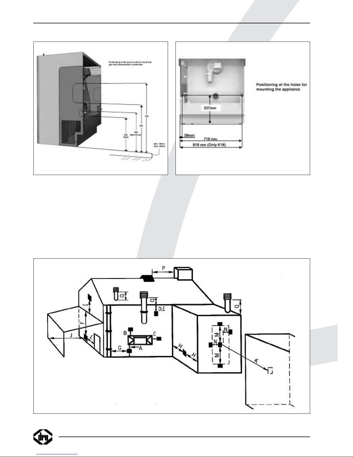
The extended flue can be placed at both the left and right
side of the appliance. For this, special knock-outs have
been placed at both sides, in the casing.
The components for the extended flue will be supplied by
Drugasar upon request.
When supplied, the appliance is set for the use of natural
gas (G20). Upon request, a conversion set for propane
(G31) can be supplied.
2. CE declaration
We hereby declare that the design and construction of
DRU’s gas heating appliance comply with the essential
requirements of the applicable EC directives.
This declaration will lose its validity if adjustments are
made to the appliance, without prior written permission
by DRU.
Product: gas heating appliance with forced convection air
flow
Type: Power Flue
Applicable EEC directives:
90/396/EEC
2006/95/EC
89/336/EEC
Internal measures by the company guarantee that
appliances produced in series comply with the essential
requirements of the prevailing EEC directives and the
standards derived from them.
M.J.M. Gelten
General manager
Dru verwarming B.V.
Postbus 1021, 6920 BA Duiven
Ratio 8, 6921 RW Duiven
www.dru.nl
INSTRUCTIONS FOR INSTALLATION
2
!
Page 5
3. Safety
3.1 General
Caution - Carefully read this chapter on safety,
before you start performing installation
or maintenance work;
- Please observe the general regulations and
the precautions/safety instructions in this
manual.
3.2 Regulations
• Please install the appliance, including the electrical
installation, in accordance with the applicable national,
local and constructional (installation) regulations.
These are included in, for instance:
- Gas Safety (Installation and Use) Regulations;
- B.S. 6891;
- B.S. 5871: Part 1;
- B.S. 5440: Part 1;
- B.S. 5440: Part 2;
- Local Building Regulations;
- I.E.E Wiring Regulations;
- Health and Safety at work
3.3 Precautions / safety instructions during
installation
Carefully observe the following precautions/safety
regulations:
• you should only install and maintain the appliance if you
are a competent installer in the field of gas heating:
• do not make any changes to the appliance;
• only use the flue gas discharge / combustion air supply
material supplied by Drugasar;
• always place the appliance against a wall of incombustible
and heat-resistant material;
• use the wall brackets when mounting the appliance to the
wall. This will guarantee the minimum required distance
of 10 mm from the back wall;
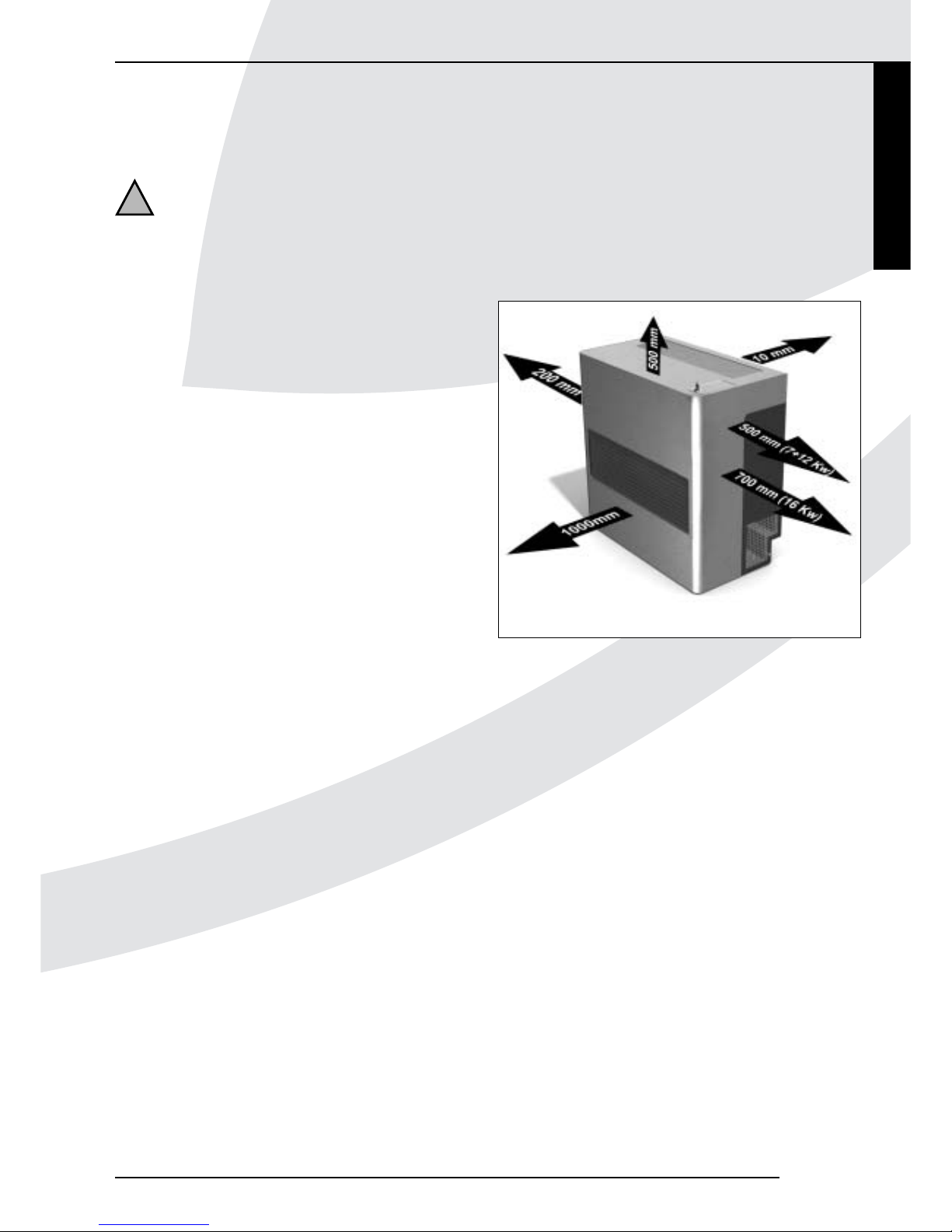
• make sure the appliance has sufficient distance from
other objects and materials (see fig. 1). The free space
surrounding the appliance is necessary for a proper
and safe operation and for accessibility in case of
maintenance;
• make sure there is a free outflow of warm convection air
at the front of the appliance;
• make sure there is a free supply of cold convection air at
both sides of the appliance; Curtains, for example, could
block the inlet as a result of the sucking action of the
convection fan.
• avoid warm convection air from recirculation through the
cold convection air inlet;
• do not cover the appliance and the discharge material
and/or do not wrap it in an insulation blanket or any
other material;
• avoid dirt in gas tubes and connections;
• check the connections for gastightness before using the
appliance;
• do not place and/or use the appliance in a moist
environment;
• place an all-pole switch near the appliance, with a contact
opening of at least 3 mm;
• connect the appliance to earth;
• place electrical connections in such a way that they are
free from the appliance;
• do not ignite the appliance until it is fully installed.
4. Removing the packaging
Note the following items when removing the packaging:
• Check the appliance for damages during transport.
• If necessary, contact Drugasar Service.
• Check whether all parts have been supplied.
In Appendix 1 you can see which parts you should have
after removing the packaging.
• Contact Drugasar Service if you do not have all the parts
after you finished removing the packaging.
• Dispose packaging in accordance with local regulations.
Kamara
INSTRUCTIONS FOR INSTALLATION
!
Fig. 1
3
English
Page 6
5. Installation
Read this manual carefully to ensure a proper and safe
operation of the appliance.
!Caution Install the appliance in the order described in
this chapter.
5.1 Regulations
• Please observe the applicable national, local and
constructional (installation) regulations for both the
appliance and the electric installation.
• Observe the regulations/instructions in this manual.
5.2 Type of gas
The type plate indicates for which type of gas, gas
pressure and for which country this appliance is intended.
The type plate can be found on the left side on the
convection box. You can see it after removing the casing.
The appliance can be converted for usage with propane.
The gas supply pressure should be at least 30 mbar.
For conversion to propane, see section 5.10.
• Check whether the appliance is suitable for the type of gas
and the gas pressure used at the location.
5.3 Gas connection
Caution Avoid dirt in the gas tube and in the
connections.
The following requirements apply to the gas connection:
- use a gas tube with the correct dimensions, so that no
pressure loss can occur;
- the gas tap, if used, should have CE marking;
- you should always be able to reach the gas tap.
5.4 electrical connection
The following requirements apply to the electrical
connection:
- you must place an all-pole switch near the appliance,
with a contact opening of at least 3 mm;
- the required electrical voltage is 230V/50Hz~;
protected with 5A.
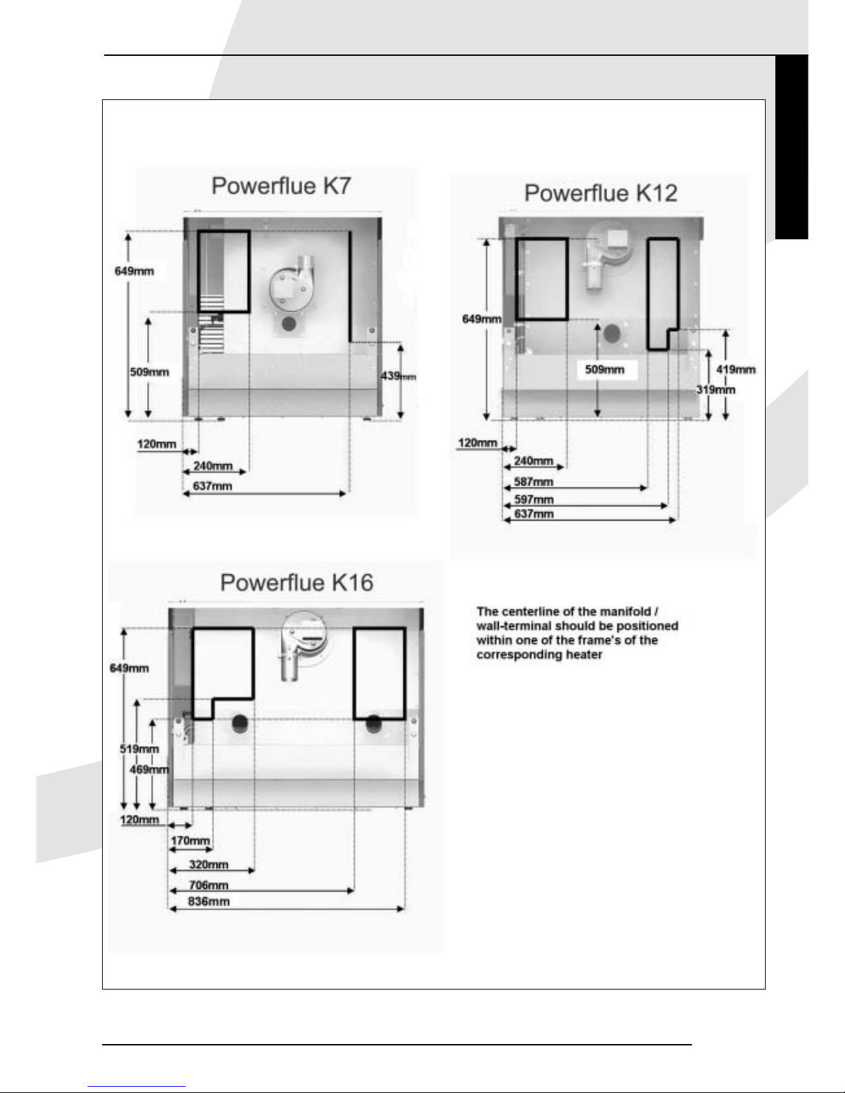
5.5 Wall-terminal and manifold
5.5.1 Position wall-terminal/manifold
Positioning of wall-terminal/manifold directly behind the
appliance. (For further information see chapter 5.7.2)
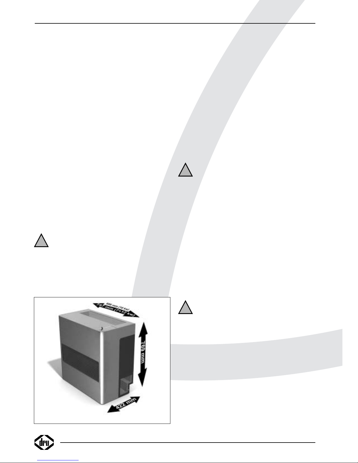
• Determine the location of the appliance; the dimensions
can be found in fig. 1 and 2.
Caution - Make sure the appliance has sufficient
distance from other objects and materials.
The free space surrounding the appliance
is necessary for a proper and safe
operation and for accessibility in case of
maintenance.
- Always place the appliance against a wall of
incombustible and heat-resistant material.
!Tip The manifold has two combustion air supply
connections, see chapter 5.5.2
!Tip Determine the position of the appliance and the
connections by using the dimensions in
fig. 3a and 3b.
For extended flue sample see fig. 8.
• Determine the location of the manifold/wall-terminal.
Caution Use Table 2 to determine the allowed
number of curves in combination with the
length of the discharge system.
!Caution - The bends in the flexible flue gas
discharge tube and the combustion air
supply hose should be as smooth as
possible, to keep the resistance as low
as possible;
- The wall-terminal is suitable for walls with
a thickness up to 400 mm; if necessary,
Drugasar can supply a wall wall-terminal
for walls with a thickness up to 900 mm;
- Take the requirements concerning the
position of the wall-terminal in the outer
wall into consideration, as indicated in
section 5.5.1.1.
- See also chapter 5.7.3, for the extended
flue option.
4
INSTRUCTIONS FOR INSTALLATION
!
Fig. 2
!
!
Page 7
INSTRUCTIONS FOR INSTALLATION
Fig. 3a
Kamara
5
English
Page 8
6
INSTRUCTIONS FOR INSTALLATION
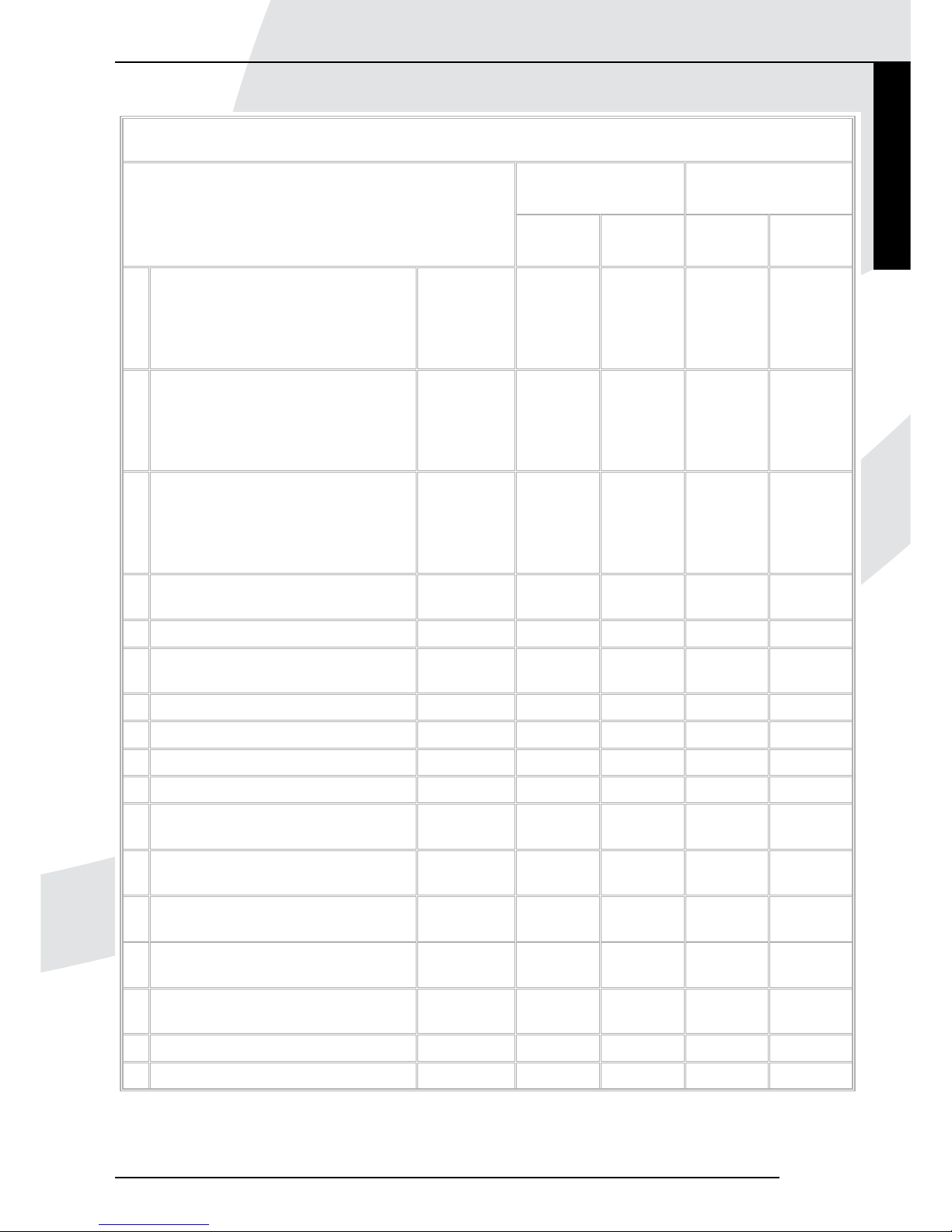
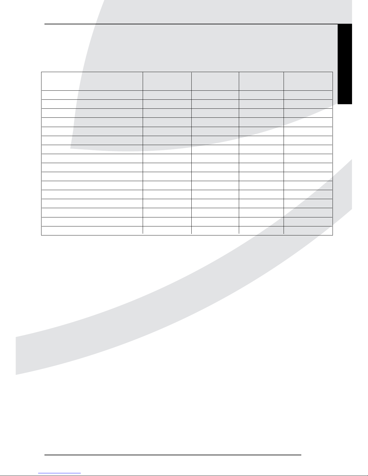
5.5.1.1 Position of wall-terminal in outside wall
The following diagram and related chart are broadly based
around BS5440:Part 1:2000. For additional comments/
applications please refer to this BSI standard directly.
Fig. 3b Fig. 3c
Page 9
INSTRUCTIONS FOR INSTALLATION
Minimum dimensions of flue wall-terminal positions
Balance flues
room sealed
Open flues
Wall-terminal position
Natural
draught
Fanned
draught
Natural
draught
Fanned
draught
A * Directly below an opening, airbrick,
window etc.
0-7kW
>7-14kW
>14-32kW
>32-70kW
300 mm
600 mm
1500 mm
2000 mm
300 mm Not allowed 300 mm
B * Above an opening, airbrick, window
etc.
0-7kW
>7-14kW
>14-32kW
>32-70kW
300 mm
300 mm
300 mm
300 mm
300 mm Not allowed 300 mm
C * Horizontally to an opening, airbrick,
window etc.
0-7kW
>7-14kW
>14-32kW
>32-70kW
300 mm
400 mm
600 mm
600 mm
300 mm Not allowed 300 mm
D Below a gutter or sanitary tube if
combustible material protected.
300 mm 75 mm Not allowed 75 mm
E Below eaves. 300 mm 200 mm Not allowed 200 mm
F Below balconies or open roofed out
buildings.
600 mm 200 mm Not allowed 200 mm
G From a vertical drain or soil tube. 300 mm 150 mm Not allowed 150 mm
H From an internal or external corner. 600 mm 300 mm Not allowed 200 mm
I Above ground or balcony level. 300 mm 300 mm Not allowed 300 mm
J From a surface facing the wall-terminal. 600 mm 600 mm N/A 600 mm
K From another wall-terminal facing the
wall-terminal.
600 mm 1200 mm N/A 1200 mm
L From an opening in the car port into a
dwelling.
1200 mm 1200 mm N/A 1200 mm
M Vertically from a wall-terminal on the
same wall.
1500 mm 1500 mm N/A 1500 mm
N Horizontally from a wall-terminal on the
same wall.
300 mm 300 mm N/A 300 mm
O From a wall on which the wall-terminal
is mounted.
N/A N/A N/A 50 mm
P From a vertical structure on the roof. N/A N/A 600 mm N/A
Q Above intersection with roof. N/A N/A 600 mm 150 mm
Notes: N/A = NOT APPLICAIABLE * In addition, the wall-terminal should not be nearer than 150mm (fan draught) or 300mm (natural draught) to an
opening in the building fabric formed for the purpose of accommodating a built-in element such as a window frame. Separation distances are linked to the
rated heat inputs as shown.
Kamara
7
English
Page 10
5.5.2 Installation of wall-terminal and manifold
Follow the procedure below when installing the wallterminal and manifold:
• Drill a hole in the wall, with a diameter of 105 mm.
• Drill 3 holes in the wall from the outside, for mounting
the wall-terminal.
!Caution - Place the wall terminal with the groove/
folded seam at the top;
• Glue the sealing/gasket of the wall-terminal to the flange.
• Temporarily mount the wall-terminal from the outside.
• Slide the manifold from the inside as far as possible onto
the concentric tubes of the wall-terminal.
• Determine the distance between manifold and wall.
• Unscrew the wall-terminal.
• Cut the wall-terminal to size.
• Mount the wall-terminal for the final time.
• Determine in which angle the manifold should be placed.
• Apply a sufficient amount of heat-resistant sealant to the
outside of the galvanized steel combustion air supply tube.
• Apply a film of heat resistant sealant to the inside of the
aluminium flue gas discharge tube.
• Place the sealing/gasket of the manifold between wall and
manifold.
!Tip For the manifold, you can choose between two
combustion air supply connections.
• Mount the manifold in the correct position.
• Drill 3 holes in the wall for mounting the manifold.
• Mount the manifold with the screws and washers supplied.
• If necessary, apply a wall-terminal guard.
• Place the wall-terminal guard centrally over the wallterminal.
5.6 Placing the appliance
Place the appliance as follows:
Caution - Do not make any changes to the
appliance;
- Do not cover the appliance and the
discharge material and/or do not wrap
it in an insulation blanket or any other
material;
- Mount the appliance to the wall using
the wall brackets; this will guarantee the
minimum required distance of 10 mm
from the back wall;
- Make sure there is a free outflow of
warm convection air at the front of the
appliance;
- Make sure there is a free supply of
cold convection air at both sides of the
appliance. Curtains, for example, could
block the inlet as a result of the sucking
action of the convection fan.
- Avoid that warm convection air can
recirculate through the cold convection
air inlet.
!Tip - Prevent construction grid/drill material from
contaminating the appliance;
- Only mount the casing, after performing the final
check in section 7.
• Provide a gas connection at the location. For details, see
section 5.3.
• Provide an electrical connection at the location. For
details, see section 5.4.
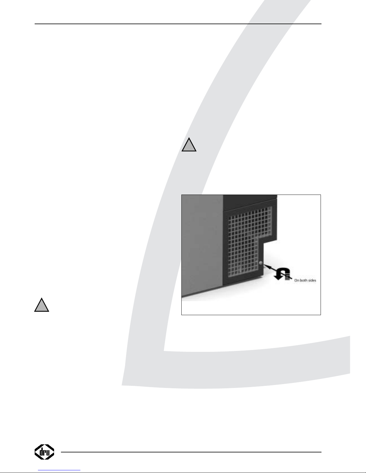
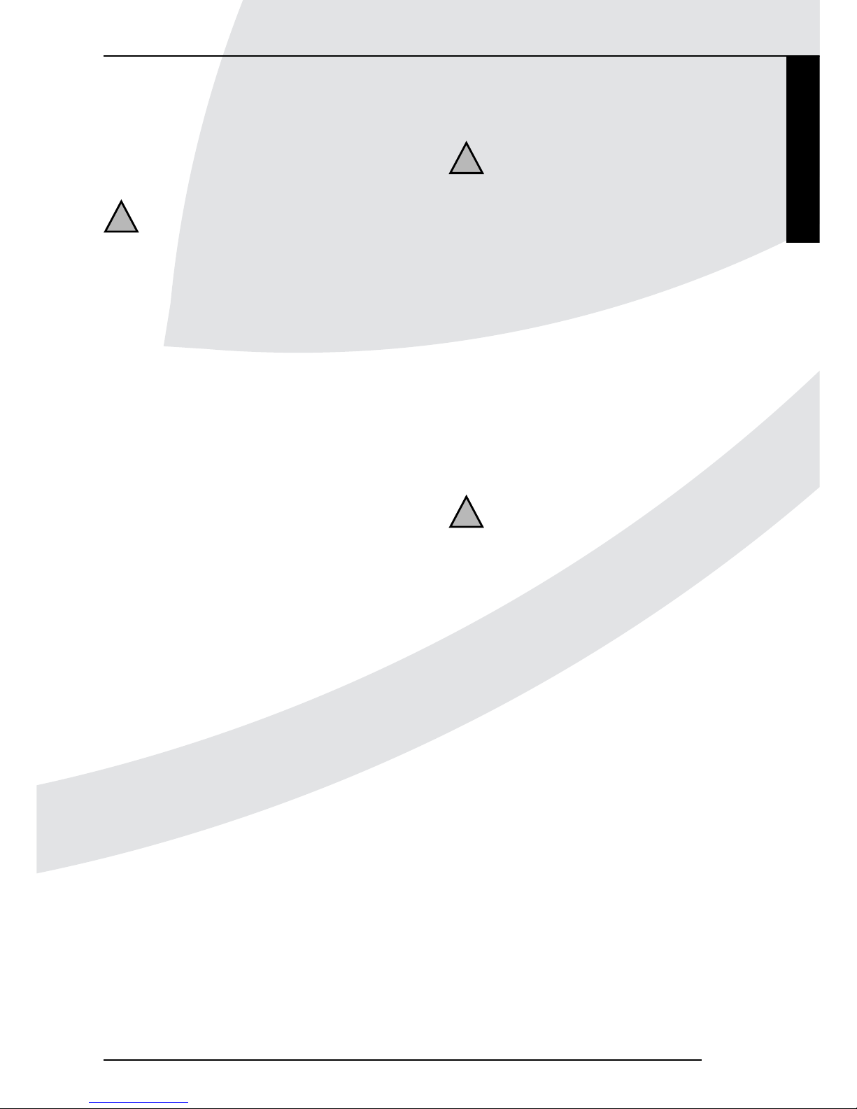
• Remove the casing:
- Unscrew the screws at both sides of the casing
(see fig. 4);
- Lift the casing appr. 1 cm and slide/lift the casing to the
front.
Caution Avoid damaging the wiring when taking off
the mantel.
• Place the appliance on its destined location.
• Drill holes for mounting the appliance.
• Attach the appliance to the wall, using the supplied plugs,
washers and screws.
5.7 Flue gas discharge / combustion air supply
system
5.7.1 Construction
For the 7kW and 12kW Power Flue, the maximum length
of the discharge tubes (vertical and horizontal) is 10
meters when using a maximum of 2 bends of 90º; when
3 bends of 90º will be used, the total maximum length of
the discharge system is 6 meters, and when 4 bends of 90º
will be used, the maximum length is 2 meters.
For the 16 kW Power Flue, the maximum length of the
discharge tubes (vertical and horizontal) is 3 meters, with
a maximum of 1 bend of 90°.
Depending on the construction, the appliance is set by
means of a restriction.
INSTRUCTIONS FOR INSTALLATION
8
!
!
Fig. 4
Page 11
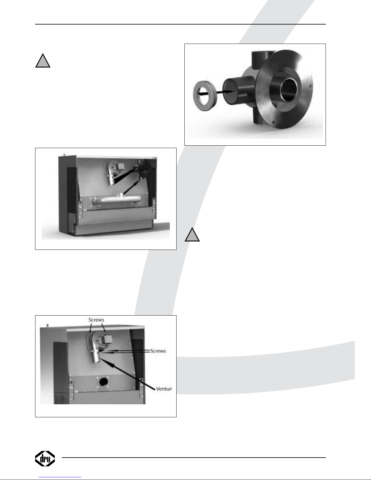
For the 7kW version, the restrictor (supplied) is mounted
on the combustion fan. Please note the restrictor is part
of the venturi on the combustion fan.
For the 7kW Power Flue, the restriction is 22.5 mm when
using natural gas and propane.
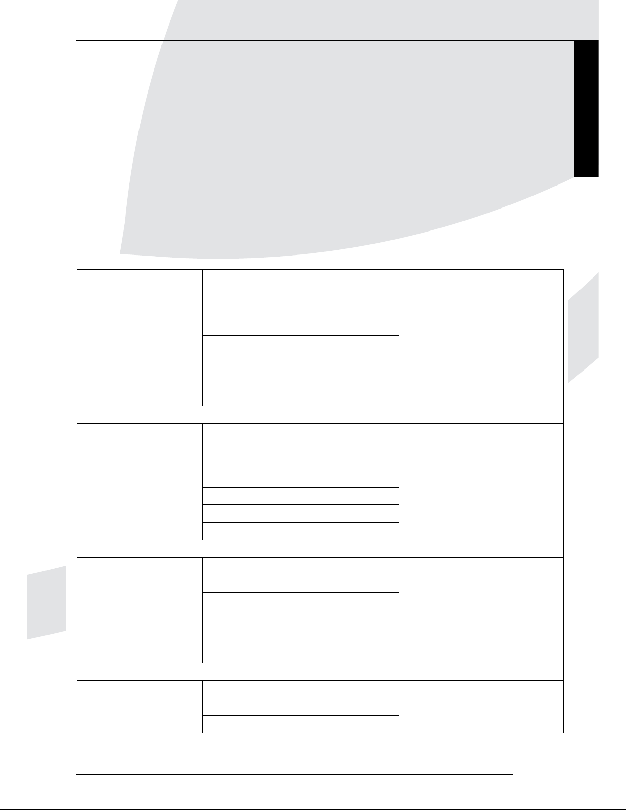
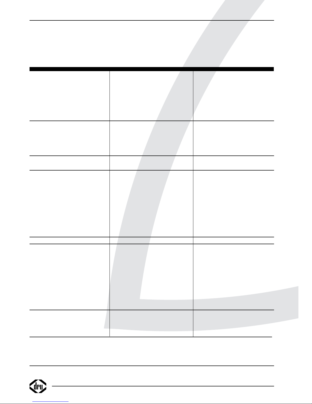
In Table 2 below, you can see the settings of the
restriction in relation to the construction of the discharge
system and the type of gas that is used
At the 12kW and 16kW versions, the restriction – if
necessary – will be placed in the flue gas discharge
connection of the manifold, with a heat-resistant sealant
(see fig. 7).
At the 12kW Power Flue, a restriction is only required if
the appliance is connected directly to the wall-terminal.
When using natural gas, the restriction will be 36 mm, and
when using propane 45 mm.
For the 16kW Power Flue, a 45 mm restriction is also
only required in case of a direct connection to the wallterminal. This value applies to the usage of both natural
gas and propane.
INSTRUCTIONS FOR INSTALLATION
Type Type of gas Number of
90º bends
tube length
(meter)
Restriction
(mm)
Remarks
7kW G20/G31 0 0 22,5
Direct connection to wall-terminal
0 1-10 22,5
1 1-10 22,5
Restriction is a fixed part
2 1-10 22,5
of venturi tube
3 1-6 22,5
4 1-2 22,5
12kW G20 0 0 36
Direct connection to wall wallterminal
0 1-10 none
1 1-10 none
2 1-10 none
3 1-6 none
4 1-2 none
G31 0 0 45
Direct connection to wall-terminal
0 1-10 none
1 1-10 none
2 1-10 none
3 1-6 none
4 1-2 none
16kW G20/G31 0 0 45
Direct connection to wall-terminal
0 1-3 none
1 1-3 none
Table 2: Relations between restriction, discharge system construction and type of gas
Kamara
9
English
Page 12
5.7.2 Placing standard flue kit
Caution Only use the standard flue kit supplied by
Drugasar.
!Caution - The cutting sides of the flexible
combustion gas discharge tube are sharp;
- The bends in the flexible flue gas discharge
tube and the combustion air supply hose
should be as smooth as possible, to keep
the resistance as low as possible;
- The 16kW Power Flue has 2 combustion
air supply connections on the appliance.
They should both be connected and be
combined by means of a T-joint (see fig.
5).
Follow the steps below for mounting the standard flue kit:
• Make sure the flexible combustion gas discharge tube has
the right dimensions
• On one side of the flexible combustion gas discharge tube,
apply the heat-resistant sealant in the grooves on the
inside.
• Add the hoseclamps
• Slide the flexible discharge tube onto the venturi tube that
is connected to the combustion fan (see fig. 6).
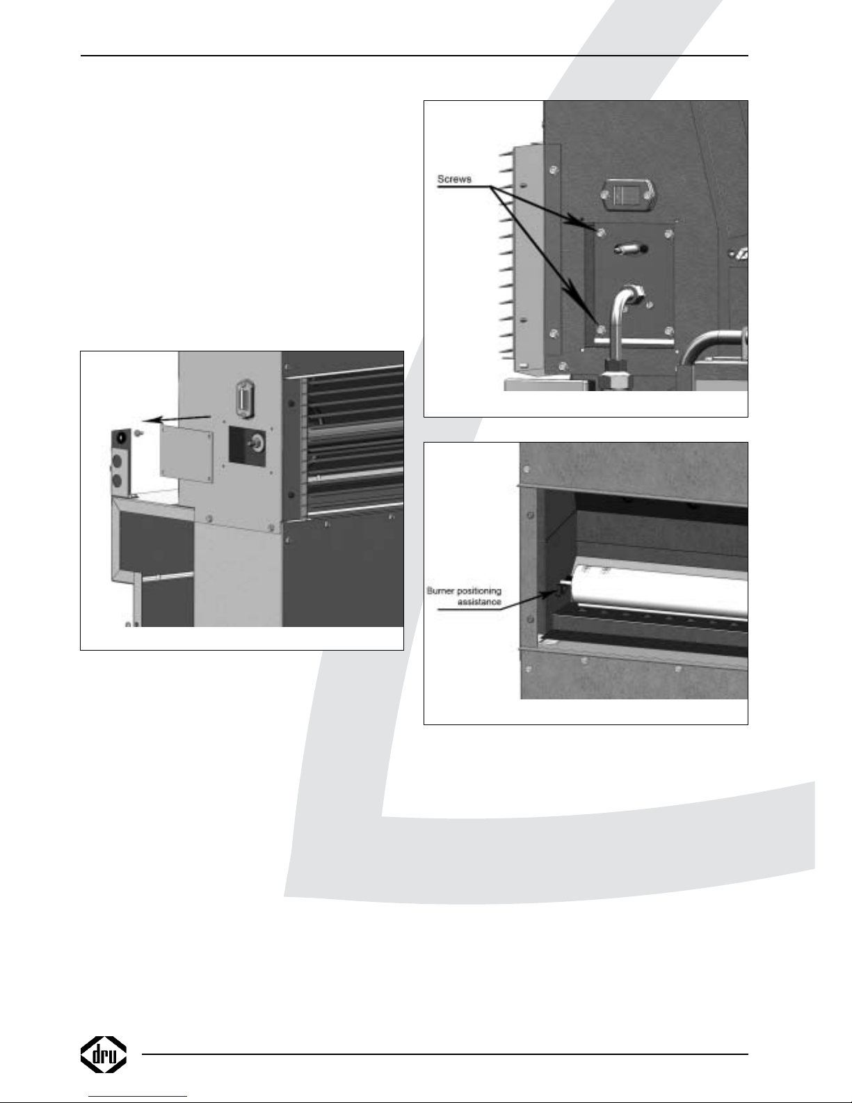
• If necessary, attach the restriction in the flue gas discharge
connection of the manifold with the supplied heat resistant
sealant; see Table 2; see fig. 7.
• Connect the flexible flue tube to the manifold in the same
way as described above.
• Fasten the hoseclamps.
• Make sure the flexible combustion air supply hose has the
right dimensions.
• Connect this hose to the appliance and the manifold by
using the supplied standard hose clamps.
• Seal the unused combustion air supply connection on the
manifold using the supplied silicon plug.
5.7.3 Placing the extended flue
Caution - Mount the flue tubes sloping towards the
appliance.
- Place a condensate drain with U-trap in
the rigid part of the discharge system, if
the total length exceeds 3 meters;
- Install the condensate drain within a
distance from the appliance of 3 meters,
but preferably as close as possible to the
appliance.
!Caution - Connect rigid tube pieces/bends to the
manifold. You may only use the flexible
discharge tube/air supply hose on the
appliance;
- Prevent construction grid/drill material
from contaminating the appliance.
!Tip The extended flue can optionally be
connected to the left or right side of the
appliance.
Proceed as follows, when installing the extended flue
(see fig. 8):
• Mount the required brackets for the rigid aluminium flue
gas discharge tube and the rigid aluminium combustion air
supply tube.
• See also fig. 3b for possible position of the tubes.
• Mount the tubes and any bends of rigid aluminium.
• Connect the flexible discharge tube/air supply hose as
described above for the standard flue kit, section 5.7.2
INSTRUCTIONS FOR INSTALLATION
10
!
Fig. 5
Fig. 6
Fig. 7
!
Page 13
5.8 Connecting gas
Use the following procedure when connecting the gas; for
this, also see section 5.3, Gas connection:
!Tip The gas connection can optionally be connected
to the left or right side of the appliance.
• If necessary, blow through the gas tube.
• Connect the gas tube with gas tap to the 15mm tube on
the appliance.
!Caution Do not twist the gas tap when connecting the
gas tube.
• Bleed the gas tube.
5.9 Converting to propane
If necessary, the appliance can be converted to use of
propane.
For this, the injector has to be replaced and the burner
pressure has to be adjusted.
Follow the procedure described below:
Caution - Close the gas tap;
- Switch off the all-pole switch;
- Remove the main fuse.
• Remove the ignition cap.
• Remove the sealing surrounding the electrode pen.
• Unscrew the 4 screws of the cover plates around the gas
tube and ignition pen (see fig. 9).
• Remove the cover plates.
• Unscrew the brass union of the gas tube under the
electrode pen.
• Unscrew the brass union of the gas tube on the gas
control valve.
!Caution Make sure the thread reducing bushes on the
gas control valve do not rotate as well.
• Remove the gas tube from the appliance.
• Remove the injector holder.
• Replace the injector by the propane injector.
• Reassemble everything in opposite order.
• Adjust the burner pressure for propane, using the test
point and the adjusting screw; see fig. 10. Appendix 3
contains the required gas pressure for the various versions
of the appliance.
!Caution When checking/adjusting the burner pressure,
the appliance should be in operation for at least
10 min.
!Tip The adjusting screw is located behind the cover
screw.
5.10 Connecting electrical equipment
Caution The appliance must be earthed.
!Tip The electrical connection can optionally
be made at the left or right side of the
appliance.
Standard, the appliance is designed for use of an external
clock and/or thermostat through a 5 wire cable; for this,
see the electrical diagram in appendix 2.
When the external clock and/or thermostat is not used,
the relay can be bridged by connecting the contacts.
Or connect 1 N and 2 L
• Connect the electric wiring in accordance to the diagram.
INSTRUCTIONS FOR INSTALLATION
Fig. 8
!
Fig. 9
!
Kamara
11
English
Page 14
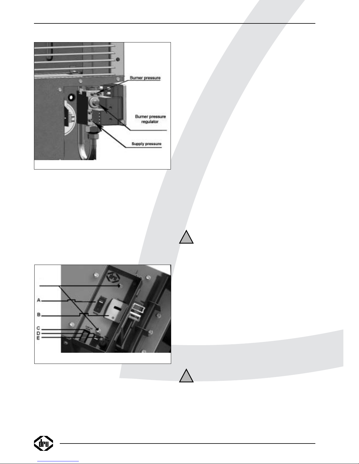
6. Operating the appliance
6.1 Control panel
The control panel is located under the cover at the top of
the appliance.
The cover is provided with a lock.
On the panel you will find (see fig. 11)
a) summer/winter switch;
b) thermostat;
c) lock-out mode;
d) reset button;
e) fuse.
sub a)
“0” position
In the position “0”, the appliance is switched off
winter position
In the winter position, you have 2 options:
1) The appliance is controlled by an external clock and/or
thermostat;
2) The appliance is only controlled by the internal
thermostat.
summer position
In the summer position the appliance will operate
independently from an external clock and/or thermostat.
In this position, only convection air (= surrounding air) is
circulated.
Sub b)
The (internal) thermostat can be set between 5 ºC
and 35 ºC.
The green led of the thermostat will light if the appliance
is switched on and the thermostat is “not requesting”.
The red led will light if the appliance is switched on and
the thermostat is “requesting”.
Sub c)
In case of a malfunction, the red lamp of the lock-out
mode will light.
Sub d)
In case of a malfunction, the appliance can be reset by
using the reset button.
6.2 Switching on the appliance for heating
• Set the external clock and/or thermostat, if present.
• Set the thermostat to the required temperature.
• Set the switch to the winter position.
Caution About approximately 30 seconds after
igniting the burner, the convection fan
should switch on.
The louvre openings will release warm air.
6.3 Switching on the appliance for air
circulation
• Set the switch to the summer position.
The appliance will continuously circulate convection air
(= surrounding air).
6.4 Switching off the appliance
• Set the switch to the “0” position.
7. Final check
To check that the appliance is operating correctly and
safely, you must proceed as follows before the appliance is
used.
7.1 Gastightness
Caution All connections must be gastight.
!Caution The supply pressure to the gas control
valve cannot exceed 50 mbar.
• Check the connections for gastightness.
• Make the connections gastight, if necessary.
INSTRUCTIONS FOR INSTALLATION
12
!
!
Fig. 11
SCREWS
(behind cover screw)
Fig. 10
test point
test point
Page 15
7.2 Gas pressure / supply-pressure
The burner pressure is set at the factory for the use of
natural gas; see type plate. It is not necessary to check the
burner pressure after installation.
The supply-pressure in house installations should be
checked, as they can vary.
Caution - After conversion to propane, the
burner pressure must be checked and if
necessary adjusted.
- After maintenance work the burner
pressure must be checked, irrespective
of whether you are using natural gas or
propane, and adjusted if necessary.
Proceed as follows; see fig. 10:
• Check the supply-pressure.
• Contact the gas company if the supply-pressure is not
correct.
• If necessary, check the burner pressure; see Appendix 3
for the required burner pressure.
!Caution When checking/adjusting the burner
pressure, the appliance should be in
operation for at least 10 min.
• Adjust the burner pressure, if necessary.
!Tip The adjusting screw is located behind the
cover screw.
7.3 Ignition burner
For igniting the burner, see section 6.2.
!Caution After 5 ignition attempts, the appliance
will enter the lock-out mode.
• Ignite the burner
• Check if the convection fan is working.
• See in Table 3, Diagnosis of malfunctions, if the convection
fan does not work and/or the burner does not ignite.
7.4 Flame picture
• Check the flame picture.
If the flame picture is unacceptable, do the following:
• Check whether the flue gas discharge and/or air supply are
blocked.
• If necessary, remedy the blockage.
7.5 Flue gas discharge / combustion air supply
• Check the flue gas discharge and the combustion air
supply for gastightness.
• Check whether the flue gas discharge and/or combustion
air supply are lying free from, for example, electrical
wiring, the convection housing.
• If a failure occurs, correct it.
8. Remove / replace the outer casing
The casing is removed as follows:
Caution Avoid damaging the wiring when taking off
the casing.
• Take out the screws at both sides of the casing
(see fig. 4);
• Lift the casing appr. 1 cm and slide/lift the casing to the
front.
Replace in reverse order of the removal procedure.
!Tip If the casing is placed for the first time,
the knock-outs concerned must be
removed first.
!Caution Make sure that the locating bracket fall
into the intended notches.
9. Maintenance
Once a year the appliance should be checked, cleaned and,
if necessary, repaired by a competent installer in the field
of gas heating.
Check that the appliance is operating correctly and safely.
!Caution - Close the gas tap;
- Switch off the all-pole switch;
- Remove the main fuse
during maintenance
work;
- Check the gastightness after repair.
9.1 Maintenance instructions
Perform maintenance work as described below:
• Remove the casing, see section 8.
• Clean the filters as follows:
- Suck/blow the filter clean.
If the filter is not sufficiently clean, you must
- Unscrew the 4 screws;
- Remove the filter;
- Flush the filter with water and clean it with a soft brush.
• Perform the procedure above for both filters.
• Check the fans for contamination and clean, if necessary.
• Check if the fans are operating correctly and replace them
if necessary; see section 9.2.
• Inspect the flue gas discharge / combustion air supply
system and, if necessary, replace the flexible flue gas
discharge tube.
• If necessary, clean the burner and the injector. For
removing the burner, see section 9.2.1.
• Perform a check as described in chapter 7.
9.2 Replacing parts
Below you will see how the various parts can be replaced.
• Remove the casing, for this see section 8.
INSTRUCTIONS FOR INSTALLATION
!
!
!
Kamara
13
English
Page 16
9.2.1 Burner
!Caution Only for Power Flue 7kW
- Remove the cover plate to the left on the
convection housing; see fig. 12;
- Unscrew the nut;
- Remove the washer and the sealing ring.
For all appliances, continue as described below:
• Remove the ignition cap.
• Remove the sealing surrounding the electrode pen.
• Take out the 4 screws of the cover plates around the gas
tube and the ignition pen (see fig. 9).
• Remove the cover plates.
• Unscrew the brass union of the gas tube under the
ignition pen.
• Unscrew the brass union of the gas tube on the gas
control valve.
!Caution Make sure the thread reducing bushes on the
gas control valve do not rotate as well.
• Remove the gas tube from the appliance.
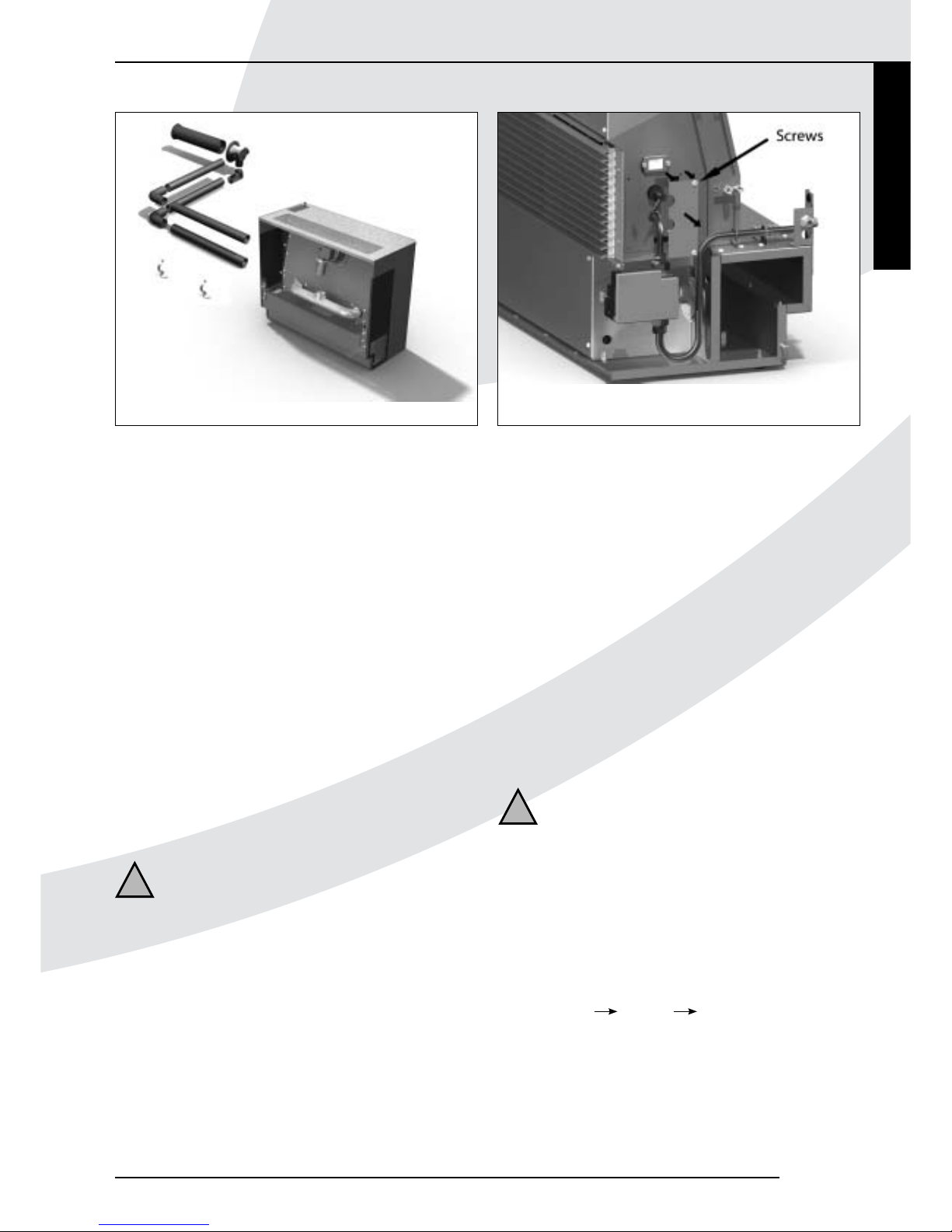
• Take out the 4 screws of the burner; see fig 13.
• Carefully remove the burner tube from the combustion
chamber.
• Place the new burner in reverse order.
!Caution Only for Power Flue 12kW and 16 kW:
- Place the pin at the end of the burner tube
on the V; see fig. 14;
- Position the burner tube in such a way, that
the pin drops in the hole.
• Check supply pressure.
• Check the burner pressure and, if necessary, adjust it as
described in section 7.2
9.2.2 Electrode pen
• Remove the ignition cap.
• Remove the sealing surrounding the electrode pen
• Take out the 4 screws of the cover plates around the gas
tube and the electrode pen (see fig. 9).
• Remove the cover plates.
• Take out the 2 screws of the mounting plate.
• Remove the electrode pen.
• Place the new electrode pen in reverse order
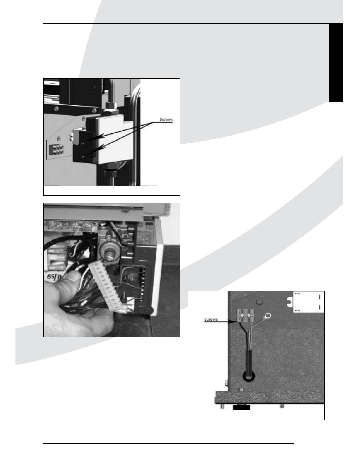
9.2.3 Automatic ignition sequence
• Take out the 2 screws of the cover on the automatic
ignition sequence (see fig. 15)
(the upper screw is used to fix the automatic burner to
the gas control valve; the lower screw fixes the cover)
• Remove the cover.
• Pull the 2 connectors out of the automatic ignition
sequence (see fig. 16).
INSTRUCTIONS FOR INSTALLATION
Fig. 12
Fig. 13
Fig. 14
14
Page 17
• Pull out the ignition cable.
• Remove the automatic ignition sequence by pulling it to
the front side of the appliance.
• Place the new automatic ignition sequence in reverse
order.
!Caution - Place the automatic ignition sequence in such
a way, that the connector is connected again;
- Prevent wiring from getting stuck under the
cover.
9.2.4 Gas control valve
• Remove the automatic ignition sequence, as described
above in section 9.2.3.
• Remove the ignition cap.
• Remove the sealing surrounding the electrode pen
• Take out the 4 screws of the cover plates around the gas
tube and the electrode pen (see fig. 9).
• Remove the cover plates.
• Unscrew the brass union of the gas tube under the
electrode pen.
• Unscrew the brass union of the gas tube on the gas
control valve.
• Disconnect the earth wire.
• Remove the gas control valve.
• Disconnect the thread reducing bushes (top and bottom
side) from the gas control valve.
• Connect the thread reducing bushes to the new gas
control valve.
!Caution Use new sealing rings when mounting the
thread reducing bushes.
• Place the gas control valve in opposite order.
• Adjust the burner pressure as described in section 7.2
• Perform a final check as described in chapter 7
9.2.5 Convection fan
• On the appliance, disconnect the electric wiring of the
convection fan (see fig. 17).
• Take out the screws from the lower cover plate at the
front of the appliance.
• Remove this plate.
• Remove the electric cable from the cable clips.
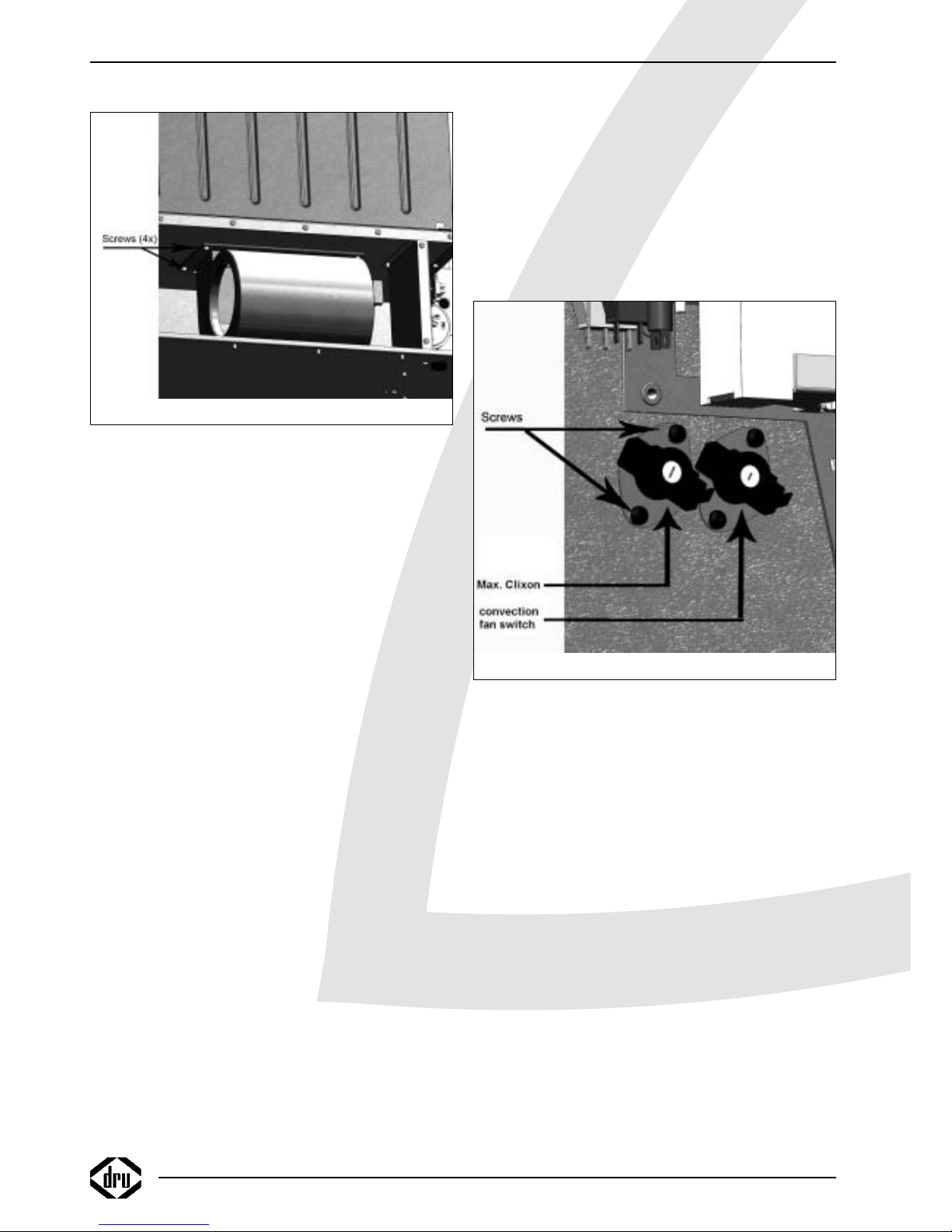
• Take out the 4 socket cap screws that are used to mount
the fan (see fig. 18).
• Remove the fan.
• Place the new fan in reverse order
Kamara
INSTRUCTIONS FOR INSTALLATION
15
Fig. 15
Fig. 16
Fig. 17
English
Page 18
9.2.6 Combustion fan
• Take out the clamp of the flexible flue gas discharge tube.
• Remove the flexible flue gas discharge tube.
• Take out the clamp that is used to mount the venturi tube
on the fan.
• Remove the venturi tube.
• Disconnect the air hose from the fan (positive measuring
point).
• Disconnect the electric wiring from the fan.
• Take out the 4 screws of the assembly plate (see fig. 6).
• Remove the fan assembly.
• Take out the 3 screws connecting the fan to the assembly
plate.
• Remove the fan
• Place the new fan in reverse order.
!Caution - Using new gaskets;
- Fix the venturi tube using heat-resistant
sealant and the clamp;
- Also fix the flexible discharge tube using the
sealant and the clamp;
- Make sure that the wiring is lying free from
the convection box and the fan house.
9.2.7 Temperature limit switch
(maximum thermostat)
• Disconnect the fast-on connections of the electrical
connection.
• Take out the 2 screws of the mounting plate (see fig. 19 of
Power Flue 12/16kW).
!Tip Only for Power Flue 7kW:
- Take out the 2 screws on the control panel
(see fig. 11);
- Slightly lift the panel;
- Take out the upper screw of the mounting
plate.
• Remove the switch.
• Place the new switch in reverse order.
!Caution For the Power Flue 16kW, 2 distance bushes
and a gasket are used.
9.2.8 Convection fan switch
• Disconnect the fast-on connections of the electrical
connection.
• Take out the 2 screws on the mounting plate (see fig. 19);
!Tip Only for Power Flue 7kW:
- Take out the 2 screws on the control panel
(see fig. 11);
- Slightly lift the panel;
- Take out the upper screw of the mounting
plate.
• Remove the switch.
• Place the new switch in reverse order.
9.2.9 Thermostat
• Take out the 2 screws on the control panel (see fig. 11).
• Slightly lift the control panel.
• Remove the thermostat.
• Disconnect the wiring.
• Place the new thermostat in reverse order.
INSTRUCTIONS FOR INSTALLATION
16
Fig. 18
Fig. 19
Page 19
Kamara
INSTRUCTIONS FOR INSTALLATION
17
9.2.10 NTC temperature sensor
The temperature sensor is located in the convection air
inlet, at the filter on the right side of the appliance.
• Take out the 2 screws on the control panel.
• Lift the control panel and slide it slightly to the side.
• Disconnect the wires of the temperature sensor on the
thermostat.
• Remove the temperature sensor.
• Place the new temperature sensor in reverse order.
9.2.11 Air pressure switch
• Take out the screws.
!Tip You can reach the screws through the
convection air inlet on the right side
• Disconnect the hoses.
• Disconnect the wiring.
!Caution - Remember how the hoses are connected;
- Remember how the wiring is connected;
- The setpoint of the air pressure switch
depends on the type of appliance.
• Remove the air pressure switch.
• Place the new air pressure switch in reverse order.
10. Delivery
You must explain the user how to operate the appliance.
You should instruct the user on using the appliance for
the first time, its operation and annual maintenance.
Caution - Tell the user to close the gas tap
immediately and switch off the all-pole
switch in case of malfunctions/bad
performance and contact the installer in
order to prevent dangerous situations;
- Indicate the location of the gas tap;
- Indicate the location of the all-pole switch.
• Instruct the user on how the appliance works.
• Remind the user that the appliance requires annual
maintenance.
• Give the user manual and installation manual to the user
(the installation manual should be kept near the appliance).
!
English
Page 20
18
TROUBLESHOOTING GUIDE
1. Set clock properly
2. Set thermostat correctly
3. Set the switch in the correct position
4. Switch on the all-pole switch
5. - First find the cause of the defective fuse
and remedy it
- Then replace the main fuse
6. - First find the cause of the defective fuse
and remedy it
- Then replace the appliance fuse
1. Clean filters
2. Check burner pressure;
If necessary, correct burner pressure
3. Check convection air circuit:
If necessary, unblock it.
4. Clean fan
5. Replace fan
1. Check gas supply
If necessary, repair gas supply
1. Replace the ignition cable
2. Replace the electrode pen
3. Check connections air pressure switch:
- Connect properly
- If necessary, replace the air pressure
switch
4. Replace fan
5. Unblock
6. Check the electric connections:
improve connections where necessary
Note: the automatic burner is phase
sensitive
7. Gap between electrode and burner should
be between 5 and 6 mm
7. Replace automatic burner
1. Set summer / winter switch to summer
position.
If convection fan switches on:
- Check and, if necessary, replace the
wiring
- If necessary, replace switch
2. Set summer / winter switch to summer
position
Convection fan also does not work in
summer position:
- Check and, if necessary, replace the
wiring
- If necessary, replace the fan
1. Check if life and neurtal are in the correct
possition, if necessary change
2. Check flue and terminal, if necessary
remove blockage
A. Appliance does not react/work
B. Temperature limit switch
(clixon 120 ºC) interferes
C. No gas
D. No ignition (spark)
E. Convection fan does not switch on
F. Burner ignite, but goes out in a few
seconds
1. Clock not set properly
2. Thermostat set incorrectly
3. Summer / winter switch in incorrect
position
4. All-pole switch switched off
5. Main fuse defective
6. Appliance fuse defective (on control
panel)
1. Very contaminated filters
2. Appliance overloaded
3. Convection air circuit blocked
4. Convection fan very dirty
5. Convection fan defective
1. Gas supply interrupted/stopped.
1. Ignition cable damaged
2. Electrode pen corroded
3. Air pressure switch does not function
4. Combustion gas fan very dirty
5. Flue gas discharge / combustion air supply
system blocked
6. Electric connections incorrect
7. Gap electrode / burner to small or to big
7. Automatic burner defective
1. Convection fan switch defective
2. Convection fan defective
1. Reversed plolarity
2. Partial or complete flue blockage
OBSERVED PROBLEM: POSSIBLE CAUSE: REMEDY:
11. MALFUNCTIONS
In the following table you will find an overview of malfunctions that might occur, the possible causes and the remedies.
Table 3 diagnosis of malfunctions
Page 21
19
Kamara
APPENDIX 1
Appendix 1 Parts included with the delivery
In the following table you can find the parts that are supplied with the appliance.
PART K7 K12 K16 ORDERNR.
Installation manual 1x 1x 1x 95762501
User manual 1x 1x 1x 95762401
Sealant 1x 1x 1x 907918
Standard hose clamp 50-70mm 2x 2x 2x 806656
Hose clamp (64-67mm) 2x 2x 2x 806763
Screws 8x 8x 8x 519456
Plugs 8x 8x 8x 929964
Washers 2x 2x 2x 525015
Exhaust hose I=600 St. Steel 1x 1x 1x 24124
Air inlet hose L=600mm Alu 1x 1x 1x 24126
Cable gland 1x 1x 1x 806695
Wall-terminal 1x 1x 1x 24115
Manifold 1x 1x 1x 806643
Restriction only k12 n.a 1x n.a. 806646
Restriction only k16 n.a. n.a. 1x 806647
Set of 2 lock keys 1x 1x 1x 806511
Silicon plug 1x 1x 1x 806818
English
Page 22

20
APPENDIX 2 ELECTRIC WIRING DIAGRAM
Appendix 2 Electric wiring diagram
white
red
black
5 6 7 8
24.1
23.1
25.1
25
A111 10 9 8 7 6 5 3 2 1
14 13
Page 23

Kamara
APPENDIX 3 TECHNICAL DATA APPENDIX 4 PARTS
21
Appendix 3 Technical data
In the following table you can find the technical data.
Type 7kW 12kW 16kW
Type of gas G20 G31 G20 G31 G20 G31
Burner pressure mbar 13.4 26 17.9 28.9 18.7 29
Nom. load (Hs) kW 8.4 8.3 14.3 13.9 19.6 18.8
Nom. load (Hi) kW 7.6 7.6 12.9 12.8 17.6 17.4
Nom. output kW 7 7 12 11.8 16 15.7
Consumption L/h 785 305 1360 517 1875 704
Burner injector mm 2.25 1.55 2.7 1.9 3.15 2.25
Efficiency class 1 1 1 1 1 1
Appendix 4 Parts
Parts can be ordered through www.drugasar.co.uk
POWER FLUE
K7 230 - 240 Vac 50 Hz Rated power 140 W IP 20
K12 230 - 240 Vac 50 Hz Rated power 140 W IP 20
K16 230 - 240 Vac 50 Hz Rated power 155 W IP 20
English
Page 24

Page 25

INHOUD
Woord vooraf .......................................................................... 24
1. Inleiding ............................................................................ 24
2. CE-verklaring .................................................................. 24
3. VEILIGHEID .................................................................... 25
3.1 Algemeen ......................................................................... 25
3.2 Voorschriften.................................................................. 25
3.3 Voorzorgsmaatregelen / veiligheidsinstructies bij
installatie ......................................................................... 25
4. Uitpakken ........................................................................ 25
5. Installatie .......................................................................... 26
5.1 Voorschriften.................................................................. 26
5.2 Gassoort .......................................................................... 26
5.3 Gasaansluiting ................................................................. 26
5.4 Elektrische aansluiting ................................................. 26
5.5 Geveldoorvoer en verdeelstuk .................................. 26
5.6 Plaatsen van het toestel ............................................... 30
5.7 Verbrandingsgasafvoer- /
verbrandingsluchttoevoersysteem ........................... 30
5.8 Gas aansluiten ................................................................ 33
5.9 Ombouwen naar propaan ........................................... 33
5.10 Elektrische apparatuur aansluiten ..............................33
6. Bedienen van het toestel ............................................ 34
6.1 Bedieningspaneel ............................................................ 34
6.2 Toestel inschakelen voor verwarming ..................... 34
6.3 Toestel inschakelen voor luchtcirculatie ................. 34
6.4 Uitschakelen toestel ..................................................... 34
7. Eindcontrole ................................................................... 34
7.1 Gasdichtheid ................................................................... 34
7.2 Gasdruk / toevoerdruk ................................................ 34
7.3 Ontsteken van de brander .......................................... 35
7.4 Vlambeeld ........................................................................ 35
7.5 Verbrandingsgasafvoer/verbrandingsluchttoevoer . 35
8. Buitenbehuizing verwijderen / vervangen ................ 35
9. Onderhoud ..................................................................... 35
9.1 Aanwijzingen voor onderhoud ................................... 35
9.2 Onderdelen vervangen ................................................. 35
10. Oplevering ....................................................................... 39
11. Storingen ......................................................................... 40
Bijlage 1 Meegeleverde onderdelen ..................................41
Bijlage 2 Schema elektrische bedrading ..........................42
Bijlage 3 Technische gegevens ............................................43
Bijlage 4 Onderdelen ...........................................................43
Nederlands
Kamara
INHOUD
23
Page 26

Woord vooraf
Als fabrikant van gasverwarmingstoestellen ontwikkelt en
produceert DRU producten volgens de hoogst mogelijke
kwaliteits-, prestatie- en veiligheidseisen. De gebruiker kan
hierdoor rekenen op jarenlang gebruiksplezier.
Dit toestel heeft een CE merk; het voldoet daarmee aan
de essentiële eisen van de Europese Gastoestellenrichtlijn.
Als installateur dient u vakbekwaam te zijn op het gebied
van gasverwarming.
Bij het toestel worden twee handleidingen geleverd: de
installatiehandleiding en de gebruikershandleiding. De
installatiehandleiding geeft u de informatie die u nodig hebt
om het toestel zo te installeren dat het goed en veilig
functioneert.
Deze handleiding schenkt aandacht aan de installatie
van het toestel en de daarbij geldende voorschriften.
Daarnaast treft u technische gegevens van het toestel aan
en informatie over onderhoud, eventueel optredende
storingen en de mogelijke oorzaak hiervan.
U dient deze installatiehandleiding zorgvuldig te
lezen en te gebruiken.
In de handleidingen worden de volgende markeringen
gebruikt om belangrijke informatie aan te geven:
• Uit te voeren acties
!Tip Suggesties en adviezen
Let op Deze instructies zijn noodzakelijk ter
voorkoming van mogelijke problemen bij
installatie en/of gebruik.
Let op Deze instructies zijn noodzakelijk ter
voorkoming van brand, persoonlijk
letsel of andere ernstige schade.
Na oplevering dient u de gebruikershandleiding én
deze installatiehandleiding te overhandigen aan de
gebruiker.
1. Inleiding
De Power Flue is een gesloten gasverwarmingstoestel
met een geforceerde convectieluchtstroom en met
een geforceerde afvoer van de verbrandingsgassen.
Het toestel wordt geleverd in een uitvoering van 7
kW, 12 kW en 16 kW.Het apparaat wordt altijd tegen
een wand van onbrandbaar en hittebestendig materiaal
geplaatst. De doorlaat naar buiten vindt plaats middels de
geleverde geveldoorvoer. Bij toepassing van de standaardverbrandingsgasafvoer wordt de geveldoorvoer in dezelfde
wand aangebracht waartegen het toestel is geplaatst.
Het is mogelijk een verlengde verbrandingsgasafvoer te
gebruiken. Deze mag maximaal 10 meter lang zijn voor de
7kW en de 12kW uitvoering; voor de 16kW versie mag
de verlengde verbrandingsgasafvoer maximaal 3 meter lang
zijn.De verlengde verbrandingsgasafvoer kan zowel aan de
linker- als aan de rechterzijkant van het toestel worden
geplaatst. In de behuizing zijn hiervoor aan weerszijden
speciale knock-outs aangebracht. De onderdelen voor
de verlengde verbrandingsgasafvoer worden op verzoek
door Drugasar geleverd.Het toestel is bij levering afgesteld
voor gebruik van aardgas (G20). Op verzoek kan er een
ombouwset worden geleverd voor propaan (G31).
2. CE-verklaring
CE-verklaring Hierbij verklaren wij dat het door DRU
uitgebrachte gasverwarmingstoestel door zijn ontwerp
en bouwwijze voldoet aan de essentiële eisen van de van
toepassing zijnde EG-richtlijnen.
Deze verklaring verliest haar geldigheid als zonder
schriftelijke toestemming van DRU wijzigingen aan het
toestel worden aangebracht.
Product: gasverwarmingstoestel met geforceerde
convectieluchtstroom
Type: Power Flue
Van toepassing zijnde Europese richtlijnen:
90/396/EEC
2006/95/EC
89/336/EEC
Door bedrijfsinterne maatregelen is gewaarborgd dat
seriematig geproduceerde toestellen aan de essentiële
eisen van de van kracht zijnde EG-richtlijnen en de daarvan
afgeleide normen voldoen.
M.J.M. Gelten
Algemeen directeur
Dru verwarming B.V.
Postbus 1021, 6920 BA Duiven
Ratio 8, 6921 RW Duiven
www.dru.nl
INSTALLATIEHANDLEIDING
24
!
Page 27

3. Veiligheid
3.1 Algemeen
Let op - Lees dit hoofdstuk over veiligheid
zorgvuldig door,voordat u begint met
installatie- of onderhoudswerkzaamheden;
- Neem de algemene voorschriften
en voorzorgsmaatregelen /
veiligheidsinstructies in deze handleiding in
acht;
• plaats en/of gebruik het toestel niet in een vochtige
omgeving;• plaats bij het toestel een hoofdschakelaar met
een contactopening voor elke pool van ten minste 3 mm;
• sluit het toestel op aarde aan;
• zorg dat er geen elektriciteitskabels tegen het toestel
hangen;
• ontsteek het toestel niet voordat het volledig is
geïnstalleerd.
3.2 Voorschriften
• Installeer het toestel en de elektrische aansluitingen
volgens de geldende nationale, lokale en bouwkundige
(installatie)voorschriften. Deze zijn onder meer
opgenomen in:
- Gasveiligheid (Installatie en Gebruik) Voorschriften;
- B.S. 6891;
- B.S. 5871: Deel 1;
- B.S. 5440: Deel 1;
- B.S. 5440: Deel 2;
- Plaatselijke Bouwvoorschriften;
- I.E.E Bedradingsvoorschriften;
- Arbowet
3.3 Voorzorgsmaatregelen /
veiligheidsinstructies bij installatie
Volg de onderstaande voorzorgsmaatregelen /
veiligheidsvoorschriften zorgvuldig op:
• installeer en onderhoud het toestel alleen als u een
vakbekwame installateur op het gebied van gasverwarming
bent;
• breng geen wijzigingen aan het toestel aan;
• gebruik uitsluitend het door Drugasar geleverde materiaal
voor verbrandingsgasafvoer / verbrandingsluchttoevoer;
• plaats het toestel altijd tegen een wand van onbrandbaar
en hittebestendig materiaal;
• gebruik de muurbeugels bij het bevestigen van het toestel
aan de wand. Deze waarborgen de minimaal vereiste
afstand van 10 mm vanaf de achterwand;
• zorg ervoor dat het toestel voldoende afstand heeft tot
andere objecten en materialen (zie afb. 1). De vrije ruimte
rond het toestel is nodig voor de goede en veilige werking
en ook voor de toegankelijkheid bij onderhoud;
• zorg voor vrije uitstroom van warme convectielucht aan
de voorzijde van het toestel;
• zorg ervoor dat er aan beide zijden van het toestel een
vrije toevoer is van koude convectielucht. Gordijnen
zouden b.v. door de aanzuigende werking van de
convectieventilator de inlaat kunnen blokkeren;
• voorkom dat warme convectielucht recirculeert via de
inlaat voor koude convectielucht;
• dek het toestel en het afvoermateriaal niet af en/of pak
deze niet in met een isolatiedeken of enig ander materiaal;
• zorg dat alle gasleidingen en aansluitingen van binnen
schoon zijn;
• controleer alle aansluitingen op gasdichtheid voordat u het
toestel gaat gebruiken;
• plaats en/of gebruik het toestel niet in een vochtige
omgeving;
• plaats bij het toestel een hoofdschakelaar met een
contactopening voor elke pool van ten minste 3 mm;
• sluit het toestel op aarde aan;
• zorg dat er geen elektriciteitskabels tegen het toestel
hangen;
• ontsteek het toestel niet voordat het volledig is
geïnstalleerd.
4. Uitpakken
Schenk aandacht aan de onderstaande punten bij het
uitpakken van het toestel:
• Controleer het toestel op transportschade.
• Neem, indien nodig, contact op met Drugasar Service.
• Controleer of alle onderdelen meegeleverd zijn. In Bijlage
1 ziet u over welke onderdelen u moet beschikken nadat
u de verpakking hebt verwijderd.
• Neem contact op met Drugasar Service als u na het
uitpakken niet over alle onderdelen beschikt.
• Voer de verpakking af via de reguliere weg.
Kamara
INSTALLATIEHANDLEIDING
25
!
Fig. 1
Nederlands
Page 28

5. Installatie
Lees de handleiding zorgvuldig door om een goede en
veilige werking van het toestel te garanderen.
!Let op Installeer het toestel in de volgorde zoals in dit
hoofdstuk is beschreven.
5.1 Voorschriften
• Neem altijd de geldende nationale, lokale en bouwkundige
(installatie)voorschriften in acht, zowel voor het toestel als
voor de elektrische installatie.
• Houdt u zich aan de voorschriften/instructies zoals
vermeld in deze handleiding.
5.2 Gassoort
Gassoort Het typeplaatje geeft aan voor welk type gas,
welke gasdruk en voor welk land dit toestel bestemd
is. Het typeplaatje vindt u aan de linkerkant, op de
convectiekast. Het is zichtbaar na verwijdering van de
behuizing.
Het toestel kan worden omgebouwd naar propaan. De
gasdruk dient minimaal 30 mbar te bedragen. Zie voor
ombouw naar propaan, zie hoofdstuk 5.10.
• Controleer of het toestel geschikt is voor de gassoort en
gasdruk ter plaatse.
5.3 Gasaansluiting
Let op Avoid dirt in the gas tube and in the
connections.
Voor de gasaansluiting gelden de volgende eisen:
- dimensioneer de gasleiding zodanig dat geen drukverlies
kan optreden;
- de gaskraan, indien gebruikt, moet een CE-markering
hebben;
- de gaskraan moet altijd bereikbaar zijn.
5.4 Elektrische aansluiting
Voor de elektrische aansluiting gelden de volgende eisen:
- plaats bij het toestel een hoofdschakelaar met een
contactopening voor elke pool van ten minste 3 mm;
- de vereiste elektrische spanning bedraagt 230V/50Hz~;
gezekerd met 5A.
5.5 Geveldoorvoer en verdeelstuk
5.5.1 Positie geveldoorvoer/verdeelstuk
Plaatsing van geveldoorvoer/verdeelstuk direct achter het
toestel. (Voor meer informatie, zie hoofdstuk 5.7.2)
• Bepaal de plaats van het toestel; de afmetingen zijn
aangegeven in afb. 1 en 2.
Let op - Zorg ervoor dat het toestel voldoende
afstand heeft van andere objecten en
materialen. De vrije ruimte rond het
toestel is nodig voor de goede en veilige
werking en ook voor de toegankelijkheid
bij onderhoud.
- Plaats het toestel tegen een wand van
onbrandbaar en hittebestendig materiaal.
!Tip Het verdeelstuk heeft twee
verbrandingsluchttoevoeraansluitingen, zie
hoofdstuk 5.5.2!
!Tip Bepaal de positie van het toestel en de
aansluitingen door gebruik te maken van de
afmetingen in afb. 3a en 3b. Voor een voorbeeld
van een verlengde verbrandingsgasafvoer, zie afb. 8
• Bepaal de locatie van verdeelstuk/geveldoorvoer.
Let op Gebruik Tabel 2 om het aantal toegestane
bochten vast te stellen in combinatie met de
lengte van het afvoersysteem.
Let op - Laat de bochten in de flexibele
verbrandingsgasafvoerleiding en de
verbrandingsluchttoevoerslang zo vloeiend
mogelijk verlopen om de weerstand zo
gering mogelijk te houden;
- De geveldoorvoer is geschikt voor muren
met een dikte tot en met 400 mm;
Drugasar kan zo nodig een geveldoorvoer
voor muren met een dikte tot en met 900
mm leveren;
- Houd rekening met de eisen m.b.t. de
positie van de geveldoorvoer in de
buitengevel, zoals aangegeven in hoofdstuk
5.5.1.1.
- Zie ook hoofdstuk 5.7.3, voor de optie
met verlengde verbrandingsgasafvoer.
INSTALLATIEHANDLEIDING
26
!
Fig. 2
!
!
Page 29

Kamara
INSTALLATIEHANDLEIDING
27
De middenlijn van het verdeelstuk/de
geveldoorvoer moet worden geplaatst
binnen een van de frames van de
corresponderende verwarmer.
Nederlands
Page 30

5.5.1.1 Positie geveldoorvoer in buitengevel.
Het onderstaande schema en de bijbehorende grafiek
zijn ruwweg gebaseerd op BS5440:Deel 1:2000. Voor
aanvullende opmerkingen/toepassingen moet u deze BSInorm zelf raadplegen.
INSTALLATIEHANDLEIDING
28
Fig. 3b Fig. 3c
Page 31

Kamara
INSTALLATIEHANDLEIDING
29
Minimale afmetingen posities geveldoorvoer voor verbrandingsgasafvoer
Gesloten systeem met
afgesloten ruimte
Open systeem
Positie geveldoorvoer
Natuurlijke
trek
Geforceerde
trek
Natuurlijke trek
Geforceerde trek
A * Direct onder een opening, luchtsteen,
raam etc.
0-7kW >714kW >1432kW >3270kW
300 mm 600
mm 1500
mm 2000
mm
300 mm Niet
toegestaan
300 mm
B * Boven een opening, luchtsteen, raam etc. 0-7kW >7-
14kW >1432kW
>32-70kW
300 mm 300
mm 300 mm
300 mm
300 mm Niet
toegestaan
300 mm
C * Horizontaal t.o.v. een opening, luchtsteen,
raam etc.
0-7kW >714kW >1432kW
>32-70kW
300 mm 400
mm 600 mm
600 mm
300 mm Niet
toegestaan
300 mm
D Onder een goot of sanitaire leiding als
brandbaar materiaal is afgeschermd.
300 mm 75 mm Niet
toegestaan
75 mm
E Onder dakranden.
300 mm 200 mm Niet
toegestaan
200 mm
F
Onder balkons of vrijstaande gebouwen
zonder
afgewerkt plafond.
600 mm 200 mm Niet
toegestaan
200 mm
G Vanaf een verticale afvoer of grondleiding.
300 mm 150 mm Niet
toegestaan
150 mm
H Vanaf een interne of externe hoek.
600 mm 300 mm Niet
toegestaan
200 mm
I Boven grond of balkonniveau.
300 mm 300 mm Niet
toegestaan
300 mm
J Vanaf een oppervlak tegenover
geveldoorvoer.
600 mm 600 mm n.v.t.
600 mm
K Vanaf een andere geveldoorvoer tegenover
de geveldoorvoer.
600 mm 1200 mm n.v.t.
1200 mm
L Vanaf een opening in de carport naar een
woning.
1200 mm 1200 mm n.v.t.
1200 mm
M Verticaal vanaf een geveldoorvoer aan
dezelfde gevel.
1500 mm 1500 mm n.v.t.
1500 mm
N Horizontaal vanaf een geveldoorvoer aan
dezelfde gevel.
300 mm 300 mm n.v.t.
300 mm
O Vanaf een gevel waaraan de geveldoorvoer
is gemonteerd.
n.v.t.
n.v.t.
n.v.t.
50 mm
P Vanaf een verticale constructie op het dak.
n.v.t.
n.v.t.
600 mm n.v.t.
Q Boven kruising met dak.
n.v.t.
n.v.t.
600 mm 150 mm
N.B.: n.v.t. = niet van toepassing * Bovendien, mag de geveldoorvoer niet dichter dan 150mm (geforceerde trek) of 300mm (natuurlijke trek) bij een
opening in de gebouwconstructie worden aangebracht die bedoeld is voor een inbouwelement, zoals een raamkozijn. De vrije afstanden zijn gerelateerd
aan de vermelde nominale warmtevermogens.
Nederlands
Page 32

5.5.2 Installatie van geveldoorvoer en
verdeelstuk
Ga bij het installeren van geveldoorvoer en verdeelstuk als
volgt te werk:
• Boor een gat in de muur, met een diameter van 105 mm.
• Boor aan de buitenzijde van de muur 3 gaten, voor
bevestiging van de geveldoorvoer.
!Let op - Plaats de geveldoorvoer met de ril/felsnaad
aan de bovenkant;
• Plak de afdichting/pakking van de geveldoorvoer aan de
flens.
• Bevestig de geveldoorvoer tijdelijk vanaf de buitenkant.
• Schuif het verdeelstuk vanaf de binnenzijde zo ver mogelijk
op de concentrische pijpen van de geveldoorvoer.
• Bepaal de afstand tussen verdeelstuk en muur.
• Schroef de geveldoorvoer weer los.
• Zaag de geveldoorvoer op maat.
• Monteer de geveldoorvoer definitief.
• Bepaal onder welke hoek het verdeelstuk moet worden
geplaatst.
• Breng een ruime hoeveelheid van het hittebestendige
dichtingsproduct aan op de buitenkant van de
verbrandingsluchttoevoerleiding van gegalvaniseerd staal.
• Breng een laagje hittebestendig dichtingsproduct aan op de
binnenkant van de aluminium verbrandingsgasafvoerleiding.
• Plaats de afdichting/pakking van het verdeelstuk tussen
muur en verdeelstuk.
!Tip U kunt bij het verdeelstuk uit twee aansluitingen
voor de verbrandingsluchttoevoer kiezen.
• Breng het verdeelstuk aan in de juiste positie.
• Boor 3 gaten in de muur voor bevestiging van het
verdeelstuk.
• Bevestig het verdeelstuk met de meegeleverde schroeven
en sluitringen.
• Breng zo nodig een doorvoerbescherming aan.
• Plaats de doorvoerbescherming centraal over de
geveldoorvoer.
5.6 Plaatsen van het toestel
Het plaatsen van het toestel gebeurt als volgt:
Let op - Breng geen wijzigingen aan het toestel aan;
- Dek het toestel en de afvoeren niet af en/
of pak deze niet in met een isolatiedeken
of enig ander materiaal;
- Bevestig het toestel aan de wand met
behulp van de muurbeugels;
- dit waarborgt de minimaal vereiste afstand
van 10 mm vanaf de achterwand;
- Zorg voor vrije uitstroom van warme
convectielucht aan de voorzijde van het
toestel;
- Zorg voor vrije toevoer van koude
convectielucht aan beide zijden van
het toestel. Gordijnen zouden b.v.
door de aanzuigende werking van de
convectieventilator de inlaat kunnen
blokkeren;
- Voorkom dat warme convectielucht
recirculeert via de inlaat voor koude
convectielucht.
!Tip - Voorkom dat bouwgruis/boorstof het toestel
vervuilt;
- Monteer de behuizing pas nadat de laatste controle
in hoofdstuk 7 is verricht.
• Zorg voor een gasaansluiting op de locatie. Raadpleeg
voor meer details hoofdstuk 5.3.
• Zorg voor een elektriciteitsaansluiting op de locatie.
Raadpleeg voor meer details hoofdstuk 5.4.
• Verwijder de behuizing:
- Draai de schroeven aan weerszijden van de behuizing los
(zie Afb. 4);
- Til de behuizing ca. 1 cm omhoog en schuif/til de behuizing
naar voren.
Let op Beschadig de bedrading niet bij het
verwijderen van de behuizing.
• Zet het toestel op de bestemde plek.
• Boor gaten voor de bevestiging van het toestel.
• Bevestig het toestel aan de muur, met de geleverde
pluggen, afdichtringen en schroeven.
5.7 Verbrandingsgasafvoer- /
verbrandingsluchttoevoersysteem
5.7.1 Constructie
Voor de Power Flue van 7kW en 12kW is de maximale
lengte van de afvoerpijpen (verticaal en horizontaal)
10 meter bij gebruik van maximaal 2 bochten van 90º;
wanneer er 3 bochten van 90º worden toegepast, bedraagt
de totale lengte van het afvoersysteem maximaal 6 meter
INSTALLATIEHANDLEIDING
30
!
!
Fig. 4
Page 33

en bij toepassing van 4 bochten van 90º is de lengte
maximaal 2 meter.
Voor de Power Flue van 16kW is de maximale lengte van
de afvoerpijpen (verticaal en horizontaal) 3 meter, met
maximaal 1 bocht van 90º.
Afhankelijk van de uitvoering moet het toestel worden
afgesteld met behulp van een restrictie.
Bij de 7kW uitvoering is de (geleverde) restrictie
op de verbrandingsventilator bevestigd. Denk erom
dat de restrictie onderdeel is van de venturi op de
verbrandingsventilator.
Voor de Power Flue 7kW bedraagt de restrictie 22,5 mm
bij toepassing van aardgas en propaan.
In Tabel 2 hieronder, ziet u de vereiste instellingen
van de restrictie afhankelijk van de opbouw van het
afvoersysteem en het type gas dat wordt gebruikt.Bij de
12kW en 16kW versie wordt de restrictie zo nodig in
de verbrandingsgasafvoerverbinding van het verdeelstuk
aangebracht, met hittebestendig dichtingsproduct.
(zie afb. 7).
Bij de Power Flue 12kW is alleen een restrictie nodig als
het toestel direct op de geveldoorvoer wordt aangesloten.
Bij toepassing van aardgas is de restrictie 36 mm en bij
propaan 45 mm.
Bij de Power Flue 16kW, is een restrictie van 45 mm
alleen nodig in het geval van een directe verbinding met de
geveldoorvoer. Deze waarde geldt voor het gebruik van
zowel aardgas als propaan.
Kamara
INSTALLATIEHANDLEIDING
31
,y g
Type
Gassoort
Aantal bochten
van 90°
Buislengte
(meter)
Restrictie
(mm)
Opmerkingen
7kW G20/G31 0 0 22,5 Directe aansluiting op geveldoorvoer
0 1-10 22,5
1 1-10 22,5
2 1-10 22,5
3 1-6 22,5
4 1-2 22,5
Restrictie is vast onderdeel van
venturibuis
12kW G20 0 0 36 Directe aansluiting op geveldoorvoer
0 1-10 geen
1 1-10 geen
2 1-10 geen
3 1-6 geen
4 1-2 geen
G31 0 0 45 Directe aansluiting op geveldoorvoer
0 1-10 geen
1 1-10 geen
2 1-10 geen
3 1-6 geen
4 1-2 geen
16kW G20/G3I 0 0 45 Directe aansluiting op geveldoorvoer
0 1-3 geen
1 1-3 geen
Table 2: Relatie tussen restrictie, afvoersysteemconstructie en gassoort
Nederlands
Page 34

5.7.2 Plaatsen standaard
verbrandingsgasafvoerset
Let op Gebruik uitsluitend de door Drugasar
geleverde standaard verbrandingsgas-
afvoerset.
!Let op - De snijranden van de flexibele
verbrandingsgasafvoerleiding zijn scherp;
- Laat de bochten in de flexibele
verbrandingsgasafvoerleiding en de
verbrandingsluchttoevoerslang zo vloeiend
mogelijk verlopen om de weerstand zo
gering mogelijk te houden;
- De Power Flue 16kW heeft 2
verbrandingsluchttoevoeraansluitingen op
het toestel. Deze dienen beide te worden
aangesloten en via een T-stuk te worden
gecombineerd (zie Afb. 5).
Volg de onderstaande stappen bij het aanbrengen van de
standaard verbrandingsgasafvoerset:
• Maak de flexibele verbrandingsgasafvoerleiding op maat
• Breng aan één kant van de flexibele
verbrandingsgasafvoerleiding het hittebestendige
dichtingsproduct aan in de rillen aan de binnenzijde.
• Breng de slangklemmen aan
• Schuif de flexibele afvoerleiding op de venturi-buis die op
de verbrandingsventilator is bevestigd (zie Afb. 6).
• Volg voor het aansluiten van de flexibele
verbrandingsleiding op het verdeelstuk dezelfde werkwijze.
• Maak de slangklemmen vast.
• Maak de flexibele verbrandingsluchttoevoerslang op maat.
• Sluit deze slang aan op het toestel en op het verdeelstuk
met behulp van de meegeleverde slangklemmen.
• Dicht de ongebruikte verbrandingsluchttoevoeraansluiting
op het verdeelstuk af met behulp van de geleverde
siliconenplug.
5.7.3 Verlengde verbrandingsgasafvoer
plaatsen
Let op - Monteer de verbrandingsgasbuizen zodanig
dat zij naar het toestel toe aflopen.
- Plaats een condensaatafvoer met
zwanenhals in het starre gedeelte van het
afvoersysteem als de totale lengte meer
dan 3 meter bedraagt;
- Installeer de condensaatafvoer binnen 3
meter van het toestel, maar bij voorkeur
zo dicht mogelijk bij het toestel.
!Let op - Sluit starre leidingstukken/bochten aan
op het verdeelstuk. U mag de flexibele
afvoerleiding / luchttoevoerslang alleen op
het toestel gebruiken;
- Voorkom dat bouwgruis/boorstof het
toestel vervuilt.
!Tip De verlengde verbrandingsgasafvoer kan
zowel links als rechts van het toestel
worden geplaatst.
Ga als volgt te werk bij het installeren van de verlengde
verbrandingsgasafvoer (zie Afb. 8):
• Monteer de benodigde beugels voor de starre aluminium
verbrandingsgasafvoerleiding én de starre aluminium
verbrandingsluchttoevoerleiding.
• Zie ook Afb. 3b voor de mogelijke posities van de
leidingen.
• Monteer de leidingen en alle bochten van star aluminium.
• Sluit de flexibele afvoerleiding/luchttoevoerslang
aan zoals hierboven is beschreven bij de standaard
verbrandingsgasafvoerset, sie hoofdstuk 5.7.2
INSTALLATIEHANDLEIDING
32
!
Fig. 5
Fig. 6
Fig. 7
!
Page 35

5.8 Gas aansluiten
Ga voor het aansluiten van het gas als volgt te werk; zie
hiervoor ook hoofdstuk 5.3, Gasaansluiting:
!Tip De gasaansluiting kan zowel aan de linker- als
aan de rechterzijkant van het toestel worden
aangesloten.
• Blaas, indien nodig, de gasleiding door.
• Sluit de gasleiding met gaskraan aan op de leiding van
15mm op het toestel.
!Let op Verdraai de gaskraan niet bij het aansluiten van
de gasleiding.
• Ontlucht de gasleiding.
5.9 Ombouwen naar propaan
Zo nodig kan het toestel worden omgebouwd voor
gebruik van propaan.
Hiertoe dient het spuitstuk te worden vervangen en moet
de branderdruk worden aangepast.
Ga hierbij als volgt te werk:
Let op - Sluit de gaskraan;
- Schakel de hoofdschakelaar uit;
- Verwijder de hoofdzekering.
• Verwijder de ontstekingsdop.
• Verwijder de afdichting rond de elektrodepen.
• Draai de 4 schroeven los van de afdekplaatjes die om de
gasleiding en ontstekingspen zitten (zie Afb. 9).
• Verwijder de afdekplaatjes.
• Draai de messing koppeling van de gasleiding onder de
elektrodepen los.
• Draai de messing koppeling van de gasleiding op het
gasregelblok los.
!Let op Zorg ervoor dat de draadverloopbussen op het
gasregelblok niet meedraaien.
• Verwijder de gasleiding uit het toestel.
• Verwijder de spuitstukhouder.
• Vervang het spuitstuk door een spuitstuk voor propaan.
• Monteer het geheel in omgekeerde volgorde.
• Pas de branderdruk aan voor propaan, met gebruikmaking
van het testpunt en de afstelschroef; zie afb. 10. In Bijlage
3 ziet u de vereiste gasdruk voor de diverse versies van
het toestel.
!Let op Voor het controleren/instellen van de
branderdruk, moet het toestel ten minste 10
min. in bedrijf zijn.
!Tip De instelschroef bevindt zich achter de
afdekschroef.
5.10 Elektrische apparatuur aansluiten
Let op Het toestel moet geaard zijn.
!Tip De elektrische aansluiting kan naar keuze
links of rechts van het toestel worden
aangesloten
Standaard is het toestel ontworpen voor gebruik met een
externe klok en/of thermostaat via een 5-dradig snoer; zie
hiervoor het aanluitschema in bijlage 2. Wanneer de
externe klok en/of de thermostaat niet worden gebruikt,
kan het relais worden overbrugd door de contacten te
verbinden.
Of sluit 1
-N en 2 -L aan.
• Sluit de elektrische bedrading aan volgens schema.
Kamara
INSTALLATIEHANDLEIDING
33
Fig. 8 Fig. 9
!
!
Nederlands
Page 36

6. Bedienen van het toestel
6.1 Bedieningspaneel
Het bedieningspaneel bevindt zich onder het klepje aan de
bovenkant van het toestel.
Het klepje is voorzien van een slot.
Op het paneel zijn aanwezig (zie Afb. 11)
a zomer/winter-schakelaar;
b) thermostaat;
c) vergrendelingsmodus;
d) resetknop;
e) zekering.
Ad a)
“0”-stand
In de “0”-stand is het toestel uitgeschakeld
winterstand
In de winterstand zijn er 2 mogelijkheden:
1) Het toestel wordt gestuurd door een externe klok en/
of thermostaat;
2) Het toestel wordt alleen aangestuurd door de interne
thermostaat.
zomerstand
In de zomerstand werkt het toestel onafhankelijk van
een externe klok en/of thermostaat. In deze stand wordt
alleen convectielucht ( = omgevingslucht) gecirculeerd.
Ad b)
De (interne) thermostaat kan worden ingesteld tussen 5
°C en 35 °C.
Het groene lampje van de thermostaat licht op als het
toestel is ingeschakeld en de thermostaat “niet vragend”
is. Het rode lampje licht op als het toestel ingeschakeld is
en de thermostaat “vragend” is.
Ad c)
Bij storing gaat het rode lampje van de
vergrendelingsmodus branden.
Ad d)
Bij storing kan het toestel met behulp van de resetknop
worden gereset.
6.2 Toestel inschakelen voor verwarming
• Stel de externe klok en/of thermostaat in, indien aanwezig.
• Zet de thermostaat op de gewenste temperatuur.
• Zet de schakelaar in de winterstand.
Let op Ongeveer 30 seconden na het
ontsteken van de brander moet de
convectieventilator inschakelen. Uit de
roostersleuven komt dan warme lucht.
6.3 Toestel inschakelen voor luchtcirculatie
• Zet de schakelaar in de zomerstand. Het toestel blijft
continu convectielucht (= omgevingslucht) circuleren.
6.4 Uitschakelen toestel
• Zet de schakelaar in de “0”-stand.
7. Eindcontrole
Om te controleren of het toestel correct en veilig werkt,
moet u als volgt te werk gaan voordat het toestel wordt
gebruikt.
7.1 Gasdichtheid
Let op Alle aansluitingen dienen gasdicht te zijn.
!Let op De toevoerdruk naar het gasregelblok
mag niet hoger zijn dan 50 mbar.
• Controleer de aansluitingen op gasdichtheid.
• Maak de aansluitingen zo nodig gasdicht.
7.2 Gasdruk / toevoerdruk
De branderdruk is op de fabriek afgesteld voor gebruik
van aardgas; zie het typeplaatje. Controle van de
branderdruk na installatie is niet nodig. De toevoerdruk in
huisinstallaties dient gecontroleerd te worden omdat deze
kan variëren.
INSTALLATIEHANDLEIDING
34
Fig. 11
SCHROEVEN
(achter afdekschroef)
Fig. 10
testpunt
testpunt
!
!
Branderdruk
Regelaar
branderdruk
Toevoerdruk
Page 37

Let op - Na ombouw op propaan dient de
branderdruk wél gecontroleerd en zo
nodig bijgesteld te worden.
- Na onderhoudswerkzaamheden
dient de branderdruk bij gebruik van
zowel aardgas als propaan te worden
gecontroleerd en zo nodig te worden
bijgesteld.
Ga als volgt te werk; zie Afb. 10:
• Controleer de toevoerdruk.
• Neem contact op met het energiebedrijf als de
toevoerdruk niet klopt.
• Controleer, indien nodig, de branderdruk; zie Bijlage 3
voor de vereiste branderdruk.
!Let op Voor het controleren/instellen van de
branderdruk, moet het toestel ten minste
10 min. in bedrijf zijn.
• Stel de branderdruk zo nodig bij.
!Tip De instelschroef bevindt zich achter de
afdekschroef.
7.3 Ontsteken van de brander
Zie voor het ontsteken van de brander hoofdstuk 6.2.
!Let op Na 5 ontstekingspogingen, gaat het toestel
over op de vergrendelingsmodus.
• Ontsteek de brander
• Controleer of de convectieventilator werkt.
• Raadpleeg Tabel 3 - Diagnose van storingen - als de
convectieventilator niet werkt en/of de brander niet
ontsteekt.
7.4 Vlambeeld
• Controleer het vlambeeld.
Als het vlambeeld niet acceptabel is, moet u het volgende
doen:
• Controleer of de verbrandingsgasafvoer en/of de
luchttoevoer geblokkeerd zijn.
• Los zo nodig de blokkade(s) op.
7.5 Verbrandingsgasafvoer/
verbrandingsluchttoevoer
• Controleer de verbrandingsgasafvoer en de
verbrandingsluchttoevoer op lekdichtheid.
• Controleer of de verbrandingsgasafvoer en/of de
verbrandingsluchttoevoer vrij liggen van b.v. de elektrische
bedrading, de convectiekast.
• Indien er een storing is, moet u die corrigeren.
8. Buitenbehuizing verwijderen / vervangen
De behuizing wordt als volgt verwijderd:
Let op Beschadig de bedrading niet bij het
verwijderen van de behuizing.
• Draai de schroeven aan weerszijden van de behuizing los
(zie Afb. 4);
• Til de behuizing ca. 1 cm omhoog en schuif/til de behuizing
naar voren.
Plaats hem terug in de omgekeerde volgorde.
!Tip Als de behuizing voor de eerste
keer wordt geplaatst, moeten de
desbetreffende knock-outs eerst worden
verwijderd.
!Let op Zorg ervoor dat de plaatsingsnokken in de
desbetreffende inkepingen vallen.
9. Onderhoud
Het toestel moet een maal per jaar door een vakbekwame
installateur op het gebied van gasverwarming worden
gecontroleerd, gereinigd en eventueel worden
gerepareerd.
Controleer of het toestel correct en veilig werkt.
Let op - Sluit de gaskraan;
- Schakel de hoofdschakelaar uit;
- Verwijder de hoofdzekering tijdens
onderhoudswerkzaamheden;
- Controleer de gasdichtheid na reparatie.
9.1 Aanwijzingen voor onderhoud
Voer de onderhoudswerkzaamheden uit zoals hierna
beschreven:
• Verwijder de behuizing, zie hoofdstuk 8.
• Reinig de filters als volgt:
- Zuig/blaas het filter schoon. Als het filter niet voldoende
schoon is, moet u het volgende doen
- Draai de 4 schroeven los;
- Verwijder het filter;
- Spoel het filter met water en maak het schoon met een
zachte borstel.
• Voer bovenstaande procedure voor beide filters uit.
• Controleer de ventilatoren op vervuiling en reinig deze zo
nodig.
• Controleer de ventilatoren op goede werking en vervang
deze zo nodig; zie hoofdstuk 9.2.
• Inspecteer het verbrandingsgasafvoer- /
verbrandingsluchttoevoersysteem en vervang zo nodig de
flexibele verbrandingsgasafvoerleiding.
• Reinig zo nodig de brander en het spuitstuk. Zie
hoofdstuk 9.2.1 voor het verwijderen van de brander.
• Voer een controle uit zoals beschreven in hoofdstuk 7.
9.2 Onderdelen vervangen
Hieronder staat beschreven hoe de verschillende
onderdelen kunnen worden vervangen.
• Remove the casing, for this see section 8.
Kamara
INSTALLATIEHANDLEIDING
35
!
!
!
Nederlands
Page 38

9.2.1 Brander
!Let op Alleen voor Power Flue 7kW
- Verwijder het afdekplaatje links op de
convectiekast; zie Afb. 12;
- Draai de moer los;
- Verwijder de sluitring en de afdichtring.
Vervolg voor alle toestellen zoals hieronder is beschreven:
• Verwijder de ontstekingsdop.
• Verwijder de afdichting rond de elektrodepen.
• Draai de 4 schroeven los van de afdekplaatjes die om de
gasleiding en ontstekingspen zitten (zie Afb. 9).
• Verwijder de afdekplaatjes.
• Draai de messing koppeling van de gasleiding onder de
elektrodepen los.
• Draai de messing koppeling van de gasleiding op het
gasregelblok los.
!Let op Zorg ervoor dat de draadverloopbussen op
het gasregelblok niet meedraaien.
• Verwijder de gasleiding uit het toestel.
• Draai de 4 schroeven van de brander los; zie Afb. 13.
• Haal de branderbuis voorzichtig uit de verbrandingskamer.
• Plaats de nieuwe brander in omgekeerde volgorde.
!Let op Alleen voor Power Flue 12kW en 16 kW:
- Plaats de pen aan het uiteinde van de
branderbuis op de V; zie Afb. 14;
- Positioneer de branderbuis zo, dat de pen in
het gat valt.
• Controleer de toevoerdruk.
• Controleer de branderdruk en stel deze zo nodig bij zoals
beschreven in hoofdstuk 7.2
9.2.2 Elektrodepen
• Verwijder de ontstekingsdop.
• Verwijder de afdichting rond de elektrodepen
• Verwijder de 4 schroeven van de afdekplaatjes die om de
gasleiding en elektrodepen zitten (zie Afb. 9).
• Verwijder de afdekplaatjes.
• Draai de 2 schroeven van het bevestigingsplaatje af.
• Verwijder de elektrodepen.
• Plaats de nieuwe elektrodepen in omgekeerde volgorde
9.2.3 Automatische ontsteking
• Draai de 2 schroeven van het klepje op de automatische
ontsteking los (zie Afb. 15)
(met de bovenste schroef is de branderautomaat op het
gasregelblok bevestigd; met de onderste schroef wordt het
deksel vastgezet)
• Verwijder het deksel.
INSTALLATIEHANDLEIDING
36
Fig. 12
Fig. 13
Fig. 14
Page 39

• Trek de 2 schroeven uit de automatische ontsteking (zie
Afb. 16)
• Trek de ontstekingskabel eruit.
• Verwijder de automatische ontsteking door hem naar de
voorkant van het toestel te trekken.
• Plaats de nieuwe automatische ontsteking in omgekeerde
volgorde.
!Let op - Positioneer de automatische ontsteking zo,
dat de connector weer is aangesloten;
- Voorkom dat er bedrading klem komt te
zitten onder het deksel.
9.2.4 Gasregelblok
• Verwijder de automatische ontsteking zoals hierboven is
beschreven in hoofdstuk 9.2.3.
• Verwijder de ontstekingsdop.
• Verwijder de afdichting rond de elektrodepen
• Verwijder de 4 schroeven van de afdekplaatjes die om de
gasleiding en elektrodepen zitten (zie Afb. 9).
• Verwijder de afdekplaatjes.
• Draai de messing koppeling van de gasleiding onder de
elektrodepen los.
• Draai de messing koppeling van de gasleiding op het
gasregelblok los.
• Maak de aarddraad los.
• Verwijder het gasregelblok.
• Maak de draadverloopbussen (boven- en onderkant) los
van het gasregelblok.
• Bevestig de draadverloopbussen op het nieuwe
gasregelblok.
!Let op Gebruik nieuwe afdichtingsringen bij het
aanbrengen van de draadverloopbussen.
• Plaats het gasregelblok in omgekeerde volgorde.
• Stel de branderdruk in zoals beschreven in hoofdstuk 7.2
• Voer een eindcontrole uit zoals beschreven in hoofdstuk 7
9.2.5 Convectieventilator
• Maak op het toestel de elektrische bedrading van de
convectieventilator los (zie Afb. 17).
• Draai de schroeven uit de onderste afdekplaat aan de
voorzijde van het toestel.
• Verwijder deze plaat.
• Haal de elektrische kabel uit de kabelklemmen.
• Draai de 4 inbusbouten los waarmee ventilator is
bevestigd (zie Afb. 18).
• Verwijder de ventilator.
• Plaats de nieuwe ventilator in omgekeerde volgorde
Kamara
INSTALLATIEHANDLEIDING
37
Fig. 15
Fig. 16
Fig. 17
schroeven
schroeven
Nederlands
Page 40

9.2.6 Verbrandingsventilator
• Verwijder de klem van de flexibele
verbrandingsgasafvoerleiding.
• Verwijder de flexibele verbrandingsgasafvoerleiding.
• Verwijder de klem waarmee de venturibuis aan de
ventilator is bevestigd.
• Verwijder de venturibuis.
• Maak de luchtslang los van de ventilator (positief
meetpunt).
• Maak de elektrische bedrading los van de ventilator.
• Verwijder de 4 schroeven uit de montageplaat (zie Afb. 6).
• Verwijder de ventilatorconstructie.
• Verwijder de 3 schroeven die de ventilator aan het
montageplaatje bevestigen.
• Verwijder de ventilator.
• Plaats de nieuwe ventilator in omgekeerde volgorde
!Let op - Gebruik nieuwe pakkingen;
- Bevestig de venturibuis met behulp van
hittebestendig dichtingsproduct en de klem;
- Bevestig tevens de flexibele afvoerleiding met
behulp van hittebestendig dichtingsproduct
en de klem;
- Zorg ervoor dat de bedrading vrij ligt van de
convectiekast en de ventilatorbehuizing.
9.2.7 Temperatuurlimietschakelaar (maximum
thermostaat)
• Maak de snelkoppelingen van de elektrische verbinding los.
• Verwijder de 2 schroeven uit de montageplaat (zie Afb. 19
van Power Flue 12/16kW).
!Tip Alleen voor Power Flue 7kW:
- Verwijder de 2 schroeven op het
bedieningspaneel (zie Afb. 11);
- Breng het paneel iets omhoog;
- Verwijder de bovenste schroef uit de
montageplaat.
• Verwijder de schakelaar.
• Plaats de nieuwe schakelaar in omgekeerde volgorde.
!Let op Voor de Power Flue 16kW worden 2
afstandsbussen en een pakking gebruikt.
9.2.8 Schakelaar convectieventilator
• Maak de snelkoppelingen van de elektrische verbinding los.
• Verwijder de 2 schroeven op de montageplaat (zie Afb.
19);
!Tip Alleen voor Power Flue 7kW:
- Verwijder de 2 schroeven op het
bedieningspaneel (zie Afb. 11);
- Breng het paneel iets omhoog;
- Verwijder de bovenste schroef uit de
montageplaat.
• Verwijder de schakelaar.
• Plaats de nieuwe schakelaar in omgekeerde volgorde.
9.2.9 Thermostaat
• Verwijder de 2 schroeven op het bedieningspaneel (zie
Afb. 11).
• Breng het bedieningspaneel iets omhoog.
• Verwijder de thermostaat.
• Maak de bedrading los.
• Plaats de nieuwe thermostaat in omgekeerde volgorde.
INSTALLATIEHANDLEIDING
38
Fig. 18
Fig. 19
Page 41

9.2.10 NTC temperatuurvoeler
De temperatuurvoeler bevindt zich in de
convectieluchtinlaat bij het filter aan de rechterkant van
het toestel.
• Verwijder de 2 schroeven op het bedieningspaneel.
• Til het bedieningspaneel op en schuif het iets opzij.
• Maak de draden van de temperatuurvoeler op de
thermostaat los.
• Verwijder de temperatuurvoeler.
• Plaats de nieuwe temperatuurvoeler in omgekeerde
volgorde.
9.2.11 Luchtdrukschakelaar
• Verwijder de schroeven.
!Tip De schroeven kunt u bereiken via de
convectieluchtinlaat aan de rechterkant
• Maak de slangen los.
• Maak de bedrading los.
!Let op - Onthoud hoe de slangen zijn aangesloten;
- Onthoud hoe de bedrading is aangesloten;
- Het instelpunt van de luchtdrukschakelaar
is afhankelijk van het type toestel.
• Verwijder de luchtdrukschakelaar.
• Plaats de nieuwe luchtdrukschakelaar in omgekeerde
volgorde.
10. Levering
U moet de gebruiker uitleggen hoe hij of zij het toestel
moet bedienen.
U dient de gebruiker te instrueren over onder meer de
ingebruikname, de werking en het jaarlijkse onderhoud.
Let op - Adviseer de gebruiker om direct
de gaskraan te sluiten en om de
hoofdschakelaar uit te schakelen wanneer
er sprake is van storingen/slechte werking,
en om daarna contact op te nemen met de
installateur om het ontstaan van gevaarlijke
situaties te voorkomen;
- Wijs de gaskraan aan;
- Wijs de hoofdschakelaar aan.
• Instrueer de gebruiker over de werking van het toestel.
• Wijs de gebruiker op de noodzaak van jaarlijks
onderhoud.
• Overhandig de gebruiker de gebruikershandleiding én de
installatiehandleiding (de installatiehandleiding dient bij het
toestel bewaard te blijven).
Kamara
INSTALLATIEHANDLEIDING
39
!
Nederlands
Page 42

STORINGEN
40
1. Stel klok correct in
2. Stel thermostaat goed in
3. Zet schakelaar in gewenste stand
4. Schakel de hoofdschakelaar in
5. - Zoek eerst de oorzaak van de overbelasting
op en verhelp deze
- Vervang dan hoofdzekering
6. - Zoek eerst de oorzaak van de overbelasting
op en verhelp deze
- Vervang dan de toestelzekering
1. Reinig filters
2. Controleer branderdruk:
Corrigeer zo nodig branderdruk
3. Controleer convectieluchtcircuit: Maak
deze zo nodig vrij
4. Reinig ventilator
5. Vervang ventilator
1. Controleer gastoevoer
Herstel zo nodig de gastoevoer
1. Vervang de ontstekingskabel
2. Vervang de elektrodepen
3. Controleer aansluitingen
luchtdrukschakelaar:
- Sluit deze goed aan
- Vervang zo nodig de luchtdrukschakelaar
4. Vervang ventilator
5. Hef blokkade op
6. Controleer de elektrische aansluitingen:
Verbeter de aansluitingen zo nodig N.b.: de
branderautomaat is fasegevoelig
7. Spleet tussen elektrode en brander moet
tussen de 5 en 6 mm zijn
7. Vervang branderautomaat
1. Zet zomer / winterschakelaar in
zomerstand.
Als convectieventilator inschakelt:
- Controleer en herstel zo nodig de
bedrading
- Vervang zo nodig schakelaar
2. Zet zomer / winterschakelaar in
zomerstand
Convectieventilator werkt ook niet in de
zomerstand:
- Controleer en herstel zo nodig de
bedrading
- Vervang zo nodig de ventilator
1. Controleer of spannings- en neutrale polen
in de juiste stand staan, wijzig zo nodig
2. Controleer verbrandingsgasafvoer en
doorvoer, verwijder zo nodig blokkering.
A. Toestel reageert/werkt niet
B. Temperatuurlimietschakelaar
(clixon 120 °C) stoort
C. Geen gas
D. Geen ontsteking (vonk)
E. Convectieventilator schakelt niet in
F. Brander ontsteekt, maar gaat na een
paar seconden uit
1. Klok niet goed ingesteld
2. Thermostaat verkeerd ingesteld
3. Zomer / winterschakelaar in verkeerde
stand
4. Hoofdschakelaar uitgeschakeld
5. Hoofdzekering defect
6. Toestelzekering defect
(op bedieningspaneel)
1. Sterk vervuilde filters
2. Overbelasting toestel
3. Convectieluchtcircuit geblokkeerd
4. Convectieventilator sterk vervuild
5. Convectieventilator defect
1. Gastoevoer onderbroken/gestopt.
1. Ontstekingskabel beschadigd
2. Elektrodepen gecorrodeerd
3. Luchtdrukschakelaar functioneert niet
4. Verbrandingsgasventilator sterk vervuild
5. Verbrandingsgasafvoer-/
verbrandingsluchttoevoersysteem
geblokkeerd
6. Elektrische aansluitingen niet juist
7. Spleet elektrode / brander te klein of te
groot
7. Branderautomaat defect
1. Schakelaar convectieventilator defect
2. Convectieventilator defect
1. Omgekeerde polariteit
2. Gedeeltelijke of volledige blokkering
rookkanaal
WAARGENOMEN PROBLEEM: MOGELIJKE OORZAAK: OPLOSSING:
11. STORINGEN
In de onderstaande tabel vindt u een overzicht van storingen die kunnen optreden, de mogelijke oorzaak en de oplossing.
Tabel 3 Diagnose van storingen
Page 43

Kamara
BIJLAGE 1
41
Bijlage 1 Meegeleverde onderdelen
In de onderstaande tabel staan de onderdelen vermeld die bij het toestel worden geleverd.
ONDERDEEL K7 K12 K16 ORDERNR.
Installatiehandleiding 1x 1x 1x 95762501
Gebruikershandleiding 1x 1x 1x 95762401
Dichtingsproduct 1x 1x 1x 907918
Standaard slangklem 50-70mm 2x 2x 2x 806656
Slangklem (64-67mm) 2x 2x 2x 806763
Schroeven 8x 8x 8x 519456
Pluggen 8x 8x 8x 929964
Sluitringen 2x 2x 2x 525015
Afvoerslang I=600 RVS 1x 1x 1x 24124
Luchtinlaatslang L=600mm Alu 1x 1x 1x 24126
Kabelwartel 1x 1x 1x 806695
Geveldoorvoer 1x 1x 1x 24115
Verdeelstuk 1x 1x 1x 806643
Restrictie alleen k12 n.a 1x n.a. 806646
Restrictie alleen k16 n.a. n.a. 1x 806647
Set van 2 vergrendelingssleutels 1x 1x 1x 806511
Siliconenplug 1x 1x 1x 806818
Nederlands
Page 44

BIJLAGE 2 AANSLUITSCHEMA
42
BIJLAGE 2 AANSLUITSCHEMA
white
red
black
5 6 7 8
24.1
23.1
25.1
25
A111 10 9 8 7 6 5 3 2 1
14 13
Page 45

Kamara
BIJLAGE 3 TECHNISCHE GEGEVENS BIJLAGE 4 ONDERDELEN
43
Bijlage 3 Technische gegevens
In de onderstaande tabel vindt u de technische gegevens.
Type 7kW 12kW 16kW
Gassoort G20 G31 G20 G31 G20 G31
Branderdruk mbar 13,4 26 17,9 28,9 18,7 29
Nom. belasting (Hs) kW 8,4 8,3 14,3 13,9 19,6 18,8
Nom. belasting (Hi) kW 7,6 7,6 12,9 12,8 17,6 17,4
Nom. vermogen kW 7 7 12 11,8 16 15,7
Verbruik l/h 785 305 1360 517 1875 704
Branderspuitstuk mm 2,25 1,55 2,7 1,9 3,15 2,25
Rendementklasse 1 1 1 1 1 1
Bijlage 4 Onderdelen
Onderdelen zijn verkrijgbaar via www.drugasar.co.uk
POWER FLUE
K7 230 - 240 Vac 50 Hz Nominaal vermogen 140 W IP 20
K12 230 - 240 Vac 50 Hz Nominaal vermogen 140 W IP 20
K16 230 - 240 Vac 50 Hz Nominaal vermogen 155 W IP 20
Nederlands
Page 46

INSTRUCTIONS
4444
Page 47

English
Kamara
45
TABLE DES MATIERES
Avant-propos............................................................................ 46
1. Introduction ........................................................................ 46
2. Déclaration CE .................................................................... 46
3. SÉCURITÉ ............................................................................ 47
3.1 Généralités ....................................................................... 47
3.2 Réglementations ............................................................. 47
3.3 Précautions/consignes de sécurité pendant
l’installation ........................................................................ 47
4. Retrait de l’emballage ........................................................ 47
5. Installation ............................................................................ 48
5.1 Réglementations ............................................................... 48
5.2 Type de gaz ........................................................................48
5.3 Raccordement au gaz .................................................... 48
5.4 Raccordement électrique ............................................. 48
5.5 Terminal mural et manifold .......................................... 48
5.6 Mise en place de l’appareil ............................................. 52
5.7 Conduits d’évacuation des produits de combustion
cet d’amenée d’air............................................................... 52
5.8 Comment raccorder le gaz ............................................ 55
5.9 Conversion au propane .................................................. 55
5.10 Raccordement de l’équipement électrique ............ 55
6. Utilisation de l’appareil ...................................................... 56
6.1 Panneau de commande ................................................... 56
6.2 Allumer l’appareil pour le chauffage ............................ 56
6.3 Allumer l’appareil pour la circulation d’air ................ 56
6.4 Éteindre l’appareil............................................................. 56
7. Contrôle final ...................................................................... 56
7.1 Imperméabilité au gaz ...................................................... 56
7.2 Pression de gaz / pression d’alimentati on ................. 57
7.3 Allumage du brûle ur ....................................................... 57
7.4 Aspect des ........................................................................ 57
7.5 Conduits d’évacuation des produits de combustion
et d’amenée d’air .............................................................. 57
8. Retrait / remplacement de l’enveloppe extérieure .... 57
9. Maintenance ......................................................................... 57
9.1 Instructions de maintenance .......................................... 57
9.2 Remplacement de pièces ................................................ 58
10. Livraison ............................................................................. 61
11. Guide de diagnostic des pannes ................................... 62
Annexe 1 Pièces incluses dans la livraison.................... 63
Annexe 2 Schéma du circuit électrique......................... 64
Annexe 3 Données techniques ........................................ 65
Annexe 4 Pièces détachées ............................................. 65
Français
45
Page 48

INSTRUCTIONS
46
Avant-propos
En tant que fabricant d’appareils de chauffage au gaz, DRU
développe et fabrique des produits suivant les plus hautes
exigences possible en matière de sécurité, de qualité et de
performances. L’utilisateur est ainsi assuré de bénéficier de
longues années de confort d’utilisation.
Cet appareil dispose d’une marque CE ; il satisfait dès
lors aux exigences essentielles de la directive européenne
relative aux appareils au gaz.
En tant qu’installateur, vous devez être qualifié dans le
domaine des chauffages au gaz.
Deux manuels accompagnent l’appareil : le manuel
d’installation et le manuel de l’utilisateur. Le manuel
d’installation contient les informations dont vous avez
besoin pour installer l’appareil de manière à ce qu’il
fonctionne bien et en toute sécurité.
Ce manuel traite de l’installation de l’appareil et des
prescriptions en vigueur en la matière. En outre, il
comporte certaines données techniques relatives à
l’appareil ainsi que des informations concernant son
entretien, des dysfonctionnements éventuels et leurs
possibles causes.
Veuillez lire attentivement le présent manuel
d’installation et l’utiliser.
Les symboles suivants sont utilisés dans le manuel pour
souligner des informations importantes :
• Actions à exécuter
!Astuce Suggestions et recommandations
Attention Ces instructions sont nécessaires pour
éviter des problèmes susceptibles de
se présenter durant l’installation et/ou
l’utilisation.
Ces instructions sont nécessaires
pour éviter un incendie, des blessures
corporelles ou d’autres dommages
graves.
Après livraison, vous devez remettre le manuel de
l’utilisateur ET le présent manuel d’installation à
l’utilisateur.
1. Introduction
Le Power Flue est un appareil de chauffage au gaz à circuit
étanche équipé d’une circulation d’air en convection
forcée et d’une évacuation forcée des gaz de combustion.
Cet appareil existe en version 7 kW, 12 kW et 16 kW.
Il est toujours fixé contre un mur construit dans un
matériau incombustible et thermorésistant. Utilisez le
terminal mural fourni pour le passage vers l’extérieur.
Lorsque vous utilisez le conduit standard, le terminal sera
placé dans le même mur contre lequel l’appareil est placé.
Il est possible d’utiliser un conduit d’extension. Ce conduit
peut avoir une longueur maximale de 10 mètres pour les
versions 7kW et 12kW et ne doit pas dépasser 3 mètres
pour la version 16kW.
Le conduit d’extension peut être placé à gauche et à
droite de l’appareil. En ce sens, des entrées défonçables
spéciales ont été installées des deux côtés, dans le boîtier.
Les composants pour le conduit d’extension seront fournis
par Drugasar sur simple demande.
Tel qu’il est livré, l’appareil est conçu pour une utilisation
avec du gaz naturel (G20). Sur simple demande, un kit de
conversion pour le propane (G31) peut être fourni.
2. Déclaration CE
Nous déclarons par la présente que l’appareil de chauffage
au gaz commercialisé par DRU est conforme en termes de
conception et de fabrication aux exigences essentielles des
directives CE applicables.
La présente déclaration n’est cependant plus valable si
des modifications sont apportées à l’appareil sans l’accord
préalable écrit de DRU.
Produit : appareil de chauffage au gaz avec circulation d’air
en convection forcée
Type: Power Flue
Directives CE d’application :
90/396/EEC
2006/95/EC
89/336/EEC
Par des mesures internes à l’entreprise, nous garantissons
que les appareils produits en série satisfont aux exigences
essentielles des directives CE en vigueur et des normes
qui en découlent.
M.J.M. Gelten
Directeur Général
Dru verwarming B.V.
Boîte postale 1021, 6920 BA Duiven
Ratio 8, 6921 RW Duiven
www.dru.nl
MANUEL D’INSTALLATION
46
!
Attention
Page 49

English
Kamara
47
3. Sécurité
3.1 Généralités
- Veuillez lire attentivement le présent
chapitre relatif à la sécurité,
avant de commencer l’installation ou
l’entretien de l’appareil;
- Veuillez respecter les prescriptions
générales ainsi que les mesures de
précaution/consignes de sécurité
contenues dans le présent manuel.
• contrôlez les raccords quant à leur imperméabilité au gaz
avant d’utiliser l’appareil;
• n’installez pas/ou n’utilisez pas l’appareil dans un
environnement humide;
• installez un commutateur omnipolaire à proximité de
l’appareil, disposant d’une ouverture de contact d’au moins
3 mm;
• raccordez l’appareil à la terre;
• installez les raccordements électriques de manière à ce
qu’ils soient dégagés de l’appareil;
• n’allumez pas l’appareil avant qu’il ne soit entièrement
installé.
3.2 Réglementations
• Veuillez installer l’appareil, y compris l’installation
électrique, conformément aux réglementations
(d’installation) nationales, locales et architectoniques.
Parmi celles-ci notamment:
- Réglementations (d’installation et d’utilisation) en matière
de sécurité gazière;
- B.S. 6891;
- B.S. 5871 : Partie 1;
- B.S. 5440 : Partie 1;
- B.S. 5440 : Partie 2;
- Réglementations locales en matière de construction;
- Réglementations I.E.E en matière de câblage;
- Santé et Sécurité au travail
3.3 Précautions/consignes de sécurité pendant
l’installation
Veuillez respecter scrupuleusement les mesures de
précaution/règles de sécurité suivantes:
• n’installez et n’entretenez l’appareil que si vous êtes un
installateur qualifié dans le domaine des chauffages au gaz ;
• n’apportez aucune modification à l’appareil;
• utilisez uniquement les conduits d’évacuation des produits
de combustion et d’amenée d’air fournis par Drugasar;
• placez toujours l’appareil contre un mur construit dans un
matériau incombustible et thermorésistant;
• utilisez les crochets muraux lorsque vous installez
l’appareil sur un mur. Vous garantirez ainsi la distance
minimale requise de 10 mm du mur du fond;
• assurez-vous que l’appareil se trouve à une distance
suffisante d’autres objets et matériaux (voir la fig. 1). Un
espace libre autour de l’appareil est nécessaire pour une
utilisation adéquate et sûre et pour une bonne accessibilité
en cas de maintenance;
• assurez-vous de la présence d’un échappement libre de
l’air chaud de convection sur l’avant de l’appareil;
• assurez-vous de la présence d’une alimentation libre en
air de convection froid de chaque côté de l’appareil; des
rideaux, par exemple, pourraient bloquer l’arrivée d’air à
la suite d’une aspiration du ventilateur de convection.
• évitez que l’air chaud de convection ne circule à nouveau
au travers de l’arrivée d’air froid de convection;
• ne couvrez pas l’appareil ni le matériel d’évacuation et/ou
ne l’enveloppez pas dans une couverture isolante ou tout
autre matériau;
• évitez la saleté dans les tuyaux de gaz et les raccords;
• contrôlez les raccords quant à leur imperméabilité au gaz
avant d’utiliser l’appareil;
• n’installez pas/ou n’utilisez pas l’appareil dans un
environnement humide;
• installez un commutateur omnipolaire à proximité de
l’appareil, disposant d’une ouverture de contact d’au moins
3 mm;
• raccordez l’appareil à la terre;
• installez les raccordements électriques de manière à ce
qu’ils soient dégagés de l’appareil;
• n’allumez pas l’appareil avant qu’il ne soit entièrement
installé.
4. Retrait de l’emballage
Soyez attentif aux points suivants lorsque vous déballez
l’appareil :
• Contrôlez que l’appareil n’a pas été endommagé pendant
le transport.
• Si nécessaire, contactez le service après-vente Drugasar.
• Contrôlez si toutes les pièces ont été livrées.
L’annexe 1 vous indique les pièces que vous devez avoir
après avoir retiré l’emballage.
• Veuillez contacter le service après-vente de Drugasar
si vous ne disposez pas de toutes les pièces après avoir
terminé d’enlever l’emballage.
• Débarrassez-vous de l’emballage conformément aux
réglementations locales.
MANUEL D’INSTALLATION
47
Fig. 1
!
Attention
Français
Page 50

INSTRUCTIONS
48
5. Installation
Veuillez lire attentivement le présent manuel pour vous
assurer que l’appareil fonctionne bien et en toute sécurité.
!Attention Installez l’appareil dans l’ordre décrit dans ce
chapitre.
5.1 Réglementations
• Veuillez respecter les réglementations (d’installation)
nationales, locales et architectoniques tant en ce qui
concerne l’appareil que l’installation électrique.
• Respectez les règles/consignes contenues dans le présent
manuel.
5.2 Type de gaz
La plaque signalétique indique pour quel type de gaz, quelle
pression de gaz et quel pays est destiné l’appareil. Elle
se trouve sur le côté gauche, sur la boîte de convection.
Vous pouvez la voir en retirant l’enveloppe extérieure.
L’appareil peut être converti pour une utilisation avec du
propane. La pression d’alimentation de gaz doit être d’au
moins 30 mbars. Pour la conversion au propane, voir la
section 5.10.
• Contrôlez si l’appareil convient pour le type de gaz et la
pression de gaz utilisés sur le lieu d’ installation.
5.3 Raccordement au gaz
Evitez les saletés dans les conduits de gaz
et les raccordements.
Les exigences suivantes s’appliquent au raccordement au
gaz :
- utilisez un conduit de gaz présentant les bonnes
dimensions, de manière à éviter toute perte de pression ;
- le robinet de gaz, le cas échéant, dispose d’une marque
CE ;
- vous devez toujours pouvoir atteindre le robinet à gaz.
5.4 Raccordement électrique
Les exigences suivantes s’appliquent au raccordement
électrique :
- vous devez installer un commutateur omnipolaire à
proximité de l’appareil, disposant d’une ouverture de
contact d’au moins 3 mm;
- la tension électrique requise est de 230V/50Hz~;
protégée avec 5A.
5.5 Terminal mural et manifold
5.5.1 Mise en place du terminal mural/
manifold
Mise en place du terminal mural/manifold directement
derrière l’appareil. (Pour plus d’informations, voir le
chapitre 5.7.2)
• Déterminez l’emplacement de l’appareil ; les dimensions
se trouvent dans les fig. 1 et 2.
- Assurez-vous que l’appareil se trouve
à une distance suffisante de tout autre
objet et matériau. L’espace libre autour
de l’appareil est nécessaire pour un
fonctionnement adéquat et sûr de
l’appareil et pour l’accessibilité lors des
travaux de maintenance.
- Placez toujours l’appareil contre un mur
construit dans un matériau incombustible
et thermorésistant.
!Astuce Le manifold présente deux raccords
d’amenée d’air de combustion, voir le
chapitre 5.5.2
!Astuce Déterminez la position de l’appareil et
les raccords en utilisant les dimensions
indiquées dans les fig. 3a et 3b.
Pour un conduit d’extension type, voir la fig.8.
• Déterminez l’emplacement du manifold/terminal mural.
Utilisez le tableau 2 pour déterminer
le nombre de coudes autorisé en
combinaison avec la longueur du système
d’évacuation.
!Attention - Les coudes dans le conduit flexible
d’évacuation de gaz et le tuyau d’amenée
d’air de combustion doivent être aussi
réguliers que possible, afin que la
résistance reste aussi faible que possible;
- Le terminal mural convient pour des
murs d’une épaisseur allant jusqu’à 400
mm ; si nécessaire, Drugasar peut fournir
un terminal mural pour des murs d’une
épaisseur allant jusqu’à 900 mm;
MANUEL D’INSTALLATION
48
Fig. 2
!
Attention
!
Attention
!
Attention
Page 51

English
Kamara
49
- Tenez compte des exigences concernant la position du
terminal mural dans le mur extérieur, tel qu’indiqué dans
la section 5.5.1.1.
- Voir également le chapitre 5.7.3, pour
l’option du conduit d’extension.
MANUEL D’INSTALLATION
49
La ligne central du manifold/ terminal
mural doit être positionnée dans une des
structures du brûleur correspondant.
Français
Page 52

INSTRUCTIONS
50
5.5.1.1 Mise en place du terminal mural dans
le mur extérieur.
Le schéma suivant ainsi que le tableau correspondant sont
largement basés sur BS5440 : Partie I:2000. Pour plus
d’explications/applications, veuillez vous reporter à cette
norme BSI directement.
MANUEL D’INSTALLATION
50
Fig. 3b Fig. 3c
Page 53

English
Kamara
51
MANUEL D’INSTALLATION
51
Dimensions minimales des conduits suivant les positions du terminal mural
//Équilibre conduits espace
étanche
Conduits ouverts Position du terminal mural
Tirage
naturel
Tirage avivé Tirage naturel Tirage
avivé
A * Directement sous une ouverture, une
brique creuse, une fenêtre, etc.
0-7kW >714kW >1432kW >3270kW
300 mm 600
mm 1500
mm 2000
mm
300 mm Pas autorisé 300 mm
B * Au-dessus d’une ouverture, une brique
creuse, une fenêtre, etc.
0-7kW >714kW >1432kW
>32-70kW
300 mm 300
mm 300 mm
300 mm
300 mm Pas autorisé 300 mm
C * Horizontalement par rapport à une
ouverture, une brique creuse, une fenêtre,
etc.
0-7kW >714kW >1432kW
>32-70kW
300 mm 600
mm 600 mm
2000 mm
300 mm Pas autorisé 300 mm
D Sous une gouttière ou un tuyau sanitaire si
matériel combustible protégé.
300 mm 75 mm Pas autorisé 75 mm
E Sous l’avant-toit.
300 mm 200 mm Pas autorisé 200 mm
F //Sous des balcons ou des bâtiments sans
revêtement de toiture
600 mm 200 mm Pas autorisé 200 mm
G Depuis une canalisation verticale ou un
tuyau de sol
300 mm 150 mm Pas autorisé 150 mm
H Depuis un coin intérieur ou extérieur.
600 mm 300 mm Pas autorisé 200 mm
I Au-dessus du niveau du sol ou du balcon
300 mm 300 mm Pas autorisé 300 mm
J Depuis une surface en face du terminal
mural
600 mm 600 mm Pas d’appl. 600 mm
K Depuis un autre terminal mural face au
terminal mural.
600 mm 1200 mm Pas d’appl. 1200 mm
L Depuis une ouverture dans le carport vers
une habitation.
1200 mm 1200 mm Pas d’appl. 1200 mm
M Verticalement depuis un terminal mural sur
le même mur.
1500 mm 1500 mm Pas d’appl. 1500 mm
N Horizontalement depuis un terminal mural
sur le même mur.
300 mm 300 mm Pas d’appl. 300 mm
O Depuis un mur sur lequel le terminal mural
est monté.
Pas d’appl. Pas d’appl. Pas d’appl. 50 mm
P Depuis une structure verticale sur le toit.
Pas d’appl. Pas d’appl. 600 mm Pas d’appl.
Q Au-dessus de l’intersection avec le toit.
Pas d’appl. Pas d’appl. 600 mm 150 mm
Remarques : Pas d’appl. = PAS D’APPLICATION * En outre, le terminal mural ne doit pas être à moins de 150 mm (tirage avivé) ou 300 mm (tirage
naturel) d’une ouverture dans la structure du bâtiment formée dans le but d’abriter un élément intégré, comme un châssis de fenêtre. Les distances de
séparation sont liées aux apports de chaleur estimés comme indiqué.
Français
Page 54

INSTRUCTIONS
52
5.5.2 Installation du terminal mural et du
manifold
Suivez la procédure ci-dessous lorsque vous installez le
terminal mural et le manifold :
• Percez un trou dans le mur, d’un diamètre de 105 mm.
• Percez 3 trous dans le mur depuis l’extérieur, pour
monter le terminal mural.
! Attention - Placez le terminal mural avec la rainure/
jointure pliée au-dessus ;
• Collez le jointement/joint du terminal mural sur la bride.
• Montez temporairement le terminal mural depuis
l’extérieur.
• Glissez le manifold depuis l’intérieur aussi loin que
possible sur les tubes concentriques du terminal mural.
• Déterminez la distance entre le manifold et le mur.
• Dévissez le terminal mural.
• Coupez le terminal mural à la taille voulue.
• Montez le terminal mural pour la dernière fois.
• Déterminez sous quel angle le manifold doit être placé.
• Appliquez une quantité suffisante de mastic
thermorésistant à l’extérieur du conduit d’amenée d’air de
combustion en acier galvanisé.
• Appliquez un film de mastic thermorésistant à l’intérieur
du conduit d’évacuation des gaz en aluminium.
• Placez le jointement/joint du manifold entre le mur et le
manifold.
! Astuce Pour le manifold, vous pouvez choisir
entre deux raccords d’alimentation d’air de
combustion.
• Montez le manifold dans la bonne position.
• Percez 3 trous dans le mur pour monter le manifold.
• Montez le manifold à l’aide des vis et des rondelles
fournies.
• Si nécessaire, utilisez une protection pour terminal mural.
• Placez la protection du terminal mural bien centrée sur le
terminal mural.
5.6 Mise en place de l’appareil
Placez l’appareil comme suit :
Attention - N’apportez aucune modification à
l’appareil ;
- Ne couvrez pas l’appareil ni le matériel
d’évacuation et/ou ne l’enveloppez pas
dans une couverture isolante ou tout
autre matériau ;
- Montez l’appareil sur le mur en utilisant
les crochets muraux ; de la sorte, vous
garantissez la distance minimale requise
de 10 mm par rapport au mur de fond ;
- Assurez-vous que l’air chaud de
convection sur l’avant de l’appareil puisse
s’échapper librement ;
- Assurez-vous que de l’air froid de
convection puisse alimenter librement
l’appareil des deux côtés de ce dernier.
- Des rideaux par exemple peuvent
obstruer l’arrivée d’air à la suite d’une
aspiration du ventilateur de convection.
Évitez que l’air chaud de convection ne
puisse circuler à nouveau au travers de
l’arrivée d’air froid de convection.
! Astuce - Éviter qu’une grille de construction/des résidus
de forage ne viennent polluer l’appareil ;
- Ne montez l’enveloppe extérieure qu’après
avoir exécuté le contrôle final décrit dans la
section 7.
• Prévoyez un raccordement au gaz sur place. Pour plus de
détails, voir la section 5.3.
• Prévoyez un raccordement électrique sur place. Pour plus
de détails, voir la section 5.4.
• Ôtez l’enveloppe extérieure :
- Dévissez les vis de chaque côté de l’enveloppe extérieure
(voir la fig. 4) ;
- Soulevez l’enveloppe extérieure d’environ 1 cm et faites
glisser/soulevez l’enveloppe vers l’avant.
Attention Évitez d’endommager le câblage lorsque
vous ôtez l’enveloppe.
• Placez l’appareil à l’endroit prévu.
• Forez des trous pour monter l’appareil.
• Fixez l’appareil au mur, en utilisant les chevilles, les
rondelles et les vis fournies.
5.7 Conduits d’évacuation des produits de
combustion et d’amenée d’air
5.7.1 Construction
Pour les Power Flue 7kW et 12kW, la longueur maximale
des conduits d’évacuation (verticaux et horizontaux) est
de 10 mètres en utilisant un maximum de 2 coudes de
90° ; si 3 coudes de 90° sont utilisés, la longueur totale
maximale du système d’évacuation est de 6 mètres, et si 4
coudes de 90° sont utilisés, la longueur maximale est de 2
mètres.
MANUEL D’INSTALLATION
52
!
!
Fig. 4
Page 55

English
Kamara
53
En ce qui concerne le Power Flue 16 kW, la longueur
maximale des conduits d’évacuation (verticaux et
horizontaux) est de 3 mètres, avec un maximum d’1 seul
coude de 90°.
Suivant la construction, l’appareil est installé à l’aide d’une
restriction.
Pour la version 7kW, la restriction (fournie) est montée
sur le ventilateur de combustion. Veuillez noter que la
restriction fait partie du venturi sur le ventilateur de
combustion.
Pour le Power Flue 7kW, la restriction est de 22,5 mm
lorsque vous utilisez du gaz naturel et du propane.
Le tableau 2 ci-dessous indique les réglages de la
restriction en rapport avec la construction du système
d’évacuation et le type de gaz utilisé.
Sur les versions 12kW et 16kW, la restriction – si
nécessaire – sera placée dans le raccord du conduit
d’évacuation des gaz du manifold, avec un mastic
thermorésistant.
(voir fig. 7).
Sur le Power Flue 12kW, une restriction n’est requise que
si l’appareil est directement raccordé au terminal mural. Si
vous utilisez du gaz naturel, la restriction sera de 36 mm,
et si vous utilisez du propane, elle sera de 45 mm.
Pour le Power Flue 16kW, une restriction de 45 mm n’est
également requise qu’en cas de raccordement direct au
terminal mural. Cette valeur s’applique en cas d’utilisation
du gaz naturel comme du propane.
MANUEL D’INSTALLATION
53
Type Type de gaz Nombre de
coudes de 90°
Longueur de
tuyaux
(mètres)
Restriction
(mm)
Remarques
7kW G20/G3I 0 0 22,5 Raccord direct au terminal mural
0 1-10 22,5
1 1-10 22,5
2 1-10 22,5
3 1-6 22,5
4 1-2 22,5
La restriction fait partie intégrante du
tuyau venturi.
l2kW G20 0 0 36 Raccord direct au mur du terminal mural
0 1-10 aucune
1 1-10 aucune
2 1-10 aucune
3 1-6 aucune
4 1-2 aucune
G3I 0 0 45 Raccord direct au terminal mural
0 1-10 aucune
1 1-10 aucune
2 1-10 aucune
3 1-6 aucune
4 1-2 aucune
l6kW G20/G3I 0 0 45 Raccord direct au terminal mural
0 1-3 aucune
1 1-3 aucune
Tableau 2 : Relations entre restriction, construction du système d’évacuation et type de gaz
Français
Page 56

INSTRUCTIONS
54
5.7.2 Mise en place du kit de conduits standard
! Attention Utilisez uniquement le kit de conduits
standard fourni par Drugasar.
! Attention - Les côtés coupants des conduits
d’évacuation des gaz de combustion
flexibles sont bien tranchants ;
- Les coudes dans le conduit flexible
d’évacuation de gaz et le tuyau d’amenée
d’air de combustion doivent être aussi
réguliers que possible pour réduire la
résistance au minimum ;
- Le Power Flue 16kW présente 2
raccords d’amenée d’air de combustion
sur l’appareil. Ils doivent tous deux être
raccordés et combinés à l’aide d’un
assemblage en T (voir la fig. 5).
Suivez les étapes ci-dessous pour monter le kit de
conduits standard :
• Assurez-vous que le conduit flexible d’évacuation des gaz
de combustion présente les bonnes dimensions
• D’un côté du conduit d’évacuation flexible des gaz de
combustion, appliquez du mastic thermorésistant dans les
fentes à l’intérieur.
• Ajoutez les étriers pour tuyaux
• Faites glisser le conduit flexible d’évacuation sur le tuyau
venturi qui est raccordé au ventilateur de combustion
(voir la fig. 6).
• Raccordez le conduit flexible de fumée sur le manifold
comme décrit plus haut.
• Serrez les étriers pour tuyaux.
• Assurez-vous que le conduit flexible d’alimentation d’air
de combustion présente les bonnes dimensions.
• Connectez ce conduit à l’appareil et au manifold en
utilisant les étriers pour tuyaux standard fournis.
• Fermez le raccord d’alimentation d’air de combustion
inutilisé sur le manifold en utilisant la cheville en silicone
fournie.
5.7.3 Mise en place du conduit d’extension
Attention - Montez les conduits de fumée inclinés
vers l’appareil.
- Placez une purge de condensats avec
siphon en U dans la partie rigide du
système d’évacuation, si la longueur
totale dépasse 3 mètres ;
- Installez la purge de condensats dans un
rayon de 3 mètres de l’appareil, et de
préférence aussi près que possible de ce
dernier.
! Attention - Raccordez des éléments de tuyaux/
coudes rigides sur le manifold. Vous ne
pouvez utiliser les conduits d’évacuation/
tuyaux d’alimentation d’air flexibles que
sur l’appareil ;
- Éviter qu’une grille de construction/des
résidus de forage ne viennent polluer
l’appareil ;
! Astuce Le conduit d’extension peut, au choix,
être raccordé sur le côté gauche ou le
côté droit de l’appareil.
Procédez comme suit pour installer le conduit d’extension
(voir la fig. 8) :
• Montez les crochets requis pour le conduit rigide
d’évacuation des gaz en aluminium et le tuyau rigide
d’alimentation d’air de combustion en aluminium.
• Voir également la fig. 3b pour la position possible des
tuyaux.
• Montez les tuyaux et tous les coudes en aluminium rigide.
MANUEL D’INSTALLATION
54
!
Fig. 5
Fig. 6
Fig. 7
!
Page 57

English
Kamara
55
• Raccordez le conduit d’évacuation /tuyau d’alimentation
d’air flexibles tel que décrit plus haut pour le kit de
conduits standard à la section 5.7.2
• Si nécessaire, fixez la restriction dans le raccord du
conduit d’évacuation des gaz du manifold avec le mastic
thermorésistant fourni ; voir le Tableau 2 ; voir la Fig. 7.
5.8 Comment raccorder le gaz
Procédez comme suit pour effectuer le raccordement
au gaz ; à ce sujet, voir également la section 5.3,
Raccordement au gaz :
! Astuce Le raccordement au gaz peut, au choix,
être raccordé sur le côté gauche ou le
côté droit de l’appareil.
• Si nécessaire, soufflez dans le tuyau à gaz.
• Connectez le conduit de gaz avec le robinet à gaz sur le
conduit de 15mm de l’appareil
! Attention Ne tournez pas le robinet à gaz lorsque
vous raccordez le conduit à gaz.
• Purgez le conduit à gaz.
5.9 Conversion au propane
Si nécessaire, l’appareil peut être converti à l’utilisation du
propane.
Pour ce faire, l’injecteur doit être remplacé et la pression
du brûleur doit être adaptée. Procédez tel que décrit
ci-après :
Attention - Fermez le robinet à gaz ;
- Éteignez le commutateur omnipolaire ;
- Retirez le fusible principal.
• Retirez le bouchon d’allumage.
• Retirez le joint autour de la broche d’électrode.
• Dévissez les 4 vis des plaques de couverture autour du
conduit à gaz et de la broche d’allumage (voir la fig. 9).
• Retirez les plaques de couverture.
• Dévissez le raccord en cuivre du conduit à gaz sous la
broche d’électrode.
• Dévissez le raccord en cuivre du conduit à gaz sur la
vanne de contrôle du gaz.
! Attention Assurez-vous que les bagues filetées de
réduction sur la vanne de contrôle du gaz
restent immobiles.
• Retirez le conduit de gaz de l’appareil.
• Retirez le support de l’injecteur.
• Remplacez l’injecteur par un injecteur pour propane.
• Réassemblez le tout dans l’ordre inverse.
• Adaptez la pression du brûleur au propane, en utilisant le
point de test et la vis de réglage ; voir la fig. l0. L’annexe
3 contient la pression de gaz requise pour les différentes
versions de l’appareil.
! Attention Lorsque vous contrôlez/adaptez la
pression du brûleur, l’appareil doit être
en marche depuis au moins 10 min.
! Astuce La vis de réglage est située derrière la vis
de protection.
5.10 Raccordement de l’équipement électrique
Attention L’appareil doit être relié à la terre.
! Astuce Le raccordement électrique peut, au choix, être
effectué sur le côté gauche ou le côté droit de
l’appareil.
Dans son modèle standard, l’appareil est conçu pour
l’utilisation d’une horloge extérieure et/ou un thermostat
via un câble à 5 fils ; à ce propos, voir le schéma électrique
à l’annexe 2. Lorsque l’horloge externe et/ou le
thermostat ne sont pas utilisés, le relais peut être
contourné en raccordant les contacts. Ou connectez l
-N et 2 -L
• Connectez le câblage électrique conformément au schéma.
MANUEL D’INSTALLATION
55
Fig. 8 Fig. 9
!
!
Français
Page 58

INSTRUCTIONS
56
6. Utilisation de l’appareil
6.1 Panneau de commande
Le panneau de commande est situé sous le couvercle en
haut de l’appareil.
Ce couvercle est équipé d’un verrou. Sur le panneau vous
trouverez (voir la fig. 11)
a) commutateur été/hiver ;
b) thermostat ;
c) mode verrouillage ;
d) bouton de réinitialisation ;
e) fusible.
sous a)
Position “0”
En position “0”, l’appareil est éteint
position hiver
En position hiver, vous avez 2 options :
1) L’appareil est contrôlé par une horloge externe et/ou
un thermostat ;
2) L’appareil est uniquement contrôlé par le thermostat
interne.
position été
En position été, l’appareil fonctionnera indépendamment
d’une horloge externe et/ou d’un thermostat. Dans cette
position, seul l’air de convection (= air ambiant) circule.
Sous b)
Le thermostat (interne) peut être réglé entre 5 °C et 35
°C.
La diode verte du thermostat s’allumera si l’appareil est
allumé et si le thermostat n’est pas “demandeur”. La diode
rouge s’allumera si l’appareil est allumé et si le thermostat
est “demandeur”.
Sous c)
En cas de dysfonctionnement, le témoin rouge du mode
de verrouillage s’allumera.
Sous d)
En cas de dysfonctionnement, l’appareil peut être
réinitialisé en utilisant le bouton de réinitialisation.
6.2 Allumer l’appareil pour le chauffage
• Réglez l’horloge externe et/ou le thermostat, le cas
échéant.
• Réglez le thermostat à la température requise.
• Réglez le commutateur sur la position hiver.
Attention Environ 30 secondes après avoir allumé
le brûleur, le ventilateur de convection
doit démarrer également. La grille
d’aération laissera alors passer de l’air
chaud.
6.3 Allumer l’appareil pour la circulation d’air
• Réglez le commutateur sur la position été. L’appareil fera
constamment circuler l’air de convection (= air ambiant).
6.4 Éteindre l’appareil
• Réglez le commutateur sur la position “0”.
7. Contrôle final
Pour contrôler que l’appareil fonctionne bien et en toute
sécurité, veuillez procéder comme suit avant d’utiliser
l’appareil.
7.1 Imperméabilité au gaz
Attention Toutes les connections doivent être
étanches au gaz.
! Attention La pression d’alimentation sur la vanne de
contrôle de gaz ne doit pas dépasser 50
mbars.
• Contrôlez les raccords quant à leur imperméabilité au gaz.
• Rendez les raccords étanches au gaz si nécessaire
MANUEL D’INSTALLATION
56
Fig. 11
VIS
(sous la vis de capot)
Fig. 10
Point de test
Point de test
!
!
Pression du brûleur
Régulateur de
pression du brûleur
Pression d’alimentation
Page 59

English
Kamara
57
7.2 Pression de gaz / pression d’alimentation
La pression du brûleur est réglée en usine pour l’utilisation
du gaz naturel ; voir la plaque signalétique. Il n’est pas
nécessaire de contrôler la pression du brûleur après
installation. Les installations de pression d’alimentation
dans vos locaux doivent être contrôlées car elles peuvent
varier.
Attention - Après une conversion au propane, la
pression du brûleur doit être contrôlée
et adaptée si nécessaire.
- Après des travaux de maintenance, la
pression du brûleur doit être contrôlée
et adaptée si nécessaire, que vous
utilisiez du gaz naturel ou du propane.
Procédez comme suit ; voir la fig. 10 :
• Contrôlez la pression d’alimentation.
• Contactez la compagnie gazière si la pression
d’alimentation n’est pas correcte.
• Si nécessaire, contrôlez la pression du brûleur ; voir
l’Annexe 3 pour la pression du brûleur requise.
! Attention Lorsque vous contrôlez/adaptez la
pression du brûleur, l’appareil doit être en
marche depuis au moins 10 min.
• Adaptez la pression du brûleur, si nécessaire.
! Astuce La vis de réglage est située derrière la vis
du capot
7.3 Allumage du brûleur
Pour l’allumage du brûleur, voir la section 6.2.
! Attention Après 5 tentatives d’allumage, l’appareil
passera en mode de verrouillage
• Allumez le brûleur
• Contrôlez si le ventilateur de convection fonctionne.
• Voir dans le Tableau 3, Diagnostic de dysfonctionnements,
si le ventilateur de convection ne fonctionne pas et/ou si
le brûleur ne s’allume pas
7.4 Aspect des flammes
• Contrôlez l’aspect des flammes.
Si l’aspect des flammes n’est pas acceptable, procédez
comme suit :
• Contrôlez si l’évacuation des produits de combustion et/
ou l’amenée d’air sont obstruées.
• Si nécessaire, remédiez à l’obstruction.
7.5 Conduits d’évacuation des produits de
combustion et d’amenée d’air
• Contrôlez l’évacuation des produits de combustion et
d’amenée d’air quant à leur imperméabilité au gaz.
• Contrôlez si les conduits d’évacuation des produits de
combustion et d’amenée d’air sont dégagés par exemple
du câblage électrique, du boîtier de convection.
• Si une panne se produit, réparez-là.
8. Retrait / remplacement de l’enveloppe
extérieure
L’enveloppe extérieure peut être retirée comme suit :
Attention Évitez d’endommager le câblage lorsque
vous ôtez l’enveloppe.
• Dévissez les vis de chaque côté de l’enveloppe extérieure
(voir la fig. 4) ;
• Soulevez l’enveloppe extérieure d’environ 1 cm et faites
glisser/soulevez l’enveloppe vers l’avant.
Replacez-la dans l’ordre inverse de la procédure de retrait.
! Astuce Si l’enveloppe extérieure est placée pour
la première fois, les entrées défonçables
concernées doivent être retirées au
préalable.
! Attention Assurez-vous que le crochet de mise
en place tombe bien dans les encoches
prévues.
9. Maintenance
Une fois par an, l’appareil doit être contrôlé, nettoyé et,
si nécessaire, réparé par un installateur qualifié dans le
domaine des chauffages au gaz.
Contrôlez que l’appareil fonctionne bien et en toute
sécurité.
Attention - Fermez le robinet à gaz ;
- Éteignez le commutateur omnipolaire ;
- Retirez le fusible principal pendant les
travaux de maintenance ;
- Contrôlez l’imperméabilité au gaz après
une réparation.
9.1 Instructions de maintenance
Exécutez les travaux de maintenance comme décrit ci-après :
• Retirez l’enveloppe extérieure, voir la section 8.
• Nettoyez les filtres comme suit :
- Aspirez/soufflez dans le filtre pour le nettoyer. Si le filtre
n’est pas suffisamment propre, vous devez
- Dévisser les 4 vis ;
- Retirer le filtre ;
- Nettoyer le filtre à grande eau en vous aidant également
d’une brosse douce.
• Exécutez la procédure ci-dessus pour les deux filtres.
• Vérifiez si les ventilateurs sont propres et nettoyez-les
dans le cas contraire.
• Contrôlez si les ventilateurs fonctionnent bien et
remplacez-les si nécessaire ; voir la section 9.2.
• Inspectez les conduits d’évacuation des produits
de combustion et d’amenée d’air et, si nécessaire,
remplacez le conduit flexible d’évacuation des produits de
combustion.
• Si nécessaire, nettoyez le brûleur et l’injecteur. Pour le
retrait du brûleur, voir la section 9.2.1.
• Effectuez un contrôle tel que décrit au chapitre 7.
MANUEL D’INSTALLATION
57
!
!
!
Français
Page 60

INSTRUCTIONS
58
9.2 Remplacement de pièces
Voici comment les différentes pièces peuvent être
remplacées.
• Retirez l’enveloppe extérieure, à ce propos, voir la section 8.
9.2.1 Brûleur
!Attention Uniquement pour le Power Flue 7kW
- Retirez la plaque de couverture à gauche sur
le boîtier de convection ; voir la fig. l2 ;
- Dévissez l’écrou ;
- Retirez la rondelle et le joint torique.
Pour tous les appareils, continuez tel que décrit ci-après :
• Retirez le bouchon d’allumage.
• Retirez le joint autour de la broche d’électrode.
• Dévissez les 4 vis des plaques de couverture autour du
conduit à gaz et de la broche d’allumage (voir la fig. 9).
• Retirez les plaques de couverture.
• Dévissez le raccord en cuivre du conduit à gaz sous la
broche d’allumage.
• Dévissez le raccord en cuivre du conduit à gaz sur la
vanne de contrôle du gaz.
!Attention Assurez-vous que les bagues filetées de
réduction sur la vanne de contrôle du gaz
restent bien immobiles.
• Retirez le conduit de gaz de l’appareil.
• Retirez les 4 vis du brûleur ; voir la fig. 13.
• Retirez minutieusement le conduit du brûleur de la
chambre de combustion.
• Placez le nouveau brûleur dans l’ordre inverse.
!Attention Uniquement pour les Power Flue 12kW et 16
kW
- Placez la broche à l’extrémité du conduit du
brûleur sur le V ; voir la fig. 14 ;
- Positionnez le conduit du brûleur de
manière à ce que la broche tombe dans le
trou.
• Vérifiez la pression d’alimentation.
• Vérifiez la pression du brûleur et, si nécessaire, adaptez-la
comme décrit dans la section 7.2
9.2.2 Broche d’électrode
• Retirez le bouchon d’allumage.
• Retirez le joint autour de la broche d’électrode.
• Dévissez les 4 vis des plaques de couverture autour du
conduit à gaz et de la broche d’électrode (voir la fig. 9).
• Retirez les plaques de couverture.
• Retirez les 2 vis de la plaque de montage.
• Retirez la broche d’électrode.
• Placez la nouvelle broche d’électrode dans l’ordre inverse.
9.2.3 Séquence d’allumage automatique
• Retirez les 2 vis du couvercle sur la séquence d’allumage
automatique (voir la fig. 15)
(la vis supérieure est utilisée pour fixer le brûleur
MANUEL D’INSTALLATION
58
Fig. 12
Fig. 13
Fig. 14
Page 61

English
Kamara
59
automatique sur la vanne de contrôle du gaz ; la vis
inférieure fixe le couvercle)
• Retirez le couvercle.
• Sortez les 2 connecteurs hors de la séquence d’allumage
automatique (voir la fig. 16).
• Sortez le câble d’allumage.
• Retirez la séquence d’allumage automatique en la retirant
par le devant de l’appareil.
• Placez la nouvelle séquence d’allumage automatique dans
l’ordre inverse.
! Attention - Placez la séquence d’allumage
automatique de manière à ce que le
connecteur soit à nouveau raccordé ;
- Évitez que le câblage ne se coince sous
le couvercle.
9.2.4 Vanne de contrôle de gaz
• Retirez la séquence d’allumage automatique tel que décrit
dans la section 9.2.3 ci-dessus.
• Retirez le bouchon d’allumage.
• Retirez le joint autour de la broche d’électrode.
• Dévissez les 4 vis des plaques de couverture autour du
conduit à gaz et de la broche d’électrode (voir la fig. 9).
• Retirez les plaques de couverture.
• Dévissez le raccord en cuivre du conduit à gaz sous la
broche d’électrode.
• Dévissez le raccord en cuivre du conduit à gaz sur la
vanne de contrôle du gaz.
• Déconnectez le câble de terre.
• Retirez la vanne de contrôle de gaz.
• Déconnectez les bagues filetées de réduction (en haut et
en bas) de la vanne de contrôle de gaz.
• Connectez les bagues filetées de réduction à la nouvelle
vanne de contrôle de gaz.
! Attention Utilisez de nouveaux joints toriques
lorsque vous montez les bagues filetées de
réduction.
• Placez la vanne de contrôle de gaz dans l’ordre inverse.
• Adaptez la pression du brûleur tel que décrit dans la
section 7.2
• Effectuez un contrôle final tel que décrit au chapitre 7.
9.2.5 Ventilateur de convection
• Sur l’appareil, déconnectez le câblage électrique du
ventilateur de convection (voir la fig. 17).
• Retirez les vis de la plaque de couverture inférieure à
l’avant de l’appareil.
• Retirez cette plaque.
• Retirez le câble électrique des colliers de câbles.
• Retirez les 4 vis des chapeaux de douille qui sont utilisées
pour monter le ventilateur (voir la fig. 18).
• Retirez le ventilateur.
• Placez le nouveau ventilateur dans l’ordre inverse.
MANUEL D’INSTALLATION
59
Fig. 17
vis
Fig. 15
Fig. 16
Vis
Français
Page 62

INSTRUCTIONS
60
9.2.6 Ventilateur de combustion
• Retirez la fixation du conduit flexible d’évacuation des
produits de combustion.
• Retirez le conduit flexible d’évacuation des produits de
combustion.
• Retirez la fixation qui est utilisée pour monter le tuyau
venturi sur le ventilateur.
• Retirez le tuyau venturi.
• Déconnectez le tuyau à air du ventilateur (point de
mesure positif).
• Déconnectez le câblage électrique du ventilateur.
• Retirez les 4 vis de la plaque d’assemblage (voir la fig. 6).
• Retirez l’ensemble du ventilateur.
• Retirez les 3 vis raccordant le ventilateur à la plaque
d’assemblage.
• Retirez le ventilateur.
• Placez le nouveau ventilateur dans l’ordre inverse.
! Attention - Utilisation de nouveaux joints ;
- Fixez le tuyau venturi en utilisant du mastic
thermorésistant avec la fixation ;
- Fixez également le conduit d’évacuation
flexible en utilisant le mastic et la fixation ;
- Assurez-vous que le câblage est dégagé
de la boîte de convection et du boîtier du
ventilateur.
9.2.7 Commutateur de limite de température
(thermostat maximum)
• Débranchez les raccords rapides du raccordement
électrique.
• Retirez les 2 vis de la plaque de montage (voir la fig. 19
des Power Flue 12/16kW).
!Astuce Uniquement pour le Power Flue 7kW :
- Retirez les 2 vis du panneau de commande
(voir la fig. 11) ;
- Soulevez légèrement le panneau ;
- Retirez la vis supérieure de la plaque de
montage.
• Retirez le commutateur.
• Placez le nouveau commutateur dans l’ordre inverse.
! Attention Pour le Power Flue 16kW, 2 bagues
d’écartement et un joint sont utilisés.
9.2.8 Commutateur du ventilateur de
convectionor
• Déconnectez les raccords rapides du raccordement
électrique.
• Retirez les 2 vis de la plaque de montage (voir la fig. 19) ;
!Astuce Uniquement pour le Power Flue 7kW :
- Retirez les 2 vis du panneau de commande
(voir la fig. 11) ;
- Soulevez légèrement le panneau ;
- Retirez la vis supérieure de la plaque de
montage.
• Retirez le commutateur.
• Placez le nouveau commutateur dans l’ordre inverse
9.2.9 Thermostat
• Retirez les 2 vis sur le panneau de commande
(voir la fig. 11)
• Soulevez légèrement le panneau de commande
• Retirez le thermostat.
• Déconnectez le câblage.
• Placez le nouveau thermostat dans l’ordre inverse.
MANUEL D’INSTALLATION
60
Fig. 18
Fig. 19
Page 63

English
Kamara
61
9.2.10 Capteur de température CTN
Le capteur de température est situé dans l’amenée d’air
de convection, au niveau du filtre sur le côté droit de
l’appareil.
• Retirez les 2 vis du panneau de commande.
• Soulevez le panneau de commande et glissez-le légèrement
sur le côté.
• Déconnectez les câbles du capteur de température sur le
thermostat.
• Retirez le capteur de température.
• Placez le nouveau capteur de température dans l’ordre
inverse.
9.2.11 Commutateur de pression d’air
• Dévissez les vis.
! Astuce Vous pouvez atteindre les vis via l’amenée
d’air de convection sur le côté droit
• Déconnectez les conduits.
• Déconnectez le câblage.
! Attention - Souvenez-vous de la manière dont les
conduits sont raccordés ;
- Souvenez-vous de la manière dont le
câblage est raccordé ;
- Le point de réglage du commutateur de
pression de l’air dépend du type d’appareil.
• Retirez le commutateur de pression de l’air.
• Placez le nouveau commutateur de pression de l’air dans
l’ordre inverse.
10. Livraison
Vous devez expliquer à l’utilisateur comment faire
fonctionner l’appareil.
Vous devez expliquer à l’utilisateur comment utiliser
l’appareil pour la première fois, son fonctionnement et sa
maintenance annuelle.
Attention - Demandez à l’utilisateur de fermer
le robinet de gaz immédiatement et
d’éteindre le commutateur omnipolaire
en cas de dysfonctionnement/mauvaises
performances ainsi que de contacter
l’installateur afin d’éviter toute situation
dangereuse ;
- Indiquez l’emplacement du robinet à gaz ;
- Indiquez l’emplacement du commutateur
omnipolaire.
• Expliquez à l’utilisateur comment l’appareil fonctionne.
• Rappelez à l’utilisateur que l’appareil requiert une
maintenance annuelle.
• Remettez le manuel de l’utilisateur et le manuel
d’installation à l’utilisateur.
(le manuel d’installation doit être conservé à proximité de
l’appareil).
MANUEL D’INSTALLATION
61
!
Français
Page 64

DYSFONCTIONNEMENTS
62
1. Réglez l’horloge correctement
2. Réglez le thermostat correctement
3. Placez le commutateur dans la bonne
position
4. Allumez le commutateur omnipolaire ;
5. Trouvez la cause du fusible défectueux et
apportez-y une solution – puis remplacez le
fusible principal
6. Trouvez la cause du fusible défectueux et
apportez-y une solution
- puis remplacez
1. Nettoyez les filtres
2. Contrôlez la pression du brûleur ;
Si nécessaire, corrigez la pression du brûleur
3. Contrôlez le circuit d’air de convection : Si
nécessaire, débloquez-le.
4. Nettoyez le ventilateur
5. Remplacez le ventilateur
1. Contrôlez l’alimentation de gaz et si
nécessaire, réparez-la
1. Remplacez le câble d’allumage
2. Remplacez la broche d’électrode.
3. Contrôlez les raccordements du
commutateur de pression de l’air :
- raccordez-le correctement
- Si nécessaire, remplacez le commutateur de
pression de l’air
4. Remplacez le ventilateur
5. Débouchez-les
6. Contrôlez les raccordements électriques :
améliorez les raccordements si nécessaire.
Remarque : le brûleur automatique est
sensible aux phases
7. L’espace entre l’électrode et le brûleur doit
être de 5 à 6 mm
7. Remplacez le brûleur automatique
1. Réglez le commutateur été/hiver sur la
position été.
Si le ventilateur de convection s’allume :
- Contrôlez et, si nécessaire, remplacez le
câblage
- Si nécessaire, remplacez le commutateur
2. Réglez le commutateur été/hiver sur la
position été.
Si le ventilateur de convection ne démarre
pas non plus en position été :
- Contrôlez et, si nécessaire, remplacez le
câblage
- Si nécessaire, remplacez le ventilateur
1. Contrôlez si les polarités sont bien en place
et modifiez si nécessaire
2. Contrôlez le conduit et le terminal et si
nécessaire, dégagez l’obstruction
A. L’appareil ne réagit pas/ne
fonctionne pas
B. Le commutateur de limite de
température (clixon 120 °C)
s’enclenche inopinément
C. Pas de gaz
D. Pas d’allumage (étincelle)
E. Le ventilateur de convection ne
s’allume pas
F. Le brûleur s’allume, mais s’éteint
après quelques secondes
1. L’horloge n’est pas bien réglée
2. Le thermostat est mal réglé
3. Le commutateur été/hiver est dans la
mauvaise position
4. Le commutateur omnipolaire est sur off
5. Le fusible principal est défectueux
6. Fusible de l’appareil défectueux (sur le
panneau de commande)
1. Filtres très encrassés
2. Appareil surchargé
3. Circuit d’air de convection obstrué
4. Ventilateur de convection très sale
5. Ventilateur de convection défectueux
1. L’alimentation de gaz est interrompue ou
arrêtée.
1. Le câble d’allumage est endommagé
2. La broche d’électrode est corrodée
3. Le commutateur de pression d’air ne
fonctionne pas
4. Le ventilateur des gaz de combustion est
très sale
5. Les conduits d’évacuation des produits
de combustion et d’amenée d’air sont
bouchés
6. Raccordements électriques incorrects
7. L’espace électrode / brûleur est trop petit
ou trop grand
7. Brûleur automatique défectueux
1. Le ventilateur de convection défectueux
2. Ventilateur de convection défectueux
1. Polarité inversée
2. Obstruction partielle ou complète du
conduit
PROBLÈME OBSERVÉ : CAUSE DU PROBLÈME : SOLUTION :
11. DYSFONCTIONNEMENTS
Le tableau ci-dessous vous présente un aperçu de dysfonctionnements qui peuvent survenir ainsi que des causes possibles
et des solutions à apporter.
Tableau 3 diagnostic des dysfonctionnements
Page 65

Kamara
ANNEXE 1
63
Annexe 1 Pièces incluses dans la livraison
Le tableau ci-dessous indique les pièces fournies avec l’appareil.
PIÈCE K7 K12 K16 ORDERNR.
Manuel d’installation 1x 1x 1x 95762501
Manuel de l’utilisateur 1x 1x 1x 95762401
Mastic 1x 1x 1x 907918
Collier de serrage de tuyau standard 50-70mm 2x 2x 2x 806656
Collier de serrage de tuyau (64-67 mm) 2x 2x 2x 806763
Vis 8x 8x 8x 519456
Chevilles 8x 8x 8x 929964
Rondelles 2x 2x 2x 525015
Conduit d’évacuation I=600 inox 1x 1x 1x 24124
Conduit d’amenée d’air L-600mm alu 1x 1x 1x 24126
Presse-étoupe 1x 1x 1x 806695
Terminal mural 1x 1x 1x 24115
Manifold 1x 1x 1x 806643
Restriction uniquement kl2 sans objet 1x n.a. 806646
Restriction uniquement kl6 sans objet sans objet 1x 806647
Set de 2 clés de verrouillage 1x 1x 1x 806511
Cheville en silicone 1x 1x 1x 806818
Français
Page 66

INSTRUCTIONS
64
ANNEXE 2 SCHÉMA DE CÂBLAGE ÉLECTRIQUE
64
Annexe 2 Schéma de câblage électrique
white
red
black
5 6 7 8
24.1
23.1
25.1
25
A111 10 9 8 7 6 5 3 2 1
14 13
Page 67

English
Kamara
65
ANNEXE 3 DONNÉES TECHNIQUES ANNEXE 4 PIÈCES DÉTACHÉES
65
Annexe 3 Données techniques
Le tableau ci-dessous reprend les données techniques de l’appareil.
Type 7kW 12kW 16kW
Type de gaz G20 G31 G20 G31 G20 G31
Pression du brûleur mbars 13,4 26 17,9 28,9 18,7 29
Charge nom. (Hs) kW 8,4 8,3 14,3 13,9 19,6 18,8
Charge nom. (Hi) kW 7,6 7,6 12,9 12,8 17,6 17,4
Puissance nominale kW 7 7 12 11,8 16 15,7
Consommation L/h 785 305 l360 5l7 l875 704
Injecteur du brûleur mm 2,25 1,55 2,7 1,9 3,15 2,25
Classe d’efficacité l l l l l l
Annexe 4 Pièces détachées
Les pièces détachées peuvent être commandées via www.drugasar.co.uk
POWER FLUE
K7 230 - 240 Vca 50 Hz Puiss. nom. 140 W IP 20
Kl2 230 - 240 Vca 50 Hz Puiss. nom. 140 W IP 20
Kl6 230 - 240 Vca 50 Hz Puiss. nom. 155 W IP 20
Français
Page 68

 Loading...