

Page 1

DRU VERWARMING B.V.
HOLLAND
INSTALLATIEHANDLEIDING EN GEBRUIKERSHANDLEIDING (NL/BE)
INSTALLATION MANUAL AND USER MANUAL (GB/IE)
Lees en bewaar dit document zorgvuldig
Read this document and store it carefully
957.7 00.01
GLOBAL 60i CF
Page 2

Page 3

Global 60i CF
Nederlands
1
INSTALLATIEHANDLEIDING
Inhoudsopgave
Woord vooraf ................................................................................2
1. Inleiding .................................................................................. 2
2. CE verklaring .......................................................................2
3. Veiligheid ................................................................................2
3.1 Algemeen .................................................................................. 2
3.2 Voorschriften ........................................................................... 2
3.3 Voorzorgsmaatregelen / veiligheidsinstructies
bij installatie .............................................................................. 2
3.4 Oxypilot beveiliging ................................................................3
4. Aanwijzingen ........................................................................ 3
5. Uitpakken ..............................................................................3
6. Installatie ............................................................................... 3
6.1 Voorschriften ........................................................................... 3
6.2 Gassoort ................................................................................... 3
6.2.1 Ombouw gassoort ..................................................................4
6.3 Gasaansluiting ..........................................................................4
6.4 Plaatsen toestel .......................................................................4
6.5 Verbrandingsgasafvoersysteem ............................................ 5
6.6 Plaatsen boezem ...................................................................... 6
6.7 Plaatsen hout-/kiezelset ......................................................... 6
6.8 Deur ........................................................................................... 7
7. Aansturing/bediening ....................................................... 7
7.1 Aansluiten ontvanger .............................................................7
7.2 Instellen communicatiecode .................................................8
7.3 Vervangen ontvanger ..............................................................8
7.4 Alternatieve bediening ...........................................................8
8. Eindcontrole ......................................................................... 9
8.1 Gasdichtheid ............................................................................9
8.2 Gasdruk / voordruk ................................................................9
8.3 Ontsteking waakvlambrander en hoofdbrander .............. 9
8.4 Vlambeeld ...............................................................................10
9. Onderhoud .......................................................................... 10
9.1 Onderdelen ............................................................................10
10. Oplevering ...........................................................................10
11. Storingen ..............................................................................11
Bijlage 1 Meegeleverde onderdelen .................................15
Bijlage 2 Technische gegevens ............................................15
Bijlage 3 Afbeeldingen ...........................................................46
Page 4

2
INSTALLATIEHANDLEIDING
Woord vooraf
Als fabrikant van gasverwarmingstoestellen ontwikkelt en
produceert DRU producten volgens de hoogst mogelijke
kwaliteits-, prestatie- en veiligheidseisen.
De gebruiker kan hierdoor rekenen op jarenlang
gebruiksplezier.
Dit toestel heeft een CE merk; het voldoet daarmee aan de
essentiële eisen van de Europese Gastoestellenrichtlijn.
Bij het toestel worden twee handleidingen geleverd:
de installatiehandleiding en de gebruikershandleiding.
Deze zijn in één boekje samengevoegd.
Als installateur dient u vakbekwaam te zijn op het gebied
van gas sfeerverwarming.
De installatiehandleiding geeft u de informatie die u nodig
hebt om het toestel zo te installeren dat het goed en veilig
functioneert.
Deze handleiding schenkt aandacht aan de installatie van
het toestel en de daarbij geldende voorschriften. Daarnaast
treft u technische gegevens van het toestel aan en informatie over onderhoud, eventueel optredende storingen en de
mogelijke oorzaak hiervan.
De afbeeldingen zijn achterin dit boekje opgenomen
(Bijlage 3).
U dient deze installatiehandleiding zorgvuldig te lezen
en te gebruiken.
In de handleidingen worden de volgende markeringen gebruikt om belangrijke informatie aan te geven:
• Uit te voeren acties.
! Tip Suggesties en adviezen.
! Let op Deze instructies zijn noodzakelijk ter
voorkoming van mogelijke problemen bij
installatie en/of gebruik.
Deze instructies zijn noodzakelijk ter
voorkoming van brand, persoonlijk letsel of
andere ernstige schades.
Na oplevering dient u dit boekje met handleidingen te
overhandigen aan de gebruiker.
1. Inleiding
Global 60i CF is een open gas sfeerverwarmingstoestel.
Een open toestel onttrekt de verbrandingslucht aan de
leefomgeving. De leefomgeving dient voldoende geventileerd te worden om het toestel van verbrandingslucht te
voorzien. Om de veilige werking van het toestel te garanderen is een oxypilot beveiliging aangebracht. Bij onvoldoende luchttoevoer grijpt de oxypilot in en wordt het
toestel uitgeschakeld. Global 60i CF is speciaal ontworpen
voor inbouw in bestaande schouw/stookplaats waarbij
het bestaande schoorsteenkanaal altijd over de gehele
lengte voorzien moet worden van een exibele RVS pijp.
De verbrandingsgasafvoerstomp helt 20° naar achter, om
het aansluiten te vereenvoudigen. Het is ook mogelijk het
toestel in een nieuw te plaatsen boezem in te bouwen mits
er rekening wordt gehouden met de verbrandingsgasafvoerstomp en benodigde ventilatie. In de meeste gevallen moet
de boezem geventileerd worden voor een goede afvoer
van de warmte (zie hoofdstuk 6.6). DRU kan verschillende
ventilatie-elementen leveren. De toestellen worden geleverd met een radiograsche afstandsbediening; deze werkt
op batterijen.
2. CE verklaring
Hierbij verklaren wij dat het door DRU uitgebrachte gas
sfeerverwarmingstoestel door zijn ontwerp en bouwwijze
voldoet aan de essentiële eisen van de Gastoestellenrichtlijn.
Product: gas sfeerverwarmingstoestel
Type: Global 60i CF
Van toepassing zijnde EG-richtlijnen:
2009/142/EC
Toegepaste geharmoniseerde normen:
NEN-EN-613
NEN-EN-613/A1
Door bedrijfsinterne maatregelen is gewaarborgd dat seriematig geproduceerde toestellen aan de essentiële eisen van
de van kracht zijnde EG-richtlijnen en de daarvan afgeleide
normen voldoen.
Deze verklaring verliest haar geldigheid als zonder schriftelijke toestemming van DRU wijzigingen aan het toestel
worden aangebracht. U kunt een kopie van het keuringscerticaat downloaden via www.druservice.com.
M.J.M. Gelten
Algemeen directeur
DRU verwarming B.V.
Postbus 1021, 6920 BA Duiven
Ratio 8, 6921 RW Duiven
www.dru.nl
3. Veiligheid
3.1 Algemeen
- Leest u dit hoofdstuk over veiligheid
zorgvuldig door voordat u begint
met installatie of onderhoud;
- Houdt u zich aan de algemeen
geldende voorschriften en de voorzorgsmaatregelen/veiligheidsinstructies in deze handleiding.
3.2 Voorschriften
Installeer het toestel volgens de geldende nationale, lokale
en bouwkundige (installatie)voorschriften.
Voor Nederland geldt onder meer het Bouwbesluit.
3.3 Voorzorgsmaatregelen / veiligheidsinstructies
bij installatie
Volg de onderstaande voorzorgsmaatregelen/veiligheidsvoorschriften nauwkeurig op, :
Let op
Let op
Page 5
Nederlands
3
INSTALLATIEHANDLEIDING
• installeer en onderhoud het toestel alleen als u een
vakbekwame installateur op het gebied van gas sfeerverwarming bent;
• breng geen wijzigingen aan het toestel aan;
• breng in de opstellingsruimte voldoende ventilatie openin-
gen aan; volgens plaatselijke geldende voorschriften;
• gebruik onbrandbaar en hittebestendig materiaal voor de
boezem inclusief de bovenkant van de boezem, het materiaal ín de boezem, de vloer ín de boezem en de achterwand waartegen het toestel wordt geplaatst;
• neem afdoende maatregelen om te hoge temperaturen
van een wand achter de boezem te voorkomen, inclusief
de materialen en/of voorwerpen die zich achter de wand
bevinden;
• houd rekening met de minimaal vereiste inwendige
afmetingen van de boezem;
• de doorlaat van de - zo hoog mogelijk geplaatste - ventilatieopeningen bedraagt minimaal 200 cm2; (zie hoofdstuk 6.6)
• gebruik een geschikt verbrandingsgasafvoersysteem dat
voorzien is van het CE-merk;
• Houd minimaal 10 mm afstand tussen de achterwand
(onbrandbaar) en het inbouwtoestel (Global 60i CF)
• plaats het toestel op onbrandbaar en hittebestendig
materiaal;
• dek het toestel niet af en/of pak het niet in met een isolatiedeken of enig ander materiaal;
• houd brandbare objecten en/of materialen op minimaal
500 mm afstand van het toestel;
• Houd rekening met een afstand (zie Afb. 2) van het toestel
tot een brandbare vloer vóór het toestel;
• gebruik uitsluitend de bijbehorende hout-/kiezelset en
plaats deze exact volgens de beschrijving;
• laat de waakvlambrander en de ruimte er omheen vrij;
• zorg ervoor dat er geen vuil in de gasleidingen en aanslui-
tingen zit;
• plaats een gaskraan direct naast het toestel;
• controleer de aansluitingen op gasdichtheid vóór inge-
bruikname;
• vervang een gescheurde of gebroken ruit;
• bij een gebroken of gescheurde ruit het toestel niet ge-
bruiken en gaskraan sluiten;
• ontsteek het toestel niet voordat het volledig is geïnstalleerd.
3.4 Oxypilot beveiliging
Het toestel is uitgerust met een oxypilot beveiliging, die
ingrijpt als er onvoldoende verbrandingslucht (zuurstof)
wordt aangeleverd.
Als de oxypilot beveiliging onvoldoende zuurstof signaleert,
wordt de waakvlam uitgeschakeld en de gastoevoer naar de
brander afgesloten.
Als de aanvoer van verbrandingslucht weer voldoende is,
kan het toestel opnieuw gestart worden.
!Let op Bij installatie in een woning met een
mechanisch luchtafzuigsysteem en/of een
open keuken met afzuigkap is een
permanente ventilatieopening nodig in de
omgeving van het toestel; zie voor deze
toepassing de gasinstallatievoorschriften en
de lokale regelgeving.
4. Aanwijzingen
Houd bij het installeren rekening met de onderstaande punten voor een goede en veilige werking van het toestel:
• maak gebruik van de stuclijst bij strakke inbouw en werk
de randen goed af;
• stuc niet op of over de enzen;
• voorkom beschadiging van de ruit bij het verwijderen/
plaatsen;
• maak de ruit schoon vóór ingebruikname ter voorkoming
van inbranden van vuil.
5. Uitpakken
Schenk aandacht aan de onderstaande punten bij het uitpakken:
• Verwijder alle verpakkingsmaterialen;
• Neem alle meegeleverde onderdelen in, op en/of aan het
toestel uit/weg;
• Controleer het toestel met toebehoren op transportschade.
• Neem zonodig contact op met DRU Service.
Houd plastic zakken bij kinderen vandaan.
In Bijlage 1 / Tabel 2 staat vermeld over welke onderdelen u
na het uitpakken dient te beschikken.
• Neem contact op met DRU Service als u na het uitpakken
niet over alle onderdelen beschikt.
• Voer de verpakking af via de reguliere weg.
6. Installatie
Lees de handleiding zorgvuldig door voor een goede en
veilige werking van het toestel.
!Let op Installeer het toestel in de volgorde zoals
in dit hoofdstuk is beschreven.
6.1 Voorschriften
• Houd u zich aan de geldende (installatie)voorschriften.
• Houd u zich aan de voorschriften/instructies zoals ver-
meld in deze handleiding.
6.2 Gassoort
Op het hitteschild van de batterijklep staat vermeld voor
welke gassoort, gasdruk en voor welk land dit toestel is
bestemd. De batterijklep zit onder de verbrandingskamer
(zie Gebruikershandleiding Afb. 2a). Het toestel mag niet
gebruikt worden zonder dat de batterijklep op de juiste
wijze gemonteerd is.
Controleer of het toestel geschikt is voor
de gassoort en gasdruk ter plaatse.
Let op
Global 60i CF
Let op
Page 6

4
INSTALLATIEHANDLEIDING
6.2.1 Ombouw gassoort
Indien u dit toestel wilt ombouwen naar een andere
gassoort, neem dan contact op met de serviceafdeling van
DRU en vraag naar de mogelijkheden. Het ombouwen dient
verricht te worden door een erkende gasinstallateur.
6.3 Gasaansluiting
In de gasaansluiting dient een gaskraan geplaatst te worden
in de nabije omgeving van het toestel.
- Zorg ervoor dat er geen vuil in de gasleidingen en aansluitingen zit;
- Vermijd verdraaien van de gaskraan bij het
aansluiten van de gasleiding.
Voor de gasaansluiting gelden de volgende eisen:
- dimensioneer de gasleiding zodanig dat geen drukverlies
kan optreden;
- de gaskraan heeft het CE merk;
- de gaskraan is altijd bereikbaar.
6.4 Plaatsen toestel
Dit toestel is alleen geschikt voor installatie met een exibele
RVS pijp voor de afvoer van de verbrandingsgassen.
- Houd brandbare objecten en/of materialen op minimaal 500 mm afstand van het
toestel;
- Plaats het toestel tegen een wand van
onbrandbaar en hittebestendig materiaal;
- Houd minimaal 10 mm afstand tussen
toestel en achterwand;
- Neem afdoende maatregelen om te hoge
temperaturen van een wand achter de
boezem te voorkomen, inclusief de materialen en/of voorwerpen die zich achter de
wand bevinden;
- Plaats het toestel op steunen van onbrandbaar en hittebestendig materiaal;
- Dek het toestel niet af en/of pak het niet
in met een isolatiedeken of enig ander
materiaal;
- Breng geen wijzigingen aan het toestel aan.
!Let op Houd rekening met de minimale inbouw-
diepte van het toestel; Global 60i CF:
380 mm (zie Afb. 2).
Het plaatsen van het toestel gebeurt als volgt:
• Bepaal de plaats van het toestel; zie Afb. 1 voor de afmetin-
gen van het toestel.
• Bepaal de inbouwhoogte van het toestel.
• Zorg voor een gasaansluiting ter plekke; zie voor details
paragraaf 6.3.
• Maak een doorvoer voor het verbrandingsgasafvoersys-
teem met de onderstaande diameter; zie voor details
paragraaf 6.5:
- Ø110 mm voor een dakdoorvoer door onbrandbaar
materiaal;
- Ø200 mm voor een dakdoorvoer door brandbaar
materiaal.
• Zet het toestel waterpas op de bestemde plek.
• Sluit de gasleiding aan op het toestel zoals hieronder is
beschreven.
Het gasregelblok bevindt zich onder de brander.
Voor het aansluiten van de gasleiding dient u de branderplaat
te verwijderen.
Om het toestel aan de achterwand te xeren, dient de verbrandingskamer verwijdert te worden uit de convectiekast.
Ga als volgt te werk:
•Verwijder de deur (zie paragraag 6.8);
• Bewaar de deur op een veilige plaats;
• Draai de inbusbouten (2x) aan weerszijden van het kader
los met de meegeleverde inbussleutel en trek het kader uit
de convectiekast (zie Afb. 3a);
• Verwijder de twee parkers van de kap onder de verbran-
dingskamer (zie Afb. 3b);
• Verwijder de kap met batterijklep onder de verbrandings-
kamer;
• Neem de bak om de brander eruit (zie Afb. 4a);
• Draai de 4 parkers van de branderplaat los en neem de
branderplaat met toebehoren eruit (zie Afb. 4b);
• Draai de 8 parkers van de afdichtplaat los en neem de
afdichtplaat uit de verbrandingskamer (zie Afb. 4c);
• Draai de 4 parkers van de verbrandingsgasafvoerstomp los
en neem deze uit de verbrandingskamer
(zie Afb. 4d);
• Draai de inbusbouten (2x) aan weerszijden van de verbrandingskamer los met de meegeleverde inbussleutel (zie Afb.
4e);
!Tip Zorg ervoor dat de 4 gaten aan de bo-
venkant van de verbrandingskamer waar
de verbrandingsgasafvoerstomp bevestigd
moet gaan worden in lijn ligt met de 4
gaten van de convectiekast.
• Pak de verbrandingskamer aan de zijkanten vast en neem
deze eruit;
!Tip Wanneer de afmetingen van de inbouw-
opening het toelaten, kunnen de meegeleverde stelvoeten aan de onderzijde van de
convectiekast gemonteerd worden voor
een eenvoudige waterpasstelling.
• Zorg ervoor dat de vloer waar de convectiekast op komt
te staan, vlak en waterpas is wanneer er geen stelvoeten
gebruikt worden;
• Maak de gastoevoerbuis tot in de convectiekast door de
doorvoertule (zie Afb. 4f);
!Tip Laat de gastoevoerbuis +/- 85mm in de
convectiekast steken voor een goede
bereikbaarheid met gereedschap;
Let op
Let op
Page 7

Nederlands
Global 60i CF
5
INSTALLATIEHANDLEIDING
!Let op Houd de gastoevoerbuis zo laag mogelijk
in de convectiekast zodat de verbrandingskamer later bij het inbouwen niet op de
leiding drukt;
• Bevestig de convectiekast van het inbouwtoestel aan de
wand met behulp van de meegeleverde keilbouten en carrosserieringen (zie 1 Afb. 4f);
• Plaats de verbrandingskamer terug in de convectiekast en
zet deze aan weerszijden vast met de inbusbouten (zie Afb.
4e);
• Bepaal de benodigde restrictie opening en sluit de verbrandingsgasafvoerstomp aan op de exibele RVS pijp (zie
hoofdstuk 6.5);
• Plaats de verbrandingsgasafvoerstomp terug in de verbrandingskamer en schroef deze vast met de 4 parkers (zie Afb.
4d);
• Plaats de afdichtplaat terug met de 8 parkers (zie Afb. 4c);
• Blaas zo nodig de gasleiding schoon;
• Sluit de exibele gasleiding aan op de gastoevoerbuis;
• Ontlucht de gasleiding;
• Controleer de voordruk zoals beschreven in paragraaf 8.2;
• Controleer de gasdichtheid zoals beschreven in paragraaf
8.1;
• Plaats de branderplaat met toebehoren terug en zet deze
vast met de parkers;
- Vermijd knikken en spanningen in de exi-
bele gasleiding;
• Plaats de ontvanger; zie hiervoor paragraaf 7.1;
• Stel de communicatiecode in tussen ontvanger en afstands-
bediening; zie paragraaf 7.2;
- Ontsteek het toestel niet voordat het vol-
ledig is geïnstalleerd;
!Let op (zie Afb. 4g):
- Leg de kabels onder de klem (2) zodat
deze niet met hete delen in aanraking kunnen komen bij plaatsen van de ontvanger;
- Plaats de ontvanger in de houder (1);
- Laat de ontsteekkabel (A) vrij liggen zoals
afgebeeld;
• Plaats de kap met batterijklep onder de verbrandingskamer
terug;
• Zet de kap vast met de parkers (zie Afb. 3b);
!Let op Controleer of de batterijen vervangen
kunnen worden (zie paragraaf 7.1.1);
• Leg de bak om de brander terug in de verbrandingskamer;
!Let op Positioneer de bak om de brander op de
juiste plaats door middel van de aanslagranden;
• Plaats het kader terug op de verbrandingskamer
(zie Afb. 3a);
• Plaats de houtset of kiezelset; zie paragraaf 6.7;
• Plaats de deur; zie paragraaf 6.8.
6.5 Verbrandingsgasafvoersysteem
Dit toestel kan alleen worden aangesloten met een exibele
RVS pijp voor de afvoer van de verbrandingsgassen.
De afmeting van de in de verbrandingsgasafvoerstomp te plaatsen restrictieschijf is afhankelijk van de lengte van het schoorsteenkanaal en gebruikte gassoort (zie tabel 3 en Afb. 4h);
6.5.1 Algemeen
Het toestel is van het type B
11AS
.
De doorvoer naar buiten wordt uitgevoerd met een dakdoorvoer (zie paragraaf 6.5.2)
- Gebruik een geschikt verbrandingsgasaf-
voersysteem met een diameter van
100 mm voorzien van het CE-merk.
Het verbrandingsgasafvoersysteem wordt opgebouwd vanaf
(de aansluitstomp van) het toestel.
6.5.2 Aansluiting verbrandingsgasafvoersysteem
Op het toestel dient minimaal 2 meter afvoerpijp ø100 aangesloten te worden. Het is niet toegestaan om horizontale
stukken aan te brengen in het verbrandingsafvoersysteem.
De dakdoorvoer kan zowel in een schuin dak als in een
platdak uitmonden.
Een trekverhogende kap is hierbij aanbevolen
- Houd een afstand van minimaal 50 mm
aan tussen de buitenkant van het afvoer-
systeem en de wanden en/of het plafond.
Als het systeem wordt ingebouwd in
bijvoorbeeld een koof, dient deze rondom
uitgevoerd te worden in onbrandbaar
materiaal;
- Gebruik hittebestendig isolatiemateriaal
bij doorvoer door brandbaar materiaal.
!Let op Sommige hittebestendige isolatiemateria-
len bevatten vluchtige componenten, die
langdurig een onaangename geur verspreiden; deze zijn niet geschikt.
Plaats het verbrandingsgasafvoersysteem als volgt:
• Bouw het systeem op vanaf (de aansluitstomp van) het
toestel.
• Draai de 8 parkers van de afdichtplaat los en neem de
afdichtplaat uit de verbrandingskamer (zie Afb. 4c);
• Draai de 4 parkers van de verbrandingsgasafvoerstomp
los en neem deze uit de verbrandingskamer (zie Afb. 4d);
• Indien de restrictieschijf (R) noodzakelijk is, stel deze af
op juiste maat door uitbreken van ringen (zie tabel 3 en
Afb. 4h) en plaats deze in de verbrandingsgasafvoerstomp
en zorg dat deze onderin goed aansluit;
• Sluit de exibele RVS afvoerpijp aan;
Let op
Let op
Let op
Let op
Page 8

6
INSTALLATIEHANDLEIDING
!Tip Het is mogelijk de verbrandingsgasafvoer-
stomp uit de verbrandingskamer te halen
en de exibele RVS pijp van binnen uit het
toestel aan te sluiten;
• Sluit de afvoerkap aan op de exibele RVS afvoerpijp.
!Let op - Zorg ervoor dat de universele dakpan
goed aansluit op de omliggende pannen;
- Zorg ervoor dat de plakplaat goed aansluit op het
platte dak.
6.6 Plaatsen boezem (indien van toepassing)
Deze paragraaf beschrijft hoe de Global 60i CF wordt
ingebouwd in een boezem. Voor een goede afvoer van de
warmte dient er voldoende ruimte rondom het toestel
aanwezig te zijn. De boezem moet voldoende geventileerd
worden door middel van ventilatieopeningen. Er is geen
ventilatie nodig bij een bestaand schoorsteenkanaal met
een gemetselde vuurplaats die de warmte voldoende kan
absorberen.
- Gebruik onbrandbaar en hittebestendig
materiaal voor de boezem inclusief de
bovenkant van de boezem, het materiaal
in de boezem en de achterwand van de
boezem;
- Voorkom dat het toestel wordt belast
door het gewicht van de boezem bij
gebruik van steenachtige materialen;
- De doorlaat van de - zo hoog mogelijk
geplaatste - ventilatieopeningen bedraagt
minimaal 200 cm2.
!Let op - Plaats de sierstrips, kaders en dergelijke
zo mogelijk pas na het uitvoeren van de
eventuele bouwkundige werkzaamheden;
Voorkom het gebruik van schildersplakband. Indien dit niet mogelijk is: gebruik
een goede kwaliteit schildersplakband
en verwijder deze direct na de stuc- of
schilderwerkzaamheden.
- Houd rekening met de minimale inwen-
dige breedte van de boezem: 800 mm
(zie Afb. 2);
- Houd bij het plaatsen van de boezem
rekening met de plaats van de ventilatieopeningen (V); zie Afb. 2.
!Tip Breng de ventilatieopeningen bij voorkeur
aan weerszijden, boven en onder van de
boezem aan. U kunt gebruik maken van
DRU ventilatie-elementen.
• Controleer of het verbrandingsgasafvoersysteem op de
juiste manier is geplaatst.
• Controleer in dien van toepassing of de borging van de
klembanden met parkers op plaatsen die laten onbereikbaar zijn.
• Stuc niet op of over de enzen (zie Afb. 2) omdat door de
warmte van het toestel scheuren kunnen ontstaan;
• De boezem wordt achter de rand van de convectiekast
geplaatst;
• Laat bij toepassing van steenachtige materialen en/of
afwerking met stucwerk de boezem vóór ingebruikname
minimaal 6 weken drogen ter voorkoming van scheuren.
6.7 Plaatsen hout- of kiezelset
Het toestel wordt geleverd met een houtset of een kiezelset.
Houdt u zich strikt aan onderstaande
instructies ter voorkoming van onveilige
situaties:
- Gebruik uitsluitend de meegeleverde
hout- of kiezelset;
- Plaats de hout- en kiezelset exact volgens
de beschrijving;
- Laat de waakvlambrander en de ruimte
eromheen vrij (zie Afb. 5a en 5b);
- Laat thermokoppel 2 en de ruimte er
omheen vrij (zie Afb. 5c en 5d);
- Laat, in geval van een houtset, de luchtopeningen tussen de branderbak en de
plaat rondom de brander geheel vrij;
6.7.1 Houtset
De houtset bestaat uit chips (zie Afb. 6a) en een aantal
stammen (zie Afb. 7a);
• Plaats de stam A tegen de bij behorende positione-
ringsnokken (zie Afb. 7b);
• Plaats de stammen B en C op de daarvoor bestemde
beugels (zie Afb. 7c);
• Vul de bak rondom de brander met chips; verdeel de chips
gelijkmatig (zie Afb. 7d).
• Leg ten slotte stam D op de chips;
• Indien van toepassing en gewenst verdeel het gloeimateri-
aal over de brander(s);
!Let op Laat de ruimtes om zowel de ontsteking als
de vuurdetectie vrij van het gloeimateriaal.
!Tip Leg het gloeimateriaal vast onder chips en/
of de houtset.
!Let op De stammen mogen het branderpatroon
niet helemaal afdekken, omdat:
- de hoofdbrander dan niet goed ontsteekt;
dit kan tot onveilige situaties leiden;
- sneller vervuiling optreedt door roetvorming;
- het vlambeeld verstoord wordt.
6.7.2 Kiezelset
De kiezelset bestaat uit witte carrarastenen.
Let op
Let op
Page 9

Nederlands
Global 60i CF
7
INSTALLATIEHANDLEIDING
• Verwijder de positiebeugel (zie Afb. 7e);
• Vul de branderbak en de bak rondom de brander met de
carrarastenen;
• Verdeel de carrarastenen gelijkmatig over één laag
(zie Afb. 7e).
!Let op Het niet goed plaatsen van de stenen, zoals
het op elkaar stapelen, kan tot gevolg hebben dat:
- de hoofdbrander niet goed ontsteekt
waardoor een onveilige situatie kan ontstaan;
- het vlambeeld verstoord wordt.
6.8 Deur
Na het plaatsen van de houtset of kiezelset kan de deur
geplaatst worden zoals hieronder is beschreven.
!Let op - Voorkom beschadiging bij het verwijde-
ren/plaatsen van de deur;
- Gebruik de bijgeleverde inbussleutel voor
het losdraaien/vastzetten van de inbusbouten.
6.8.1 Verwijderen deur
Voor het verwijderen van de deur volgt u onderstaande
aanwijzingen (zie Afb. 10a en 10b):
• Draai de inbusbout aan de linker zijkant van de deur los;
!Let op - Zorg ervoor dat bij het los- of vastdraai-
en van de inbusbout de inbussleutel niet
tegen de deur aan komt om beschadiging
te voorkomen;
• Open de deur;
• Til de deur voorzichtig uit de scharnieren aan de rechter-
kant van de verbrandingskamer.
6.8.2 Plaatsen deur
Voor het plaatsen van de deur volgt u onderstaande aanwijzingen (zie Afb. 10a en 10b):
• Plaats de deur in de scharnieren aan de rechterkant van
de verbrandingskamer;
!Tip Zorg ervoor dat de opvangarm (O) om de
pin op de verbrandingskamer zit;
• Sluit de deur en draai de inbusbout aan de linker zijkant
van de deur vast.
!Let op - Zorg ervoor dat bij het los- of vastdraai-
en van de inbusbout de inbussleutel niet
tegen de deur aan komt om beschadiging
te voorkomen.
!Let op - Vermijd/verwijder vingerafdrukken op de
ruit omdat deze inbranden;
- Draai de inbusbout niet te vast ter voor-
koming van doldraaien: vast=vast.
7. Aansturing/bediening
Het toestel wordt geleverd met een radiograsche afstandsbediening.
Zowel het ontsteken, het regelen van de vlamhoogte als het
uitschakelen gebeurt met behulp van de afstandsbediening
die een ontvanger aanstuurt. Alternatieve bediening staat
verderop in dit hoofdstuk beschreven indien van toepassing
(zie paragraaf 7.4).
In de Gebruikershandleiding, hoofdstuk 4, Draadloze
afstandsbediening, is de bediening van het toestel inclusief
de werking van de afstandsbediening beschreven.
Ontsteek het toestel niet voordat het vol-
ledig is geïnstalleerd.
7.1 Aansluiten ontvanger
De ontvanger moet op het toestel worden aangesloten voordat de batterijen worden geplaatst.
De ontvanger wordt onder de brander geplaatst.
Ga als volgt te werk (zie Afb. 11a):
• Sluit de bruine stekker van de multikabel aan op de ontvanger (pijl F) en sluit het andere uiteinde aan op de voorkant
van het gasregelblok (zie Afb. 14);
• Sluit de witte stekker van het 2de thermokoppel aan op de
ontvanger (pijl E);
!Tip De stekkers hebben verschillende maten
die corresponderen met de connectoren.
!Let op Laat deze kabels van pijl F en E naast de
ontvanger naar achteren lopen;
• Sluit de kabels van het thermokoppel aan op de ontvanger
(pijlen B);
!Let op Laat deze kabels van pijlen B zoveel moge-
lijk naar links lopen;
!Tip - De grootte van het oog correspondeert
met de grootte van de schroef;
- De kleur van oog en schroef correspon-
deert eveneens.
• Sluit de ontstekingskabel aan op de ontvanger (pijl A);
!Let op Buig voorzichtig de stekker van de ont-
steekkabel bij pijl A naar achteren;
!Let op - De kabels moeten precies aan elkaar
worden verbonden zoals in de afbeelding
weergegeven. Gebruik de meegeleverde
bundelklem (G)!
- Ontsteekkabel pijl A mag niet gebundeld
worden met de andere kabels;
• Controleer of de loop van de kabels overeen komt met
die van de afbeeldingen Afb. 11a en 11b;
• Plaats de 4 batterijen in de ontvanger (zie paragraaf 7.1.1);
Let op
Page 10

INSTALLATIEHANDLEIDING
8
!Let op - Voorkom zo veel mogelijk dat de ontste-
kingskabel evenwijdig loopt met andere
bekabeling, dit verzwakt de vonk;
- Leg de ontstekingskabel niet over de ontvanger, dit kan de ontvanger beschadigen;
- Vermijd stof op of in de ontvanger: dek deze
af bij werkzaamheden.
7.1.1 Plaatsen / vervangen batterijen van
ontvanger
Houdt u zich hier strikt aan ter voor-
koming van schade aan de ontvanger.
Ga bij het plaatsen/vervangen van de batterijen als volgt te
werk:
• Draai de inbusbout aan de linker zijkant van de deur los
(zie Gebruikershandleiding Afb. 1);
!Let op Zorg ervoor dat bij het los- of vastdraai-
en van de inbusbout de inbussleutel niet
tegen de deur aan komt om beschadiging
te voorkomen;
• Open de deur (eruit tillen is niet nodig);
• Til de batterijklep (B) omhoog en trek deze voorzichtig
onder de verbrandingskamer weg
(zie Gebruikershandleiding Afb. 2a);
!Let op Vermijd contact tussen batterijklep en
kader om beschadiging te voorkomen;
• De ontvanger is nu zichtbaar en ligt in de houder
(zie Gebruikershandleiding Afb. 2b pijl 1);
• Til de ontvanger onder de verbrandingskamer weg
(zie Gebruikershandleiding Afb. 2c);
• Schuif de deksel eraf;
• Plaats of verwijder de 4 penlite (type AA) batterijen.
!Let op - Vermijd kortsluiting tussen de batterijen
en metalen voorwerpen/delen;
- Let op de “+” en “-” polen van de batterijen en de houder;
- Gebruik alkaline batterijen;
• Schuif de deksel terug;
• Plaats de ontvanger terug in de houder (1) zoals aangegeven
in Gebruikershandleiding Afb. 2b.
• Plaats de batterijklep (B) onder de verbrandingskamer. Houd
deze vlak en schuif de klep langs de kap (K) naar beneden
totdat de klep gelijk loopt met de kap
(zie Gebruikershandleiding Afb. 2a);
!Let op - Zorg ervoor dat er geen kabels onder de
ontvanger liggen;
- Zorg ervoor dat er geen kabels op de
batterijklep liggen;
- Batterijen vallen onder “klein chemisch
afval” en mogen dus niet bij het huisvuil.
7.2 Instellen communicatiecode
Voordat het toestel in gebruik wordt genomen, moet een
communicatiecode ingesteld worden tussen de afstandsbediening en de ontvanger.
Als de ontvanger of de afstandsbediening wordt vervangen,
moet een nieuwe code ingesteld worden.
De code wordt willekeurig gekozen uit de 65000 codes die
beschikbaar zijn. Hierdoor is de kans klein dat andere afstandsbedieningen in uw omgeving dezelfde code gebruiken
en de werking van uw toestel beïnvloeden.
Ga als volgt te werk:
• Plaats zonodig de batterijen in de batterijhouder van de
ontvanger; zie paragraaf 7.1.1.
• Plaats zonodig de 9V blok-batterij in de afstandsbediening;
zie Gebruikershandleiding, paragraaf 4.2.6.
• Neem de ontvanger uit de bak onder de brander; zie
zonodig paragraaf 7.3.
• Druk de reset-knop op de ontvanger in totdat u achtereenvolgens twee geluidssignalen hoort (zie Afb. 12).
• Laat na het tweede, langere signaal de reset-knop los.
• Druk binnen 20 seconden op knop 'kleine vlam' op de af-
standsbediening totdat u twee korte geluidssignalen hoort:
dit is de bevestiging van de goede communicatie.
7.3 Vervangen ontvanger
• Open de deur (zie paragraaf 6.8.1);
• Til de batterijklep (B) omhoog en trek deze voorzichtig
onder de verbrandingskamer weg (zie Gebruikershandleiding Afb. 2a);
!Let op Vermijd contact tussen batterijklep en
kader om beschadiging te voorkomen;
• De ontvanger is nu zichtbaar en ligt in de houder (zie
Gebruikershandleiding Afb. 2b pijl 1);
• Til de ontvanger onder de verbrandingskamer weg (zie
Gebruikershandleiding Afb. 2c);
• Vervang de ontvanger en sluit deze weer aan
(zie paragraaf 7.1)
• Stel de communicatiecode in (zie paragraaf 7.2)
• Plaats de onderdelen terug in de omgekeerde volgorde
van de stappen zoals hierboven beschreven
7.4 Alternatieve bediening
Kachels, uitgevoerd met elektronische ontsteking met een
radiograsche afstandsbediening, kunnen op een alternatief
extern besturingssysteem (bv. Domotica) aangesloten worden. Hiervoor bestaan 4 aansluitpunten aan de zijkant van
de ontvanger (zie Afb. 11c). Voor het aansluiten van een externe besturing is een “aansluitkabel Domotica voor Mertik
GV60” nodig. Raadpleeg de service website van DRU.
De volgende contacten zijn mogelijk:
- Ontsteking:
Sluit beide contacten 1 + 3, één seconde
(wanneer een 2de thermokoppel aanwezig is, moet de
kachel voor minimaal 20sec. op volstand branden voordat
de gewenste stand kan worden gekozen);
Let op
Page 11
Nederlands
9
INSTALLATIEHANDLEIDING
- Vlam (om)hoog:
Sluit contact 1 één keer kort per stap of houd 12 secon-
den in voor de hoogste stand;
- Vlam (om)laag tot en met uitschakelen (waakvlam blijft
aan):
Sluit contact 3 één keer kort per stap of houd 12 secon-
den in voor laagste stand (uitgeschakeld);
- Toestel volledig uitschakelen (ook waakvlam):
Sluit alle drie de contacten 1 + 2 + 3, één seconde.
De kachel zal altijd blijven reageren op de met de kachel
meegeleverde radiograsche afstandsbediening. Het extern
besturingssysteem kan gebruik maken van één van de twee
modussen van deze afstandsbediening:
- 1 Manuele mode
Deze mode van de afstandsbediening is passief en zal geen
actie ondernemen mits deze wordt bediend. Het externe
besturingssysteem kan de functies hoog- laagstand, ontsteken en uitschakelen regelen.
!Tip Indien het externe besturingssysteem
beschikt over een intelligente klokfunctie
en/of thermostaatfunctie, zou de met de
kachel meegeleverde afstandsbediening de
manuele mode moeten hebben om interruptie van deze functies te voorkomen.
- 2 Klok/thermostaat mode
Deze mode van de afstandsbediening is actief en zal de
klokfunctie en thermosstatische functie op zich nemen.
Het externe besturingssysteem kan de functies hooglaagstand, ontsteken en uitschakelen regelen.
!Tip - Wanneer de haard is uitgezet (ook de
waakvlam), handmatig of door één van
de beveiligingen, is het ontsteken van de
haard om veiligheidsredenen gedurende
een periode van 3 minuten geblokkeerd;
- Wanneer het niet meer mogelijk is de
kachel met het externe besturingssysteem
te bedienen, zet toestel uit en weer aan
met de meegeleverde afstandsbediening.
8. Eindcontrole
Ter controle van de goede en veilige werking van het toestel dient u de onderstaande controles uit te voeren vóór
ingebruikname.
8.1 Gasdichtheid
Alle aansluitingen dienen gasdicht te zijn.
!Let op Het gasregelblok mag aan een druk van
maximaal 50 mbar blootgesteld worden.
• Controleer de aansluitingen op gasdichtheid.
8.2 Gasdruk/voordruk
Let op
De branderdruk is fabrieksmatig afgesteld; zie typeplaatje.
Controle van de branderdruk is niet nodig.
De voordruk in huisinstallaties dient
gecontroleerd te worden omdat deze kan
variëren.
Het gasregelblok bevindt zich onder de brander.
Ga als volgt te werk:
• Verwijder de deur (zie paragraag 6.8);
• Bewaar de deur op een veilige plaats;
• Neem de bak om de brander eruit (zie Afb. 4a)
• Draai de 4 parkers van de branderplaat los en neem de
branderplaat met toebehoren eruit (zie Afb. 4b)
• Controleer de voordruk; zie Afb. 13 voor de meetnippel
op het gasregelblok.
• Neem contact op met het energiebedrijf als de voordruk
niet klopt.
• Plaats de onderdelen terug in de omgekeerde volgorde
van de stappen zoals hierboven zijn beschreven.
!Tip Wanneer men de deur (zie Afb. 10a), het
kader (zie Afb. 3a) en de kap verwijdert
(zie Afb. 3b), is er ook toegang tot de meetnippel in Afb. 13.
8.3 Ontsteking waakvlam- en hoofdbrander
Zie voor het aansteken van de waakvlambrander en de
hoofdbrander de Gebruikershandleiding, hoofdstuk 4,
paragraaf 4.2, Afstandsbediening.
- Wacht altijd 5 min. na het doven van de
waakvlam voordat u het toestel opnieuw
ontsteekt;
- De waakvlam mag niet lager ingesteld
worden met behulp van de instelmogelijkheid op het gasregelblok.
8.3.1 Waakvlam
• Controleer de ontsteking van de waakvlam:
- de waakvlambrander dient bij de eerste poging te starten.
Als de waakvlam niet brandt, dan
• Controleer of de ontsteking vonkt:
a) Zo nee, controleer of de ontstekingskabel goed is aange-
sloten tussen ontvanger en waakvlam; zie paragraaf 7.1
voor de bereikbaarheid.
b) Zo ja, dan zit er waarschijnlijk lucht in de leiding.
• Ontlucht eventueel de leiding en/of
• Sluit de ontstekingskabel goed aan.
8.3.2 Hoofdbrander
De brander moet vloeiend ontsteken en
mag niet ploffen door vertraagd ontsteken.
• Controleer het functioneren van de hoofdbrander vanuit
de stand-by (waakvlam) stand:
- na het openen van de gasklep moet de hoofdbrander bin-
nen enkele seconden branden.
Let op
Let op
Global 60i CF
Let op
Page 12
10
INSTALLATIEHANDLEIDING
!Tip Bij het openen van de gasklep gaat de
motor draaien; dit is hoorbaar.
1) Als de hoofdbrander niet brandt, dan:
• Controleer of de ruimte rond de waakvlam vrij is;
• Controleer de plaatsing van de hout-/kiezelset;
• Verhelp eventueel bovenstaande fouten;
• Test de hoofdbrander 5x op de goede werking;
2) Als de hoofdbrander ontsteekt, maar dooft na ca. 22
seconden, dan:
• Controleer de bedrading van thermokoppel 2 op:
- Losse bedrading;
- Verkeerd aangesloten bedrading;
- Kortsluiting;
- Draadbreuk.
• Controleer of thermokoppel 2 is vervuild;
• Controleer of thermokoppel 2 goed in de vlam is ge-
plaatst; zie Afb. 5e.
• Controleer of thermokoppel 2 defect is; zie Tabel 1
Hoofdstuk 11, onder J7;
• Controleer of de ontvanger defect is; zie Tabel 1 Hoofd-
stuk 11, onder J8.
• Verhelp eventueel bovenstaande fouten.
• Test de hoofdbrander 5x op de goede werking.
8.4 Vlambeeld
Het vlambeeld kan pas echt beoordeeld worden als het
toestel meerdere uren heeft gebrand. Vluchtige componenten uit verf, materialen e.d., die de eerste uren uitdampen,
beïnvloeden het vlambeeld.
!Let op Als de boezem gemaakt is van steen-
achtige materialen of afgewerkt is met
stucwerk mag dit pas 6 weken na het
plaatsen van de boezem ter voorkoming
van krimpscheuren.
• Controleer of het vlambeeld acceptabel is.
Als het vlambeeld niet acceptabel is dan kan dat te wijten
zijn aan:
- het uitdampen van vluchtige stoffen;
- het niet goed aanbrengen van de houtset.
• Verbeter eventueel de opstelling van de houtset.
9. Onderhoud
Het toestel dient eenmaal per jaar door een vakbekwame
installateur op het gebied van gas sfeerverwarming gecontroleerd, gereinigd en eventueel gerepareerd te worden.
In ieder geval dient de goede en veilige werking van het
toestel gecontroleerd te worden.
- Sluit de gaskraan tijdens onderhouds-
werkzaamheden;
- Controleer de gasdichtheid na reparatie;
- Draai – na vervanging van het thermo-
koppel – de wartel eerst handvast aan en
daarna nog een kwartslag met een passende sleutel;
- De waakvlam mag niet lager ingesteld
worden met behulp van de instelmogelijkheid op het gasregelblok.
• Reinig, indien nodig, de onderstaande componenten:
- de waakvlambrander;
- de ruimte rondom de waakvlambrander;
- de ruit.
!Let op - Verwijder/plaats de ruit zoals beschreven
in paragraaf 6.8;
- Verwijder de aanslag op de binnenkant
van de ruit met een vochtige doek of
een niet-krassend reinigingsmiddel zoals
koperpoets;
- Vermijd/verwijder vingerafdrukken op de
ruit omdat deze inbranden;
- Vervang een gebroken en/of gescheurde
ruit zoals beschreven in paragraaf 6.8.
Plaats zonodig de houtset correct terug;
zie hiervoor paragraaf 6.7.
• Inspecteer het verbrandingsgasafvoersysteem.
Er dient altijd een eindcontrole uitgevoerd
te worden.
• Voer een controle uit zoals beschreven in hoofdstuk 8.
9.1 Onderdelen
Onderdelen die vervangen moeten worden, zijn verkrijgbaar
bij uw leverancier.
10. Oplevering
U dient de gebruiker vertrouwd te maken met het toestel. U dient haar/hem te instrueren over onder meer de
ingebruikname, de werking en de afstandsbediening, het
jaarlijkse onderhoud.
- Laat de gebruiker bij storingen/slecht
functioneren onmiddellijk de gaskraan
sluiten en contact opnemen met de
installateur ter voorkoming van onveilige
situaties;
- Wijs de gaskraan aan;
- Wijs op de voorzorgsmaatregelen in de
gebruikershandleiding tegen onbedoeld
ontsteken door andere draadloze afstandsbedieningen zoals autosleutels en
garagedeur openers.
• Instrueer de gebruiker over het toestel en de afstandsbe-
diening.
• Wijs er bij ingebruikname op, dat
- ter voorkoming van scheuren een boezem gemaakt
van steenachtige materialen of afgewerkt met stucwerk
Let op
Let op
Let op
Let op
Page 13

Nederlands
Global 60i CF
11
INSTALLATIEHANDLEIDING
minimaal 6 weken dient te drogen vóór ingebruikname
- bij de eerste keer stoken vluchtige componenten uitdampen uit verf, materialen e.d.;
- bij het uitdampen het toestel bij voorkeur op de hoogste
stand wordt gezet;
- de ruimte goed wordt geventileerd .
• Overhandig de gebruiker dit boekje met handleidingen
(het boekje dient bij het toestel bewaard te blijven).
11. Storingen
In de onderstaande tabel vindt u een overzicht van storingen die kunnen optreden, de mogelijke oorzaak en de
oplossing.
Onderdelen als het gasregelblok, de ontvanger en de ontstekingskabel bevinden zich in de bak onder de brander; zie
paragraaf 8.2 resp. 7.3 voor de bereikbaarheid.
Page 14

12
INSTALLATIEHANDLEIDING
PROBLEEM
A. Geen transmissie
(motor draait niet)
B. Geen ontsteking(vonk)
C. Geen geluidssignaal
D. Eén doorlopend geluidssignaal
van 5 sec.
(Mogelijk zijn er 7 korte piepen
vóór het 5 sec. geluidssignaal)
E. Geen waakvlam
MOGELIJKE OORZAAK
1. De (nieuwe) communicatie code
tussen ontvanger en afstandsbediening moet nog bevestigd worden.
2. Lege batterijen.
3. Ontvanger beschadigd.
4. Afstandsbediening beschadigd.
5. Motorkabel bij de klep / ontvanger
gebroken.
6. Kromme pennen van de 8-draadsconnector.
7. Slechte ontvangst.
1. Knop A in MAN stand.
2. Ontstekingskabel niet goed aangesloten.
3. Ontstekingspen gecorrodeerd.
4. Wachttijd van 60 seconden voor
volledige herstart nog niet voorbij.
1. Ontvanger beschadigd.
2. Wachttijd van 60 seconden voor
volledige herstart nog niet voorbij.
1. Losse bedrading tussen ontvanger
en gasregelblok.
2. Ontvanger beschadigd.
3. Kromme pennen van de 8-draads
connector.
4. Magneetklep beschadigd.
1. Lucht in de waakvlamleiding.
2. Thermokoppeldraden van thermokoppel verwisseld.
3. Geen vonk bij de waakvlambrander.
4. Spuitstuk verstopt.
OPLOSSING
1. Stel de communicatiecode opnieuw
in; zie paragraaf 7.2
2. Vervang de batterijen.
!Let op
Voorkom kortsluiting tussen de
batterijen en metalen delen van het
toestel.
3. Vervang de ontvanger en bevestig
de code (oplossing 1).
4. Vervang de afstandsbediening en
bevestig de code (oplossing 1).
5. Vervang de motorkabel.
6. Zorg dat de pennen van de
8-draadsconnector recht staan.
7. Verander de stand van de antenne.
1. Zet knop A op gasregelblok op
ON; zie Afb. 14.
2 Sluit de ontstekingskabel goed aan.
Vervang zonodig de ontstekingska-
bel.
3. Vervang de ontstekingspen.
4. Neem de benodigde wachttijd in
acht.
1. Vervang de ontvanger en bevestig
de code (oplossing 1 bij A).
2. Neem de benodigde wachttijd in
acht.
1. Sluit de bedrading goed aan.
2. Vervang de ontvanger en bevestig
de code (oplossing 1 bij A).
3. Zorg dat de pennen van de
8-draads connector recht staan.
4. Vervang het gasregelblok.
1. Spoel de leiding of start het ont-
stekingsproces meerdere keren.
2. Controleer de polariteit van de
thermokoppelbedrading.
Sluit de thermokoppeldraden
zonodig goed aan.
3.1 Controleer of de ontstekingskabel
goed is aangesloten.
Sluit deze zonodig goed aan.
3.2 Vervang zonodig de ontstekingska-
bel.
3.3 Vervang zonodig de ontstekings-
pen.
4.1 Reinig het spuitstuk.
4.2 Vervang zonodig het spuitstuk.
Tabel 1: Diagnose van storingen
Page 15
Nederlands
Global 60i CF
13
INSTALLATIEHANDLEIDING
MOGELIJKE OORZAAK
1. Ontvanger beschadigd.
1. Thermokoppel functioneert niet.
2. Batterijen (bijna) leeg.
1. Batterijen (bijna) leeg.
1. Knop A in MAN stand.
2. Toestel op waakvlam stand.
3. Voordruk van het gas te laag.
4. Beschadigde magneetklep.
1. Losse bedrading thermokoppel 2.
2. Bedrading thermokoppel 2 verkeerd
aangesloten.
3. Kortsluiting in bedrading van thermokoppel 2.
PROBLEEM
F. Elektronica blijft vonken terwijl
de waakvlam brandt
G. Waakvlam brandt wel maar
magneetklep sluit na ca. 10 seconden of wanneer het toestel
heet wordt
H. Er zijn wel korte geluidssigna-
len maar geen vonken en er is
geen geluid / getik hoorbaar
van de magneet die de klep
opent
PROBLEEM
I. Waakvlam brandt maar er is
geen gasstroom naar de hoofdbrander
J. Hoofdbrander ontsteekt, maar
dooft na ca. 22 seconden
OPLOSSING
1. Vervang de ontvanger en bevestig
de code (oplossing 1 bij A).
1.1 Meet de spanning, m.b.v. een
digitale multimeter ingesteld op
mV bereik, door de kabels aan
te sluiten op de kabelschoen. De
kabelschoen bevindt zich aan de
buitenkant, direct naast de magneetmoer aan de achterkant van
het gasregelblok; zie Afb. 15.
De spanning moet binnen 20
seconden tenminste 5mV zijn.
Deze mag niet lager zijn wanneer
het toestel warm is.
Is de spanning te laag, dan moet:
- het thermokoppel beter in de
vlam geplaatst worden of
- het thermokoppel vervangen
worden.
1.2 Controleer de grootte van de
waakvlam.
Corrigeer een te kleine waakvlam.
1.3 Controleer de bedrading van het
thermokoppel naar de ontvanger.
Vervang zo nodig de bedrading.
2. Vervang de batterijen in de ontvanger.
!Let op
Voorkom kortsluiting tussen de
batterijen en metalen delen van
het toestel.
OPLOSSING
1. Vervang de batterijen in de ontvanger.
!Let op
Voorkom kortsluiting tussen de
batterijen en metalen delen van
het toestel.
1. Draai knop A op gasregelblok naar
ON; zie Afb. 14.
2. Verhoog de vlamhoogte door op
de knop
(grote vlam) van de
afstandsbediening te drukken.
3. Controleer voordruk.
Schakel zonodig het energiebedrijf
in.
4. Vervang het gasregelblok.
1. Sluit de bedrading goed aan.
2. Sluit de bedrading goed aan.
3. Vervang de bedrading.
Page 16
14
INSTALLATIEHANDLEIDING
OPLOSSING
4. Vervang de bedrading.
5. Reinig het thermokoppel.
6. Plaats het thermokoppel goed in de
vlam.
7. Controleer de spanning van thermokoppel 2 net voor de hoofdbrander uitgaat.
Is de spanning lager dan 1,8 mV,
vervang dan thermokoppel 2.
8. Controleer de spanning van thermokoppel 2 net voor de hoofdbrander uitgaat.
Is de spanning hoger dan 1,8 mV,
vervang dan de ontvanger.
MOGELIJKE OORZAAK
4. Draadbreuk in bedrading van thermokoppel 2.
5. Thermokoppel 2 is vervuild.
6. Thermokoppel 2 is niet goed in vlam
geplaatst (zie Afb. 5e).
7. Thermokoppel 2 is defect.
8. Ontvanger defect.
PROBLEEM
Page 17
Nederlands
Global 60i CF
15
INSTALLATIEHANDLEIDING
Bijlage 1 Meegeleverde onderdelen
In de onderstaande tabel staan de onderdelen vermeld die met het toestel worden meegeleverd.
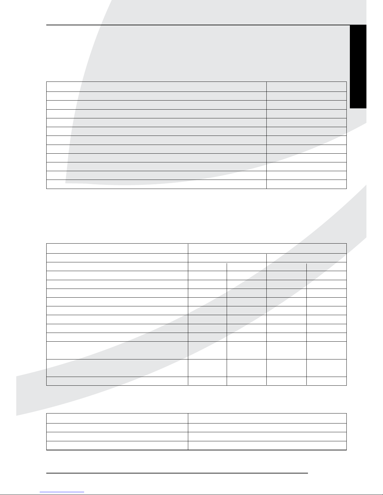
Tabel 2: Meegeleverde onderdelen
Aantal
Onderdeel Global 60i CF
Houtset of kiezelset 1x
Boekje met handleidingen 1x
Bundelklem 1x
Keilbouten M8 2x
Zeskant moer M8 2x
Carrosseriering 2x
Inbussleutel 5 mm 1x
Afstandsbediening 1x
9V blokbatterij 1x
Penlite batterij (type AA) 4x
Land mbar
NL / DK / FI / NO / SE / HU / BA / GR 30
FR / BE / IT / PT / ES / GB / IE 37
DE 50
Tabel 4: Voordruk bij gebruik van G31
Bijlage 2 Technische gegevens
In de onderstaande tabellen staan de technische gegevens van Global 60i CF vermeld.
Tabel 3: Technische gegevens
Type B
11AS
Gassoort G20 G25,3 G31
Branderdruk mbar 15,2 18,8 28
Nom. Belasting (Hs) kW 6,7 6,4 6,6
Nom. Belasting (Hi) kW 6,0 5,8 6,0
Nom. Vermogen kW 4,7 4,4 4,7
Verbruik L/h 637 682 242
Branderspuitstuk mm 7 x Ø 0,81 7 x Ø 0,81 7 x Ø 0,55
Verbruik kleinstand L/h 294 310 159
Kleinstelspuitstuk mm Ø 1,45 Ø 1,45 Ø 1,1
Rendementklasse 2 2 2
Maat restrictieopening bij 2m* tot 4m mm Ø81 Ø81 GEEN
schoorsteenlengte
Maat restrictieopening bij 4m t/m 12m mm Ø50 Ø50 Ø56
schoorsteenlengte
Geschikt voor Class 1 chimney NEE NEE NEE
* = minimale lengte
Page 18

16
Page 19

Nederlands
17
GEBRUIKERSHANDLEIDING
Inhoudsopgave
Woord vooraf ..............................................................................18
1. Inleiding ................................................................................ 18
2. Veiligheid ..............................................................................18
2.1 Algemeen ................................................................................18
2.2 Voorzorgsmaatregelen / veiligheidsinstructies ...............18
3. Ingebruikname ..................................................................18
3.1 Eerste keer .............................................................................18
3.2 Bescherming ...........................................................................19
3.3 Verkleuring van wanden en plafonds ................................19
4. Draadloze afstandsbediening .....................................19
4.1 Vervangen batterijen ontvanger.........................................19
4.2 Afstandsbediening .................................................................20
4.3 Alternatieve bediening .........................................................23
5. Onderhoud .......................................................................... 23
6. Milieu .....................................................................................23
6.1 Algemeen ................................................................................23
6.2 Toestel .....................................................................................23
7. Garantie................................................................................23
Global 60i CF
Page 20

18
GEBRUIKERSHANDLEIDING
Woord vooraf
Als fabrikant van gasverwarmingstoestellen ontwikkelt en
produceert DRU producten volgens de hoogst mogelijke
kwaliteits-, prestatie- en veiligheidseisen.
U kunt hierdoor rekenen op jarenlang gebruiksplezier.
Dit toestel is voorzien van een CE merk. Gastoestellen die
voldoen aan de eisen voor veiligheid, milieu en energiegebruik, de zogenaamde essentiële eisen, uit de Europese Gastoestellenrichtlijn hebben het recht het CE-merk te dragen.
U dient de installatie en het onderhoud van uw toestel te
laten uitvoeren door een vakbekwame installateur op het
gebied van gas sfeerverwarming.
Bij het toestel worden twee handleidingen geleverd:
de installatiehandleiding en de gebruikershandleiding.
Deze zijn in één boekje samengevoegd.
De gebruikershandleiding geeft u de informatie die u nodig
hebt om het toestel goed en veilig te laten functioneren.
U dient deze gebruikershandleiding zorgvuldig te lezen
alvorens het toestel in gebruik te nemen.
U dient het boekje met handleidingen zorgvuldig te
bewaren.
Als gebruiker mag u uitsluitend de werkzaamheden uitvoeren die in de gebruikershandleiding worden genoemd. Voor
de overige werkzaamheden schakelt u een vakbekwame
installateur in.
Neem bij vragen of twijfel altijd contact op met uw installateur.
In de handleidingen worden de volgende markeringen
gebruikt om belangrijke informatie aan te geven:
• Uit te voeren acties.
! Tip Suggesties en adviezen.
! Let op Deze instructies zijn noodzakelijk ter
voorkoming van mogelijke problemen bij
installatie en/of gebruik.
Deze instructies zijn noodzakelijk ter
voorkoming van brand, persoonlijk letsel of
andere ernstige schades.
1. Inleiding
Uw toestel is een open gassfeerverwarmingstoestel, de
Global 40 CF dient te worden ingebouwd, de Global beau
is een Vrijstaand toestel. Een open toestel haalt de verbrandingslucht uit de leefomgeving. Het is daarom van belang
dat de leefruimte goed geventileerd wordt.
Voor de veilige werking van het toestel is een oxypilot
beveiliging aangebracht. Bij onvoldoende aanvoer van verse
lucht grijpt de oxypilot in en wordt het toestel uitgeschakeld.
De bediening van het toestel gebeurt met behulp van een
draadloze afstandsbediening; deze werkt op batterijen.
2. Veiligheid
2.1 Algemeen
- Leest u dit hoofdstuk over veiligheid
zorgvuldig door;
- Houdt u zich aan de maatregelen/
instructies in deze handleiding.
2.2 Voorzorgsmaatregelen / veiligheidsinstructies
Volg de onderstaande maatregelen/voorschriften nauwkeurig op:
• laat de installatie en het onderhoud van het toestel uit-
voeren door een vakbekwame installateur op het gebied
van gas sfeerverwarming;
• breng zelf geen wijzigingen aan het toestel aan;
• laat het onderhoud minimaal 1x per jaar uitvoeren;
• sluit de gaskraan als het toestel met een plof en/of slecht
ontsteekt en waarschuw de installateur;
• sluit de gaskraan bij storingen en/of slecht functioneren
van het toestel en neem contact op met de installateur;
• bij een gebroken of gescheurde ruit het toestel niet ge-
bruiken en de ruit meteen vervangen;
• zorg voor voldoende ventilatie in de ruimte waar het
toestel is geplaatst;
• houd brandbare voorwerpen en/of materialen zoals over-
gordijnen op minimaal 50 cm afstand van het toestel en/of
de afvoerpijpen;
• laat geen kleding, handdoeken e.d. op en/of dichtbij het
toestel drogen ter voorkoming van brand;
• vermijd contact met hete delen van het toestel ter voor-
koming van brandwonden;
• laat kinderen en personen die de consequenties van hun
handelen slecht overzien nooit alleen bij een brandend
toestel;
• leg de afstandsbediening buiten het bereik van kinderen
en personen die de consequenties van hun handelen
slecht overzien.
3. Ingebruikname
3.1 Eerste keer
Bij toepassing van een boezem moet deze – voordat u het
toestel in gebruik neemt – droog zijn ter voorkoming van
krimpscheuren.
!Let op Als de boezem van steenachtige mate-
rialen is gemaakt of is afgewerkt met
stucwerk dient deze minimaal 6 weken te
drogen vóór ingebruikname.
Tijdens de eerste keer stoken kan er een onaangename
geur ontstaan door het uitdampen van vluchtige componenten uit verf, materialen e.d.. Dit kan meerdere uren in
beslag nemen.
!Let op - Huisdieren en vooral vogels kunnen ge-
voelig zijn voor de vrijkomende dampen;
Let op
Let op
Page 21

Nederlands
19
GEBRUIKERSHANDLEIDING
- Het vlambeeld wordt in het begin beïnvloed door het uitdampen van vluchtige
componenten.
!Tip - Zet het toestel in de hoogste stand om
het uitdampen te versnellen;
- Ventileer de ruimte goed;
- Verwijder huisdieren uit de ruimte.
3.2 Bescherming
Om onveilige situaties te voorkomen, dient u de onderstaande maatregelen/instructies nauwkeurig op te volgen.
- Zorg voor voldoende ventilatie in de
ruimte waar het toestel is geplaatst;
- Houd brandbare voorwerpen en/of materialen zoals overgordijnen op minimaal
50 cm afstand van het toestel en/of de
afvoerpijpen;
- Laat geen kleding, handdoeken e.d. op en/
of dichtbij het toestel drogen ter voorkoming van brand;
- Vermijd contact met hete delen van het
toestel ter voorkoming van brandwonden;
- Laat kinderen en personen die de consequenties van hun handelen slecht overzien nooit alleen bij een brandend toestel;
- Leg de afstandsbediening buiten het
bereik van kinderen en personen die de
consequenties van hun handelen slecht
overzien.
3.3 Verkleuring van wanden en plafonds
Bruinverkeuring is een vervelend en moeilijk op te lossen
probleem. Bruinverkleuring kan worden veroorzaakt door
stofverbranding als gevolg van te weinig ventilatie, roken,
branden van kaarsen, olielampjes e.d.. Rook van sigaretten
en sigaren bevat teerstoffen die op koudere muren neerslaan.
Deze problemen kunnen (deels) voorkomen worden door
goede ventilatie van de ruimte waar het toestel staat.
4. Draadloze afstandsbediening
Het toestel wordt bediend met een afstandsbediening.
Zowel het ontsteken, het regelen van de vlamhoogte als het
uitschakelen gebeurt met behulp van de afstandsbediening,
die een ontvanger aanstuurt.
De ontvanger en de afstandsbediening worden gevoed met
batterijen. Voor de ontvanger zijn 4 penlite (type AA) batterijen nodig; voor de afstandsbediening een 9V-blokbatterij.
De levensduur van de batterijen is bij normaal gebruik
ongeveer een jaar.
Als optie kan een adapter worden gebruikt. Informeer hiernaar bij uw installateur. U hebt dan een 230 V aansluiting
nodig in de omgeving van het toestel.
4.1 Vervangen batterijen ontvanger
Als de batterijen van de ontvanger bijna leeg zijn hoort u
3 korte piepjes mits het motortje voor de regeling van de
hoofdbrander draait (zie paragraaf 4.2.1.1).
• Draai de inbusbout aan de linker zijkant van de deur los
(zie Afb. 1);
Let op
Global 60i CF
B
K
38C-1939 /0
2a
2b
1
38C-1937 /0
Page 22

20
GEBRUIKERSHANDLEIDING
!Let op Zorg ervoor dat bij het los- of vastdraaien van
de inbusbout de inbussleutel niet tegen de deur
aan komt om beschadiging te voorkomen;
• Open de deur;
• Til de batterijklep (B) omhoog en trek deze voorzichtig
onder de verbrandingskamer weg (zie Afb. 2a);
!Let op Vermijd contact tussen batterijklep en kader
om beschadiging te voorkomen;
• De ontvanger is nu zichtbaar en ligt in de houder (zie Afb.
2b pijl 1);
• Til de ontvanger onder de verbrandingskamer weg (zie
Afb. 2c);
• Schuif de deksel eraf;
• Plaats of verwijder de 4 penlite (type AA) batterijen.
!Let op - Vermijd kortsluiting tussen de batterijen en
metalen voorwerpen/delen;
- Let op de “+” en “-” polen van de batterijen en
de houder;
- Gebruik alkaline batterijen;
• Schuif de deksel terug;
• Plaats de ontvanger terug in de houder (1) zoals aangege-
ven in Afb. 2b.
• Plaats de batterijklep (B) terug onder de verbrandings-
kamer. Houd deze vlak en schuif de klep langs de kap (K)
naar beneden totdat de klep gelijk loopt met de kap (zie
Afb. 2a);
!Let op - Zorg ervoor dat er geen kabels onder de
ontvanger liggen;
- Zorg ervoor dat er geen kabels op de batterijklep liggen;
- Batterijen vallen onder “klein chemisch afval”
en mogen dus niet bij het huisvuil.
4.2 Afstandsbediening
De standaard functies van het toestel zoals het ontsteken,
regelen van de vlamhoogte, stand-by (waakvlam) stand en
uitschakelen worden uitgevoerd in de MAN stand, de handmatige regeling van de afstandsbediening (zie Afb. 3).
Daarnaast kan met behulp van de afstandsbediening een
aantal extra functies ingesteld worden:
- temperatuurweergave in graden Celsius of Fahrenheit;
- tijd;
- thermostaat functie;
- timer voor thermostaat functie.
Hoewel de kans klein is, is niet uit te
sluiten dat het ontstekingsproces van uw
toestel onbedoeld wordt gestart door
andere draadloze afstandsbedieningen.
Hierbij wordt gedacht aan de afstandsbediening van een gashaard van buren,
maar ook aan autosleutels en garagedeur
openers.
Het gevolg is dat uw toestel gaat branden
zonder dat u het wilt.
U kunt het onbedoeld ontsteken van uw toestel eventueel
verhelpen/voorkomen door de gaskraan bij uw toestel te
sluiten. Dit is de veiligste maatregel als het toestel gedurende een lange periode niet wordt gebruikt.
Neem - ook als het toestel niet in gebruik is - de genoemde
voorzorgsmaatregelen/ veiligheidsinstructies in acht.
4.2.1 MAN stand
Door kort op de knop SET te drukken doorloopt u achtereenvolgens de volgende functies:
MAN Y TEMP TEMP (P*)TIMER MAN
waarbij afhankelijk van de instelling van de timer:
(P*) wordt weergegeven als P1 Y, P1 , P2 Y, P2
!Tip U kunt ook terugkeren naar de MAN
stand door op de knop
(grote vlam) of
(kleine vlam) te drukken.
Let op
2c
3
Page 23

Nederlands
21
GEBRUIKERSHANDLEIDING
!Let op - Bij het indrukken van de knoppen (be-
halve de knop SET) verschijnt het transmissiesymbool ( ) om aan te geven
dat er transmissie plaatsvindt tussen de
afstandsbediening en de ontvanger;
- De ontvanger bevestigt de transmissie
met een geluidssignaal;
- Het toestel gaat automatisch naar de
stand-by stand als er gedurende 6 uur
geen transmissie plaatsvindt.
• Zet de afstandsbediening op de MAN stand.
4.2.1.1 Ontsteken
- Wacht altijd 5 min. na het doven van de
waakvlam voordat u het toestel opnieuw
ontsteekt;
- Bij gebruik van propaan is extra oplettendheid geboden. De waakvlam kan doven door lucht in de leiding b.v. als gevolg
van het vervangen van een propaanes:
Houdt u zich strikt aan de wachttijd van
5 min. voordat u het ontstekingsproces
opnieuw start;
- Sluit de gaskraan bij storingen en/of slecht
functioneren en waarschuw de installateur.
!Tip Gebruik voor toestellen op propaan een
systeem met twee essen voorzien van
een automatische omschakeling naar de
reservees als losse gasessen worden
toegepast.
Het ontsteken van het toestel gaat als volgt:
• Druk de knoppen OFF en
(grote vlam) op de afstands-
bediening gelijktijdig in.
• Laat de knoppen los als een kort geluidssignaal aangeeft
dat het ontstekingsproces is gestart.
Achtereenvolgens:
- geven doorlopende signalen aan dat het ontstekingsproces
in werking is;
- geeft een kort geluidssignaal aan dat het ontstekingspro-
ces is voltooid;
- schakelt het toestel automatisch door naar de hoogste
stand van de hoofdbrander; deze gaat binnen enkele
seconden branden.
- Als de waakvlam na 3 ontsteekpogingen
niet brandt, moet u de gaskraan dichtdraaien en de installateur waarschuwen;
- Tijdens het ontsteken van de waakvlam
hoort u geluidssignalen. Na het laatste
korte geluidssignaal dient de hoofdbrander binnen circa 10 seconden grotendeels
ontstoken te zijn. Als dit niet gebeurt,
draait u de gaskraan dicht en waarschuwt
u de installateur;
Let op
- Als het toestel met een plof ontsteekt,
sluit u de gaskraan en waarschuwt u de
installateur.
!Tip Er gaat een motortje lopen als de hoofd-
brander in bedrijf komt; dit is hoorbaar.
4.2.1.2 Vlamhoogte / Stand-by
De vlamhoogte kan traploos geregeld worden met behulp
van de knoppen
(kleine vlam) en (grote vlam). Door de
vlamhoogte steeds verder te verlagen kan het toestel in de
stand-by stand gezet worden; dat wil zeggen dat alleen de
waakvlam nog brandt.
• Druk op de knop (kleine vlam) om de vlamhoogte te
verlagen en/of het toestel in de stand-by stand te zetten.
• Druk op de knop
(grote vlam) om de vlamhoogte te
verhogen en/of de hoofdbrander in te schakelen vanuit de
stand-by (waakvlam) stand.
- Bij het ingedrukt houden van de knop
(grote vlam) op de afstandbediening moet
de hoofdbrander binnen circa 10 seconden grotendeels ontstoken zijn. Als dit
niet gebeurt, draait u de gaskraan dicht en
waarschuwt u de installateur;
- Als het toestel met een plof ontsteekt
sluit u de gaskraan en waarschuwt u de
installateur.
4.2.1.3 Uitschakelen
Het toestel wordt uitgeschakeld door op de knop OFF te
drukken. Ook de waakvlam gaat dan uit.
4.2.2 Temperatuurweergave
De kamertemperatuur kan op het display in graden Celsius
(ºC) met een 24-uursklok of in graden Fahrenheit (ºF) met
een 12-uursklok weergegeven worden.
• Druk de knoppen OFF en
(kleine vlam) gelijktijdig in
totdat op het display de gewenste weergave verschijnt.
4.2.3 Tijd
Op het display kan de tijd weergegeven worden.
Na het plaatsen van de batterij of het gelijktijdig indrukken
van de knoppen
(grote vlam) en (kleine vlam) knippert
de tijdsaanduiding op het display en kan de tijd ingesteld
worden.
• Druk gelijktijdig op de knoppen
en totdat de tijdsaan-
duiding op het display knippert.
• Druk op de knop
(grote vlam) om de uren in te stellen.
• Druk op de knop (kleine vlam) om de minuten in te
stellen.
• Druk op OFF om terug te keren naar de MAN stand of
wacht tot het systeem automatisch terugkeert naar de
MAN stand.
Let op
Let op
Global 60i CF
Page 24

22
GEBRUIKERSHANDLEIDING
4.2.4 Thermostaat functie
U kunt met behulp van de thermostaat functie twee temperaturen instellen die thermostatisch geregeld worden. Deze
temperaturen worden aangeduid als dagtemperatuur en
nachttemperatuur.
Het Y TEMP en TEMP symbool op het display staan resp.
voor dag- en nachttemperatuur.
De kamertemperatuur wordt vergeleken met de ingestelde
dag-/nachttemperatuur en de vlamhoogte wordt daarna
automatisch geregeld om de ingestelde temperatuur te
bereiken.
Om de dag-/nachttemperatuur functie te kunnen gebruiken
moet het toestel in de stand-by stand staan.
!Let op - Leg de afstandsbediening steeds op
dezelfde plek, zodat de thermostaat de
omgevingstemperatuur ’voelt’;
- Zorg dat deze plek vrij is van invloeden
als tocht, warmte van radiatoren en
rechtstreeks zonlicht.
Voorbeeld
M.b.v. de Y TEMP functie kunt u overdag de temperatuur
op 20 ºC houden, terwijl u m.b.v. de TEMP functie ’s
nachts een temperatuur van 15 ºC handhaaft.
4.2.4.1 Instellen dag-/nachttemperatuur
Met behulp van de knop SET doorloopt u achtereenvolgens
de volgende functies:
MAN Y TEMP TEMP (P*) TIMER MAN
• Druk kort op de knop SET om in de Y TEMP of de
TEMP stand te komen.
• Druk de knop SET in totdat de temperatuur op het dis-
play knippert.
• Stel de gewenste temperatuur in met de knoppen
(grote vlam) en (kleine vlam).
!Let op - De minimaal in te stellen temperatuur
bedraagt 5 ºC / 40 ºF;
- De regeling van de nachttemperatuur
wordt uitgeschakeld door de temperatuur te verlagen totdat twee streepjes
(“--”) op het display verschijnen.
• Druk op de knop OFF of wacht totdat op het display de
stand Y TEMP of TEMP verschijnt.
4.2.4.2 Activeren thermostaat functie
Voor het activeren van de thermostaat functie volgt u onderstaande stappen:
• Zet het toestel in de stand-by (waakvlam) stand m.b.v. de
knop
(kleine vlam).
• Stel de dag-/nachttemperatuur in.
• Kies de Y TEMP dan wel de TEMP functie met behulp
van de knop SET.
4.2.5 Timer voor thermostaat functie
Met behulp van de timer kunnen per etmaal twee tijden
ingesteld worden om de dagtemperatuur en twee tijden om
de nachttemperatuur in te schakelen.
Om de nachttemperatuur te regelen moet deze minimaal
op 5 ºC / 40 ºF ingesteld worden.
Als de nachttemperatuur op de “--” stand ingesteld wordt,
blijft het toestel in de stand-by stand staan. Het toestel
schakelt pas weer in bij de volgende inschakeltijd van de
dagtemperatuur.
Het toestel moet in de stand-by stand staan om d.m.v. de
timer geregeld te worden.
Voorbeeld schakeltijden
U hebt een dagtemperatuur resp. nachttemperatuur ingesteld van b.v. 20 ºC en 15 ºC.
P1 Y TIMER = 7 uur; de temperatuur gaat om 7 uur naar
20 ºC.
P1 TIMER = 9 uur; de temperatuur gaat om 9 uur naar
15 ºC.
P2 Y TIMER = 17 uur; de temperatuur gaat om 17 uur
weer naar 20 ºC.
P2 TIMER = 22 uur; de temperatuur gaat om 22 uur
terug naar 15 ºC.
4.2.5.1 Instellen tijden t.b.v. timer
Volg onderstaande stappen om de timer in te stellen:
• Stel de dag- en nachttemperuur in zoals hierboven beschreven bij paragraaf 4.2.4.1.
• Druk kort op de knop SET om in de (P*) TIMER stand te
komen.
• Druk de knop SET in totdat P1 YTIMER verschijnt en de
tijd knippert.
• Stel de eerste inschakeltijd van de dagtemperatuur in met
de knoppen
(grote vlam) en (kleine vlam).
• Druk kort op de knop SET om de volgende tijd van de
cyclus, P1 TIMER, in te stellen.
• Stel achtereenvolgens de tijden P2 Y TIMER en
P2 TIMER in.
• Druk op de knop OFF of wacht totdat op het display de
stand (P*) TIMER verschijnt.
4.2.5.2 Activeren timer functie
Volg de onderstaande stappen voor het activeren van de
timerregeling:
• Zet het toestel in de stand-by (waakvlam) stand m.b.v.
knop
(kleine vlam).
• Stel de dag-/nachttemperatuur in als dit nog niet is
gebeurd; zie hiervoor paragraaf 4.2.4.1.
• Stel de timer tijden P1 Y TIMER, P1 TIMER,
P2 Y TIMER en P2 TIMER in.
• Kies de (P*) TIMER functie met behulp van de knop SET.
Page 25

Nederlands
23
GEBRUIKERSHANDLEIDING
4.2.6 Vervangen batterij afstandsbediening
Als de batterij bijna leeg is verschijnt “BATT” op het display.
U kunt de batterij als volgt vervangen:
• Verwijder de deksel aan de achterzijde van de afstandsbediening.
• Koppel de 9V-blokbatterij los van / sluit de 9V blokbatterij
aan op de connector.
!Let op - Let op de “+” en “-” polen van de batterij
en de connector;
- Gebruik alkaline batterijen;
- Batterijen vallen onder “klein chemisch
afval” en mogen dus niet bij het huisvuil.
• Plaats de batterij in de houder.
• Sluit de deksel.
4.3 Alternatieve bediening
Indien er gebruik wordt gemaakt van een Domotica
systeem voor uw haard, speelt de instelling van de meegeleverde afstandsbediening een rol. Zie hiervoor de installatiehandleiding hoofdstuk 7.4.
5. Onderhoud
Het toestel dient minimaal één keer per jaar op zijn goede
en veilige werking gecontroleerd te worden.
- Laat het onderhoud van uw toestel
uitsluitend uitvoeren door een vakbekwame installateur op het gebied van gas
sfeerverwarming;
- Laat een gescheurde of gebroken ruit
meteen vervangen;
- Breng zelf geen wijzigingen aan het toe-
stel aan.
!Let op Als gebruiker mag u het toestel alleen aan
de buitenkant schoonmaken:
- Gebruik geen bijtende of schurende
schoonmaakmiddelen;
- Lakbeschadigingen, die het gevolg zijn van
voorwerpen die op/tegen de mantel van
het toestel zijn gevallen/geplaatst, vallen
niet onder de garantie.
6. Milieu
6.1 Algemeen
Verpakkingsmaterialen moeten afgevoerd worden via de
reguliere weg.
Batterijen vallen onder klein chemisch afval en horen in de
daarvoor bestemde containers te worden geplaatst.
6.2 Toestel
Aan het einde van de levensduur moet u het toestel op
een verantwoorde wijze laten verwerken, zodat het toestel of onderdelen daarvan kunnen worden hergebruikt.
Let op
Let op
Voer de volgende handelingen uit voordat
u tot verwijderen overgaat:
- Sluit eerst de gaskraan;
- Draai vervolgens de koppeling tussen
toestel en gaskraan los.
• Verwijder het toestel
• Zet het toestel niet bij het ongesorteerde afval, maar
lever het in bij een erkend inzamelpunt.
• Neem contact op met uw gemeente voor informatie over
beschikbare inleverings- en inzamelsystemen.
7. Garantie
De garantie op uw DRU toestel wordt verleend via uw
leverancier. In geval van klachten dient u altijd met hem
contact op te nemen. Uw leverancier zal DRU inschakelen
als hij dit noodzakelijk acht. De fabrieksgarantie bedraagt 2
jaar na datum van aankoop.
Global 60i CF
Page 26

24
Page 27

Global 60i CF
English
25
INSTALLATION MANUAL
Contents
Preface .........................................................................................26
1. Introduction ........................................................................26
2. CE declaration ...................................................................26
3. SAFETY ................................................................................ 26
3.1 General ....................................................................................26
3.2 Regulations .............................................................................26
3.3 Precautions / safety instructions during installation ......27
3.4 Oxypilot safety ......................................................................27
4. Instructions ......................................................................... 27
5. Removing the packaging...............................................27
6. Installation ........................................................................... 27
6.1 Regulations .............................................................................27
6.2 Type of gas ..............................................................................27
6.2.1 Reconstruction to different type of gas ..........................27
6.3 Gas connection .....................................................................28
6.4 Placing the appliance ............................................................28
6.5 Flue gas discharge system ...................................................29
6.6 Placing the chimney breast .................................................30
6.7 Placing the wood or pebble set .........................................30
6.8 Door ........................................................................................30
7. Control/operation ............................................................31
7.1 Connecting the receiver ......................................................31
7.2 Setting the communication code .......................................32
7.3 Replacing the receiver .........................................................32
7.4 Alternative operation ...........................................................32
8. Final check ...........................................................................33
8.1 Gastightness ...........................................................................33
8.2 Gas pressure / line-pressure...............................................33
8.3 Ignition pilot burner and main burner .............................33
8.4 Flame image ............................................................................34
9. Maintenance ....................................................................... 34
9.1 Parts .........................................................................................34
10. Delivery ................................................................................34
11. Malfunctions .......................................................................34
Appendix 1 Parts included with the delivery .............38
Appendix 2 Technical data ...................................................38
Appendix 3 Figures .................................................................46
Page 28

26
INSTALLATION MANUAL
Preface
DRU, a manufacturer of gas-red heating appliances,
develops and produces products that comply with the
highest quality, performance and safety requirements.
This guarantees that the user will be able to enjoy using his
product for many years to come.
This appliance has a CE marking, which means that it
complies with the essential requirements of the European
gas appliance directive.
Two manuals are supplied with the appliance: the installation manual and the user manual. These have been included
in one booklet.
As an installer, you must be competent in the eld of
atmospheric gas-red heating.
The installation manual will give you the information you
need to install the appliance in such a way that it will
operate properly and safely.
This manual discusses the installation of the appliance and
the regulations that apply to the installation. In addition, you
will nd technical data for the appliance and information on
maintenance, any malfunctions that might occur and their
possible causes.
The gures are included at the back of this booklet
(Appendix 3).
Please carefully read and use this installation manual.
The following symbols are used in the manual to indicate
important information:
• Work to be performed.
! Tip Suggestions and recommendations.
! Caution You will need these instructions to prevent
problems that might occur during installation and/or use.
You need these instructions to prevent re,
personal injury or other serious damages.
After delivery you should give this booklet containing
the manuals to the user.
1. Introduction
The Global 60i CF is an open-ued atmospheric gas
red heating appliance. An open-ued appliance draws its
combustion air from the living area. The living area must be
ventilated sufciently, in order to provide the appliance with
combustion air. To guarantee a safe operation of the appliance, an oxypilot safeguard has been installed. If the supply
of air is insufcient, the oxypilot will intervene and switch
off the appliance. Global 60i CF was specially designed for
construction in an existing hearth/replace, whereby the
entire length of the existing chimney must always be provided with a exible stainless steel pipe. The ue spigot has
a 20° backward inclination, allowing easy connection. It is
also possible to build the appliance in a newly to be placed
chimney breast, provided the ue spigot and required ventilation are taken into account. In most cases, the chimney
breast must be ventilated in order to achieve a good heat
discharge (see chapter 6.6). DRU is able to supply various
ventilation elements. The appliances are supplied with a
wireless remote control that works on batteries.
2. CE declaration
We hereby declare that the design and construction of
DRU’s atmospheric gas-red heating appliance comply with
the essential requirements of the Gas Appliance Directive.
Product: atmospheric gas-red heating appliance
Type: Global 60i CF
Applicable EEC directives:
2009/142/EC
Applied harmonized standards:
NEN-EN-613
NEN-EN-613/A1
Internal measures by the company guarantee that appliances produced in series comply with the essential requirements of the prevailing EEC directives and the standards
derived from them.
This declaration will lose its validity if adjustments are made
to the appliance, without prior written permission by DRU.
You will be able to download a copy of the test certicate
via www.druservice.com.
M.J.M. Gelten
General manager
DRU verwarming B.V.
Postbus 1021, 6920 BA Duiven
Ratio 8, 6921 RW Duiven
www.dru.nl
3. Safety
3.1 General
- Carefully read this chapter on safety,
before you start performing installation or maintenance work;
- Please observe the general regulations and the precautions/safety
instructions in this manual.
3.2 Regulations
Please install the appliance in accordance with the
applicable national, local and constructional (installation)
regulations.
3.3 Precautions / safety instructions during
installation
Strictly observe the following precautions/safety
regulations:
• you should only install and maintain the appliance if you
are a competent installer in the field of atmospheric
gas-fired heating;
• do not make any changes to the appliance;
Caution
Caution
Page 29

English
27
Global 60i CF
INSTALLATION MANUAL
• provide sufficient ventilation holes in the installation area;
in accordance with local regulations;
• use non combustible and heat-resistant materials for the
chimney breast, including the top of the chimney breast,
the material in the chimney breast, the floor in the chimney breast and the back wall against which the appliance
will be placed;
• take sufficient measures to prevent temperatures of a wall
behind the chimney breast becoming too high, including
the materials and/or objects behind the wall;
• comply with the minimum required internal measurements of the chimney breast;
• ventilate the chimney breast by means of the ventilation
holes, which will form a combined passage of at least
200 cm2 (see chapter 6.6);
• use a suitable flue gas discharge system that is provided
with the CE mark;
• maintain a minimum distance of 10 mm between the
appliance and the back wall;
• Maintain a minimum distance of 10 mm between the back
wall (non-combustible) and the built-in appliance (Global
60i CF)
• do not cover the appliance and/or do not wrap it in an
insulation blanket or any other material;
• make sure that combustible objects and/or materials have
a distance from the appliance of at least 500 mm;
• take the distance (see fig. 2) from the appliance to a com-
bustible floor in front of the appliance into account;
• only use the accompanying wood/pebble set and place it
exactly as described;
• make sure the pilot burner and the space around it is kept
free;
• make sure there is no dirt in gas pipes and connections;
• mount a gas tap directly next to the appliance;
• check the connections for gastightness before using the
appliance;
• replace a torn or broken glass pane;
• In case of a broken or torn glass pane, do not use the ap-
pliance and close the gas tap.
• do not ignite the appliance until it is fully installed.
3.4 Oxypilot safety
The appliance is provided with an oxypilot safety, which
will be activated if insufficient combustion air (oxygen) is
supplied.
If the oxypilot safety senses insufficient oxygen, the pilot
burner is switched off and the gas supply to the burner is
closed.
If the supply of combustion air is sufficient again, the
appliance can be restarted.
! Caution In case of a house with a mechanic exhaust
system and/or an open kitchen with
cooker hood, a permanent ventilation
opening is required in the area surrounding
the appliance; for this application, please
refer to the gas installation provisions and
local regulations.
4. Instructions
Observe the following items during installation in order to
guarantee a proper and safe operation of the appliance:
• use the plaster strip in case of a tight construction and
properly nish the edges;
• do not apply plaster on or over the anges;
• avoid damages when removing/placing the glass pane;
• clean the glass pane before you use the appliance, in order
to prevent dirt from burning in the glass.
5. Removing the packaging
Note the following items when removing the packaging:
• Remove all packaging materials;
• Remove all supplied components in, on and/or at the
appliance;
• Check the appliance and accessories for damages during
transport.
• If necessary, contact DRU Service.
Keep all plastic bags away from children.
In appendix 1/ table 2 you can see which parts you should
have after removing the packaging.
• Contact DRU Service if you do not have all the parts after
you nished removing the packaging.
• Dispose packaging in accordance with local regulations.
6. Installation
Read this manual carefully to ensure a proper and safe
operation of the appliance.
!Caution Install the appliance in the order described
in this chapter.
6.1 Regulations
• Observe the applicable (installation) regulations.
• Observe the regulations/instructions in this manual.
6.2 Type of gas
The heat shield of the battery cover indicates for which
type of gas, gas pressure and for which country this appliance is intended. The battery cover can be found under
the combustion chamber (see User Manual g. 2a). The appliance may not be used if the battery cover is not properly
mounted.
Check whether the appliance is suitable for
the type of gas and the gas pressure used at
the location.
6.2.1 Reconstruction to different type of gas
If you want to convert this appliance into a different type of
gas, please contact DRU's service department and ask what
is possible. Reconstructions should only be performed by
authorized gas installers.
Caution
Caution
Page 30

28
INSTALLATION MANUAL
6.3 Gas connection
Place a gas tap in the gas connection, close to the appliance.
- Make sure there is no dirt in gas pipes and
connections;
- Prevent twisting the gas tap when connecting the gas pipe.
The following requirements apply to the gas connection:
- use a gas pipe with the correct dimensions, so that no
pressure loss can occur;
- the gas tap should have the CE marking;
- you should always be able to reach the gas tap.
6.4 Placing the appliance
This appliance is only suitable for installation with a exible
stainless steel pipe for the discharge of ue gases.
- Make sure that combustible objects and/or
materials have a distance from the
appliance of at least 500 mm;
- Always place the appliance against a wall of
non combustible and heat-resistant
material;
- Maintain a minimum distance of 10 mm
between the appliance and the back wall;
- Take sufcient measures to prevent tempe-
ratures of a wall behind the chimney breast
becoming too high, including the materials
and/or objects behind the wall;
- Place the appliance on supports made of
non combustible and heat-resistant
material;
- Do not cover the appliance and/or do
not wrap it in an insulation blanket or any
other material;
- Do not make any changes to the appliance.
!Caution - Take the minimum construction depth of
the appliance into account;
Global 60i CF 380 mm (see g. 2);
Place the appliance as follows:
• Determine the location of the appliance; see g. 1 for the
dimensions of the appliance.
• Determine the construction height of the appliance.
• Provide a gas connection at the location. For details, see
section 6.3.
• Make a passage for the ue gas discharge system with the
following diameters. For details, see section 6.5.
- Ø110 mm for a roof terminal through non combustible
material;
- Ø 200 mm for a roof terminal through combustible material.
• Level the appliance on its destined location.
• Connect the gas pipe to the appliance, as described below.
The gas control is located below the burner. In order to
connect the gas pipe, you must remove the burner mounting
plate. In order to fasten the appliance to the back wall, the
combustion chamber must be removed from the convection
box.
Follow the procedure described below:
• Remove the door (zie paragraag 6.8);
• Store the door on a safe place;
• Screw the screws (2x) on both sides out of the frame with
the supplied Allen wrench and pull the frame out of the
convection box (see Figure 3a.)
• Remove the two self-tapping screws from the cover under
the combustion chamber (see g. 3b);
• Remove the hood with battery cover under the combustion chamber;
• Remove the vermiculite tray (see g.4a);
• Unscrew the 4 self-tapping screws of the burner plate and
remove the burner plate plus accessories (see g. 4b);
• Unscrew the 8 self-tapping screws of the seal plate and
remove the seal plate from the combustion chamber (see
g. 4c);
• Unscrew the 4 self-tapping screws of the ue spigot and
remove the ue spigot from the combustion chamber (see
g. 4d);
• Unscrew the Allen screws (2x) at both sides of the combustion chamber using the supplied Allen key (see g. 4e);
!Tip Make sure that the 4 holes at the top of
the combustion chamber where the ue
spigot has to be attached are in line with
the 4 holes of the convection box.
• Grab the combustion chamber at both sides and remove it;
!Tip If the dimensions of the construction
opening allow this, the supplied adjustable
feet can be mounted to the bottom of the
convection box, allowing easy levelling.
• Make sure the oor on which the convection box will be
placed is even and level, if no adjustable feet are used;
• The gas supply pipe should reach into the convection box,
via the grommet (see g. 4f);
!Tip Allow the gas supply pipe to protrude into
the convection box by approx. 85mm, so it
can be easily reached when using tools;
!Caution Keep the gas supply pipe as low as possible
in the convection box, so that the combustion chamber does not press down on the
pipe when it is installed;
• Connect the convection box of the built-in appliance to the
wall using the supplied key bolts and body rings
(see 1 g. 4f);
• Place the combustion chamber back in the convection box
and fasten it at both sides with the Allen screws
(see g. 4e);
• Determine the required restrictor opening and connect the
ue spigot to the exible stainless steel pipe (see chapter
6.5);
Caution
Caution
Page 31

English
29
INSTALLATION MANUAL
Global 60i CF
• Place back the ue spigot in the combustion chamber and
tighten it with the 4 self-tapping screws (see g. 4d);
• Place back the seal plate, using the 8 self-tapping screws
(see g. 4c);
• If necessary, blow clean the gas pipe;
• Connect the exible gas pipe to the gas supply pipe;
• Bleed the gas pipe;
• Check the line-pressure as described in section 8.2 of the
installation manual;
• Check the connections for gas tightness as described in
section 8.1 of the installation manual;
• Place back the burner mounting plate plus accessories and
x it with the self-tapping screws;
- Avoid kinks and tensions in de exible gas
pipe;
Place the wood set; see section 7.1
• Set the communication code between the remote control
and the receiver; see section 7.2;
- Do not ignite the appliance until it is fully
installed;
!Caution - Place the cables under the clamp (2) so
they cannot make contact with hot parts
when placing the receiver;
- Place the receiver in the holder (1);
- Allow the ignition cable (A) to lie free, as
shown;
• Return the hood with battery cover under the combustion
chamber;
• Fix the cover with the self tapping screws (see g. 3b);
!Caution Check whether it is possible to replace the
batteries (see section 7.1.1);
• Place the vermiculite tray back in the combustion chamber;
!Caution Positioneer de bak om de brander op
de juiste plaats door middel van de stop
edges;
• Place the frame back on the combustion chamber
(see g. 3a);
• Place the wood set or pebble set; see section 6.7;
• Place the door; see section 6.8.
6.5 Flue gas discharge system
This appliance can only be installed with a exible stainless
steel pipe for the discharge of ue gases.
The dimensions of the restrictor slide to be placed in the
ue spigot depends on the length of the chimney and the
type of gas used (see table 3 and g. 4h);
6.5.1 General
The appliance is of the B
11AS
type.
The passage to the outside is made with a roof terminal
(see section 6.5.2).
Use a suitable Ø100 mm diameter ue
gas discharge system provided with the
CE mark.
The ue gas discharge system is constructed from (the ue
spigot of) the appliance.
6.5.2 Connecting the ue gas discharge system
A Ø100 discharge pipe of at least 2 metres should be connected to the appliance. It is not allowed to apply horizontal pieces in the ue gas discharge system.
The roof terminal can end in a sloping and a at roof.
A draft increasing hood is recommended here
- Maintain a distance of at least 50 mm
between the outside of the ue gas
discharge system and the walls and/or
the ceiling. If the system is built in (for
instance) a cove, it should be made with
non combustible material all around it;
- Use heat-resistant insulation material
when passing through combustible
material.
!Caution Some heat-resistant insulation materials
contain volatile components that will
spread an unpleasant smell for a prolonged
time; these are not suitable.
Place the ue gas discharge system as follows:
• Build the system up from (the ue spigot of) the
appliance.
• Unscrew the 8 self-tapping screws of the seal plate and
remove the seal plate from the combustion chamber (see
g. 4c);
• Unscrew the 4 self-tapping screws of the ue spigot and
remove the ue spigot from the combustion chamber
(see g. 4d);
• If the retrictor slide (R) is necessary, adjust it to the right
size by breaking off the rings (see table 3 and g. 4h) and
place it in the ue spigot, making sure it properly ts in
the bottom;
• Connect the exible stainless steel exhaust pipe;
!Tip It is possible to remove the ue spigot
from the combustion chamber and connect the stainless steel pipe from within
the appliance;
• Connect the exhaust hood to the exible stainless steel
exhaust pipe.
!Caution - Make sure that the universal tile ts well
with the surrounding tiles;
Caution
Caution
Caution
Caution
Page 32

30
INSTALLATION MANUAL
- Make sure that the adhesive plate ts well
onto the at roof.
6.6 Placing the chimney breast (if applicable)
This section describes how the Global 60i CF is built into a
chimney breast. In order to provide proper heat discharge,
there should be sufcient space around the appliance. The
chimney breast should be ventilated sufciently by means
of ventilation holes. No ventilation is required in case of an
existing chimney with a masoned replace that is sufciently able to absorb the heat.
- Use non combustible and heat-resistant
materials for the chimney breast, including the top of the chimney breast, the
material in the chimney breast and the
back wall of the chimney breast;
- Make sure that the appliance is not carrying the weight of the chimney breast
when using stone-like materials;
- The ventilation holes – which should be
mounted as high as possible – should have
a combined passage of at least 200 cm2.
!Caution - If possible, you should place decorative
strips, frames, etc., after any required
structural work has been completed;
Avoid the use of painter's tape. If this
is not possible: please use good quality
painter's tape and remove it immediately
after plastering or painting work has been
completed.
- Take the minimum internal width of the
chimney breast into account: 800 mm
(see g. 2);
- When placing the chimney breast, you
should take the location of the ventilation
holes (V) into account (see g. 2).
!Tip You should preferably apply the ventilation
holes on both sides, above and below the
chimney breast. You can use DRU ventilation elements.
• Check whether the ue gas discharge system is placed
correctly.
• If applicable, check the xture of the clip binding with self-
tapping screws on places that cannot be reached later on.
• Do not apply plaster on or over the anges (see g. 2),
because the heat of the appliance could cause cracks.
• The chimney breast is placed behind the edge of the
convection box;
• When using stone-like materials and/or plaster nishing,
the chimney breast should dry for at least 6 weeks before
it is taken into operation, in order to prevent cracks.
6.7 Placing the wood or pebble set
The appliance is supplied with a wood set or a pebble set.
Strictly observe the following instructions
to prevent unsafe situations:
- only ever use the supplied wood or pebble set;
- place the wood and pebble set exactly as
described;
- make sure the pilot burner and the surrounding space remain free (see g. 5a
and 5b);
- make sure thermocouple 2 and the surrounding space remain free (see g. 5c
and 5d);
- In case of a wood set, keep the air
openings between the burner and the
vermiculite tray completely free;
6.7.1 Wood set
The wood set consists of chips (see g. 6a) and a number of
logs (see g. 7a);
• Place log A against the corresponding positioning cams
(see g. 7b);
• Place logs B and C on the respective brackets (see g. 7c);
• Fill the vermiculite tray with chips; distribute the chips
evenly (see g. 7d).
• Finally, place log D on the chips;
• If applicable and required, distribute the glow material
over the burner(s).
!Caution The areas around the ignition and re
detection should remain free from glow
material.
!Tip Fasten the glow material under chips and/
or wood set.
!Caution The logs should not completely cover the
burner cartridge, because:
- the main burner will not ignite properly;
which could result in unsafe situations;
- the appliance will become lthy more
quickly, as a result of soot;
- the ame picture will be affected.
6.7.2 Pebble set
The pebble set consists of white carrera pebbles.
• Remove the position bracket (see g. 7e);
• Fill the burner and the vermiculite tray with carrera
pebbles;
• Spread the carrera pebbles evenly over one layer
(see g. 7e).
!Caution Incorrect placement of the pebbles, e.g. on
top of each other, could have the following
consequences:
- the main burner will not ignite properly,
which could result in unsafe situations;
- the ame picture will be affected.
Caution
Caution
Page 33

English
31
INSTALLATION MANUAL
Global 60i CF
6.8 Door
After placing the wood set or pepple set you can place the
door, as described below.
!Caution - Avoid damages when removing/placing
the door;
- Use the Allen key supplied for loosening/
tightening the Allen screws.
6.8.1 Removing the door
Remove the door in accordance with the following instructions (see g. 10a and 10b):
• Loosen the Allen screw on the left side of the door;
!Caution When loosening or tightening the allen
screw, make sure the allen key does not
make contact with the door in order to
prevent damage;
• Open the door;
• Carefully lift the door out of the hinges on the right side
of the combustion chamber.
6.8.2 Placing the door
For placing the door, please observe the following instructions
(see g. 10a and 10b):
• Place the door on the hinges on the right side of the com-
bustion chamber;
!Tip Make sure the receiving arm (O) is positi-
oned around the pen on the combustion
chamber;
• Close the door and tighten the allen screw on the left side of
the door.
!Caution When loosening or tightening the allen
screw, make sure the allen key does not make
contact with the door in order to prevent
damage.
!Caution - Avoid/remove ngerprints on the pane,
since otherwise they will burn into the
surface;
- The Allen screws must not be overtigh-
tened, since otherwise they could strip the
thread: tight=tight;
7. Control/operation
The appliance is supplied with a radio remote control.
Ignition, controlling the ame height and switching off are
performed by a remote control that operates a receiver.
Alternative operation is described further down in this
chapter, if applicable (see section 7.4).
User Manual, chapter 4, Wireless Remote Control, describes the operation of the appliance including the way the
remote control works.
Do not ignite the appliance until it is fully
installed.
7.1 Connecting the receiver
The receiver should be connected to the appliance, before the
batteries are installed.
The receiver will be placed under the burner.
Follow the procedure below (see g.11a):
• Fit the multicable’s brown plug to the receiver (arrow F) and
t the other end to the front of the gas control (see g.14);
• Connect the white plug of the 2’nd thermocouple to the
receiver (arrow E);
!Tip The plugs have different sizes that corres-
pond with the connectors.
!Caution Allow these cables to run towards the back
along the receiver, from arrows F and E;
• Connect the cables of the thermocouple to the receiver
(arrows B);
!Caution Allow the cables to run to the left as much as
possible from arrows B;
!Tip - The size of the eye corresponds with the
size of the screw;
- The colours of eye and screw also correspond.
• Connect the ignition cable to the receiver (arrow A);
!Caution Carefully bend the plug of the ignition cable
backwards at arrow A;
!Caution - The cables must be connected to each
other in exactly the same way as shown in
the gure. Use the supplied bundle clamp
(G)!
- Ignition cable arrow A may not be bundled
with the other cables;
• Check whether the cables are running in the same way as
shown in the gures in g. 11a and 11b;
• Place the 4 batteries in the receiver (see section 7.1.1);
!Caution - Prevent the ignition cable from running
parallel with the other cabling as much as
possible, as this will weaken the spark;
- Do not lay the ignition cable over the recei-
ver: this could damage the receiver;
- Avoid dust on or in the receiver: cover it
when performing work.
7.1.1 Placing/replacing receiver’s batteries
Strictly observe this, to avoid damages to
the receiver.
Caution
Caution
Page 34

32
INSTALLATION MANUAL
Follow the procedure below when (re)placing the batteries:
• Loosen the allen key on the left side of the door
(see User Manual g. 1);
!Caution When loosening or tightening the allen
screw, make sure the allen key does not
make contact with the door in order to
prevent damage;
• Open the door (it is not necessary to lift it from the
hinges);
• Lift the battery cover (B) and carefully pull it away from
under the combustion chamber (see User Manual g.
2a);
!Caution Avoid contact between battery cover and
frame, in order to prevent damage;
• The receiver is now visible and lies below the holder (see
User Manual g. 2b arrow 1);
• Lift the receiver away from under the combustion chamber (see User Manual g. 2c);
• Slide the cover off;
• Place or remove the 4 penlite (AA type) batteries.
!Caution - Avoid a short circuit between the bat-
teries and metal objects/parts;
- Observe the “+” and “-” poles of the bat-
teries and the holder;
- Use alkaline batteries.
• Slide back the cover;
• Place the receiver back in the holder (1) as shown in the
User Manual g. 2b.
• Place the battery cover (B) under the combustion chamber. Keep it at and slide the cover downwards along the
hood (K) until the cover runs evenly with the hood (see
User Manual g. 2a);
!Caution - Make sure there are no cables under the
receiver;
- Make sure there are no cables on the bat-
tery cover;
- Batteries are regarded as “small chemical
waste” and may therefore not be disposed with the household rubbish.
7.2. Setting the communication code
Prior to putting the appliance into operation, a communication code must be set between the remote control and the
receiver.
When installing a new receiver or remote control, you must
set a new communication code.
The code is chosen randomly from the 65000 available codes.
As a result, the chance that other remote controls near you
are using the same code and affect the operation of your
appliance is very small.
Follow the procedure described below:
• If necessary, place the receiver’s batteries in the battery
holder; see section 7.1.1.
• If necessary, place the remote control’s 9V block battery; see
User Manual , section 4.2.6
• Remove the receiver from the tray below the burner; if
necessary see section 7.3.
• Hold down the reset button on the receiver, until you hear
two consecutive sound signals (see g. 12).
• After the second, longer signal, let go of the reset button.
• Within 20 seconds, press the 'small ame' button on the
remote control until you hear two short sound signals: this is
the conrmation of a good communication.
7.3 Replacing the receiver
• Open the door (see section 6.8.1);
• Lift the battery cover (B) and carefully pull it away from un-
der the combustion chamber (see User Manual g. 2a);
!Caution Avoid contact between battery cover and
frame, in order to prevent damage;
• The receiver is now visible and lies below the holder (see
User Manual g. 2b arrow 1);
• Lift the receiver away from under the combustion chamber
(see User Manual g. 2c);
• Replace the receiver and reconnect it (see section 7.1)
• Set the communication code again (see section 7.2)
• Place the parts back in reverse order of the steps described
above.
7.4 Alternative operation
Appliances made with an electronic ignition and radio remote
control can be connected to an alternative external control
system (e.g. Domotics). For this purpose, there are 4 connection points at the side of the receiver (see g. 11c). For
connecting an external control unit, you will need a “Domotics
connection cable for GV60”. Consult DRU's service website.
The following contacts are possible:
- Ignition:
Connect both contacts 1 + 3, for one second (if there is a
2nd thermocouple, the appliance should burn at full power
for at least 20sec. before the required position can be chosen);
- Flame high(er):
Briey close contact 1 once per step, or 12 seconds for the
highest position;
- Flame low(er) until switch-off (pilot ame remains on):
Briey close contact 3 once per step, or 12 seconds for the
lowest position;
- Completely switching off the appliance (pilot ame included):
Close all three contacts 1 + 2 + 3, for one second.
The appliance will always continue to respond to the radio
remote control supplied with it. The external control system is
able to use one of the two modes of this remote control.
- 1 Manual mode
This mode of the remote control is passive and will not take
any action unless it is operated. The external control system
is able to control the functions for high/low position, ignition
and switching off.
Page 35

English
33
INSTALLATION MANUAL
Global 60i CF
Caution
!Tip If the external control system has an intel-
ligent clock function and/or thermostat
function, the remote control supplied with
the appliance should have the manual mode
in order to prevent interruption of these
functions.
- 2 Clock/thermostat mode
This mode of the remote control is active and will be respon-
sible for the clock function and thermostat function.
The external control system is able to control the functions
for high/low position, ignition and switching off.
!Tip - If the appliance is switched off (the pilot
ame included) manually or by one of the
safeguards, ignition of the appliance will
be blocked for a period of 3 minutes for
reasons of safety;
- If it is no longer possible to operate the
appliance with the external control system,
you must switch it off and then switch it on
again with the supplied remote control.
8. Final check
In order to check whether the appliance is working properly and safely, you must perform the following checks
before the appliance is used.
8.1 Gastightness
All connections must be gastight.
!Caution The gas control can be subjected to a
maximum pressure of 50 mbar.
• Check the connections for gastightness
8.2 Gas pressure / line-pressure
The burner pressure is set at the factory; see data plate. It
is not necessary to check the burner pressure.
The line-pressure in house installations
should be checked, as they can vary.
The gas control is located below the burner.
Follow the procedure described below:
• Remove the door (zie paragraag 6.8);
• Store the door on a safe place;
• Remove the vermiculite tray (see g. 4a)
• Unscrew the 4 self-tapping screws of the burner moun-
ting plate and remove the burner mounting plate plus
accessories (see g. 4b)
• Check the line-pressure; see g. 13 for the measuring
nipple on the gas control.
• Contact the gas company if the line-pressure is not
correct.
• Place the parts back in reverse order of the steps descri-
bed above.
!Tip If you remove the door (see g. 10a),
frame (see g. 3a) and hood (see g. 3b),
you will also have access to the measuring
nipple in g. 13.
8.3 Ignition pilot and main burner
For igniting the pilot and main burners, see the
User Manual, chapter 4, section 4.2, Remote Control.
- Always wait 5 minutes after the pilot
burner has gone out, before you re-ignite
the appliance.
- Do not turn the pilot burner lower by
using the settings on the gas control.
8.3.1 Pilot burner
• Check the ignition of the pilot burner:
- the pilot burner should start at the rst attempt.
If the pilot burner does not ignite:
• check if the ignition sparks:
a) If not, check if the ignition cable is properly connected
between receiver and pilot burner; see section 7.1 for
accessibility.;
b) If it does, there is probably still air in the pipe.
• Bleed the pipe and/or
• Connect the ignition cable properly.
8.3.2 Main burner
The burner should ignite smoothly and
should not pop as a result of delayed
ignition.
• Check the function of the main burner from the standby
(pilot burner) position:
- after opening the gas valve, the main burner should burn
within a few seconds.
!Tip When the gas valve is opened, the motor
will run; this is audible.
1) If the main burner does not burn:
• Check if the space surrounding the pilot burner is free
from objects;
• Check the placement of the wood/pebble set.
• If necessary, correct the above mentioned faults.
• Test the main burner 5x for a good operation.
2) If the main burner ignites, but goes out again after
approx. 22 seconds, please:
• Check the wiring of thermocouple 2 for:
- Loose wiring;
- Wrongly connected wiring;
- Short-circuit;
- Broken wire.
• Check if thermocouple 2 is dirty.
• Check if thermocouple 2 is positioned correctly in the
ame; see g. 5e.
• Check if thermocouple 2 is defective; see chapter 11, table
1 under J7.
Caution
Caution
Caution
Page 36

34
INSTALLATION MANUAL
• Check if the receiver is defective; see chapter 11, table 1
under J8.
• If necessary, correct the above mentioned faults.
• Test the main burner 5x for a good operation.
8.4 Flame image
The ame image can only really be assessed when the
appliance has been burning for several hours. Volatile
components from paint, materials, etc., which evaporate in
the rst hours, will affect the ame image.
!Caution If the chimney breast is made of stone-
like materials or has a plaster nish, this
may only take place 6 weeks after placing
the chimney breast, in order to prevent
shrinkage cracks.
• Check whether the ame image is acceptable.
If the ame image is not acceptable, this can be due to:
- the evaporation of volatile substances;
- incorrect placement of the wood set.
• If necessary, improve the placement of the wood set.
9. Maintenance
Once a year the appliance should be checked, cleaned and,
if necessary, repaired by a competent installer in the eld of
atmospheric gas-red heating.
Check at least whether the appliance is working properly
and safely.
- Close the gas tap when performing
maintenance work;
- Check the gastightness after repair;
- After replacing the thermocouple you
should rst tighten the swivel by hand and
then give it another quarter turn with a
suitable spanner;
- Do not turn the pilot burner lower by
using the settings on the gas control.
• If required, clean the following components:
- the pilot burner;
- the space surrounding the pilot burner;
- the glass pane.
!Caution - Remove/place the glass pane as described
in section 6.8;
- Remove the deposit on the inside of the
glass pane with a damp cloth or a nonabrasive detergent such as copper polish;
- Avoid/remove ngerprints on the glass
pane, since otherwise they will burn into
the surface;
- Replace a broken and/or cracked glass
pane, as described in section 6.8.
If necessary, place back the wood set
correctly; for this, see section 6.7.
• Inspect the ue gas discharge system.
You must always perform a nal check.
• Perform a check as described in chapter 8.
9.1 Parts
Parts that must be replaced, can be obtained from your
supplier.
10. Delivery
You must explain to the user how he should operate the
appliance. You should instruct her/him for instance on using
the appliance for the rst time, the operation of the remote
control, annual maintenance.
- Tell the user to close the gas tap immediately in case of malfunctions/bad performance and contact the installer in order
to prevent dangerous situations;
- Indicate the location of the gas tap;
- Point out the precautions in the user
manual concerning unintended ignition by
other remote controls such as car keys
and garage door openers.
• Instruct the user about the appliance and the remote
control.
• When the appliance is started for the rst time, point out
that
- in order to avoid cracks in a chimney breast made of
stone-like materials or nished with plaster, it should dry
for at least 6 weeks prior to putting the appliance into
operation
- when the appliance is stoked up for the rst time, volatile
components evaporate from paint, materials, etc.;
- when evaporating, the appliance should preferably be set
at the highest level;
- the room should be well ventilated.
• Give this booklet containing the manuals to the user
(the booklet should be kept near the appliance).
11. Malfunctions
In the following table you will nd an overview of malfunctions that might occur, the possible causes and the remedies.
Parts like the gas control, the receiver and the ignition cable
can be found in the tray below the burner; see section 8.2
respectively section 7.3 for accessibility.
Caution
Caution
Caution
Caution
Page 37

English
Global 60i CF
35
INSTALLATION MANUAL
PROBLEM
A. No transmission
(motor will not run)
B. No ignition (spark)
C. No sound signal
D. One continuous sound signal
of 5 sec.
(Possible 7 short beeps prior to
the 5 sec. sound signal)
E. No pilot burner ame
POSSIBLE CAUSE
1. The new communication code
between receiver and remote control must still be conrmed.
2. Empty batteries.
3. Receiver is damaged.
4. Remote control is damaged.
5. Motor cable at valve/receiver is
broken.
6. Bent pins of the 8-wire connector.
7. Poor reception.
1. Button A in position MAN.
2. Ignition cable not connected properly.
3. Ignition pen corroded.
4. 60-second delay before the full
restart is not yet nished.
1. Receiver is damaged.
2. 60-second delay before the full
restart is not yet nished.
1. Loose wiring between receiver and
gas control.
2. Receiver is damaged.
3. Bent pins of the 8-wire connector.
4. Damaged magnetic valve.
1. Air in the pilot burner pipe.
2. Wires of thermocouple have been
cross-connected.
3. No spark at the pilot burner.
4. Injector is blocked up.
REMEDY
1. Set the communication code again
(see section 7.2).
2. Replace batteries.
!Caution
Avoid short circuit between the
batteries and metal parts of the
appliance.
3. Replace the receiver and conrm
the code (remedy 1).
4. Replace the remote control and
conrm the code (remedy 1).
5. Replace the motor cable.
6. Make sure that the pins of the
8-wire connector are straight.
7. Change the position of the antenna.
1. Switch button A on the gas control
to ON, see g. 14.
2 Properly connect the ignition cable.
If necessary, replace the ignition
cable.
3. Replace the ignition pen.
4. Wait until the delay time has
passed.
1. Replace the receiver and conrm
the code (remedy 1 at A)
2. Wait until the delay time has
passed.
1. Connect the wiring properly.
2. Replace the receiver and conrm
the code (remedy 1 at A)
3. Make sure that the pins of the
8-wire connector are straight.
4. Replace the gas control.
1. Flush the pipe or start the ignition
process several times.
2. Check the polarity of the thermo-
couple wiring.
Connect the thermocouple wiring
properly, if necessary.
3.1 Check if the ignition cable is con-
nected properly.
If necessary, connect it properly.
3.2 If necessary, replace the ignition
cable.
3.3 If necessary, replace the ignition
pen.
4.1 Clean the injector.
4.2 If necessary, replace the injector.
Table 1: Diagnosis of malfunctions
Page 38

34
INSTALLATION MANUAL
POSSIBLE CAUSE
1. Receiver is damaged.
1. Thermocouple does not function.
2. Batteries (almost) empty.
1. Batteries (almost) empty.
1. Button A in position MAN.
2. Appliance in the pilot ame position.
3. Line-pressure of the gas is too low.
4. Damaged magnetic valve.
PROBLEM
F. Electronics keep sparking while
the pilot burner is ignited
G. Pilot burner is burning, but
magnetic valve closes after ca.
10 seconds or when the appliance gets hot
H. There are short sound signals,
but no sparks and no sound /
clicks can be heard of the magnet opening the valve
I. Pilot burner is burning, but
there is no gas ow to the
main burner
REMEDY
1. Replace the receiver and conrm
the code (remedy 1 at A)
1.1 Measure the voltage, using a digital
multimeter, set to mV range, by
connecting the cables to the cable
shoe. The cable shoe is located on
the outside, directly next to the
magnet nut at the rear of the gas
control; see g. 15.
The voltage should be at least
5mV within 20 seconds.
It may not be lower when the
appliance is warm.
If the voltage is too low:
- the thermocouple should be
placed better in the ame or
- the thermocouple should be
replaced.
1.2 Check the size of the pilot burner
ame.
Correct a ame that is too small.
1.3 Check the wiring of the thermocouple to the receiver.
If necessary, replace the wiring.
2. Replace the receiver’s batteries.
!Caution
Avoid short circuit between the
batteries and metal parts of the
appliance.
1. Replace the receiver’s batteries.
!Caution
Avoid short circuit between the
batteries and metal parts of the
appliance.
1. Turn button A on the gas control
to ON; see g. 14.
2. Increase the ame height by
pressing button
(large ame) on
the remote control.
3. Check line-pressure.
If necessary, contact gas company.
4. Replace the gas control.
Page 39

35
INSTALLATION MANUAL
Global 60i CF
English
PROBLEM
J. Main burner ignites, but goes
out again after approx. 22 seconds
POSSIBLE CAUSE
1. Wiring of thermocouple 2 is loose.
2. Wires of thermocouple 2 have been
cross-connected.
3. Short-circuit in the wiring of thermocouple 2.
4. Broken wire in the wiring of thermocouple 2.
5. Thermocouple 2 is dirty.
6. Thermocouple 2 is not positioned
correctly in the ame (see g. 5e.)
7. Thermocouple 2 is defective.
8. Receiver is defective.
REMEDY
1. Connect the wiring properly.
2. Connect the wiring properly.
3. Replace wiring.
4. Replace wiring.
5. Clean the thermocouple.
6. Position the thermocouple
correctly in the ame.
7. Check the voltage across thermocouple 2 just before the main
burner goes out.
If the voltage is lower than 1.8 mV,
replace thermocouple 2.
8. Check the voltage across thermocouple 2 just before the main
burner goes out.
If the voltage is higher than 1.8 mV,
replace the receiver.
Page 40

38
INSTALLATION MANUAL
Table 4: Line-pressure when using G31
Country mbar
NL / DK / FI / NO / SE / HU / BA / GR 30
FR / BE / IT / PT / ES / GB / IE 37
DE 50
Appendix 1 Parts included with the delivery
In the following table you can nd the parts that are supplied with the appliance.
Table 2: Parts included with the delivery
Quantity
Part Global 60i CF
Wood set / Pebble set 1x
Booklet containing the manuals 1x
Harness clamp 1x
Key bolts M8 2x
Hexagonal nut M8 2x
Washer 2x
Allen key 5 mm 1x
Remote control 1x
9V block battery 1x
Penlite battery (AA type) 4x
Appendix 2 Technical data
In the following tables you will nd the technical data for the Global 60i CF.
Table 3: Technical data
Type B
11AS
Type of gas G20 G25,3 G31
Burner pressure mbar 15,2 18,8 28
Nominal heat input (Hs) kW 6,7 6,4 6,6
Nominal heat input (Hi) kW 6,0 5,8 6,0
Nominal output kW 4,7 4,4 4,7
Consumption L/h 637 682 242
Burner injector mm 7 x Ø 0,81 7 x Ø 0,81 7 x Ø 0,55
Consumption on low output L/h 294 310 159
Low setting injector mm Ø 1,45 Ø 1,45 Ø 1,1
Efciency class 2 2 2
Dimensions restrictor opening in case of mm Ø81 Ø81 NONE
2m* to 4m chimney length
Dimensions restrictor opening in case of mm Ø50 Ø50 Ø56
4m to 12m chimney length
Suitable for Class 1 chimney NO NO NO
* = minimum length
Page 41

English
39
USER MANUAL
Contents
Preface .........................................................................................40
1. Introduction ........................................................................40
2. SAFETY ................................................................................ 40
2.1 General ....................................................................................40
2.2 Precautions / safety instructions........................................40
3. Taking the appliance in operation............................40
3.1 For the rst time ...................................................................40
3.2 Protection ...............................................................................41
3.3 Discoloration of walls and ceilings ....................................41
4. Wireless remote control ..............................................41
4.1 Replacing receiver’s batteries .............................................41
4.2 Remote control .....................................................................42
4.3 Alternative operation ...........................................................45
5. Maintenance ....................................................................... 45
6. Environment .......................................................................45
6.1 General ....................................................................................45
6.2 Appliance ................................................................................45
7. Warranty ..............................................................................45
Global 60i CF
Page 42

40
USER MANUAL
Preface
DRU, a manufacturer of gas-red heating appliances, develops and produces products that comply with the highest
quality, performance and safety requirements.
This will enable you to enjoy using this product for many
years to come.
The appliance is provided with a CE mark. Gas-red
appliances that comply with the requirements for safety,
environment and energy consumption (the so-called
essential requirements) of the European gas appliance
directive, are entitled to carry the CE mark.
Your appliance should be installed and maintained by a
competent installer in the eld of atmospheric gas-red
heating.
Two manuals are supplied with the appliance: the installation manual and the user manual. These have been included
in one booklet.
The user manual will give you the information you need to
operate the appliance properly and safely.
Carefully read this user manual prior to using the appliance.
Keep the booklet containing the manuals in a safe place.
As a user you are only entitled to perform the work
described in the user manual. Any other work requires a
competent installer.
In case of questions or doubts, please contact your installer.
The following symbols are used in the manual to indicate
important information:
• Work to be performed.
!Tip Suggestions and recommendations.
!Caution You will need these instructions to prevent
problems that might occur during installation and/or use.
You need these instructions to prevent re,
personal injury or other serious damages.
1. Introduction
Your appliance is an open-ued atmospheric gas-red appliance, the Global 40 CF should be built in, the Global beau is a
freestanding appliance. An open-ued appliance draws its combustion air from the living area. For that reason, it is important
that the living area is properly ventilated.
For a safe operation of the appliance, an oxypilot safety is installed. If the supply of fresh air is insufcient, the oxypilot will
interfere and switch off the appliance.
The appliance is operated by means of a wireless remote
control that works on batteries.
2. Safety
2.1 General
- Carefully read this chapter on
safety;
- Observe the precautions/
instructions in this manual.
2.2 Precautions / safety instructions
Carefully observe the following precautions/regulations:
• your appliance should only be installed and maintained by
a competent installer in the eld of atmospheric gas-red
heating;
• do not make any changes to the appliance yourself;
• have your appliance maintained for at least 1x per year;
• close the gas tap if the appliance ignites with a pop sound
and/or poorly and contact the installer;
• close the gas tap in case of malfunctions and/or poor per-
formance of the appliance and contact the installer;
• In case of a broken or torn glass pane, do not use the ap-
pliance and replace the glass pane immediately.
• make sure there is sufcient ventilation in the room
where the appliance is installed;
• make sure that combustible objects and/or materials such
as curtains have a distance from the appliance and/or the
ues of at least 50 cm;
• do not dry clothes, towels etc. on and/or near the applian-
ce, in order to prevent re;
• avoid contact with hot parts of the appliance to prevent
burns;
• do not leave children and persons who cannot judge the
consequences of their actions alone with a burning ap-
pliance;
• place the remote control out of reach from children and
persons who cannot properly judge the consequences of
their actions.
3. Taking the appliance in operation
3.1 For the rst time
When using a chimney breast, it has to be dry before you
take the appliance into operation. This is to prevent shrinkage cracks.
!Caution If the chimney breast is made of stone-
like materials or has been nished in
stucco, it should be left to dry for at least
6 weeks prior to taking it into operation.
When the appliance is stoked up for the rst time, an unpleasant smell may occur as volatile components evaporate
from paint, materials, etc. This may take a number of hours.
!Caution - Pets and birds in particular can be sensi-
tive to the vapours that are released;
- In the beginning the ame image is affected by the evaporation of volatile
components.
Caution
Caution
Page 43

Global 60i CF
English
41
USER MANUAL
!Tip - Set the appliance to its highest level to
speed up the evaporation process;
- Keep the room well ventilated;
- Remove pets from the room.
3.2 Protection
To prevent unsafe situations, you should carefully observe
the following measures/instructions.
- Make sure there is sufcient ventilation in
the room where the appliance is installed;
- Make sure that combustible objects and/
or materials such as curtains have a distance from the appliance and/or the ues
of at least 50 cm;
- Do not dry clothes, towels etc. on and/
or near the appliance, in order to prevent
re;
- Avoid contact with hot parts of the ap-
pliance to prevent burns;
- Do not leave children and persons who
cannot judge the consequences of their
actions alone with a burning appliance;
- Place the remote control out of reach
from children and persons who cannot
properly judge the consequences of their
actions.
3.3 Discoloration of walls and ceilings
A brown discoloration is an unpleasant and difcult to solve
problem. Brown discoloration can be caused by burning
substances as a result of insufcient ventilation, smoking,
burning candles, oil lamps, etc. Cigarette and cigar smoke
contain tar substances that are deposited on colder walls.
These problems can be (partly) solved through a proper
ventilation of the room where the appliance is placed.
4. Wireless remote control
The appliance is supplied with a remote control.
Ignition, controlling the ame height and switching off are
performed by the remote control that operates a receiver.
The receiver and remote control are battery powered. The
receiver requires 4 penlite (AA type) batteries, the remote
control requires a 9V block battery. At normal use, the bat-
teries will have an average life of one year.
You can also use an optional adapter. Ask your installer for
information. In that case you will need a 230 V connection
near your appliance.
4.1 Replacing the receiver batteries
If the receiver’s batteries are almost empty, you will hear 3
short beep sounds, provided the little motor for controlling
the main burner is running (see 4.2.1.1).
• Loosen the allen key on the left side of the door (see g. 1);
Caution
B
K
38C-1939 /0
2a
2b
1
38C-1937 /0
Page 44

42
USER MANUAL
!Caution When loosening or tightening the allen screw,
make sure the allen key does not make contact
with the door in order to prevent damage;
• Open the door;
• Lift the battery cover (B) and carefully pull it away from
under the combustion chamber (see g. 2a);
!Caution Avoid contact between battery cover and
frame, in order to prevent damage;
• The receiver is now visible and lies below the holder
(see g. 2b arrow 1);
• Lift the receiver away from under the combustion
chamber (see g. 2c);
• Slide the cover off;
• Place or remove the 4 penlite (AA type) batteries.
!Caution - Avoid a short circuit between the batteries
and metal objects/parts;
- Observe the “+” and “-” poles of the batteries
and the holder;
- Use alkaline batteries.
• Slide back the cover;
• Place the receiver back in the holder (1) as shown in
g. 2b.
• Place the battery cover (B) back under the combustion
chamber. Keep it at and slide the cover downwards along
the hood (K) until the cover runs evenly with the hood
(see g. 2a);
!Caution - Make sure there are no cables under the
receiver;
- Make sure there are no cables on the battery
cover;
- Batteries are regarded as “small chemical
waste” and may therefore not be disposed
with the household rubbish.
4.2 Remote control
The appliance’s standard functions such as ignition, controlling the ame height, standby (pilot burner) position
and switching off are performed in the MAN position, the
manual control of the remote control (see g. 3).
In addition, the remote control can also be used to set a
number of additional functions:
- temperature display in degrees Celsius or Fahrenheit;
- time;
- thermostat function;
- timer for thermostat function.
Although highly improbable, we cannot
rule out that your appliance’s ignition
process can be started unintentionally
through other remote controls.
This could be the remote control of your
neighbours' gas heater, but also car keys
and garage door openers.
The result will be that your appliance will
burn when you do not want it to.
Unintended ignition of your appliance could be solved/
prevented by closing the gas tap near your appliance. This is
the safest precaution, if the appliance will not be used for a
longer period.
Observe stated precautions / safety instructions - even if
the appliance is not in use.
4.2.1 MAN position
By briey pressing the SET button, you will go through the
following functions:
MAN Y TEMP TEMP (P*)TIMER MAN
where, depending on the timer setting:
(P*) is displayed as P1 Y, P1 , P2 Y, P2
Caution
2c
3
Page 45

Global 60i CF
English
43
USER MANUAL
!Tip You can also go back to the MAN position
by pressing the button
(large ame) or
(small ame).
!Caution - When pressing the buttons (with the ex-
ception of the SET button), the transmission symbol ( ) will appear to indicate
that transmission is taking place between
the remote control and the receiver;
- The receiver acknowledges the transmission with a sound signal;
- The appliance will automatically enter the
standby position, if there is no transmission for 6 hours.
• Set the remote control to the MAN position.
4.2.1.1 Ignition
- Always wait 5 minutes after the pilot
burner has gone out, before you re-ignite
the appliance;
- When using propane you must be extra
careful. The pilot burner may extinguish
due to air in the pipe, e.g. as a result of replacing a propane cylinder: Always strictly
observe a 5 min. waiting time before
restarting the ignition process;
- Close the gas tap in case of malfunctions
and/or poor operation and warn the
installer.
!Tip For propane appliances, please use a
system of two cylinders provided with an
automatic switch to the back-up cylinder, if
separate gas cylinders are used.
Ignite the appliance as follows:
• Simultaneously press the buttons OFF and
(large ame)
on the remote control.
• Let go of the buttons when a short sound signal indicates
that the ignition process has been started.
In succession:
- the continuous signals will indicate that the ignition
process is active;
- a short sound signal will indicate that the ignition process
has nished;
- the appliance will automatically switch through to the
highest position of the main burner, which will start to
burn in a few seconds.
- If the pilot burner is not burning after
3 ignition attempts, you must close the
gas tap and call the installer;
- When igniting the pilot burner, you will
hear sound signals. After the last short
sound signal, the main burner should be
largely ignited within about 10 seconds.
If this is not the case, you must close the
gas tap and warn your installer;
- If the appliance ignites with a pop sound,
you must close the gas tap and contact
your installer.
!Tip A little motor will start to run when the
main burner operates, you will be able to
hear it.
4.2.1.2 Flame height / standby
The ame height can be adjusted continuously by using the
buttons
(small ame) and (large ame). By continuing
to lower the ame height, the appliance can be set to the
standby position; this means that only the pilot burner will
still be burning.
• Press button (small ame) to lower the ame height
and/or to set the appliance in the standby position.
• Press the button
(large ame) to raise the ame height
and/or to switch on the main burner from the standby
(pilot burner) position.
- If you continue to press down button
(large ame) on the remote control, the
main burner should be largely ignited
within about 10 seconds. If this is not the
case, you must close the gas tap and warn
your installer;
- If the appliance ignites with a pop sound,
you must close the gas tap and contact
your installer.
4.2.1.3 Switching off
Switch the appliance off by pressing the OFF button.
The pilot burner will also go out.
4.2.2 Temperature display
The room temperature can be indicated on the display
in degrees Celsius (ºC) using a 24 hour clock or degrees
Fahrenheit (ºF) using a 12 hour clock.
• Simultaneously press OFF and
(small ame), until the
correct display appears.
4.2.3 Time
The display can indicate time.
After placing the battery or simultaneously pressing
(large ame) and (small ame), the time indication will
ash on the display and you will be able to adjust the time.
• Simultaneously press
and until the time indication
ashes on the display.
• Press the button
(large ame) to set the hours.
• Press the button (small ame) to set the minutes.
• Press OFF to return to the MAN position, or wait for the
system to automatically return to the MAN position.
4.2.4 Thermostat function
Using the thermostat function you can set two temperatures, which can be controlled thermostatically.
These temperatures are referred to as day temperature
and night temperature.
Caution
Caution
Caution
Page 46

44
USER MANUAL
The Y TEMP and TEMP symbols on the display refer to
day and night temperature respectively.
The room temperature is compared to the set day/night
temperature and then the ame height is automatically
controlled in order to reach the set temperature.
To be able to use the day/night temperature function, the
appliance must be in the standby position.
!Caution - Always leave the remote control at the
same place, so that the thermostat is able
to ‘feel’ the room temperature;
- Make sure this place is free from inuences such as draught, heat from radiators
and direct sunlight.
Example
By using the Y TEMP function you can keep the day temperature at 20 ºC; while you use the TEMP function at night
to maintain a temperature of 15 ºC.
4.2.4.1 Setting day/night temperature
By using the SET button, you will go through the following
functions:
MAN Y TEMP TEMP (P*) TIMER MAN
• Briey press the SET button to enter the Y TEMP or the
TEMP position.
• Press the SET button until the temperature on the display
ashes.
• Set the required temperature by using the buttons
(large ame) and (small ame).
!Caution - The minimum temperature you can set is
5 ºC / 40 ºF;
- Control of the night temperature is
switched off by lowering the temperature
until two stripes (“--”) appear on the
display.
• Press the OFF button or wait until position Y TEMP or
TEMP appears on the display.
4.2.4.2 Activating the thermostat function
For activating the thermostat function, you must proceed
with the following steps:
• Place the appliance in the standby (pilot burner) position
using button
(small ame).
• Set the day/night temperature.
• Choose the Y TEMP or TEMP function using the SET
button.
4.2.5 Timer for thermostat function
Using the timer enables you to set two times per 24 hours
for switching on the day temperature and two times per
24 hours for switching on the night temperature.
In order to control the night temperature, it should be set
to at least 5 ºC / 40 ºF.
If the night temperature is set to the “- - ” position, the
appliance will remain in the standby position. The appliance
will only switch on at the next switch-on time of the day
temperature.
The appliance must be in standby position in order to be
controlled by the timer.
Example of switch times
You have set a day temperature and night temperature of,
for example, 20 ºC and 15 ºC.
P1 Y TIMER = 7 hours; the temperature will go to 20 ºC
at 7 am.
P1 TIMER = 9 hours; the temperature will go to 15 ºC
at 9 am.
P2 Y TIMER = 17 hours; the temperature will go to 20 ºC
at 5 pm.
P2 TIMER = 22 hours; the temperature returns to 15 ºC
at 10 pm.
4.2.5.1 Setting times for the timer
To set the timer, proceed as follows:
• Set the day and night temperature as described above at
section 4.2.4.1.
• Briey press the SET button to enter the (P*) TIMER
position.
• Press the SET button until P1 Y TIMER is displayed and
the time ashes.
• Set the rst switch on time of the day temperature using
the buttons
(large ame) and (small ame).
• Briey press the SET button to set the next time of the
cycle, P1 TIMER.
• Successively set the times P2 Y TIMER and P2 TIMER.
• Press the OFF button or wait until position (P*) TIMER
appears on the display.
4.2.5.2 Activating the timer function
Follow the steps below for activating the timer control:
• Place the appliance in the standby (pilot burner) position
using button
(small ame).
• Set the day/night temperature if you have not yet done so;
for this, see section 4.2.4.1.
• Set the timer times P1 Y TIMER, P1 TIMER,
P2 Y TIMER and P2 TIMER.
• Choose the (P*) TIMER function using the SET button.
4.2.6 Replacing remote control battery
If the battery is almost empty, the display will show “BATT”.
To replace the battery, proceed as follows:
• Remove the cover at the back side of the remote control.
• Disconnect the 9V block battery from / connect the 9V
block battery to the connector.
!Caution - Observe the “+” and “-” poles of the
batteries and the connector;
- Use alkaline batteries;
- Batteries are regarded as “small chemical
waste” and may therefore not be
disposed with the household rubbish.
• Place the battery in the holder.
• Replace the cover.
Page 47

Global 60i CF
English
45
USER MANUAL
4.3 Alternative operation
If a Domotics system is used for your appliance, the setting
of the supplied remote control will have an effect. For this,
see the installation manual chapter 7.4.
5. Maintenance
At least once per year, the appliance should be checked for
proper and safe operation.
- Your appliance should be maintained by a
competent installer in the eld of
atmospheric gas-red heating;
- Have a cracked or broken pane replaced
immediately;
- Do not make any changes to the
appliance yourself.
!Caution As user, you are only allowed to clean the
appliance on the outside:
- Do not use corrosive detergents;
- Paint damages, resulting from objects
fallen/placed against the mantel of the
appliance are not covered by the
warranty.
6. Environment
6.1 General
Packaging materials must be disposed off in accordance
with the regulations.
Batteries are considered as small chemical waste and
should be placed in special containers.
6.2 Appliance
When the appliance has reached the end of its life, you
should have it processed sensibly, so that the appliance or
parts of it can be used again.
Take the following steps, prior to
removing the appliance:
- First close the gas tap;
- Then unscrew the coupling between
appliance and gas tap.
• Remove the appliance
• Do not place the appliance with unsorted waste, but bring
it to a recognized collection point.
• Contact your council for information on available delivery
and collection systems.
7. Warranty
The warranty for your DRU appliance will be provided
by your supplier. In case of complaints, you must always
contact him. Your supplier will contact DRU if he feels this
is necessary. The factory warranty is valid for 2 years after
date of purchase.
Caution
Caution
Page 48

46
BIJLAGE 3 AFBEELDINGEN / APPENDIX 3 FIGURES
1
666
545
401
538
600
100
419
495
380
80°
135
66
38C-1928 /1
Global 60i
Trend
320
480
666
538
600
100
419
66495
380
80°
135
38C-1929 /1
Global 60i
Solid
Page 49

47
BIJLAGE 3 AFBEELDINGEN / APPENDIX 3 FIGURES
Global 60i CF
4a
38C-1931 /0
4b
38C-1932 /0
3a
38C-1941 /1
3b
38C-1930 /0
2
499
604
min 380
min 800
=
=
min 10
v
v
38C-1942 /0
2 mm
150
150
150
Page 50

48
BIJLAGE 3 AFBEELDINGEN / APPENDIX 3 FIGURES
38C-1935 /0
4e
1
+/- 85
38C-1936 /0
4f
4c
38c-1933 /0
4d
38C-1934 /0
4g
Page 51

49
BIJLAGE 3 AFBEELDINGEN / APPENDIX 3 FIGURES
Global 60i CF
81
50
56
38C-1944 /0
R
4h
5a
5b
5c
5d
Page 52

50
BIJLAGE 3 AFBEELDINGEN / APPENDIX 3 FIGURES
19
18
38C-1943 /0
5e
38p-0023
6a
38P-0028 /1
6b
Page 53

7c
7b
7a
51
FIGURES 3 AFBEELDINGEN / APPENDIX 3 FIGURES
Global 60i CF
Page 54

BIJLAGE 3 AFBEELDINGEN / APPENDIX 3 FIGURES
52
38C-1937 /0
10a
O
38C-1938 /0
10b
7d
38P-0387
7e
Page 55

11a
53
FIGURES 3 AFBEELDINGEN / APPENDIX 3 FIGURES
Global 60i CF
11b
Page 56

BIJLAGE 3 AFBEELDINGEN / APPENDIX 3 FIGURES
14
15
12
13
38C-1940
11c
Page 57

Global 60i CF
55
Page 58

56
Page 59

57
Global 60i CF
Page 60

 Loading...