

Dru G31 Propane Instructions For Installation Manual
1
English
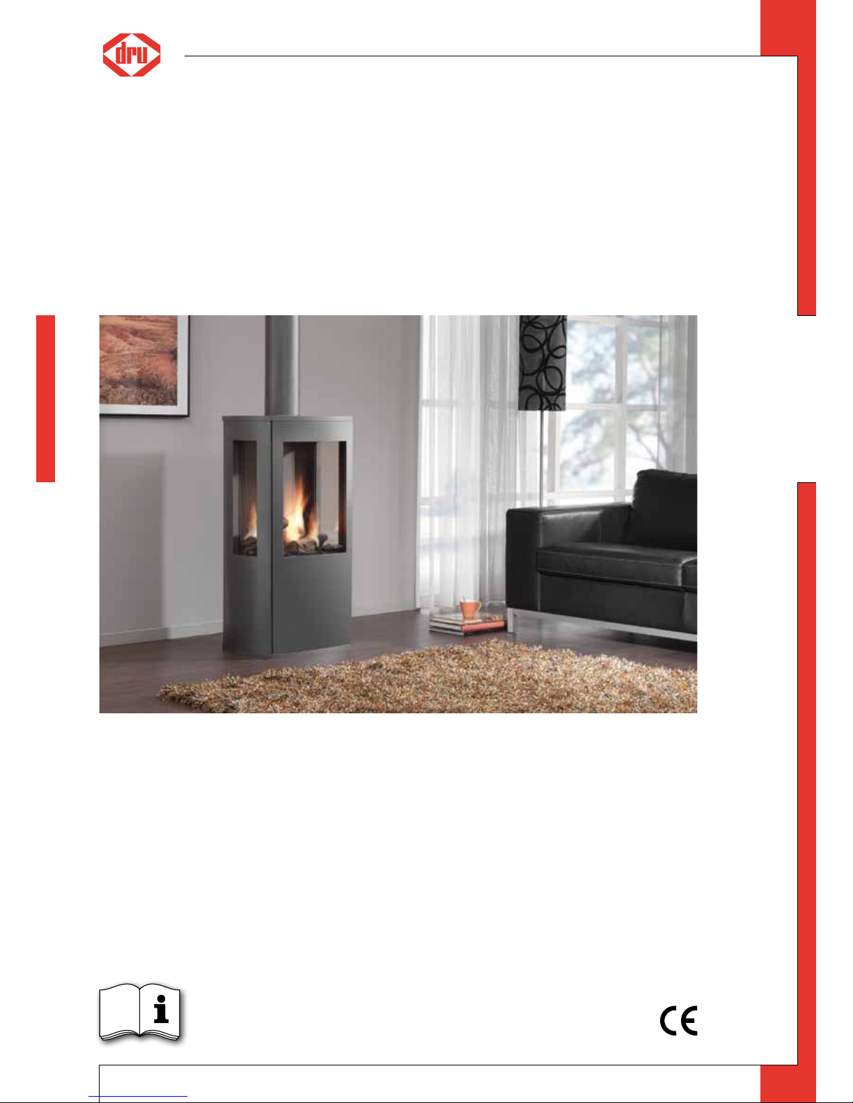
Trio
G31 Propane
Please retain this document carefully
Instructions for installation (GB / IE)
959.065.01.UK
UK

2
English
t ri o - in s tr u ct i on fo r i ns ta l la ti on
Contents
page
Preface 2
1. Introduction 3
2. CE Declaration 3
3. SAFETY 3
3.1 General 3
3.2 Regulations 3
3.3 Precautions / safety instructions during installation 3
4. Instructions 4
5. Removing the packaging 4
6. Installation 4
6.1 Regulations 4
6.2 Type of gas 4
6.3 Gas connection 4
6.4 Placement of the appliance 4
6.5 Flue gas discharge / combustion air supply system 5
6.6 Connecting gas 8
6.7 Setting the appliance 8
6.8 Placing the wood set 8
6.9 Panes 9
7. Wireless remote control 10
7.1 Receiver 10
7.2 Setting the communication code 10
7.3 Alternative operation 11
8. Final check 11
8.1 Gastightness 11
8.2 Gas pressure / pre-pressure 11
8.3 Ignition pilot and main burner 11
8.4 Flame picture 12
9. Maintenance 12
10 Delivery 13
11. Malfunctions 14
Appendix 1 Parts included with the delivery 17
Appendix 2 Technical data 17
Appendix 3 Parts 17
Appendix 4 Figures 18
Preface
DRU, a manufacturer of gas heating appliances, develops and produces products that comply with the highest quality, performance and safety requirements.
This guarantees that the user will be able to enjoy using his product for many years to come.
This appliance has a CE marking, which means that it complies with the essential requirements of the European gas
appliance directive.
As an installer, you must be competent in the field of atmospheric gas heating.
Two manuals are supplied with the appliance: the installation manual and the user manual.
The installation manual will give you the information you need to install the appliance in such a way that it will operate properly and safely.
This manual discusses the installation of the appliance and the regulations that apply to the installation. In addition,
you will find technical data for the appliance and information on maintenance, any malfunctions that might occur
and their possible causes.
Please carefully read and use this installation manual.
The following symbols are used in the manual to indicate important information:
➠
Work to be performed
!Tip
Suggestions and recommendations
!Caution
You will need these instructions to prevent problems that might occur during installation and/or use.
Caution
You need these instructions to prevent re, personal injury or other serious damages.
After delivery, you should give the user manual and this installation manual to the user.
UK
3
English
t ri o - in s tr u ct i on fo r i ns ta l la ti on
1. Introduction
The Trio is a freestanding atmospheric gas heating appliance. This version of the Trio is suitable for propane. It is not
possible to make the appliance suitable for a different type of gas by using a so-called conversion set.
The Trio is a closed appliance. A closed appliance does not extract the combustion air from the living environment,
but from outside. This is done through a combined flue gas discharge system / combustion air supply system. In
this concentric system the outer pipe serves as air supply and the inner pipe as flue gas discharge.
This system can be installed through the wall, or through the roof.
The concentric system can be supplied in the colour of the appliance.
The appliance is supplied with a wireless remote control that works on batteries.
2. CE Declaration
We hereby declare, that the design and construction method of the gas-fired heating appliance issued by Dru
complies with the essential requirements of the gas appliance directive.
Product: gas-fired heating appliance
Type: Trio
EEC directives: 2009/142/EC
Standards: NEN-EN-613
NEN-EN-613/A1
Internal precautions at the company will guarantee that appliances produced in series comply with the essential
requirements of the EC directives in force and the standards derived from them. This declaration will lose its validity
if adjustments are made to the appliance, without prior written permission by DRU.
You will be able to download a copy of the test certificate via www.druservice.com.
M.J.M. Gelten
General manager
Postbus 1021, 6920 BA Duiven
Ratio 8, 6921 RW Duiven
www.dru.nl
3. SAFETY
3.1 General
Caution
- Carefully read this chapter on safety, before you start performing installation or maintenance work;
- Please observe the general regulations and the precautions/safety instructions in this manual.
3.2 Regulations
Please install the appliance in accordance with the applicable national, local and constructional (installation) regulations.
3.3 Precautions / safety instructions during installation
Carefully follow the following precautions/safety regulations:
➠
you should only install and maintain the appliance if you are a competent installer in the eld of atmospheric gas heating;
➠
do not make any changes to the appliance;
➠
only use the ue gas discharge / combustion air supply system supplied by DRU;
➠
place the appliance at a distance of at least 40 mm from the back wall;
➠
do not cover the appliance and the discharge material and/or do not wrap it in an insulation blanket or any other material;
➠
always place the appliance and/or the discharge pipes at a minimum distance of 500 mm from combustible objects or
materials;
➠
only ever use the supplied wood set;
➠
place the wood set exactly as described;
➠
make sure the pilot burner and the space around it is kept free;
➠
avoid dirt in gas pipes and connections;
➠
check the connections for gastightness before using the appliance;
➠
avoid blocking of the pressure equalization hatch on top of the appliance;
➠
check whether the pressure equalization hatch ts well onto the sealing surface;
➠
do not ignite the appliance until it is fully installed;
➠
replace torn or broken panes.
UK
4
English
t ri o - in s tr u ct i on fo r i ns ta l la ti on
!Caution
- In case of broken or torn glass panes, the application may not be used.
- Protect the appliance against dust and moisture created during the building process!
4. Instructions
Observe the following items during installation in order to guarantee a proper and safe operation of the appliance:
➠
avoid that the ignition cable runs over and/or alongside metal parts, in order to prevent weakening of the spark;
➠
avoid damaging the panes during removal/placing;
➠
clean the panes before you use the appliance, in order to prevent dirt from burning in the glass.
5. Removing the packaging
Note the following items when removing the packaging:
➠
remove all packaging materials
➠
Check the appliance for damages during transport;
➠
If necessary, contact DRU Service;
➠
Take the parts box and the wood set from the space behind the door at the bottom of the appliance.
In appendix 1 / table 5 you can see which parts you should have after removing the packaging.
➠
Remove both woodscrews from the bottom plate connecting the appliance to the platform.
Caution
Heat-resistant glass is a ceramic material. Very small irregularities in the glass pane(s) cannot be avoided, but are wit-
hin the required quality standards.
!Caution
Keep plastic bags away from children.
➠
Contact DRU Service if you do not have all the parts after you nished removing the packaging;
➠
Dispose packaging in accordance with local regulations.
6. Installation
Read this manual carefully to ensure a proper and safe operation of the appliance.
!Caution
Install the appliance in the order described in this chapter.
6.1 Regulations
- Please install the appliance in accordance with the applicable national, local and constructional (installation)
regulations;
- Observe the regulations/instructions in this manual.
6.2 Type of gas
The type plate indicates for which type of gas, gas pressure and for which country this appliance is intended. The type
plate can be found behind the door on the back wall of the space at the bottom of the appliance.
Caution
- Check whether the appliance is suitable for the type of gas and the gas pressure used at the location.
- Do not make any changes to the appliance.
6.3 Gas connection
Place a gas tap in the gas connection, close to the appliance.
Caution
Avoid dirt in the gas pipe and in the connections.
The following requirements apply to the gas connection:
- use a gas pipe with the correct dimensions, so that no pressure loss can occur:
- the gas tap must be approved (in the EU this will be the CE mark);
- you should always be able to reach the gas tap.
6.4 Placement of the appliance
Place the appliance as follows:
Caution
- Always place the appliance and/or the discharge pipes at a minimum distance of 500 mm from combustible objects
or materials;
➠
Determine the location of the appliance; the dimensions can be found in Fig. 1, see Appendix 4;
➠
Provide a gas connection at the location. For details, see section 6.3;
➠
Make a duct for the ue gas discharge/combustion air supply system with the following diameters. For details, see
section 6.5.
UK
5
English
t ri o - in s tr u ct i on fo r i ns ta l la ti on
- Ø160 mm for a wall duct through incombustible material;
- Ø 250 mm for a wall duct through combustible material;
- Ø160 mm for a roof duct through incombustible material;
- Ø 250 mm for a roof duct through combustible material.
➠
Place the appliance on its destined location.
Caution
- Place the appliance at a distance of at least 40 mm from the back wall;
- Do not cover the appliance and the discharge material and/or do not wrap it in an insulation blanket or any other
material.
6.5 Flue gas discharge / combustion air supply system
6.5.1 General
The appliance is of the C11/C31/C91 type.
The appliance is connected to a combined flue gas discharge/combustion air supply system, hereafter referred to
as the concentric system.
The passage to the outside can be made with a wall duct (see section 6.5.2) or with a roof duct (see section 6.5.3).
If necessary, you can also use an existing discharge channel (see section 6.5.4).
Caution
- Only use the concentric system supplied by DRU (Ø100 / Ø150 mm). This system was tested in combination with the
appliance; DRU cannot guarantee a proper and safe operation of other systems and cannot accept liability for these
systems;
- For connecting to an existing chimney ue you should only use the installation set supplied by DRU.
The concentric system is constructed from (the discharge stump of) the appliance.
If structural circumstances require that the concentric system is placed first, the appliance can later be connected
with a telescopic pipe piece.
!Tip
DRU does not recommend placing the telescopic piece, because this visible pipe piece cannot be supplied in colour
and does not really combine well with the appliance.
6.5.2 Application with wall duct
6.5.2.1 Construction of concentric system with wall duct
The concentric system with wall duct has to comply with the following conditions (see Appendix 4, Fig. 2):
- First, a concentric pipe of at least 1 meter should be connected vertically to the appliance;
- The total vertical pipe length can have a maximum of 4 meters;
- On the vertical part a bend of 90° is connected;
- Only wall ducts are allowed.
Under these conditions you should not install the restrictor slide.
6.5.2.2 Placing concentric system with wall duct
Place the concentric system as follows:
➠
Build the system up from (the connection stump of ) the appliance.
Caution
- Maintain a distance of at least 50 mm between the outside of the concentric system and the walls and/or the ceiling;
- Use heat-resistant isolation material when passing through combustible material;
- The rosette (mounting inner plate) of the wall duct is too small to seal the Ø 250 mm opening when passing through
combustible material. That is why you should rst apply a suciently large heat-resistant intermediate plate to the
wall. Then, the rosette is mounted on the intermediate plate.
!Caution
Some heat-resistant isolation materials contain volatile components that will spread an unpleasant smell for a pro-
longed time; these are not suitable.
➠
Remove the top plate from the appliance; this plate is loose;
➠
Remove the cover plate by unscrewing the 2 parkers (see Appendix 4, Fig. 3);
➠
Place a lacquered pipe piece on the appliance;
➠
Apply a lacquered clip binding with silicon sealing ring onto the connection between appliance and pipe piece;
➠
Ret the cover plate with the 2 parkers;
➠
Place the top plate carefully onto the appliance, so that the lacquered pipe piece will not be damaged;
➠
If necessary, connect the vertical (lacquered) concentric pipe pieces;
➠
Connect the lacquered bend;
➠
If necessary, connect the horizontal (lacquered) concentric pipe pieces;
➠
On each connection, apply a (lacquered) clip binding with silicon sealing ring;
➠
Use a parker to x the clip binding to the pipe on locations that are unreachable after installation;
➠
Apply sucient clamps, so that the weight of the pipes does not only rest on the appliance;
➠
Determine the remaining length of the wall duct;
➠
Make sure the wall duct has the right dimensions.
UK

6
English
t ri o - in s tr u ct i on fo r i ns ta l la ti on
!Caution
- Make sure that the right insertion length is maintained;
- Place the wall duct with the groove/folded seam at the top;
- Make sure the horizontal concentric pipe pieces are sloping towards the wall duct, in order to prevent rain water
from entering.
➠
Mount the rosette (mounting inner plate); if necessary, on a heat resistant intermediate plate when passing through
combustible material;
➠
Attach the wall duct from the outside with four screws in their respective holes.
6.5.3 Application with roof duct
6.5.3.1 Construction of concentric system with roof duct
The concentric system with roof duct has to comply with the following conditions:
- The construction of the chosen system has to be allowed. (See the procedure described below);
- First, a concentric pipe of at least 1 meter should be connected vertically to the appliance.
Depending on the construction, the appliance is set by means of the baffle and/or the air inlet guide.
In the following procedure you can see how the allowability of a concentric system can be determined and which
settings are needed.
➠
Determine the following data:
1) The number of bends required (no distinction is made between 45° and 90° bends);
2) The total number of meters of horizontal pipe length;
3) The total number of meters of vertical and/or sloping pipe length.
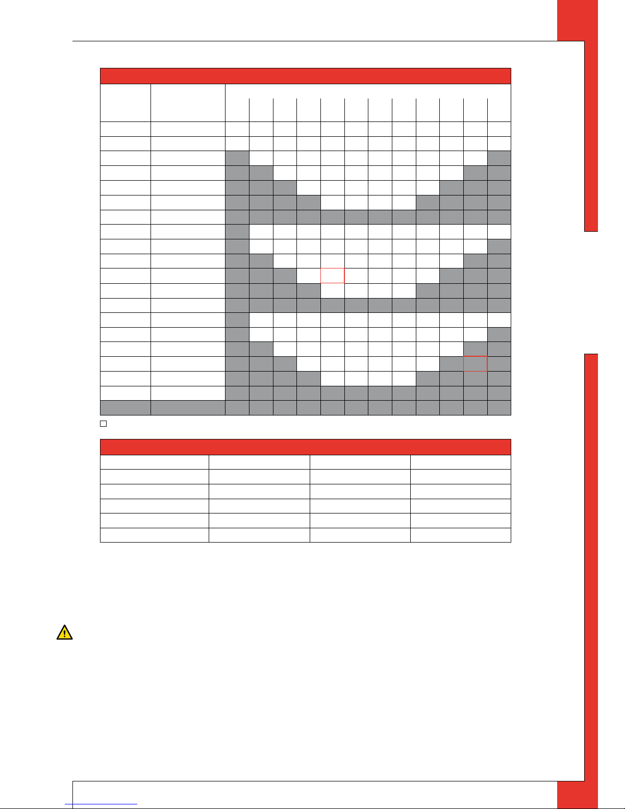
These data will help you determine whether the concentric system is allowed by using Table 1
In Table 2 you can read which setting is required for the appliance.
Follow the procedure described below:
➠
In the rst 2 columns of Table 1, search the number of bends required and the total horizontal pipe length:
➠
In the 3rd column of Table 1/Table 3, search the total vertical and/or sloping pipe length.
If you end up in a box with the letter A, B, C, D or E, the concentric system chosen by you is allowed.
➠
Use Table 2 to determine which conditions apply for the bae and/or the air inlet guide (for placing/setting see section 6.7).
Examples
To clarify, we will give 2 examples to determine the acceptability of a concentric system and the conditions for setting
the appliance. In Table 1 the route to be followed is indicated by arrows. The result is outlined in red.
Example 1
1) 3 bends
2) 3 metres horizontal
3) 5 metres vertical/sloping
→ Construction of this concentric system is allowed.
→ Situation A applies to the adjustment of the appliance.
Example 2
1) 4 bends
2) 3 metres horizontal
3) 11 metres vertical/sloping
→ Construction of this concentric system is not allowed.
UK
7
English
t ri o - in s tr u ct i on fo r i ns ta l la ti on
Table 1: Relation construction concentric system / setting appliance
G31
total number of
meters horizontal
pipe length
total number of meters vertical and/or sloping pipe length
1 2 3 4
↓5
6 7 8 9 10
↓11
12
no bends 0 B C C D D D D E E E E E
2 bends 0 A A B C C D D D D E E E
1 A A B C C D D D D E
2 A A B C C D D D
3 A A B C C D
4 A A B C
5
3 bends 0 A A B C C D D D D E E
1 A A A B C C D D D D
2 A A A B C C D D
→
3 A A A B C C
4 A A A B
5
4 bends 0 A A A B C C D D D D E
1 A A A A B C C D D D
2 A A A A B C C D
→
3 A A A A B C
4 A A A A
5
5 bends -
n = construction is not allowed
Table 2: Conditions for setting the appliance
Situation Air inlet guide Baffle Distance restriction
A NO YES 60 mm
B NO YES 48 mm
C NO YES 43 mm
D NO YES 38 mm
E NO YES 33 mm
6.5.3.2 Placing concentric system with roof duct
The roof duct can end in a sloping and a flat roof.
The roof duct can be supplied with an adhesive plate for a flat roof or with a universally adjustable tile for a sloping
roof.
Place the concentric system as follows:
➠
Build the system up from (the connection stump of ) the appliance.
Caution
- Maintain a distance of at least 50 mm between the outside of the concentric system and the walls and/or the ceiling;
- Use heat-resistant isolation material when passing through combustible material.
!Caution
Some heat-resistant isolation materials contain volatile components that will spread an unpleasant smell for a pro-
longed time; these are not suitable.
➠
Remove the top plate from the appliance; this plate is loose;
➠
Remove the cover plate by unscrewing the 2 parkers (see Appendix 4, Fig. 3);
➠
Place a lacquered pipe piece on the appliance;
➠
Apply a lacquered clip binding with silicon sealing ring onto the connection between appliance and pipe piece;
➠
Ret the cover plate with the 2 parkers;
➠
Place the top plate carefully onto the appliance, so that the lacquered pipe piece will not be damaged;
➠
Connect the horizontal (lacquered) concentric pipe pieces and, if necessary, the bends;
➠
On each connection, apply a (lacquered) clip binding with silicon sealing ring;
UK

8
English
t ri o - in s tr u ct i on fo r i ns ta l la ti on
➠
Use a parker to x the clip binding to the pipe on locations that are unreachable after installation;
➠
Apply sucient clamps, so that the weight of the pipes does not only rest on the appliance;
➠
Determine the remaining length of the roof duct;
➠
Make sure the roof duct has the right dimensions.
!Caution
Make sure that the right insertion length is maintained.
➠
Connect the roof duct to the concentric pipes.
!Caution
- Make sure that the universal tile ts well with the surrounding tiles;
- Make sure that the adhesive plate ts well onto the at roof.
6.5.4 Connection of existing chimney flue
It is possible to connect the appliance to an existing channel.
A flexible SS pipe is placed in the chimney for discharging flue gases. The surrounding space is used to supply
combustion air.
The following requirements apply when connecting to an existing chimney flue:
- only allowed when used in combination with the special DRU chimney installation set.
The installation regulation is also supplied;
- the dimensions should be at least 150 x 150 mm;
- the vertical length has a maximum of 12 meters;
- the horizontal length has a maximum of 3 meters;
- the existing chimney flue has to be clean;
- the existing chimney flue has to be closed.
For adjusting the appliance, the same conditions/instructions apply as for the concentric system described above.
6.6 Connecting gas
Use the following procedure when connecting the gas, see section 6.3 Gas connection:
➠
If necessary, blow through the gas pipe;
➠
Connect the gas pipe with gas tap to the gas control block.
!Caution
- You can nd the gas control block behind the door in the space at the bottom of the appliance;
- Do not turn the gas tap when connecting the gas pipe.
➠
Bleed the gas pipe.
6.7 Setting the appliance
The appliance has to be set in such a way that is works correctly in combination with the discharge system.
For that purpose it is possible to install a baffle. For the conditions, see section 6.5.2.1, for application with wall duct
and section 6.5.3.1, Table 2, for application with roof duct.
6.7.1 Baffle (R)
!Caution
The restrictor slide should be placed in the correct manner. Therefore, accurately observe the instructions
The baffle (R) is supplied separately.
Follow the procedure below when placing the baffle:
➠
Remove the front pane as indicated in section 6.9.1;
➠
Place the bae (see Appendix 4, Fig. 4);
➠
Use the template supplied to set the distance of the restriction (see Appendix 4, Fig. 5) as follows:
- A distance of 33 mm means that the bae is closed to a maximum level;
- A distance of 38, 43, 48 and 60 mm is set by means of a template.
➠
Fix the bae by using the socket cap screw (S).
6.8 Placing the wood set
The appliance is supplied with a wood set.
Caution
Strictly observe the following instructions to prevent unsafe situations:
- only ever use the supplied wood set;
- place the wood set exactly as described;
- make sure the pilot burner and the space around it are kept free from objects (
see Appendix 4, Fig. 6);
- make sure that the slot between the burner tray and the tray surrounding the burner is kept free from objects.
- make sure that the vermiculite’s ne dust does not get on the burners.
UK
 Loading...