

Page 1
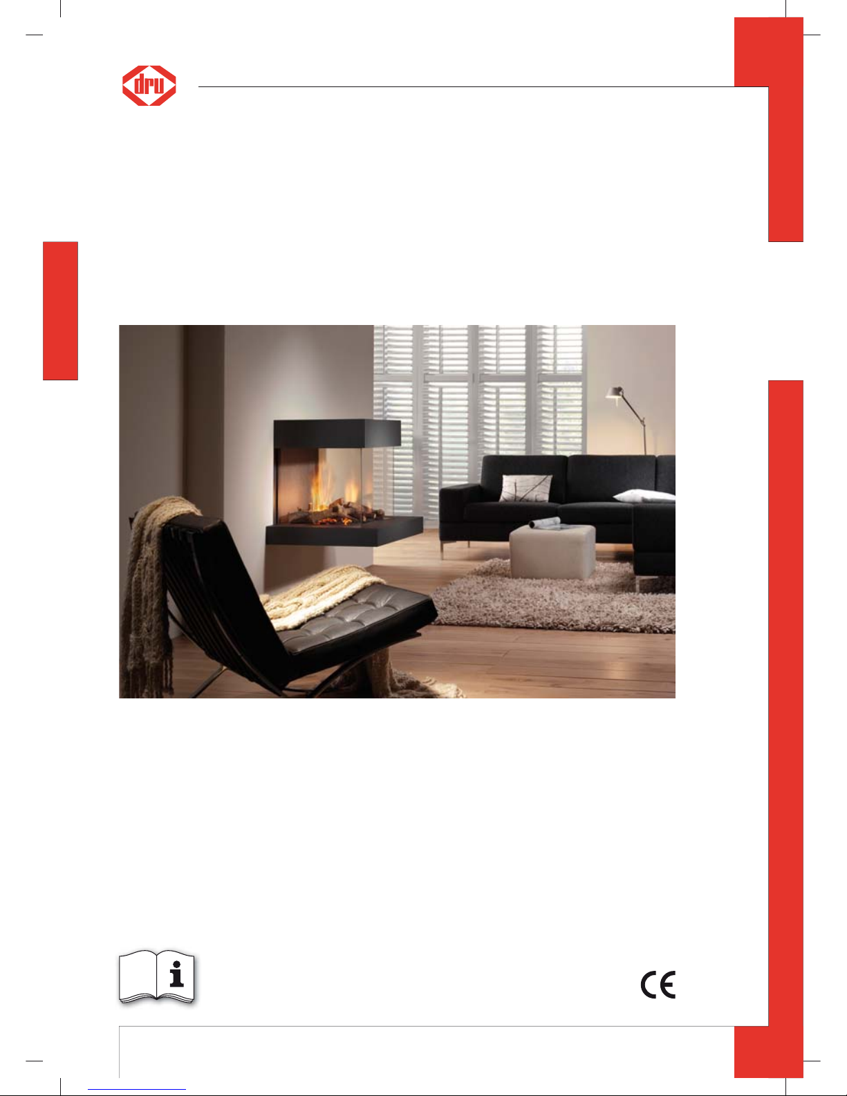
English
Store this document in a safe place
Milo
Installation manual (GB / IE)
959.028.01.GB
G20/G25/G31
GB
95902801_GB Install.indd 195902801_GB Install.indd 1 12-7-10 11:212-7-10 11:2
Page 2
2
MILO INSTALLATION MANUAL
English
Contents
page
Preface 3
1. Introduction 3
2. CE declaration 4
3. SAFETY 4
3.1 General 5
3.2 Regulations 5
3.3 Precautions / safety instructions during installation 5
4. Instructions 6
5. Removing the packaging 6
6. Installation 6
6.1 Regulations 6
6.2 Type of gas 6
6.3 Gas connection 6
6.4 Placing the appliance 6
6.5 Flue gas discharge / combustion air supply system 6
6.6 Placing the chimney breast 12
6.7 Connecting gas 13
6.8 Adjusting the appliance 13
6.9 Placing the wood set 14
6.10 Glass panes 15
6.11 Finishing the appliance 16
7. Wireless remote control 17
7.1 Receiver 17
8. Final check 17
8.1 Gastightness 17
8.2 Gas pressure / line-pressure 17
8.3 Ignition pilot burner and main burners 17
8.4 Flame image 18
9. Maintenance 18
9.1 Parts 19
10. Delivery 19
11. Malfunctions 19
Appendix 1 Parts included with the delivery 23
Appendix 2 Technical data 23
Appendix 3 Figures 24
Appendix 4 Figures 36
GB
95902801_GB Install.indd 295902801_GB Install.indd 2 12-7-10 11:212-7-10 11:2
Page 3
3
MILO INSTALLATION MANUAL
English
Preface
DRU, a manufacturer of gas- red heating appliances, develops and produces products that comply with the highest
quality, performance and safety requirements.
This guarantees that the user will be able to enjoy using his product for many years to come.
This appliance has a CE marking, which means that it complies with the essential requirements of the European gas
appliance directive.
Two manuals are supplied with the appliance: the installation manual and the user manual.
As an installer, you must be competent in the eld of atmospheric gas- red heating.
The installation manual will give you the information you need to install the appliance in such a way that it will operate properly and safely.
This manual discusses the installation of the appliance and the regulations that apply to the installation. In addition,
you will nd technical data for the appliance and information on maintenance, any malfunctions that might occur
and their possible causes.
The gures are included at the back of this booklet (Appendix 3).
Please carefully read and use this installation manual.
The following symbols are used in the manual to indicate important information:
➠
Work to be performed
!Tip
Suggestions and recommendations
!Caution
You will need these instructions to prevent problems that might occur during installation and/or use.
Caution
You need these instructions to prevent re, personal injury or other serious damages.
Af ter delivery, you should give the user manual and this installation manual to the user.
1. Introduction
Milo is a suspended atmospheric gas- red heating appliance. It is xed to the wall by means of a supplied wall
bracket. In order to support it, the appliance is standing on 2 adjustable legs at the rear.
The safe operation of the appliance is guaranteed by the use of a second thermocouple tted to one of the main
burners.
Milo is a room-sealed appliance. A room-sealed appliance does not extract the combustion air from the living environment, but from outside. This is done by means of a combined ue gas discharge system / combustion air supply
system. In this concentric system, the outer pipe functions as the air supply and the inner pipe functions as the ue
gas discharge.
Milo has a rectangular ( at), concentric ue spigot. Both a rectangular and round concentric system can be connected to this. DRU has a number of adapters in its range for the transition from rectangular to round.
The concentric ue gas discharge / combustion air supply system can be installed through the wall or through the
roof.
Milo was designed to suspend freely. The narrow chimney breast at the rear of the appliance is only intended to hide
the ue gas discharge / combustion air supply system and the adjustable legs.
Construction in a standard chimney breast, the construction chimney breast, is allowed. In that case, a mantel iron
must be placed, in order to avoid that the appliance is burdened by the weight of the construction chimney breast.
DRU is able to supply a mantel iron. Also make sure that the gas control and receiver, which are below the appliance,
can still be reached after placing the construction chimney breast.
The chimney breast may only be made of plate material.
In order to reach a proper heat discharge, the chimney breast must be ventilated at both sides, and an air supply
must be made at the bottom. DRU has various ventilation elements in its program; the lux no elements can be
specially supplied for the narrow chimney breast.
A base (platform) will be placed around the appliance. The choice of a natural stone or lacquered steel version was
made during purchase. The construction of the appliance was based on the weight of the DRU base. If you want to
extend the base supplied by DRU, you will need an additional bearing construction.
The appliances are supplied with a wireless remote control that works on batteries.
GB
95902801_GB Install.indd 395902801_GB Install.indd 3 12-7-10 11:212-7-10 11:2
Page 4
4
MILO INSTALLATION MANUAL
English
2. CE declaration
We hereby declare that the design and construction of DRU’s atmospheric gas- red heating appliance comply with
the essential requirements of the Gas Appliance Directive.
Product: atmospheric gas- red heating appliance
Type: Milo
Applicable EEC directives: 2009/142/EC
Applied harmonized standards: NEN-EN-613
NEN-EN-613/A1
Internal measures by the company guarantee that appliances produced in series comply with the essential requirements of the prevailing EEC directives and the standards derived from them.
This declaration will lose its validity if adjustments are made to the appliance, without prior written permission by
DRU.
M.J.M. Gelten
General manager
DRU verwarming B.V.
Postbus 1021, 6920 BA Duiven
Ratio 8, 6921 RW Duiven
www.dru.nl
3. SAFETY
3.1 General
Caution
- Carefully read this chapter on safety, before you start performing installation or maintenance work;
- P lease observe the general regulations and the precautions/safety instructions in this manual.
3.2 Regulations
Please install the appliance in accordance with the applicable national, local and constructional (installation) regulations.
3.3 Precautions / safety instructions during installation
Carefully observe the following precautions/safety regulations:
➠
you should only install and maintain the appliance if you are a competent installer in the eld of atmospheric gas- red
heating;
➠
do not make any changes to the appliance;
➠
use solid, non combustible and heat-resistant materials for the wall from which the appliance will be suspended;
➠
always use the adjustable legs to support the appliance;
➠
use non combustible and heat-resistant plate material for the chimney breast, including the top of the chimney breast
and the material in the chimney breast;
➠
take su cient measures to prevent temperatures of a wall behind the chimney breast becoming too high, including
the materials and/or objects behind the wall;
➠
ventilate the chimney breast at both sides by means of the ventilation holes, which will form a combined passage of at
least 200cm
2
;
➠
attach an additional air supply at the bottom of the chimney breast;
➠
in case of a narrow chimney breast, maintain a tolerance of approx. 2mm between plate material and construction
frame;
➠
comply with the minimum required internal measurements, in case of a construction chimney breast;
➠
comply with the minimum required free space of 500mm at both sides of the appliance, as well as above the appliance,
because of the heat emission of the appliance;
➠
only use the ue gas discharge / combustion air supply system supplied by DRU;
➠
mount the appliance using the wall bracket supplied;
➠
do not suspend the appliance too close to the wall; this is prevented by using the spacer brackets;
➠
do not cover the appliance and/or do not wrap it in an insulation blanket or any other material;
➠
make sure that combustible objects and/or materials have a distance from the appliance of at least 500mm
➠
only ever use the supplied wood set;
➠
place the wood set exactly as described;
➠
make sure the pilot burner and the space around it is kept free;
➠
make sure thermocouple2 and the space around it are kept free;
➠
make sure there is no dirt in gas pipes and connections;
➠
place a gas tap near the appliance;
GB
95902801_GB Install.indd 495902801_GB Install.indd 4 12-7-10 11:2412-7-10 11:24
Page 5
5
MILO INSTALLATION MANUAL
English
➠
check the connections for gastightness before using the appliance;
➠
use heat resistant electrical wiring;
➠
place the electrical wiring in such a way that they are free from the appliance;
➠
replace torn or broken glass panes;
➠
avoid blocking of the pressure equalization hatch(es) on top of the appliance;
➠
check whether the pressure equalization hatch(es) t well onto the sealing surface, prior to building in the appliance;
➠
do not ignite the appliance until it is fully installed.
4. Instructions
Observe the following items during installation in order to guarantee a proper and safe operation of the appliance:
➠
place the spacer brackets in correspondence with the construction depth of the appliance. The construction depth
depends on whether a rectangular or round ue gas discharge / combustion air supply system was chosen. During
manufacturing, the spacer brackets are placed for application of a rectangular system;
➠
avoid that the ignition cable runs over the receiver;
➠
avoid that the ignition cable touches or crosses the antenna;
➠
avoid that the ignition cable runs alongside metal parts, in order to prevent weakening of the spark;
➠
avoid damaging the glass panes when removing/placing them;
➠
clean the glass panes before you use the appliance, in order to prevent dirt from burning in the glass;
➠
make sure that the wires of thermocouple 2 cannot come into contact with hot parts.
5. Removing the packaging
Note the following items when removing the packaging:
➠
Check the appliance for damages during transport.
➠
If necessary, contact DRU Service.
!Caution
Avoid damaging the front glass pane when removing it from the packaging.
After removing the packaging, you should have the following components:
- Socket spanner; you will nd it in the space between the assembly frame and the combustion chamber;
- Decorative strips; you will nd them in the abovementioned space as well;
- Front glass pane; you will nd it in the same box as the appliance – provided with protective corners;
- Box containing parts; you will nd it in the combustion chamber;
- Inner frame; consisting of a lacquered steel frame or a four part set of natural stone;
- Base; made of lacquered steel or natural stone;
- Top; intended for the top of the appliance.
➠
Remove the box containing parts from the combustion chamber.
In appendix 1 / table 5 you can see which parts you should have after removing the packaging.
➠
Contact DRU Service if you do not have all the parts after you nished removing the packaging.
➠
Dispose packaging in accordance with local regulations.
GB
95902801_GB Install.indd 595902801_GB Install.indd 5 12-7-10 11:2412-7-10 11:24
Page 6
6
MILO INSTALLATION MANUAL
English
6. Installation
Read this manual carefully to ensure a proper and safe operation of the appliance.
!Caution
Install the appliance in the order described in this chapter.
6.1 Regulations
➠
Observe the applicable (installation) regulations.
➠
Observe the regulations/instructions in this manual.
6.2 Type of gas
The data plate indicates for which type of gas, gas pressure and for which country this appliance is intended. The
data plate is connected to a chain. It should remain connected to the chain.
Caution
Check whether the appliance is suitable for the type of gas and the gas pressure used at the location.
6.3 Gas connection
Place a gas tap in the gas connection, close to the appliance.
Caution
Make sure there is no dirt in gas pipes and connections.
The following requirements apply to the gas connection:
- use a gas pipe with the correct dimensions, so that no pressure loss can occur;
- the gas tap should have the CE marking;
- you sh ould always be able to reach the gas tap.
6.4 Placing the appliance
Caution
- Attach the appliance to a wall of solid, non combustible and heat-resistant material;
- Always use the adjustable legs to support the appliance;
- Take su cient measures to prevent temperatures of a wall behind the chimney breast becoming too high,
- including the materials and/or objects behind the wall;
- Comply with the minimum required free space of 500mm at both sides of the appliance, as well as above the
appliance, because of the heat emission of the appliance;
- Make sure that combustible objects and/or materials have a distance from the appliance of at least 500mm;
- Do not suspend the appliance too close to the wall; this is prevented by using the spacer brackets
- Level the appliance horizontally and vertically, using the adjustable feet and adjustment bolts;
- Do not cover the appliance and/or do not wrap it in an insulation blanket or any other material;
- Do not make any changes to the appliance.
!Caution
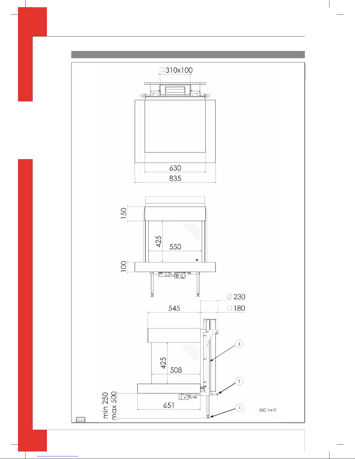
- Take the adjustable height of the appliance into account. It depends on the setting of the adjustable legs: minimum
250 and maximum 500mm (see g.1);
➠
Take the minimum internal depth of the appliance into account (see g.1).
!Tip
During manufacture, the spacer brackets on the appliance are mounted for the application of the rectangular ue
gas discharge / combustion air supply system.
Place the appliance as follows:
➠
Determine the location of the appliance.
➠
Determine the suspension height of the appliance; see g.1;
➠
Provide a gas connection at the location. For details, see section 6.3.
➠
Determine whether a rectangular or round ue gas discharge / combustion air supply system will be connected to the
appliance’s ue spigot; see g.1.
➠
Make a passage for the ue gas discharge/combustion air supply system with the following diameters. For details,
see section 6.5:
- Ø 160 mm for a wall terminal through non combustible material;
- Ø 250 mm for a wall terminal through combustible material;
- Ø 160 mm for a roof terminal through non combustible material;
- Ø 250 mm for a roof terminal through combustible material.
➠
Place the appliance on its destined location.
➠
When leading the rectangular ue gas discharge / combustion air supply system through a oor and/or ceiling, take
the following dimensions into account; for details see section 6.5:
GB
95902801_GB Install.indd 695902801_GB Install.indd 6 12-7-10 11:2412-7-10 11:24
Page 7
7
MILO INSTALLATION MANUAL
English
- 350x140mm through non combustible material;
- 430x220mm through combustible material.
➠
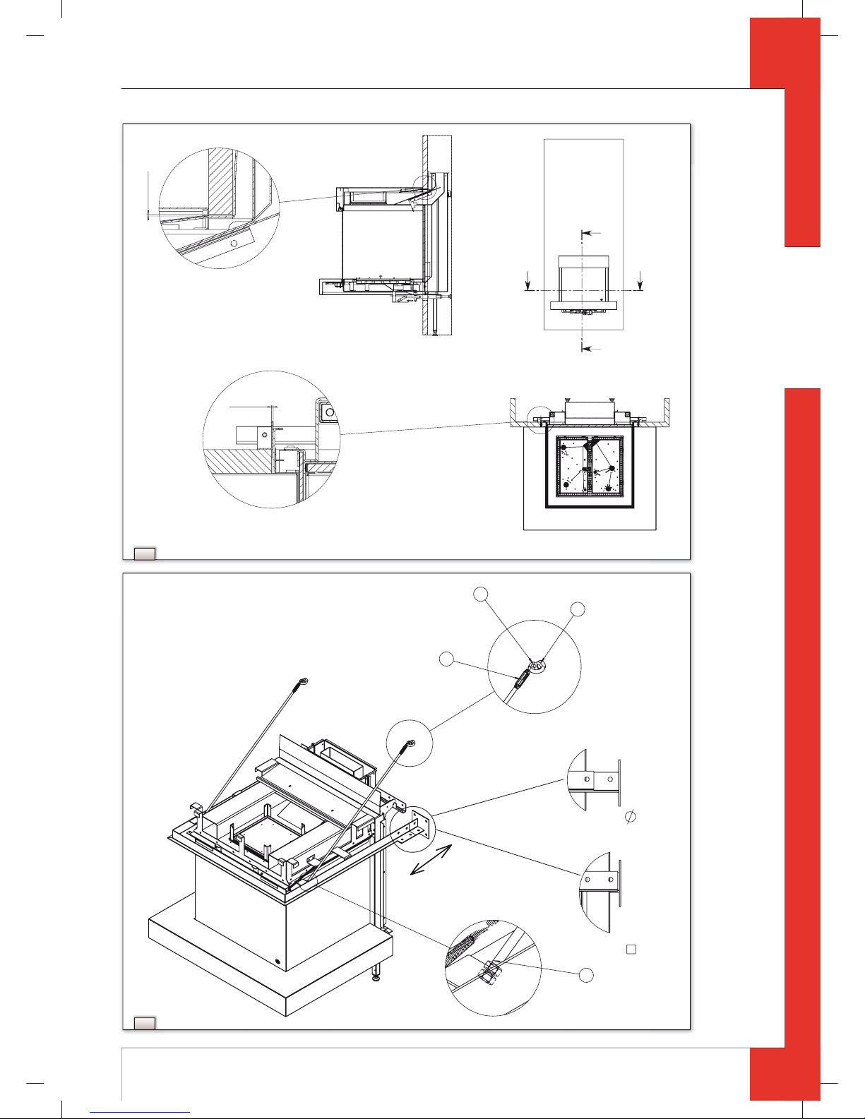
Check whether the position of the spacer brackets on the appliance is suitable for the chosen rectangular (A) or
round(B) ue gas discharge / combustion air supply system; see g.2.
➠
Loosen the screws of the spacer brackets (C) and turn the brackets around when a round system is used; see g.2.
➠
Mount the appliance using the wall bracket and the key bolts supplied.
➠
Extend both adjustable legs and secure them with a self-tapping screw.
➠
Use the feet of the adjustable legs to level the appliance horizontally; see g.1, arrow1.
➠
Use the adjustment bolts to level the appliance vertically; see g.1, arrow2.
6.5 Flue gas discharge / combustion air supply system
6.5.1 General
The appliance is of the C11/C31 type.
The appliance is connected to a combined ue gas discharge/combustion air supply system, hereafter referred to as
the concentric system.
The ue spigot of the appliance, is a rectangular, concentric version. To this you can connect a rectangular (A) (310x100
/ 205x55mm) and/or round (B) (Ø100 / Ø150mm) concentric system; see g.3a.
The passage to the outside can be made with a wall terminal (see section 6.5.2) or a roof terminal (see section 6.5.3).
If necessary, you can also use an existing chimney (see section 6.5.4).
Caution
- Only use the rectangular and/or round concentric system supplied by DRU. This system has been tested together with
the appliance. DRU cannot guarantee a proper and safe operation of other systems and does not accept any liability
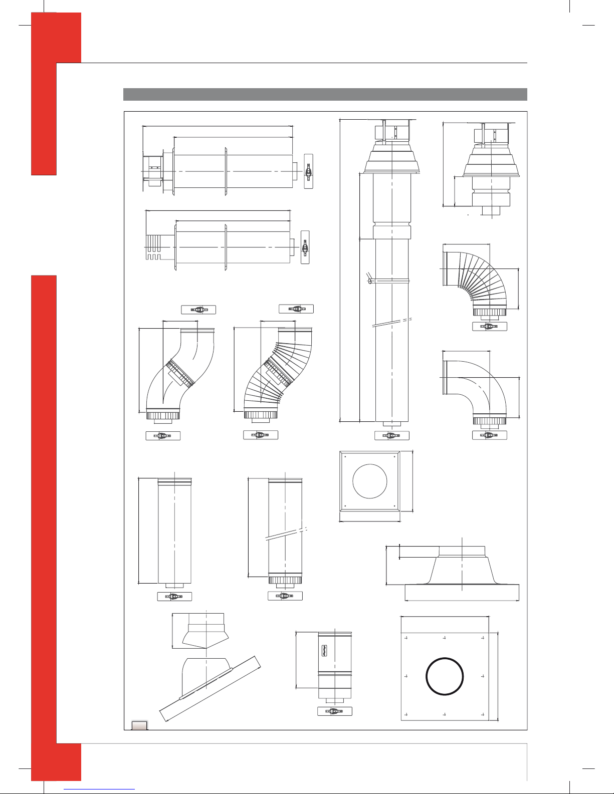
for this (see appendix 4);
- Always use coupling pieces with corresponding seals for the connections in the rectangular system. These are
supplied with the system; see the accompanying instructions;
- Secure the coupling pieces with the self-tapping screws supplied;
- For connecting to an existing chimney you should only use the chimney kit supplied by DRU.
The concentric system is constructed from ( ue spigot of ) the appliance.
If structural circumstances requir e that the concentric system is placed rst, the appliance can later be connected
with a telescopic pipe piece, provided a round concentric system is used. In that case, an adapter to round must rst
be placed on the ue spigot. It is not possible to supply a telescopic pipe piece for a rectangular concentric system.
6.5.2 Application with wall terminal
The wall terminal is a round conce ntric system.
6.5.2.1 Construction of concentric system with wall terminal
!Caution
- When using rectangular pipes it is only possible to end in the wall from which the appliance is suspended (there is
no bend available for the concentric system);
- When the pipes end at right angles in the appliance, you can start with rectangular pipes, but you must change
over to the round system.
The concentric system with wall terminal has to comply with the following conditions:
- First, a concentric pipe of at least 1meter should be connected vertically to the appliance;
- The total vertical pipe length may have a maximum of 4meters;
- After the vertical part, a 90º bend (round system) or a squared adapter (rectangular system) is connected;
- When using a minimum of 1meter up to a maximum of 4meters of vertical pipe length, the total horizontal pipe
length can have a maximum of 3meters (excluding wall terminal, see g.3b and g.3c).
Depending on the construction of the concentric system, the appliance must receive further settings by removing
the air inlet guide and the injector screens; see Table1 for determining the conditions and section 6.8, Adjusting the
appliance, for the method.
GB
95902801_GB Install.indd 795902801_GB Install.indd 7 12-7-10 11:2412-7-10 11:24
Page 8
8
MILO INSTALLATION MANUAL
English
Table 1: Conditions for the adjustmen t of the appliance with a wall terminal
G20/G25/G31
Total number of
meters vertical
pipe length
Total number of
meters horizontal
pipe length (excluding
wall terminal)
See gure Air inlet guide
Injector
screens**
Ba e Distance of
restriction
in mm
1 - 4 >0 - 3 3b
NO NO NO OPEN
1 - 4 0* 3c
YES YES NO OPEN
* factory setting
** not valid for G31
6.5.2.2 Placing concentric system with wall terminal
Caution
- Maintain a distance of at least 50mm between the outside of the concentric system and the walls, when using a
round system;
- Maintain a distance of at least 23 mm between the outside of the concentric system and the walls, when using a
rectangular system; this distance is xed due to the construction of the rectangular system;
- Maintain a distance of at least 50mm between the outside of the concentric system and the ceiling;
- Use non combustible material for building the concentric in, for instance, a cove;
- Use heat-resistant insulation material when passing through combustible material;
- The rosette (mounting inner plate) of the wall terminal is too small to seal the Ø250mm opening when passing
through combustible material. That is why you should rst apply a su ciently large heat-resistant intermediate
plate to the wall. Then, the rosette is mounted on the intermediate plate.
!Caution
- When using rectangular pipes it is only possible to end in the wall from which the appliance is suspended (there is
no bend available for the concentric system);
- When the pipes end at right angles in the appliance, you can start with rectangular pipes, but you must change over
to the round system;
- Some heat-resistant insulation materials contain volatile components that will spread an unpleasant smell for a
prolonged time; these are not suitable.
Place the concentric system as follows:
➠
Build the system up from (the ue spigot of ) the appliance.
➠
Connect the concentric pipe pieces, the adapter and, if necessary, the bend.
➠
In case of the rectangular system, you must rst attach a coupling piece on each connection, as described below
(see g.3d):
!Caution
In case of rectangular pipe pieces, the internal pipe is longer at the bottom than the external pipe; the internal pipe
glides in the internal pipe of the ue spigot or the previous pipe piece;
- For reducing a rectangular pipe piece, unscrew the internal pipe from the external pipe;
- Make the internal pipe and external pipe equally long at the top end;
- Retighten the internal pipe;
- Place the coupling piece plus seal on the reduced pipe piece and x it at both front sides by means of 2 self-drilling
screws.
- Place a red seal on the ue spigot of the appliance;
- Then, place the coupling piece on the ue spigot;
- Secure the coupling peace at both front sides using 2 self-tapping screws;
- Place a red seal on the coupling piece;
- Then place a rectangular pipe piece or an adapter to round;
- Secure the rectangular pipe piece or adapter at both front sides using 2 self-tapping screws;
- At each next rectangular pipe piece or at the adapter, place the spacer brackets on the pipe at the same height as the
coupling piece;
- Secure the spacer brackets to the wall, so that the weight of the pipes does not rest on the appliance.
➠
Attach the rst round concentric pipe piece to the adapter using 4 self-drilling screws.
➠
On this connection, apply a clip binding with silicon sealing ring.
➠
In case of round pipe pieces, attach a clip binding with silicon sealing ring to each connection.
➠
Use a self-tapping screw to x the clip binding to the pipe on locations that cannot be reached after installation.
➠
In case of round pipes, apply su cient brackets, so that the weight of the pipes does not rest on the appliance.
➠
Determine the remaining length of the wall terminal;
➠
Make sure the wall terminal has the right dimensions.
GB
95902801_GB Install.indd 895902801_GB Install.indd 8 12-7-10 11:2412-7-10 11:24
Page 9
9
MILO INSTALLATION MANUAL
English
!Caution
- Make sure that the right insertion length is maintained;
- Place the wall terminal with the groove/folded seam at the top;
- Make sure the horizontal concentric pipe pieces are sloping towards the wall terminal, in order to prevent rain water
from entering.
➠
Mount the rosette (mounting inner plate); if necessary, on a heat resistant intermediate plate when passing through
combustible material.
➠
Attach the wal l terminal from the outside with four screws in their respective holes.
6.5.3 Application with roof terminal
The roof termi nal is a round concentric system.
6.5.3.1 Construction of concentric system with roof terminal
The concentric system with roof terminal has to comply with the following conditions:
- The construction of the chosen system has to be allowed. (See the procedure described below);
- First, a concentric pipe of at least 1meter should be connected vertically to the appliance.
Depending on the construction of the concentric system, the appliance is set by:
- placing the ba e;
- removing the air inlet guide or placing the additional air inlet guide;
- Removing the injector screens.
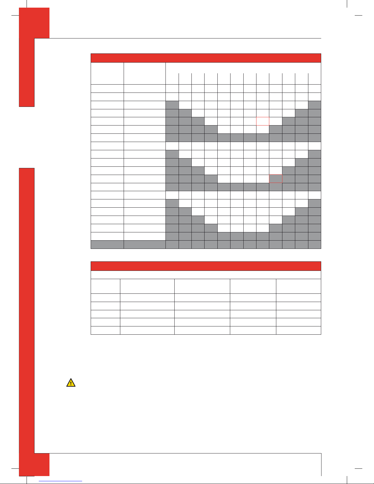
In the following procedure you can see how the allowability of a concentric system can be determined and which
settings are needed.
➠
Determine the following data:
1) The number of bends required (no distinction is made between 45° and 90° bends);
2) The total number of meters of horizontal pipe length;
3) The total number of meters of vertical and/or sloping pipe length (roof terminal excluded).
With these data and Table2 you will be able to determine whether the concentric system is allowed.
In Table3 you can see which setting the appliance requires.
Follow the procedure described below:
➠
In the rst 2 columns of Table2, look for the number of bends required and the total horizontal pipe length.
➠
In the 3rd column of Table2, look for the total vertical and/or sloping pipe length.
If you end up in a box with the letter A, B, C, D or E the concentric system chosen by you is allowed.
➠
Use Table3 to determine which conditions apply for the ba e, the air inlet guide and the injector screens (for setting,
see section 6.8).
Examples
To clarify, we will give 2 examples to determine the allowability of a concentric system and the conditions for setting
the appliance.
In Table 2 the route to be followed is indicated by arrows. The result is indicated by a box with a red border.
Example 1
1) 2 bends
2) 3 meters horizontal
3) 8 meters vertical/sloping
→ Construction of this concentric system is allowed.
→ Situation C applies for the adjustment of the appliance.
Example 2
1) 3 bends
2) 4 meters horizontal
3) 9 meters vertical/sloping
→ Construction of this concentric system is not allowed.
GB
95902801_GB Install.indd 995902801_GB Install.indd 9 12-7-10 11:2412-7-10 11:24
Page 10
10
MILO INSTALLATION MANUAL
English
Table 2: Determination of th e permissibility of a concentric system with a roof terminal
G20/G25/G31 Total number of
meters horizontal
pipe length
Total number of meters vertical and/or sloping pipe length
1234567
↓8 ↓9
10 11 12
no bends 0 B C C D D E E E E E E E
2 bends 0 A A B C C D D E E E E E
1 AABCCDDEEE
2AABCCDDE
→
3AABCCD
4AABC
5
3 bends 0 A A A B C C D D E E E E
1AAABCCDDEE
2AAABCCDD
3AAABCC
→
4AAAB
5
4 bends 0 A A A A B C C D D E E E
1 AAAABCCDDE
2AAAABCCD
3AAAABC
4AAAA
5
5 bends -
■
■ = situation is not allowed
Tabel 3: Voorwaarden voor afstellen van het toestel bij toepassing van een dakdoorvoer
G20/G25/G31
Situation Air inlet guide Injector screens* Ba e Distance of
restriction in mm
A N0 N0 N0 OPEN
B ADDITIONAL YES YES 30
C ADDITIONAL YES YES 24
D ADDITIONAL YES YES 19
E ADDITIONAL YES YES 15
■
■ = situation is not allowed
6.5.3.2 Placing concentric system with roof terminal
The roof terminal can end in a sloping and a at roof.
The roof terminal can be supplied with an adhesive plate for a at roof or with a universally adjustable tile for a sloping roof. In case of a sloping roof with a slope up to 24°, it is also necessary to use an adhesive plate.
Caution
- Maintain a distance of at least 50mm between the outside of the concentric system and the walls, when using a
round system;
- Maintain a distance of at least 23 mm between the outside of the concentric system and the walls, when using a
rectangular system; this distance is xed due to the construction of the rectangular system;
- Maintain a distance of at least 50mm between the outside of the concentric system and the ceiling;
- Use non combustible material for building the concentric in, for instance, a cove;
- Use heat-resistant insulation material when passing through combustible material.
!Caution
Some heat-resistant insulation materials contain volatile components that will spread an unpleasant smell for a
prolonged time; these are not suitable.
GB
95902801_GB Install.indd 1095902801_GB Install.indd 10 12-7-10 11:2412-7-10 11:24
Page 11
11
MILO INSTALLATION MANUAL
English
Place the concentric system as follows:
➠
Build the system up from (the ue spigot of ) the appliance.
➠
Connect the concentric pipe pieces, the adapter and, if necessary, the bends.
➠
In case of the rectangular system, you must rst attach a coupling piece on each connection, as described below
(see g.3d):
!Caution
In case of rectangular pipe pieces, the internal pipe is longer at the bottom than the external pipe; the internal pipe
glides in the internal pipe of the ue spigot or the previous pipe piece;
- For reducing a rectangular pipe piece, unscrew the internal pipe from the external pipe;
- Make the internal pipe and external pipe equally long at the top end;
- Retighten the internal pipe;
- Place the coupling piece plus seal on the reduced pipe piece and x it at both front sides by means of 2 self-drilling
screws.
- Place a red seal on the ue spigot of the appliance;
- Then, place the coupling piece on the ue spigot;
- Secure the coupling peace at both front sides using 2 self-tapping screws;
- Place a red seal on the coupling piece;
- Then place a rectangular pipe piece or an adapter to round;
- Secure the rectangular pipe piece or adapter at both front sides using 2 self-tapping screws;
- At each next rectangular pipe piece or at the adapter, place the spacer brackets on the pipe at the same height as the
coupling piece;
- Secure the spacer brackets to the wall, so that the weight of the pipes does not rest on the appliance.
➠
Attach the rst round concentric pipe piece to the adapter using 4 self-drilling screws.
➠
On this connection, apply a clip binding with silicon sealing ring.
In case of round pipe pieces, attach a clip binding with silicon sealing ring to each connection.
Use a self-tapping screw to x the clip binding to the pipe on locations that cannot be reached after installation.
In case of round pipes, apply su cient brackets, so that the weight of the pipes does not rest on the appliance.
➠
Determine the remaining length of the roof terminal.
➠
Make sure the roof terminal has the right dimensions.
!Caution
Make sure that the right insertion length is maintained.
➠
Connect the roof terminal to the concentric pipes.
!Caution
- Make sure that the universal tile ts well with the surrounding tiles;
➠
Make sure that t he adhesive plate ts well onto the at roof.
6.5.4 Connection of existing chimney
It is possible to connect the appliance to an existing channel.
A exible SS pipe is placed in the chimney for discharging ue gases. The surrounding space is used to supply combustion air.
Caution
Protect the gas control and pipes against dirt from the chimney.
The following requirements apply when connecting to an existing chimney:
- only possible after placement of a concentric adapter to round on the rectangular ue spigot;
!Caution
- Place a concentric adapter to round, using a coupling piece with accompanying seals;
- Secure the coupling piece by means of self-tapping screws;
- Attach the rst round concentric pipe piece to the adapter using 4 self-drilling screws;
- On this connection, apply a clip binding with silicon sealing ring.
- only allowed when used in combination with the special DRU chimney kit. The installation manual is also supplied;
- the dimensions should be at least 150 x 150 mm;
- the vertical length has a maximum of 12meters;
- the horizontal length has a maximum of 3meters;
- the existing chimney has to be clean;
- the existing chimney has to be tight.
GB
95902801_GB Install.indd 1195902801_GB Install.indd 11 12-7-10 11:2412-7-10 11:24
Page 12
12
MILO INSTALLATION MANUAL
English
If the appliance is installed into an existing chimney by means of a chimney kit, there may be a slight loss in heat
output.
For setting the appliance, the same conditions/instructions apply as for the concentric system described above.
6.6 Placing the chimney breast
The appliance was designed to suspend freely. The narrow chimney breast at the rear of the appliance is only intended to hide the ue gas discharge / combustion air supply system and the adjustable legs; see section 6.6.1.
Construction in a construction chimney breast is allowed. In this case, a mantel iron must be placed; DRU is able to
supply this; see section 6.6.2.
The chimney breast may only be made of plate material.
The thickness of the plate material may be 15mm minimum and 30mm maximum.
In order to reach a proper heat discharge, the chimney breast must be ventilated at both sides. At the bottom of the
chimney breast, an additional air supply must be made. DRU is able to supply di erent ventilation elements; the lux
no elements can be specially supplied for the narrow chimney breast.
Caution
- Use non combustible and heat-resistant materials for the chimney breast, including the top of the chimney breast,
the material in the chimney breast and the back wall of the chimney breast;
- The ventilation holes – which at both sides should be mounted as high as possible – should have a combined
passage of at least 200cm
2
.
- Make an air supply at the bottom of the chimney breast;
- Protect the gas control and pipes against cement and plaster.
!Caution
When placing the chimney breast, you should take the following into account: (see g.4a).
- the minimum width of the narrow chimney breast: 850mm;
- the location of the ventilation holes at both sides of the chimney breast;
- the location of the air supply at the bottom of the chimney breast;
- the measurements of the glass panes, so that they can be placed/removed after placing the chimney breast.
6.6.1 Placing the narrow chimney breast
Follow the procedure described below:
➠
Check whether the concentric system is placed correctly.
➠
Check at the rectangular system, whether the connections (coupling pieces) are installed with the accompanying seals
and self-tapping screws.
➠
In case of rectangular pipes, check the xture to the wall by means of screws, on locations that cannot be reached later.
➠
In case of round pipes, check the xture of the clip binding with self-tapping screws on places that cannot be reached
later on.
➠
Adjust the vertical adjustment strip to the thickness of the plate material; see g.1, arrow3.
➠
Attach the plate material.
Caution
Maintain a tolerance of approx. 2mm between plate material and construction frame; see g.4b.
➠
Apply the ventilation holes a t both sides of the chimney breast.
➠
Attach the air supply to the bottom of the chimney breast: min.45x550mm; see g.4a, arrow1.
➠
When using plaster nishing, the chimney breast should dry for at least 6 weeks before it is taken into operation,
in order to prevent cracks.
6.6.2 Placing the construction chimney breast
When using a construction chimney breast, a mantel iron must be placed, in order to avoid that the appliance is
burdened by the weight of the chimney breast.
!Caution
Make sure that the gas control and receiver, which are below the appliance, can still be reached.
Follow the procedure described below:
➠
Check whether the concentric system is placed correctly.
➠
Check at the rectangular system, whether the connections (coupling pieces) are installed with the accompanying seals
and self-tapping screws.
➠
In case of rectangular pipes, check the xture to the wall by means of screws, on locations that cannot be reached later.
➠
In case of round pipes, check the xture of the clip binding with self-tapping screws on places that cannot be reached
later on.
GB
95902801_GB Install.indd 1295902801_GB Install.indd 12 12-7-10 11:2412-7-10 11:24
Page 13
13
MILO INSTALLATION MANUAL
English
➠
Maintain su cient space around the appliance in the chimney breast, so the heat can escape:
- minimum internal height: ±1000mm.
➠
Cut the mantel iron to the correct size; see g.4c.
➠
Place the mantel iron.
➠
Use the nuts to connect the threaded rods to the corners of the mantel iron (1).
!Caution
Adjust the threaded rod in such a way with the tensioning nut (2) that you have su cient setting space.
➠
Determine the height of the eye (4).
➠
Connect the eye to the wall using the key bolt.
➠
Mount the hook (3) of the threaded rod to the eye.
➠
Make it all level by using the tensioning screw.
➠
Adjust the vertical adjustment strip to the thickness of the plate material; see g.1, arrow3.
➠
Attach the plate material.
➠
Apply the ventilation holes at both sides of the chimney breast.
➠
Attach the air supply to the bottom of the chimney breast: min.45x550mm.
➠
When using plaster nishing, the chimney breast should dry for at least 6 weeks before it is taken into operation,
in order to prevent cracks.
6.7 Connecting gas
Use the following procedure when connecting the gas; see also section 6.3, Gas connection:
!Caution
- The gas control is located under the appliance;
- Prevent twisting the gas tap when connecting the gas pipe.
➠
If necessary, blow clean the gas pipe.
➠
Connect the gas pipe with gas tap to the gas control.
➠
Bleed the gas pipe.
6.8 Adjusting the appliance
The appliance has to be set in such a way that it works correctly in combination with the applied concentric system.
For that purpose, a ba e is placed, the air inlet guide is removed or the additional air inlet guide is placed and the
injector screens are removed. The conditions for using a wall terminal are described in section 6.5.2.1, and for using
a roof terminal in section 6.5.3.1.
6.8.1 Ba e (R)
The ba e (R) is supplied separately; see g.5a.
This is mounted as follows (see g.5b):
➠
Place the ba e.
➠
Use the template supplied to set the distance of the restriction (see g.5c) as follows:
- A distance of 15 mm means that the ba e is closed to a maximum level;
- A distance of 19, 24 and 30 mm is set by means of the template.
➠
Fix the ba e by using the socket cap screw (U).
6.8.2 Air inlet guide
6.8.2.1 Removing the air inlet guide (L)
The air inlet guide (L) is xed to the back wall at the bottom of the appliance. You can see it if you look across the
burners.
If you want to remove it, proceed as follows; see g.6a:
➠
Unscrew the self-tapping screws (N) using the socket spanner supplied with the appliance and remove them.
➠
Remove the air inlet guide.
➠
Retighten the self-tapping screws.
6.8.2.2 Placing the additional air inlet guide
!Caution
Use the correct self-tapping screws (P) for placing the additional air inlet guide.
GB
95902801_GB Install.indd 1395902801_GB Install.indd 13 12-7-10 11:2412-7-10 11:24
Page 14
14
MILO INSTALLATION MANUAL
English
When placing, proceed as follows; see g.6b:
➠
Unscrew the self-tapping screws (P) using the socket spanner supplied with the appliance and remove them.
➠
Place the additional air inlet guide.
➠
Retighten the self-tapping screws (P).
6.8.3 Injector screens (T), not valid for G31
At the back of the burners, a at plate is mounted. The at plate is visible if you look onto the burners from above.
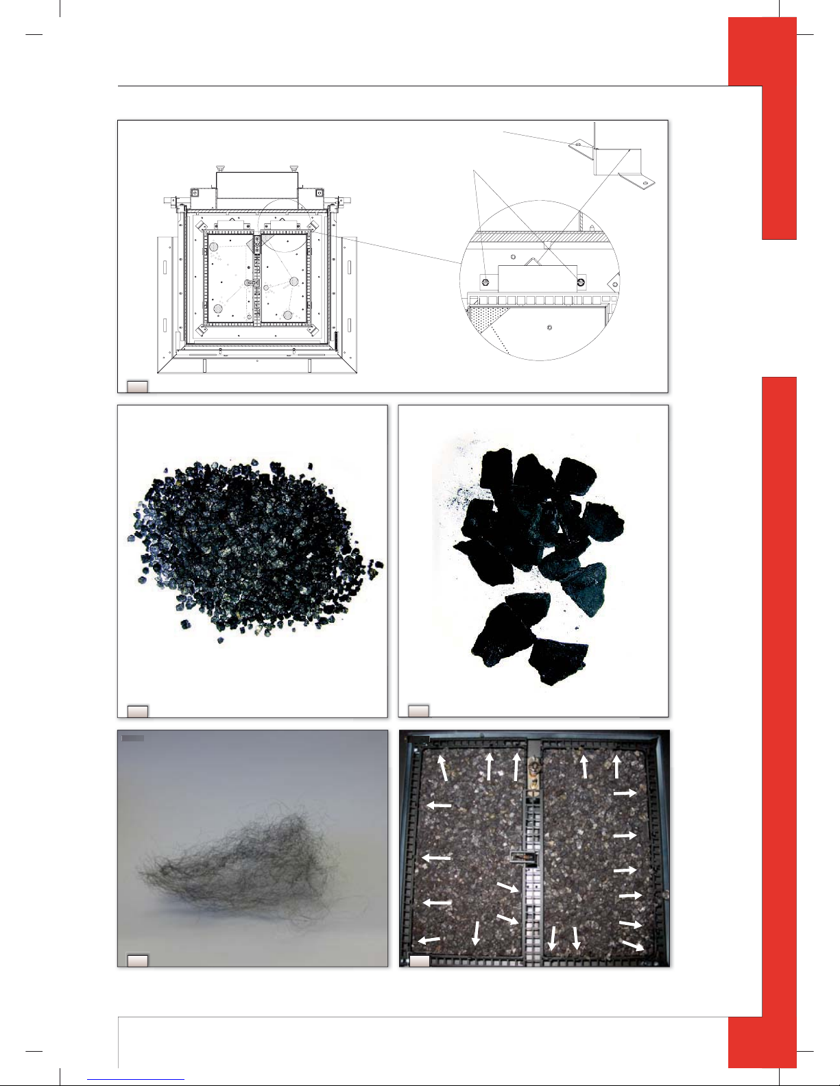
Below this, you will nd the injector screen which is connected to the burner mounting plate (bottom of the appliance) by means of 2 self-tapping screws; the heads of the 2 self-tapping screws can be seen from above.
When removing, proceed as follows; see g.6c:
➠
Unscrew the 2 self-tapping screws (S) using the socket spanner supplied with the appliance and remove them.
➠
Remove the injector screen.
➠
Retighten the self-tapping screws.
➠
Repeat these steps to remove the injector screen on the other burner.
6.9 Placing the wood set
The wood set consists of vermiculite (see g.7a), chips (see g.7b), glow wool (see g.8)and a number of logs.
Before placing the wood set, the inner frame (lacquered steel or four part set of natural stone) must be attached. The
inner frame is delivered with the base.
Caution
Strictly observe the following instructions to prevent unsafe situations:
- only use the inner frame supplied by DRU;
- only use the wood set supplied by DRU;
- place the wood set exactly as described;
- when placing the logs, use the ridges surrounding the burners; see g.9;
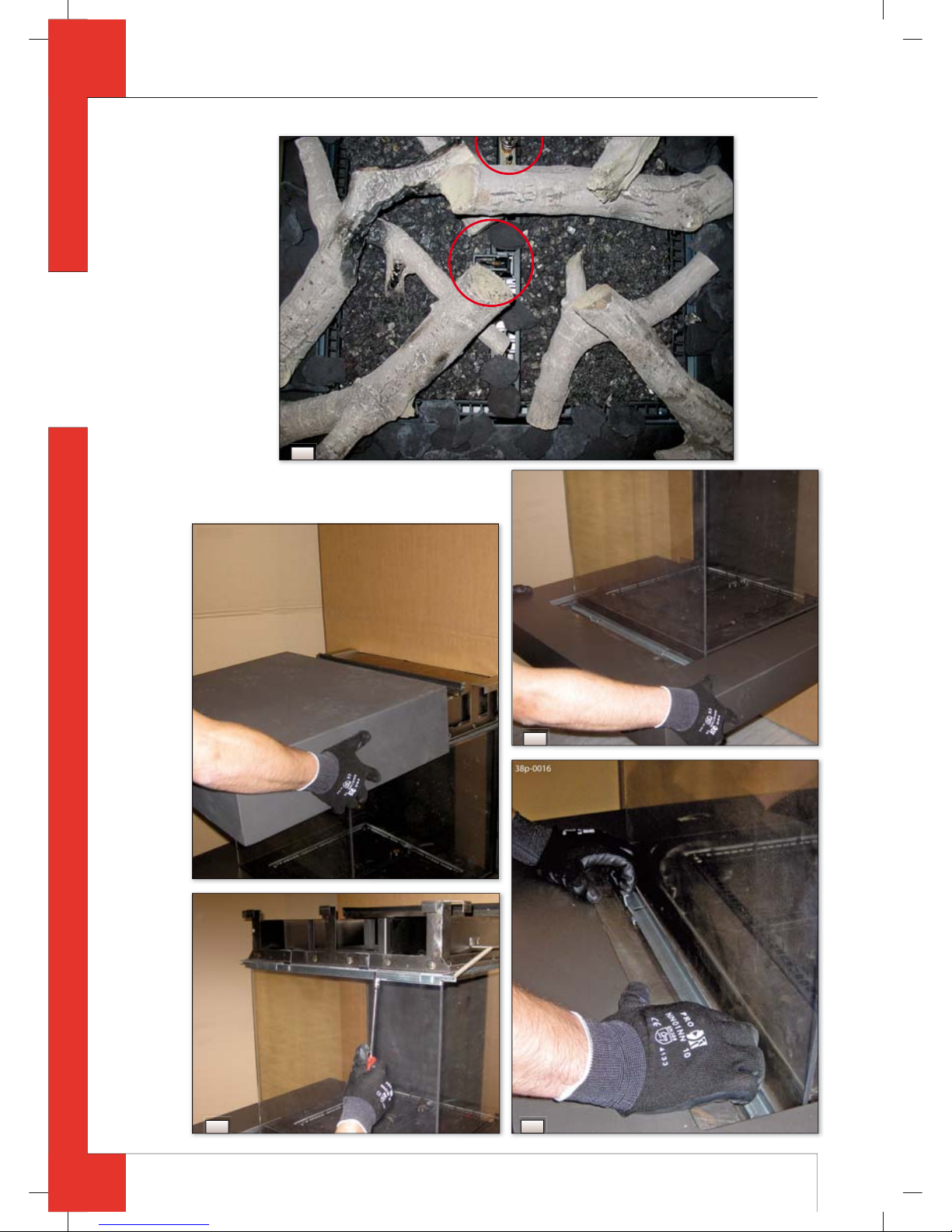
- make sure the pilot burner and the space around it are kept free from objects (see g.11f, circle);
- make sure that thermocouple2 and the space around it are kept free from objects (see g.11f, circle);
- make sure there is no vermiculite’s ne dust on the burners.
Follow the procedure described below:
➠
Place the lacquered steel frame on top of the four-piece set of natural stone; see g.10.
➠
Fill the burners with vermiculite; equally spread the vermiculite; see g.9.
!Caution
- You can in uence the ame image by moving the vermiculite, yet
- the burner deck has to remain covered with vermiculite in order to prevent that the life expectancy of the burners is
reduced.
➠
Identify logs A up to I by using g.11a.
!Tip
Use the burn stains on the logs for identi cation;
- The ridges that help you to place the logs are indicated by means of arrows.
➠
Place log A and log B (see g.11b).
➠
Then proceed with logs C, D and E (see g.11c):
- Place log C on the left burner;
- Place logs D and E on the right burner.
➠
Then place logs F and G on the left burner(see g.11d).
➠
Finally place logs H and I on the right burner (see g.11e).
Caution
- The logs may not fully cover the burner openings; the logs will be placed correctly if the ridges have been used;
- If necessary, improve the placement of the logs.
➠
Spread the glow wool evenly over the burners.
➠
Finally, place the chips around the logs; see g.11f.
Caution
Make sure that there are only a few chips on the grate surrounding the burners. The grate must remain largely free
for the aeration of the burners; this helps preventing that the ame picture is disturbed.
GB
95902801_GB Install.indd 1495902801_GB Install.indd 14 12-7-10 11:2412-7-10 11:24
Page 15

15
MILO INSTALLATION MANUAL
English
6.10 Glass panes
!Caution
- Avoid damaging the glass panes during removal/plac ing them;
- Avoid/remove ngerprints on the glass panes, as they will burn into the glass.
6.10.1 Front glass pane
After placing the wood set you can place the front glass pane as described below.
6.10.1.1 Removing the front glass pane
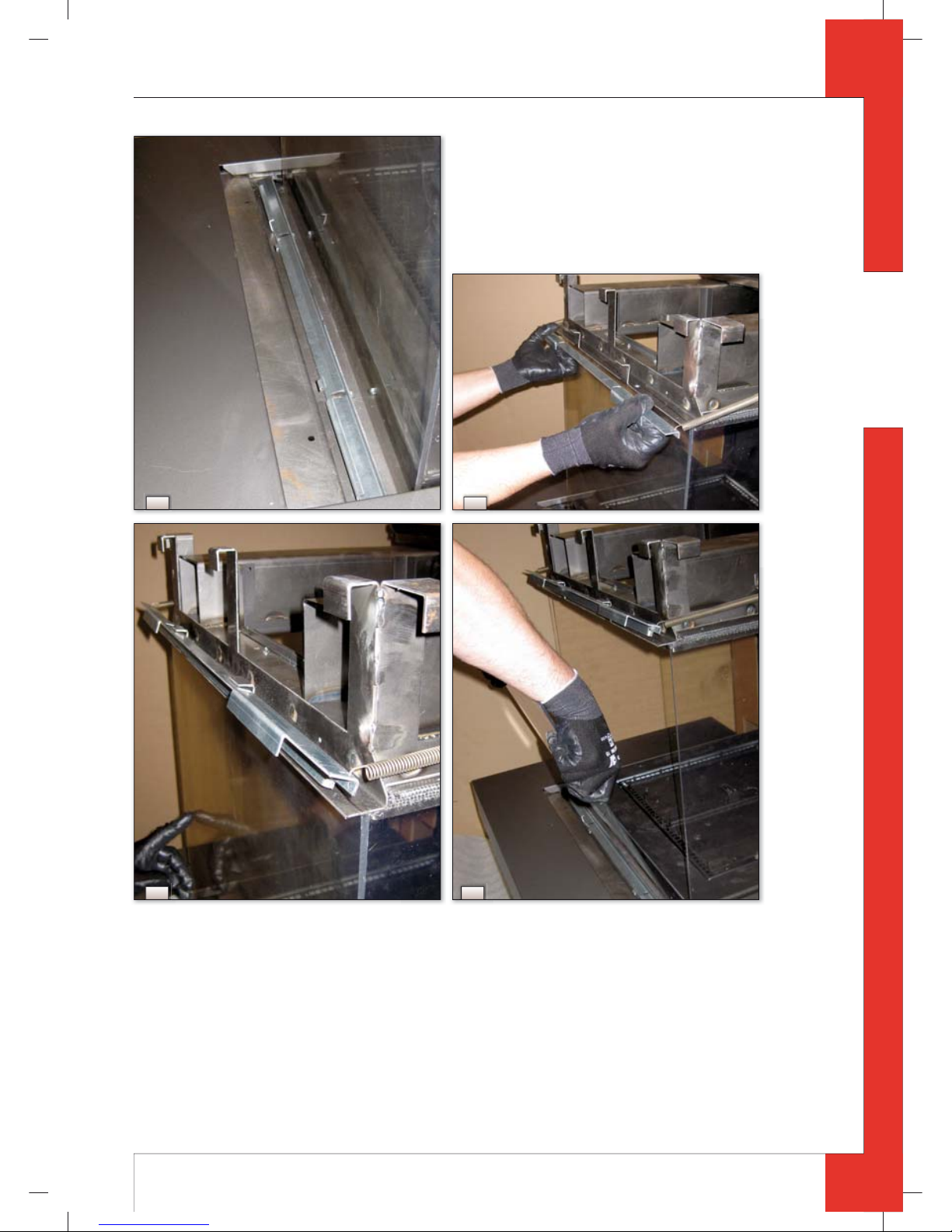
When removing the fron t glass pane, you should follow the next steps, see g.12a up to 12h:
➠
Remove the top on top of the appliance.
➠
Slide the base towards you.
➠
Unscrew the 2 self-tapping screws from the bottom and top springed glass strip, using the socket spanner supplied
with the appliance.
➠
Pull the lower springed glass strip upwards and towards you.
➠
Place the pins of the glass strips in the slots intended for that purpose.
!Caution
- Do not allow the springed glass strips to slip out, in order to avoid damaging/breaking the glass pane;
- Avoid that the glass pane falls out when loosening the top glass strip.
➠
Pull the top springed glass strip towards you and hold the glass pane at the same time.
➠
Place the top glass strip in the intended holder.
➠
Remove the glass pane.
➠
Store the glass pane on a safe place.
6.10.1.2 Placing the front glass pane
Placing the front glass pane will take place in reverse order of the removal procedure described above.
!Caution
- Do not allow the springed glass strips to slip out, in order to avoid damaging/breaking the glass pane;
- The DRU logo should be at the bottom right corner;
- The self-tapping screws must not be over-tightened, since otherwise they could break or strip the thread: tight=tight;
- Make sure that the front glass pane ts well onto the side glass panes.
6.10.2 Side glass panes
The side glass panes should be removed in case of torn or broken panes.
!Caution
The side glass panes can only be removed once the front glass pane has been removed.
6.10.2.1 Removing the side glass pane
Follow the procedure described below:
➠
Remove the front glass pane, see section 6.10.1.1. above.
➠
Remove the base by:
- sliding it towards you;
- removing the securing bolts; the bolts are at the bottom of the ends of the base;
- lifting the base.
➠
Store the base on a safe place.
!Caution
Natural stone is fragile; make sure that no pieces are broken o .
➠
Remove the vertical decorative strip by pushing the lip at the top of the strip, tilting the top of the strip parallel with
the glass pane, and then removing the strip.
➠
Unscrew the self-tapping screws from the upper glass strip, by using the socket spanner supplied.
➠
Remove the upper glass strip.
➠
Unscrew the self-tapping screws of the lower glass strip with 2 turns, using the socket spanner supplied.
➠
Unscrew the self-tapping screws of the vertical glass strip with 2 turns, using the socket spanner supplied.
!Caution
Do not remove the self-tapping screws: leave them in place in the lower and vertical glass strip.
➠
Remove the glass pane.
➠
Store the glass pane on a safe place.
GB
95902801_GB Install.indd 1595902801_GB Install.indd 15 12-7-10 11:2412-7-10 11:24
Page 16

16
MILO INSTALLATION MANUAL
English
6.10.2.2 Placing the side glass pane
Placing the side glass pane will take place in reverse order of the removal procedure described above.
!Caution
- Apply su cient pressure at the side of the glass pane, so it fully connects with the sealing;
- The self-tapping screws must not be over-tightened, since otherwise they could break or strip the thread: tight=tight.
6.11 Finishing the appliance
After placing the front glass pane, the base surrounding the appliance as well as the top of the appliance are placed.
When a construction chimney breast is used, the base and top are not placed.
The base is made of lacquered steel or natural stone.
During purchase of the appliance, a lacquered steel or natural stone base was selected.
The construction of the appliance was based on the weight of the DRU base.
!Caution
When using a heavier or larger base, an additional bearing construction must be placed, so that the appliance is not
burdened through the extension of the DRU base.
Follow the procedure described below:
➠
Place the base; see g.12b.
➠
Slide it away from you towards the wall.
➠
Attach the securing bolts, see g.13.
!Caution
Natural stone is fragile; make sure that no pieces are broken o .
➠
Place the top; see g.12a.
➠
Slide the top as far as possible to the back, against the chimney breast.
7. Wireless remote control
The appliance is supplied with a wireless remote control.
Ignition, controlling the ame height and switching o are perf ormed by a remote control that operates a receiver.
User Manual, chapter 4, Wireless Remote Control, describes the operation of the appliance including the way the
remote control works.
Caution
Do not ignite the appliance until it is fully installed.
Below, we will describe how the receiver is connected.
7.1 Recei ver
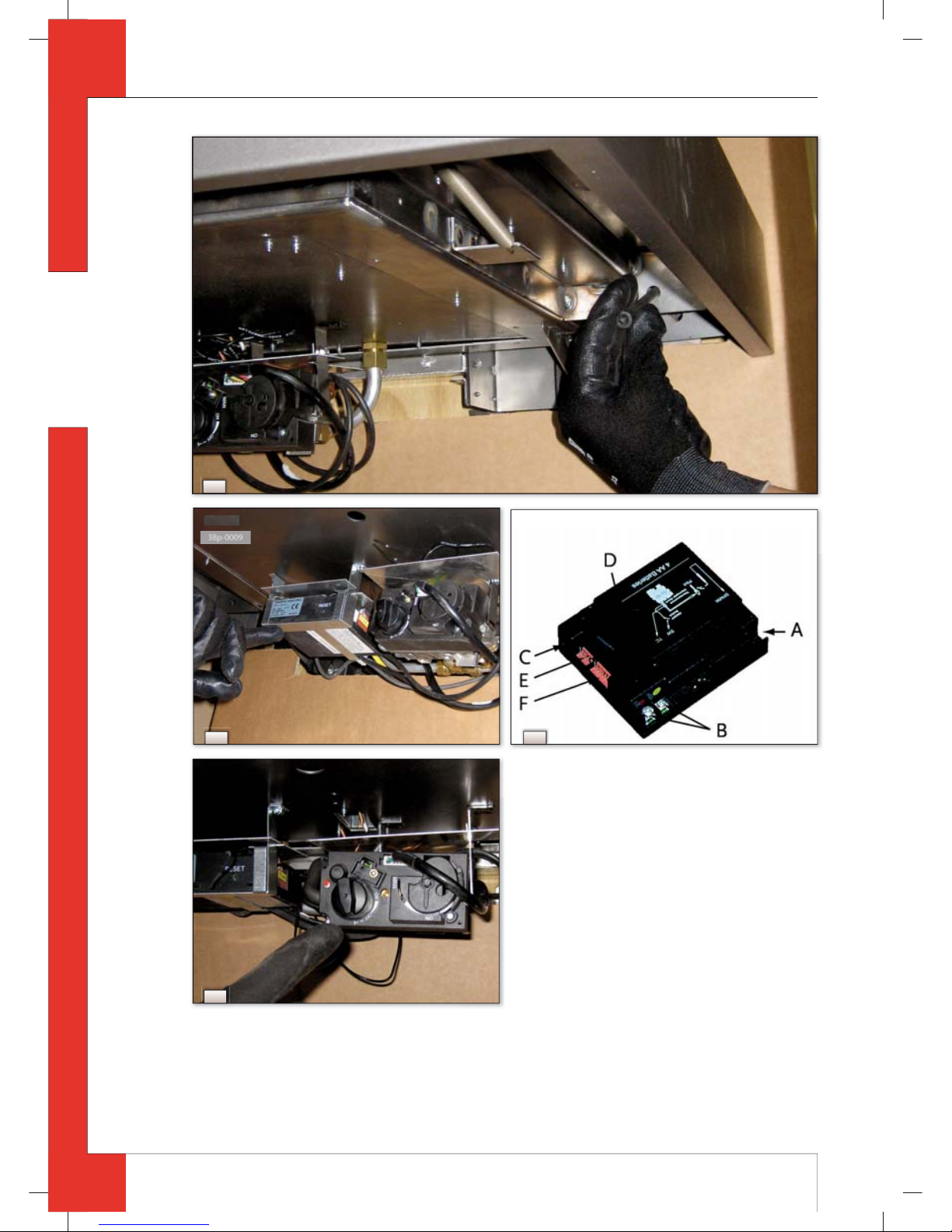
The receiver is placed in the holder under the appliance, after it was connected to the appliance; see g.14.
The gas control is mounted under the appliance (see g.16).
!Caution
- First connect the receiver to the appliance and then install the batteries;
- Make sure that the wiring of the receiver is free from the appliance.
In order to connect the receiver, you must proceed with the following steps (see g.15):
➠
Fit the connection cable’s brown plug to the receiver (see g.15,arrowF).
➠
Connect the white plug to the gas control.
!Tip
The plugs have di erent sizes that correspond with the connectors.
Connect the cables of thermocouple1 to the receiver; (see g.15, arrowsB).
!Tip
- The size of the eye corresponds with the size of the screw;
- The colours of eye and screw also correspond.
➠
Connect the black wire with the white plug of thermocouple 2 to the receiver (see g.15, arrowE).
!Caution
Make sure that the wires of thermocouple 2 cannot come into contact with hot parts
➠
Connect the ignition cable to the receiver; (see g.15, arrowA )
GB
95902801_GB Install.indd 1695902801_GB Install.indd 16 12-7-10 11:2412-7-10 11:24
Page 17

17
MILO INSTALLATION MANUAL
English
Connect power:
a) When using batteries, see section 7.1.1 below;
b) When using an adapter:
- connect it to the receiver; (see g.15, arrowC);
- insert the plug into the wall socket.
➠
Place the receiver (V), as indicated on g.14 and g.17.
➠
Bend the antenna out of the clips; see g.15, arrowD.
➠
Set the antenna straight.
!Caution
- Do not place the antenna (N) too close to the ignition cable and/or metal parts (for the correct position, see g.17);
- Do not place the ignition cable over and/or along metal parts: this will weaken the spark;
- Do not lay the ignition cable over the receiver: this could damage the receiver;
- Avoid dust on or in the recei ver: cover it when performing work.
7.1.1 Placing / replacing the batteries
Follow the procedure below when placing the batteries:
➠
Open the door of the control box.
➠
Pick up the receiver.
➠
Slide the cover o .
➠
Place or remove the 4 penlite (AA type) batteries.
!Caution
- Avoid a short circuit between the batteries and metal objects/parts;
- Observe the “+” and “-” poles of the batteries and the holder;
- Use alkaline batteries.
➠
Slide back the cover.
➠
Place back the receiver.
!Caution
Batteries are regarde d as “small chemical waste” and may therefore not be disposed with the household rubbish.
8. Final check
In order to check whether the appliance is working properly and safely, you must perform the following checks
before the appliance is used.
8.1 Gastightness
Caution
All connections must be gastight.
!Caution
The gas control can be subjected to a maximum pressure of 50 mbar.
➠
Check the connections for gastightness.
8.2 Gas pressure / line-pressure
The burner pressure is set at the factory; see data plate. It is not necessary to check the burner pressure.
Caution
The line-pressure in house installations should be checked, as they can vary.
➠
Check the line-pressure; see Appendix2/Table7 when propane is used and g.18 for the measuring nipple on the
gas control.
➠
Contact the gas company if the line-pressure is not correct.
8.3 Ignition pilot burner and main burners
For igniting the pilot burner and main burners, see the User Manual, chapter 4, section 4.2, Remote Control.
Caution
- During the ignition process, you are not allowed to operate control button B on the gas control manually;
- Always wait 5 minutes after the pilot burner has gone out, before you re-ignite the appliance.
- Do not turn the pilot burner lower by using the settings on the gas control.
GB
95902801_GB Install.indd 1795902801_GB Install.indd 17 12-7-10 11:2412-7-10 11:24
Page 18
18
MILO INSTALLATION MANUAL
English
8.3.1 Pilot burner
➠
Check the ign ition of the pilot burner:
- the pilot burner should start at the rst attempt.
If the pilot burner does not ignite:
➠
check if the ignition sparks:
a) If not, the ignition cable is probably not lying free from metal parts;
b) If it does, there is probably still air in the pipe.
➠
Bleed the pipe and/or
➠
Lay the ignition cable free from metal parts.
8.3.2 Main burners
Caution
The burners should ignite smoothly and should not pop as a result of delayed ignition.
➠
Check the function of the main burners from the standby (pilot burner) position:
- after opening the gas valve, the main burners should burn within a few seconds.
!Tip
When the gas valve is opened, the motor will run; this is audible.
1) If the main burners do not burn:
➠
Check if button A on the gas control is in the position ON;
➠
Check if the space surrounding the pilot burner is free from objects;
➠
Check the placement of the wood set.
➠
If necessary, correct the above mentioned faults.
➠
Test the main burners 5x for a good operation.
2) If the main burners ignite, but go out again after approx. 22 seconds, please:
➠
Check the wiring of thermocouple 2 for:
- Loose wiring;
- Wrongly connected wiring;
- Short-circuit;
- Broken wire.
➠
Check if thermocouple 2 is dirty.
➠
Check if thermocouple2 is positioned correctly in the ame; see g.19.
➠
Check if thermocouple 2 is defective; see chapter 11, table 4 under J7.
➠
Check if the receiver is defective; see chapter 11, table 4 under J8.
➠
If necessary, correct the above mentioned faults.
➠
Test the main burners 5x for a good operation.
8.4 Flame image
The ame image can only really be assessed when the appliance has been burning for several hours. Volatile components from paint, materials, etc., which evaporate in the rst hours, will a ect the ame image.
!Caution
If the chimney breast is made of stone-like materials or has a plaster nish, this may only take place 6 weeks after
placing the chimney breast, in order to prevent shrinkage cracks.
➠
Check whether the ame image is acceptable.
If the ame image is not acceptable, this can be due to:
- the evaporation of volatile substances;
- incorrect placement of the wood set;
- incorrect settings of the appliance.
➠
If necessary, improve the placement of the wood set.
➠
If necessary, improve the settings of the appliance; for this, see section 6.8.
9. Maintenance
Once a year the appliance should be checked, cleaned and, if necessary, repaired by a competent installer in the eld
of atmospheric gas- red heating.
Check at least whether the appliance is working properly and safely.
GB
95902801_GB Install.indd 1895902801_GB Install.indd 18 12-7-10 11:2412-7-10 11:24
Page 19

19
MILO INSTALLATION MANUAL
English
Caution
- Close the gas tap when performing maintenance work;
- Check the gastightness after repair;
- After replacing thermocouple1 you should rst tighten the swivel by hand and then give it another quarter turn
with a suitable spanner;
- Do not turn the pilot burner lower by using the settings on the gas control.
➠
If required, clean the following components:
- the pilot burner;
- the space surrounding the pilot burner;
- the glass panes.
!Caution
- Remove/place the glass panes as described in section 6.10;
- Remove the deposit on the inside of the glass panes with a damp cloth or a non-abrasive detergent such as copper
polish;
- Avoid/remove ngerprints on the glass panes, as they will burn into the glass;
- Replace a broken and/or cracked glass pane as described in section 6.10.
Caution
If necessary, place back the wood set correctly; for this, see section 6.9.
➠
Inspect the ue gas discharge / combustion air supply system.
Caution
You must always perform a nal check.
➠
Perform a check as described in chapter 8.
9.1 Parts
Parts that must be replaced, can be obtained from your supplier.
10. Delivery
You must explain to the user how he should operate the appliance. You should instruct her/him for instance on using the appliance for the rst time, the operation of the remote control, annual maintenance.
Caution
- Tell the user to close the gas tap immediately in case of malfunctions/bad performance and contact the installer in
order to prevent dangerous situations;
- Indicate the location of the gas tap;
- Point out the location of the receiver and the gas control;
- Point out the precautions in the user manual concerning unintended ignition by other remote controls such as car
keys and garage door openers.
➠
Instruct the user about the appliance and the remote control.
➠
When the appliance is started for the rst time, point out that
- in order to avoid cracks in a chimney breast nished with plaster, it should dry for at least 6 weeks prior to putting
the appliance into operation
- when the appliance is stoked up for the rst time, volatile components evaporate from paint, materials, etc.;
- when evaporating, the appliance should preferably be set at the highest level;
- the room should be well ventilated.
➠
Give the user manual and installation manual to the user (the installation manual should be kept near the appliance).
11. Malfunctions
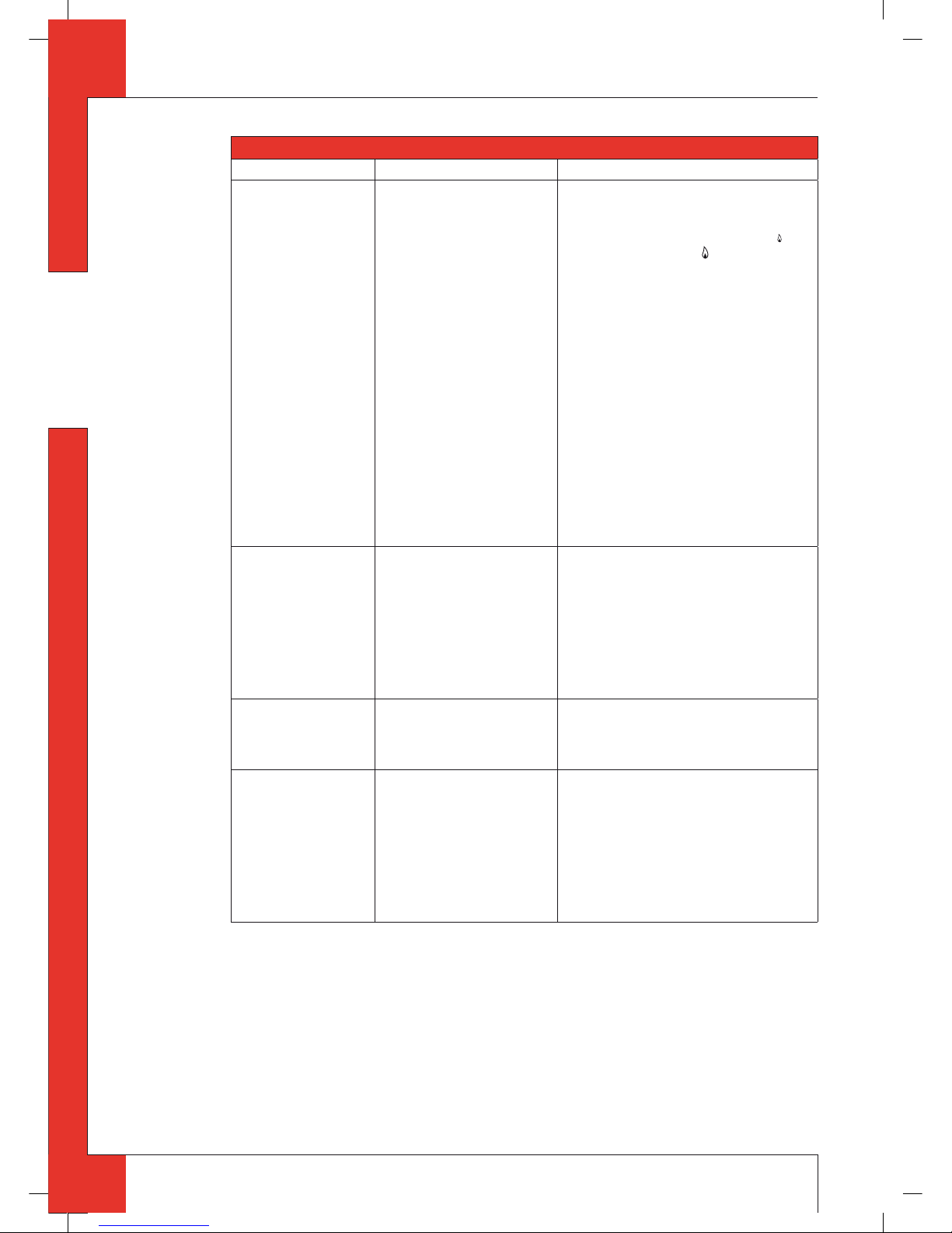
In the following table you will nd an overview of malfunctions that might occur, the possible causes and the
remedies.
GB
95902801_GB Install.indd 1995902801_GB Install.indd 19 12-7-10 11:2412-7-10 11:24
Page 20
20
MILO INSTALLATION MANUAL
English
Table 4: Diagnosis of malfunctions
Problem Possible cause Remedy
A. No transmission
(motor will not run)
1. The (new) communication
code between receiver and
remote control must still be
con rmed.
2. Empty batteries.
3. Receiver is damaged.
4. Remote control is damaged.
5. Motor cable at valve/receiver is
broken.
6. Bent pins of the 8-wire connector.
7. If the receiver is surrounded by
metal, this could decrease the
transmission range.
1. Hold down the reset button of the receiver,
until you hear 2 sound signals; see g.20.
Let go of the reset button after the second,
longer sound signal and press button
(small ame) or button
(large ame) on the
remote control within 20sec., until you hear
an extra long sound signal con rming that
the new code has been set.
2. Replace batteries.
!Caution
Avoid short circuit between the batteries
and metal parts of the appliance.
3. Replace the receiver and con rm the code
(remedy 1).
4. Replace the remote control and con rm the
code (remedy 1).
5. Replace the motor cable.
6. Make sure that the pins of the 8-wire connector are straight.
7. Change the position of the antenna.
B. No ignition (spark) 1. Button A in position MAN.
2. Ignition cable runs over and/or
alongside metal parts.
3. Ignition pen corroded.
4. 60-second delay before the full
restart is not yet nished.
1. Switch button A on the gas control to ON, see
g 16.
2 Do not place the ignition cable over and/or
along metal parts. This will weaken the spark;
see g.17.
If necessary, replace the ignition cable.
3. Replace the ignition pen.
4. Wait until the delay time has passed.
C. No sound signal 1. Receiver is damaged.
2. 60-second delay before the full
restart is not yet nished.
1. Replace the receiver and con rm the code
(remedy 1 at A)
2. Wait until the delay time has passed.
D. One continuous sound
signal of 5 sec.
(Possible 7 short beeps
prior to the 5 sec.
sound signal)
1. Loose wiring between receiver
and gas control.
2. Receiver is damaged.
3. Bent pins of the 8-wire connector.
4. Damaged magnetic valve.
5. Thermocouple 2 still too hot.
1. Connect the wiring properly.
2. Replace the receiver and con rm the code
(remedy 1 at A)
3. Make sure that the pins of the 8-wire connector are straight.
4. Replace the gas control.
5. Wait until the thermocouple has cooled down
su ciently
GB
95902801_GB Install.indd 2095902801_GB Install.indd 20 12-7-10 11:2412-7-10 11:24
Page 21

21
MILO INSTALLATION MANUAL
English
Table 4: Diagnosis of malfunctions
Problem Possible cause Remedy
E. No pilot burner ame 1. Air in the pilot burner pipe.
2. Wires of thermocouple 1 have
been cross-connected.
3. No spark at the pilot burner.
4. Injector is blocked up.
1. Flush the pipe or start the ignition process
several times.
2. Check the polarity of the thermocouple wiring.
Connect the thermocouple wiring properly, if
necessary.
3.1 Check if the ignition cable is lying free from
metal parts; see g.17.
If necessary, move it away from the metal
parts.
3.2 If necessary, replace the ignition cable.
3.3 If necessary, replace the ignition pen.
4.1 Clean the injector.
4.2 If necessary, replace the injector.
F. Electronics keep spar-
king while the pilot
burner is ignited
1. Receiver is damaged. 1. Replace the receiver and con rm the code
(remedy 1 at A)
G. Pilot burner is burning,
but magnetic valve closes after ca. 10 seconds
or when the appliance
gets hot
1. Thermocouple 1 does not
function.
2. Batteries (almost) empty.
1.1 Measure the voltage, using a digital multimeter, set to mV range, by connecting the cables
to the cable shoe. The cable shoe is located on
the outside, directly next to the magnet nut at
the rear of the gas control; see g.21.
The voltage should be at least 5mV within 20
seconds.
It may not be lower when the appliance is
warm.
If the voltage is too low:
- the thermocouple should be placed better in
the ame or
- the thermocouple should be replaced.
1.2 Check the size of the pilot burner ame.
Correct a ame that is too small.
1.3 Check the wiring of the thermocouple to the
receiver.
If necessary, replace the wiring.
2. Replace the receiver’s batteries.
!Caution
Avoid short circuit between the batteries
and metal parts of the appliance.
H. There are short sound
signals, but no sparks
and no sound / clicks
can be heard of the
magnet opening the
valve
1. Batteries (almost) empty. 1. Replace the receiver’s batteries.
!Caution
Avoid short circuit between the batteries
and metal parts of the appliance.
I. Pilot burner is burning,
but there is no gas ow
to the main burner
1. Button A in position MAN.
2. Appliance in the pilot ame
position.
3. Line-pressure of the gas is too
low.
4. Damaged magnetic valve.
1. Turn button A on the gas control to ON; see
g 16.
2. Increase the ame height by pressing button
(large ame) on the remote control.
3. Check line-pressure.
If necessary, contact gas company.
4. Replace the gas control.
GB
95902801_GB Install.indd 2195902801_GB Install.indd 21 12-7-10 11:2512-7-10 11:25
Page 22

22
MILO INSTALLATION MANUAL
English
Table 4: Diagnosis of malfunctions
Problem Possible cause Remedy
J. Main burner ignites,
but goes out again after approx. 22 seconds.
1. Wiring of thermocouple 2 is
loose.
2. Wires of thermocouple 2 have
been cross-connected.
3. Short-circuit in the wiring of
thermocouple 2.
4. Broken wire in the wiring of
thermocouple 2.
5. Thermocouple 2 is dirty.
6. Thermocouple 2 is not positioned correctly in the ame
(see g. 19)
7. Thermocouple 2 is defective.
8. Receiver is defective.
1. Connect the wiring properly.
2. Connect the wiring properly.
3. Replace wiring.
4. Replace wiring.
5. Clean the thermocouple.
6. Position the thermocouple correctly in the
ame.
7. Check the voltage across thermocouple 2 just
before the main burners go out.
If the voltage is lower than 1.8 mV, replace
thermocouple 2.
8. Check the voltage across thermocouple 2 just
before the main burners go out.
If the voltage is higher than 1.8 mV, replace
the receiver.
Appendix 1 Parts included with t he delivery
In the following table you can nd the parts that are supplied with the appliance.
Table 5: Parts included with the del ivery
Part Quantity
Wood sets 1x
Installation manual 1x
User manual 1x
Decorative strip left 1x
Decorative strip right 1x
Inner frame; lacquered steel or a four part set of natural stone 1x
Base; lacquered steel or natural stone 1x
Securing bolts for base 2x
Top 1x
Template for ba e 1x
Ba e 1x
Additional air inlet guide ( at plate) 1x
Wall bracket 1x
Key bolts M8x 140x50 4x
Hexagonal nut M8 4x
Washer 8.4 mm 4x
Spare self-tapping screws for mounting the glass panes
Socket spanner 8 mm 1x
Remote control with receiver 1x
9V block battery 1x
Penlite battery (AA type) 4x
GB
95902801_GB Install.indd 2295902801_GB Install.indd 22 12-7-10 11:2512-7-10 11:25
Page 23

23
MILO INSTALLATION MANUAL
English
Appendix 2 Technical data
In the following tables you can nd the technical data of the Milo.
Table 6: Technical data
Type C11/C31
Type of gas G25 G20 G31
Burner pressure mbar 18.9 15.1 27.2
Nominal heat input (H
s
) kW 10.2 11.3 10.5
Nominal heat input (H
i
) kW 9.2 10.2 9.7
Nominal output kW 7.0 7.7 7.5
Consumption L/h 1086 1050 402
Burner injector mm 2x Ø 1.8 2x Ø 1.8 2x Ø 1.2
Consumption on low output L/h 641 611 235
Low setting injector mm Ø 1.90 Ø 1.90 Ø 1.4
Pilot burner injector Kode 51 51 30
E ciency class 2 2 2
Tabel 7: Line-pressure when using G31
Country
mbar
NL / DK / FI / NO / SE / HU / BA / GR
30
FR / BE / IT / PT / ES / GB / IE 37
DE
50
GB
95902801_GB Install.indd 2395902801_GB Install.indd 23 12-7-10 11:2512-7-10 11:25
Page 24
24
MILO INSTALLATION MANUAL
English
Appendix 3 Figures
1
GB
95902801_GB Install.indd 2495902801_GB Install.indd 24 12-7-10 11:2512-7-10 11:25
Page 25

25
MILO INSTALLATION MANUAL
English
3b
3c
C
38c-1424
C
A
B
3a
2
A
B
38c-1425
GB
95902801_GB Install.indd 2595902801_GB Install.indd 25 12-7-10 11:2512-7-10 11:25
Page 26

26
MILO INSTALLATION MANUAL
English
770
mm
702
mm
621
mm
550
mm
75
mm
Min. 850
mm
180
mm
230 mm
45
mm
Min. 220
Min.
200 cm²
1
38c-1420
4a
38c-1428
3d
GB
95902801_GB Install.indd 2695902801_GB Install.indd 26 12-7-10 11:2512-7-10 11:25
Page 27
27
MILO INSTALLATION MANUAL
English
4
2
3
1
230
180
38c-1421
AA
B
B
A-A
2
mm
B-B
2
mm
38c-1432
4b
4c
GB
95902801_GB Install.indd 2795902801_GB Install.indd 27 12-7-10 11:2512-7-10 11:25
Page 28

28
MILO INSTALLATION MANUAL
English
P
38c-1429
6b
L
N
38c-1427
6a
38c-1426
R
U
5b
U
R
38c-1422
5a
30
24
19
38c-1423
5c
GB
95902801_GB Install.indd 2895902801_GB Install.indd 28 12-7-10 11:2512-7-10 11:25
Page 29
29
MILO INSTALLATION MANUAL
English
8
38p-0028
9
38p-0001
38p-0023
7b
S
T
38c-1430
38c-1430
6c
38p-0022
7a
GB
95902801_GB Install.indd 2995902801_GB Install.indd 29 12-7-10 11:2512-7-10 11:25
Page 30

30
MILO INSTALLATION MANUAL
English
A
B
38p-0002
11b
A
BC
DE
F
G
H
I
38p-0007
11a
10
GB
95902801_GB Install.indd 3095902801_GB Install.indd 30 12-7-10 11:2612-7-10 11:26
Page 31

31
MILO INSTALLATION MANUAL
English
C
D
E
38p-0003
11c
H
I
38p-ooo5
11e
F
G
38P-0004
11d
GB
95902801_GB Install.indd 3195902801_GB Install.indd 31 12-7-10 11:2612-7-10 11:26
Page 32
32
MILO INSTALLATION MANUAL
English
12d
38p-0015
12c
12a
38P-0014
12b
38p-0021
38p-0006
11f
GB
95902801_GB Install.indd 3295902801_GB Install.indd 32 12-7-10 11:2612-7-10 11:26
Page 33
33
MILO INSTALLATION MANUAL
English
38p-0018
12f
38p-0017
12e
38p-0019
12g
38p-0020
12h
GB
95902801_GB Install.indd 3395902801_GB Install.indd 33 12-7-10 11:2612-7-10 11:26
Page 34
34
MILO INSTALLATION MANUAL
English
38p-0011
16
14
38p-0025
15
38p-0010
13
GB
95902801_GB Install.indd 3495902801_GB Install.indd 34 12-7-10 11:2612-7-10 11:26
Page 35

35
MILO INSTALLATION MANUAL
English
38p-0024
18
38p-0012
17
33
mm
17
mm
38c-1433
19
38p-0026
20
38p-0027
21
GB
95902801_GB Install.indd 3595902801_GB Install.indd 35 12-7-10 11:2712-7-10 11:27
Page 36
36
MILO INSTALLATION MANUAL
English
Appendix 4 Figures
760
580
540
680
1340
795 300
155
400
150
50
185
230
160
480
950
275 / 390
400
400
220
220
155
593
155
593
GRP24
215
500
160
D 430
38a
GB
95902801_GB Install.indd 3695902801_GB Install.indd 36 12-7-10 11:2712-7-10 11:27
Page 37

37
MILO INSTALLATION MANUAL
English
1360
535 580
110
220
110
80
115
110
220
110
105
80
220
80
110
110
160
228
340
90
280
38
110
Verwarming
38C-1444
38b
GB
95902801_GB Install.indd 3795902801_GB Install.indd 37 12-7-10 11:2712-7-10 11:27
Page 38

38
MILO INSTALLATION MANUAL
English
995
206
200
38C-1445
38c
GB
95902801_GB Install.indd 3895902801_GB Install.indd 38 12-7-10 11:2712-7-10 11:27
Page 39

39
MILO INSTALLATION MANUAL
English
Notes
. . . . . . . . . . . . . . . . . . . . . . . . . . . . . . . . . . . . . . . . . . . . . . . . . . . . . . . . . . . . . . . . . . . . . . . . . . . . . . . . . . . . . . . . . . . . . . . . . . . . . . . . . . . . . . . . . . . . . . . . . . . . . . . . . . . . . . . . . . . . . . . . . . . . . . . . . . . . . . . . . . . . . . . . . . . . . . . . . . . . . . . . . . . . . . . . . . . . . . . . . . . . . . . . . . . . . . . . . . . . . . . . . . . . . . . . . . . . . . . . . . . . . . . . . . . . .
. . . . . . . . . . . . . . . . . . . . . . . . . . . . . . . . . . . . . . . . . . . . . . . . . . . . . . . . . . . . . . . . . . . . . . . . . . . . . . . . . . . . . . . . . . . . . . . . . . . . . . . . . . . . . . . . . . . . . . . . . . . . . . . . . . . . . . . . . . . . . . . . . . . . . . . . . . . . . . . . . . . . . . . . . . . . . . . . . . . . . . . . . . . . . . . . . . . . . . . . . . . . . . . . . . . . . . . . . . . . . . . . . . . . . . . . . . . . . . . . . . . . . . . . . . . . .
. . . . . . . . . . . . . . . . . . . . . . . . . . . . . . . . . . . . . . . . . . . . . . . . . . . . . . . . . . . . . . . . . . . . . . . . . . . . . . . . . . . . . . . . . . . . . . . . . . . . . . . . . . . . . . . . . . . . . . . . . . . . . . . . . . . . . . . . . . . . . . . . . . . . . . . . . . . . . . . . . . . . . . . . . . . . . . . . . . . . . . . . . . . . . . . . . . . . . . . . . . . . . . . . . . . . . . . . . . . . . . . . . . . . . . . . . . . . . . . . . . . . . . . . . . . . .
. . . . . . . . . . . . . . . . . . . . . . . . . . . . . . . . . . . . . . . . . . . . . . . . . . . . . . . . . . . . . . . . . . . . . . . . . . . . . . . . . . . . . . . . . . . . . . . . . . . . . . . . . . . . . . . . . . . . . . . . . . . . . . . . . . . . . . . . . . . . . . . . . . . . . . . . . . . . . . . . . . . . . . . . . . . . . . . . . . . . . . . . . . . . . . . . . . . . . . . . . . . . . . . . . . . . . . . . . . . . . . . . . . . . . . . . . . . . . . . . . . . . . . . . . . . . .
. . . . . . . . . . . . . . . . . . . . . . . . . . . . . . . . . . . . . . . . . . . . . . . . . . . . . . . . . . . . . . . . . . . . . . . . . . . . . . . . . . . . . . . . . . . . . . . . . . . . . . . . . . . . . . . . . . . . . . . . . . . . . . . . . . . . . . . . . . . . . . . . . . . . . . . . . . . . . . . . . . . . . . . . . . . . . . . . . . . . . . . . . . . . . . . . . . . . . . . . . . . . . . . . . . . . . . . . . . . . . . . . . . . . . . . . . . . . . . . . . . . . . . . . . . . . .
. . . . . . . . . . . . . . . . . . . . . . . . . . . . . . . . . . . . . . . . . . . . . . . . . . . . . . . . . . . . . . . . . . . . . . . . . . . . . . . . . . . . . . . . . . . . . . . . . . . . . . . . . . . . . . . . . . . . . . . . . . . . . . . . . . . . . . . . . . . . . . . . . . . . . . . . . . . . . . . . . . . . . . . . . . . . . . . . . . . . . . . . . . . . . . . . . . . . . . . . . . . . . . . . . . . . . . . . . . . . . . . . . . . . . . . . . . . . . . . . . . . . . . . . . . . . .
. . . . . . . . . . . . . . . . . . . . . . . . . . . . . . . . . . . . . . . . . . . . . . . . . . . . . . . . . . . . . . . . . . . . . . . . . . . . . . . . . . . . . . . . . . . . . . . . . . . . . . . . . . . . . . . . . . . . . . . . . . . . . . . . . . . . . . . . . . . . . . . . . . . . . . . . . . . . . . . . . . . . . . . . . . . . . . . . . . . . . . . . . . . . . . . . . . . . . . . . . . . . . . . . . . . . . . . . . . . . . . . . . . . . . . . . . . . . . . . . . . . . . . . . . . . . .
. . . . . . . . . . . . . . . . . . . . . . . . . . . . . . . . . . . . . . . . . . . . . . . . . . . . . . . . . . . . . . . . . . . . . . . . . . . . . . . . . . . . . . . . . . . . . . . . . . . . . . . . . . . . . . . . . . . . . . . . . . . . . . . . . . . . . . . . . . . . . . . . . . . . . . . . . . . . . . . . . . . . . . . . . . . . . . . . . . . . . . . . . . . . . . . . . . . . . . . . . . . . . . . . . . . . . . . . . . . . . . . . . . . . . . . . . . . . . . . . . . . . . . . . . . . . .
. . . . . . . . . . . . . . . . . . . . . . . . . . . . . . . . . . . . . . . . . . . . . . . . . . . . . . . . . . . . . . . . . . . . . . . . . . . . . . . . . . . . . . . . . . . . . . . . . . . . . . . . . . . . . . . . . . . . . . . . . . . . . . . . . . . . . . . . . . . . . . . . . . . . . . . . . . . . . . . . . . . . . . . . . . . . . . . . . . . . . . . . . . . . . . . . . . . . . . . . . . . . . . . . . . . . . . . . . . . . . . . . . . . . . . . . . . . . . . . . . . . . . . . . . . . . .
. . . . . . . . . . . . . . . . . . . . . . . . . . . . . . . . . . . . . . . . . . . . . . . . . . . . . . . . . . . . . . . . . . . . . . . . . . . . . . . . . . . . . . . . . . . . . . . . . . . . . . . . . . . . . . . . . . . . . . . . . . . . . . . . . . . . . . . . . . . . . . . . . . . . . . . . . . . . . . . . . . . . . . . . . . . . . . . . . . . . . . . . . . . . . . . . . . . . . . . . . . . . . . . . . . . . . . . . . . . . . . . . . . . . . . . . . . . . . . . . . . . . . . . . . . . . .
. . . . . . . . . . . . . . . . . . . . . . . . . . . . . . . . . . . . . . . . . . . . . . . . . . . . . . . . . . . . . . . . . . . . . . . . . . . . . . . . . . . . . . . . . . . . . . . . . . . . . . . . . . . . . . . . . . . . . . . . . . . . . . . . . . . . . . . . . . . . . . . . . . . . . . . . . . . . . . . . . . . . . . . . . . . . . . . . . . . . . . . . . . . . . . . . . . . . . . . . . . . . . . . . . . . . . . . . . . . . . . . . . . . . . . . . . . . . . . . . . . . . . . . . . . . . .
. . . . . . . . . . . . . . . . . . . . . . . . . . . . . . . . . . . . . . . . . . . . . . . . . . . . . . . . . . . . . . . . . . . . . . . . . . . . . . . . . . . . . . . . . . . . . . . . . . . . . . . . . . . . . . . . . . . . . . . . . . . . . . . . . . . . . . . . . . . . . . . . . . . . . . . . . . . . . . . . . . . . . . . . . . . . . . . . . . . . . . . . . . . . . . . . . . . . . . . . . . . . . . . . . . . . . . . . . . . . . . . . . . . . . . . . . . . . . . . . . . . . . . . . . . . . .
. . . . . . . . . . . . . . . . . . . . . . . . . . . . . . . . . . . . . . . . . . . . . . . . . . . . . . . . . . . . . . . . . . . . . . . . . . . . . . . . . . . . . . . . . . . . . . . . . . . . . . . . . . . . . . . . . . . . . . . . . . . . . . . . . . . . . . . . . . . . . . . . . . . . . . . . . . . . . . . . . . . . . . . . . . . . . . . . . . . . . . . . . . . . . . . . . . . . . . . . . . . . . . . . . . . . . . . . . . . . . . . . . . . . . . . . . . . . . . . . . . . . . . . . . . . . .
. . . . . . . . . . . . . . . . . . . . . . . . . . . . . . . . . . . . . . . . . . . . . . . . . . . . . . . . . . . . . . . . . . . . . . . . . . . . . . . . . . . . . . . . . . . . . . . . . . . . . . . . . . . . . . . . . . . . . . . . . . . . . . . . . . . . . . . . . . . . . . . . . . . . . . . . . . . . . . . . . . . . . . . . . . . . . . . . . . . . . . . . . . . . . . . . . . . . . . . . . . . . . . . . . . . . . . . . . . . . . . . . . . . . . . . . . . . . . . . . . . . . . . . . . . . . .
. . . . . . . . . . . . . . . . . . . . . . . . . . . . . . . . . . . . . . . . . . . . . . . . . . . . . . . . . . . . . . . . . . . . . . . . . . . . . . . . . . . . . . . . . . . . . . . . . . . . . . . . . . . . . . . . . . . . . . . . . . . . . . . . . . . . . . . . . . . . . . . . . . . . . . . . . . . . . . . . . . . . . . . . . . . . . . . . . . . . . . . . . . . . . . . . . . . . . . . . . . . . . . . . . . . . . . . . . . . . . . . . . . . . . . . . . . . . . . . . . . . . . . . . . . . . .
. . . . . . . . . . . . . . . . . . . . . . . . . . . . . . . . . . . . . . . . . . . . . . . . . . . . . . . . . . . . . . . . . . . . . . . . . . . . . . . . . . . . . . . . . . . . . . . . . . . . . . . . . . . . . . . . . . . . . . . . . . . . . . . . . . . . . . . . . . . . . . . . . . . . . . . . . . . . . . . . . . . . . . . . . . . . . . . . . . . . . . . . . . . . . . . . . . . . . . . . . . . . . . . . . . . . . . . . . . . . . . . . . . . . . . . . . . . . . . . . . . . . . . . . . . . . .
. . . . . . . . . . . . . . . . . . . . . . . . . . . . . . . . . . . . . . . . . . . . . . . . . . . . . . . . . . . . . . . . . . . . . . . . . . . . . . . . . . . . . . . . . . . . . . . . . . . . . . . . . . . . . . . . . . . . . . . . . . . . . . . . . . . . . . . . . . . . . . . . . . . . . . . . . . . . . . . . . . . . . . . . . . . . . . . . . . . . . . . . . . . . . . . . . . . . . . . . . . . . . . . . . . . . . . . . . . . . . . . . . . . . . . . . . . . . . . . . . . . . . . . . . . . . .
. . . . . . . . . . . . . . . . . . . . . . . . . . . . . . . . . . . . . . . . . . . . . . . . . . . . . . . . . . . . . . . . . . . . . . . . . . . . . . . . . . . . . . . . . . . . . . . . . . . . . . . . . . . . . . . . . . . . . . . . . . . . . . . . . . . . . . . . . . . . . . . . . . . . . . . . . . . . . . . . . . . . . . . . . . . . . . . . . . . . . . . . . . . . . . . . . . . . . . . . . . . . . . . . . . . . . . . . . . . . . . . . . . . . . . . . . . . . . . . . . . . . . . . . . . . . .
. . . . . . . . . . . . . . . . . . . . . . . . . . . . . . . . . . . . . . . . . . . . . . . . . . . . . . . . . . . . . . . . . . . . . . . . . . . . . . . . . . . . . . . . . . . . . . . . . . . . . . . . . . . . . . . . . . . . . . . . . . . . . . . . . . . . . . . . . . . . . . . . . . . . . . . . . . . . . . . . . . . . . . . . . . . . . . . . . . . . . . . . . . . . . . . . . . . . . . . . . . . . . . . . . . . . . . . . . . . . . . . . . . . . . . . . . . . . . . . . . . . . . . . . . . . . .
. . . . . . . . . . . . . . . . . . . . . . . . . . . . . . . . . . . . . . . . . . . . . . . . . . . . . . . . . . . . . . . . . . . . . . . . . . . . . . . . . . . . . . . . . . . . . . . . . . . . . . . . . . . . . . . . . . . . . . . . . . . . . . . . . . . . . . . . . . . . . . . . . . . . . . . . . . . . . . . . . . . . . . . . . . . . . . . . . . . . . . . . . . . . . . . . . . . . . . . . . . . . . . . . . . . . . . . . . . . . . . . . . . . . . . . . . . . . . . . . . . . . . . . . . . . . .
. . . . . . . . . . . . . . . . . . . . . . . . . . . . . . . . . . . . . . . . . . . . . . . . . . . . . . . . . . . . . . . . . . . . . . . . . . . . . . . . . . . . . . . . . . . . . . . . . . . . . . . . . . . . . . . . . . . . . . . . . . . . . . . . . . . . . . . . . . . . . . . . . . . . . . . . . . . . . . . . . . . . . . . . . . . . . . . . . . . . . . . . . . . . . . . . . . . . . . . . . . . . . . . . . . . . . . . . . . . . . . . . . . . . . . . . . . . . . . . . . . . . . . . . . . . . .
. . . . . . . . . . . . . . . . . . . . . . . . . . . . . . . . . . . . . . . . . . . . . . . . . . . . . . . . . . . . . . . . . . . . . . . . . . . . . . . . . . . . . . . . . . . . . . . . . . . . . . . . . . . . . . . . . . . . . . . . . . . . . . . . . . . . . . . . . . . . . . . . . . . . . . . . . . . . . . . . . . . . . . . . . . . . . . . . . . . . . . . . . . . . . . . . . . . . . . . . . . . . . . . . . . . . . . . . . . . . . . . . . . . . . . . . . . . . . . . . . . . . . . . . . . . . .
. . . . . . . . . . . . . . . . . . . . . . . . . . . . . . . . . . . . . . . . . . . . . . . . . . . . . . . . . . . . . . . . . . . . . . . . . . . . . . . . . . . . . . . . . . . . . . . . . . . . . . . . . . . . . . . . . . . . . . . . . . . . . . . . . . . . . . . . . . . . . . . . . . . . . . . . . . . . . . . . . . . . . . . . . . . . . . . . . . . . . . . . . . . . . . . . . . . . . . . . . . . . . . . . . . . . . . . . . . . . . . . . . . . . . . . . . . . . . . . . . . . . . . . . . . . . .
. . . . . . . . . . . . . . . . . . . . . . . . . . . . . . . . . . . . . . . . . . . . . . . . . . . . . . . . . . . . . . . . . . . . . . . . . . . . . . . . . . . . . . . . . . . . . . . . . . . . . . . . . . . . . . . . . . . . . . . . . . . . . . . . . . . . . . . . . . . . . . . . . . . . . . . . . . . . . . . . . . . . . . . . . . . . . . . . . . . . . . . . . . . . . . . . . . . . . . . . . . . . . . . . . . . . . . . . . . . . . . . . . . . . . . . . . . . . . . . . . . . . . . . . . . . . .
. . . . . . . . . . . . . . . . . . . . . . . . . . . . . . . . . . . . . . . . . . . . . . . . . . . . . . . . . . . . . . . . . . . . . . . . . . . . . . . . . . . . . . . . . . . . . . . . . . . . . . . . . . . . . . . . . . . . . . . . . . . . . . . . . . . . . . . . . . . . . . . . . . . . . . . . . . . . . . . . . . . . . . . . . . . . . . . . . . . . . . . . . . . . . . . . . . . . . . . . . . . . . . . . . . . . . . . . . . . . . . . . . . . . . . . . . . . . . . . . . . . . . . . . . . . . .
. . . . . . . . . . . . . . . . . . . . . . . . . . . . . . . . . . . . . . . . . . . . . . . . . . . . . . . . . . . . . . . . . . . . . . . . . . . . . . . . . . . . . . . . . . . . . . . . . . . . . . . . . . . . . . . . . . . . . . . . . . . . . . . . . . . . . . . . . . . . . . . . . . . . . . . . . . . . . . . . . . . . . . . . . . . . . . . . . . . . . . . . . . . . . . . . . . . . . . . . . . . . . . . . . . . . . . . . . . . . . . . . . . . . . . . . . . . . . . . . . . . . . . . . . . . . .
. . . . . . . . . . . . . . . . . . . . . . . . . . . . . . . . . . . . . . . . . . . . . . . . . . . . . . . . . . . . . . . . . . . . . . . . . . . . . . . . . . . . . . . . . . . . . . . . . . . . . . . . . . . . . . . . . . . . . . . . . . . . . . . . . . . . . . . . . . . . . . . . . . . . . . . . . . . . . . . . . . . . . . . . . . . . . . . . . . . . . . . . . . . . . . . . . . . . . . . . . . . . . . . . . . . . . . . . . . . . . . . . . . . . . . . . . . . . . . . . . . . . . . . . . . . . .
. . . . . . . . . . . . . . . . . . . . . . . . . . . . . . . . . . . . . . . . . . . . . . . . . . . . . . . . . . . . . . . . . . . . . . . . . . . . . . . . . . . . . . . . . . . . . . . . . . . . . . . . . . . . . . . . . . . . . . . . . . . . . . . . . . . . . . . . . . . . . . . . . . . . . . . . . . . . . . . . . . . . . . . . . . . . . . . . . . . . . . . . . . . . . . . . . . . . . . . . . . . . . . . . . . . . . . . . . . . . . . . . . . . . . . . . . . . . . . . . . . . . . . . . . . . . .
. . . . . . . . . . . . . . . . . . . . . . . . . . . . . . . . . . . . . . . . . . . . . . . . . . . . . . . . . . . . . . . . . . . . . . . . . . . . . . . . . . . . . . . . . . . . . . . . . . . . . . . . . . . . . . . . . . . . . . . . . . . . . . . . . . . . . . . . . . . . . . . . . . . . . . . . . . . . . . . . . . . . . . . . . . . . . . . . . . . . . . . . . . . . . . . . . . . . . . . . . . . . . . . . . . . . . . . . . . . . . . . . . . . . . . . . . . . . . . . . . . . . . . . . . . . . .
. . . . . . . . . . . . . . . . . . . . . . . . . . . . . . . . . . . . . . . . . . . . . . . . . . . . . . . . . . . . . . . . . . . . . . . . . . . . . . . . . . . . . . . . . . . . . . . . . . . . . . . . . . . . . . . . . . . . . . . . . . . . . . . . . . . . . . . . . . . . . . . . . . . . . . . . . . . . . . . . . . . . . . . . . . . . . . . . . . . . . . . . . . . . . . . . . . . . . . . . . . . . . . . . . . . . . . . . . . . . . . . . . . . . . . . . . . . . . . . . . . . . . . . . . . . . .
. . . . . . . . . . . . . . . . . . . . . . . . . . . . . . . . . . . . . . . . . . . . . . . . . . . . . . . . . . . . . . . . . . . . . . . . . . . . . . . . . . . . . . . . . . . . . . . . . . . . . . . . . . . . . . . . . . . . . . . . . . . . . . . . . . . . . . . . . . . . . . . . . . . . . . . . . . . . . . . . . . . . . . . . . . . . . . . . . . . . . . . . . . . . . . . . . . . . . . . . . . . . . . . . . . . . . . . . . . . . . . . . . . . . . . . . . . . . . . . . . . . . . . . . . . . . .
. . . . . . . . . . . . . . . . . . . . . . . . . . . . . . . . . . . . . . . . . . . . . . . . . . . . . . . . . . . . . . . . . . . . . . . . . . . . . . . . . . . . . . . . . . . . . . . . . . . . . . . . . . . . . . . . . . . . . . . . . . . . . . . . . . . . . . . . . . . . . . . . . . . . . . . . . . . . . . . . . . . . . . . . . . . . . . . . . . . . . . . . . . . . . . . . . . . . . . . . . . . . . . . . . . . . . . . . . . . . . . . . . . . . . . . . . . . . . . . . . . . . . . . . . . . . .
. . . . . . . . . . . . . . . . . . . . . . . . . . . . . . . . . . . . . . . . . . . . . . . . . . . . . . . . . . . . . . . . . . . . . . . . . . . . . . . . . . . . . . . . . . . . . . . . . . . . . . . . . . . . . . . . . . . . . . . . . . . . . . . . . . . . . . . . . . . . . . . . . . . . . . . . . . . . . . . . . . . . . . . . . . . . . . . . . . . . . . . . . . . . . . . . . . . . . . . . . . . . . . . . . . . . . . . . . . . . . . . . . . . . . . . . . . . . . . . . . . . . . . . . . . . . .
. . . . . . . . . . . . . . . . . . . . . . . . . . . . . . . . . . . . . . . . . . . . . . . . . . . . . . . . . . . . . . . . . . . . . . . . . . . . . . . . . . . . . . . . . . . . . . . . . . . . . . . . . . . . . . . . . . . . . . . . . . . . . . . . . . . . . . . . . . . . . . . . . . . . . . . . . . . . . . . . . . . . . . . . . . . . . . . . . . . . . . . . . . . . . . . . . . . . . . . . . . . . . . . . . . . . . . . . . . . . . . . . . . . . . . . . . . . . . . . . . . . . . . . . . . . . .
. . . . . . . . . . . . . . . . . . . . . . . . . . . . . . . . . . . . . . . . . . . . . . . . . . . . . . . . . . . . . . . . . . . . . . . . . . . . . . . . . . . . . . . . . . . . . . . . . . . . . . . . . . . . . . . . . . . . . . . . . . . . . . . . . . . . . . . . . . . . . . . . . . . . . . . . . . . . . . . . . . . . . . . . . . . . . . . . . . . . . . . . . . . . . . . . . . . . . . . . . . . . . . . . . . . . . . . . . . . . . . . . . . . . . . . . . . . . . . . . . . . . . . . . . . . . .
. . . . . . . . . . . . . . . . . . . . . . . . . . . . . . . . . . . . . . . . . . . . . . . . . . . . . . . . . . . . . . . . . . . . . . . . . . . . . . . . . . . . . . . . . . . . . . . . . . . . . . . . . . . . . . . . . . . . . . . . . . . . . . . . . . . . . . . . . . . . . . . . . . . . . . . . . . . . . . . . . . . . . . . . . . . . . . . . . . . . . . . . . . . . . . . . . . . . . . . . . . . . . . . . . . . . . . . . . . . . . . . . . . . . . . . . . . . . . . . . . . . . . . . . . . . . .
. . . . . . . . . . . . . . . . . . . . . . . . . . . . . . . . . . . . . . . . . . . . . . . . . . . . . . . . . . . . . . . . . . . . . . . . . . . . . . . . . . . . . . . . . . . . . . . . . . . . . . . . . . . . . . . . . . . . . . . . . . . . . . . . . . . . . . . . . . . . . . . . . . . . . . . . . . . . . . . . . . . . . . . . . . . . . . . . . . . . . . . . . . . . . . . . . . . . . . . . . . . . . . . . . . . . . . . . . . . . . . . . . . . . . . . . . . . . . . . . . . . . . . . . . . . . .
. . . . . . . . . . . . . . . . . . . . . . . . . . . . . . . . . . . . . . . . . . . . . . . . . . . . . . . . . . . . . . . . . . . . . . . . . . . . . . . . . . . . . . . . . . . . . . . . . . . . . . . . . . . . . . . . . . . . . . . . . . . . . . . . . . . . . . . . . . . . . . . . . . . . . . . . . . . . . . . . . . . . . . . . . . . . . . . . . . . . . . . . . . . . . . . . . . . . . . . . . . . . . . . . . . . . . . . . . . . . . . . . . . . . . . . . . . . . . . . . . . . . . . . . . . . . .
. . . . . . . . . . . . . . . . . . . . . . . . . . . . . . . . . . . . . . . . . . . . . . . . . . . . . . . . . . . . . . . . . . . . . . . . . . . . . . . . . . . . . . . . . . . . . . . . . . . . . . . . . . . . . . . . . . . . . . . . . . . . . . . . . . . . . . . . . . . . . . . . . . . . . . . . . . . . . . . . . . . . . . . . . . . . . . . . . . . . . . . . . . . . . . . . . . . . . . . . . . . . . . . . . . . . . . . . . . . . . . . . . . . . . . . . . . . . . . . . . . . . . . . . . . . . .
GB
95902801_GB Install.indd 3995902801_GB Install.indd 39 12-7-10 11:2712-7-10 11:27
Page 40

MILO INSTALLATION MANUAL
English
DRU Verwarming B.V.
The Netherlands
Postbus 1021, NL-6920 BA Duiven
Ratio 8, NL-6921 RW Duiven
GB
95902801_GB Install.indd 4095902801_GB Install.indd 40 12-7-10 11:2712-7-10 11:27
 Loading...