

Page 1
English
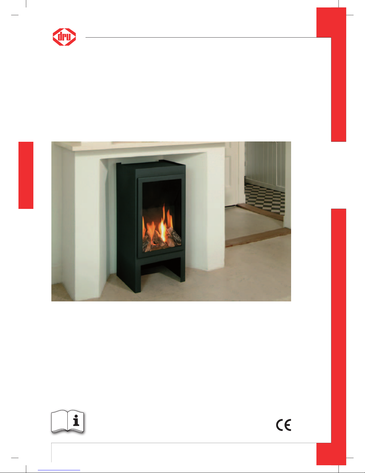
Solo
G20/G25
Please retain this document carefully
Instructions for installation (GB / IE)
UK
95900605 UK Install_G20.indd 195900605 UK Install_G20.indd 1 2-2-10 12:552-2-10 12:55
Page 2
2
English
SOLO - INSTRUCTION FOR INSTALLATION
Contents
page
Preface 2
1. Introduction 3
2. CE declaration 3
3. SAFETY 3
3.1 General 3
3.2 Regulations 3
3.3 Precautions / safety instructions during installation 3
4. Instructions 4
5. Removing the packaging 4
6. Installation 4
6.1 Regulations 4
6.2 Type of gas 4
6.3 Gas connection 4
6.4 Reconstructing from top connection appliance to back connection appliance 4
6.5 Placing the appliance 5
6.6 Flue gas discharge / combustion air supply system 5
6.7 Connecting gas 10
6.8 Adjusting the appliance 10
6.9 Placing wood set 11
6.10 Pane 11
7. Operation 14
7.1 Wireless remote control 14
8. Final check 15
8.1 Gastightness 15
8.2 Gas pressure / pre-pressure 15
8.3 Ignition pilot and main burner 15
8.4 Flame image 15
9. Maintenance 16
10. Delivery 16
11. Malfunctions 17
Appendix 1 Parts included with the delivery 18
Appendix 2 Technical data 18
Appendix 3 Parts 18
Preface
DRU, a manufacturer of gas heating appliances, develops and produces products that comply with the highest quality, performance and safety requirements.
This guarantees that the user will be able to enjoy using his product for many years to come.
This appliance has a CE marking, which means that it complies with the essential requirements of the European gas
appliance directive.
As an installer, you must be competent in the fi eld of atmospheric gas heating.
Two manuals are supplied with the appliance: the instructions for installation and the operating instructions.
The instructions for installation will provide you with the information you need to install the appliance in such a way
that it will operate properly and safely.
This manual discusses the installation of the appliance and the regulations that apply to the installation. In addition,
you will fi nd technical data for the appliance and information on maintenance, any malfunctions that might occur
and their possible causes.
Please carefully read and use these instructions for installation.
The following symbols are used in the manual to indicate important information:
➠
Work to be performed
!Tip
Suggestions and recommendations
!Caution
You will need these instructions to prevent problems that might occur during installation and/or use.
Caution
You need these instructions to prevent re, personal injury or other serious damages.
After delivery, you should give the operating instructions and the instructions for installation to the user.
UK
95900605 UK Install_G20.indd 295900605 UK Install_G20.indd 2 2-2-10 12:552-2-10 12:55
Page 3
3
English
SOLO - INSTRUCTION FOR INSTALLATION
1. Introduction
Solo is a freestanding atmospheric gas heating appliance.
This version of Solo is suitable for natural gas.
Solo is a closed appliance. A closed appliance does not extract the combustion air from the living environment, but
from outside. This is done through a combined fl ue gas discharge system / combustion air supply system. In this
concentric system the outer pipe serves as air supply and the inner pipe as fl ue gas discharge.
This system can be installed through the wall, or through the roof.
The concentric system can be supplied in the colour of the appliance.
The appliance is supplied with a battery powered wireless remote control.
2. CE declaration
The undersigned, representative of :
Manufacturer: DRU Haardkachels B.V.
Postbus 37, NL-6660 AA Elst
Industrieweg Oost 11, NL-6662 NE Elst
hereby declares that the design and construction of DRU’ atmospheric gas heating appliance comply with the essential requirements of the Gas Appliance Directive.
Product: atmospheric gas heating appliance
Type: Solo
Applicable EEC directives: 90/396/EEC
Applied harmonized standards: NEN-EN-613
NEN-EN-613/A1
Internal measures by the company guarantee that appliances produced in series comply with the essential requirements of the prevailing EEC directives and the standards derived from them.
This declaration will lose its validity if adjustments are made to the appliance, without prior written permission by
DRU.
On behalf of DRU Haardkachels B.V.
M.J.M Gelten
General director
Postbus 1021, 6920 BA Duiven
Ratio 8, 6921 RW Duiven
3. SAFETY
3.1 General
Caution
- Carefully read this chapter on safety, before you start performing installation or maintenance work;
- Please observe the general regulations and the precautions/safety instructions in this manual.
3.2 Regulations
Please install the appliance in accordance with the applicable national, local and constructional (installation) regulations.
In the Netherlands the “Bouwbesluit” applies, amongst other regulations.
3.3 Precautions / safety instructions during installation
Carefully observe the following precautions/safety regulations:
➠
you should only install and maintain the appliance if you are a competent installer in the eld of atmospheric gas heating;
➠
do not make any changes to the appliance;
➠
only use the ue gas discharge / combustion air supply system supplied by DRU;
➠
place the appliance at a distance of at least 50 mm from the back wall;
➠
do not cover the appliance and the discharge material and/or do not wrap them in an insulation blanket or any other
material;
➠
always place the appliance and/or the discharge pipes at a minimum distance of 500 mm from combustible objects or
materials;
➠
only ever use the supplied wood set;
➠
place the wood set exactly as described;
➠
make sure the pilot burner and the space around it are kept free;
UK
95900605 UK Install_G20.indd 395900605 UK Install_G20.indd 3 2-2-10 12:552-2-10 12:55
Page 4
4
English
SOLO - INSTRUCTION FOR INSTALLATION
➠
avoid dirt in gas pipes and connections;
➠
check the connections for gastightness before using the appliance;
➠
do not ignite the appliance until it is fully installed;
➠
replace torn or broken panes.
4. Instructions
Observe the following items during installation in order to guarantee a proper and safe operation of the appliance:
➠
avoid that the ignition cable runs over and/or alongside metal parts, in order to prevent weakening of the spark;
➠
avoid damaging the pane during removal/placing;
➠
clean the pane before you use the appliance, in order to prevent dirt from burning in the glass.
5. Removing the packaging
Note the following items when removing the packaging:
➠
Check the appliance for damages during transport.
➠
If necessary, contact your dealer.
After removing the pane, you can take the box containing parts and the wood set from the combustion room.
!Caution
Avoid damaging the pane during removal/placing.
➠
Remove the pane as described in section 6.10.1;
➠
Remove the box containing parts and the wood set from the combustion room.
In Appendix 1 / Table 4 you can see which parts you should have after removing the packaging.
➠
Contact your dealer if you do not have all the parts after you nished removing the packaging;
➠
Dispose packaging in accordance with local regulations.
6. Installation
Read this manual carefully to ensure a proper and safe operation of the appliance.
!Caution
Install the appliance in the order described in this chapter.
6.1 Regulations
- Observe the applicable (installation) regulations.
- Observe the regulations/instructions in this manual.
6.2 Type of gas
The type plate indicates for which type of gas, gas pressure and for which country this appliance is intended. The type
plate can be found at the left side on the back wall of the space at the bottom of the appliance.
➠
Check whether the appliance is suitable for the type of gas and the gas pressure used on site.
!Caution
By default, the appliance is set up for gas type G25. If you connect the appliance to gas type G20, you should change
the primary aeration. For more details, see Table 2 and section 6.8.2
6.3 Gas connection
Place a gas tap in the gas connection, close to the appliance.
Caution
Avoid dirt in the gas pipe and in the connections.
The following requirements apply to the gas connection:
- use a gas pipe with the correct dimensions, so that no pressure loss can occur:
- the gas tap should have the CE marking;
- you should always be able to reach the gas tap.
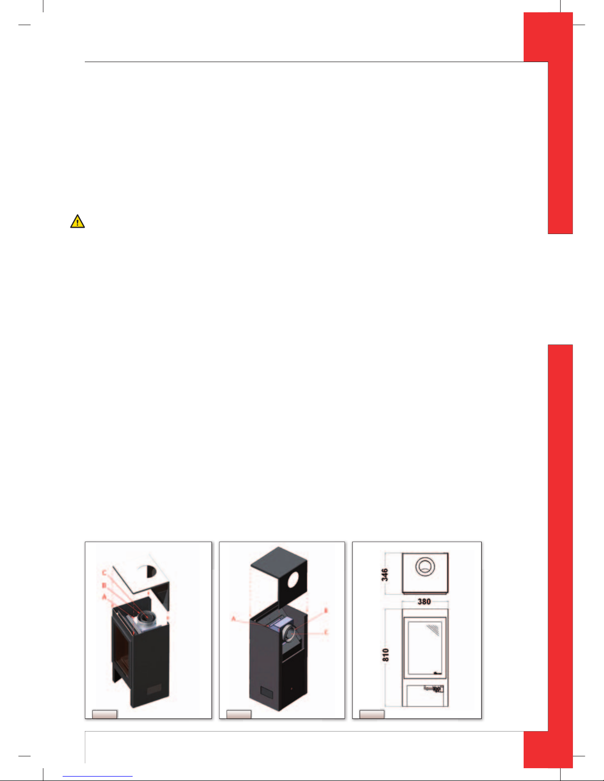
6.4 Reconstructing from top connection appliance to back connection appliance
By default, the appliance is supplied with a top connection (see Fig. 1) for the fl ue gas discharge./ combustion air
supply system. The top connection can be reconstructed to a back connection (see
Fig. 2).
The back connection is required if the appliance is directly connected to a wall duct. In all other cases, the top connection will be used.
UK
95900605 UK Install_G20.indd 495900605 UK Install_G20.indd 4 2-2-10 12:552-2-10 12:55
Page 5
5
English
SOLO - INSTRUCTION FOR INSTALLATION
Proceed as follows, when reconstructing to a back connection:
➠
Take aluminium bend C from the air inlet stub; see Fig. 1;
➠
Unscrew the 8 parkers A from the air inlet stub; see Fig. 1;
➠
Turn air inlet stub B 90 degrees, as indicated in Fig. 2;
➠
Fix the air inlet stub again by using the 8 parkers;
➠
Place back the aluminium bend, as indicated.
!Caution
The upper plate will only be placed when the appliance is on its intended location, as described below in section 6.5.
6.5 Placing the appliance
Place the appliance as follows:
Caution
- Always place the appliance at a minimum distance of 500 mm from combustible objects and/or materials.
- Do not make any changes to the appliance;
- Place the appliance at a distance of at least 50 mm from the back wall;
- Do not cover the appliance and the discharge material and/or do not wrap it in an insulation blanket or any other
material.
➠
Determine the location of the appliance; the dimensions can be found in Fig. 3.
➠
Provide a gas connection at the location. For details, see section 6.3.
➠
Make a duct for the ue gas discharge/combustion air supply system with the following diameters. For details, see
section 6.6.
- Ø160 mm for a wall duct through incombustible material;
- Ø 250 mm for a wall duct through combustible material;
- Ø160 mm for a roof duct through incombustible material;
- Ø 250 mm for a roof duct through combustible material.
➠
Place the appliance on its intended location.
The top plate of the appliance is supplied separately. The opening should be attached to the back by using the back
connection. When using the top connection, the opening will be placed on the top.
!Tip
Avoid damaging the top plate by immediately placing it in the required position.
➠
Place the top plate (see Fig. 1 and 2).
6.6 Flue gas discharge / combustion air supply system
6.6.1 General
The appliance is of the C11/C31 type.
The appliance is connected to a combined fl ue gas discharge/combustion air supply system, hereafter referred to
as the concentric system.
The passage to the outside can be made with a wall duct (see section 6.6.2) or with a roof duct (see section 6.6.3).
If necessary, you can also use an existing discharge channel (see section 6.6.4).
Fig. 1 Fig. 2 Fig. 3
UK
95900605 UK Install_G20.indd 595900605 UK Install_G20.indd 5 2-2-10 12:552-2-10 12:55
Page 6
6
English
SOLO - INSTRUCTION FOR INSTALLATION
Caution
- Only use the concentric system supplied by DRU (Ø100 / Ø150 mm). This system was tested in combination with the
appliance.
DRU cannot guarantee a good and safe operation of other systems and cannot accept liability for them;
- For connecting to an existing chimney ue you should only use the installation set supplied by DRU;
- Always place the concentric system at a minimum distance of 500 mm from combustible objects and/or materials;
- Maintain a distance of at least 50 mm between the concentric system and combustible objects and/or materials.
The concentric system is constructed from (the discharge stump of) the appliance.
If structural circumstances require that the concentric system is placed fi rst, the appliance can later be connected
with a telescopic pipe piece.
!Tip
DRU does not recommend placing the telescopic piece, because this visible pipe piece cannot be supplied in colour
and does not really combine well with the appliance.
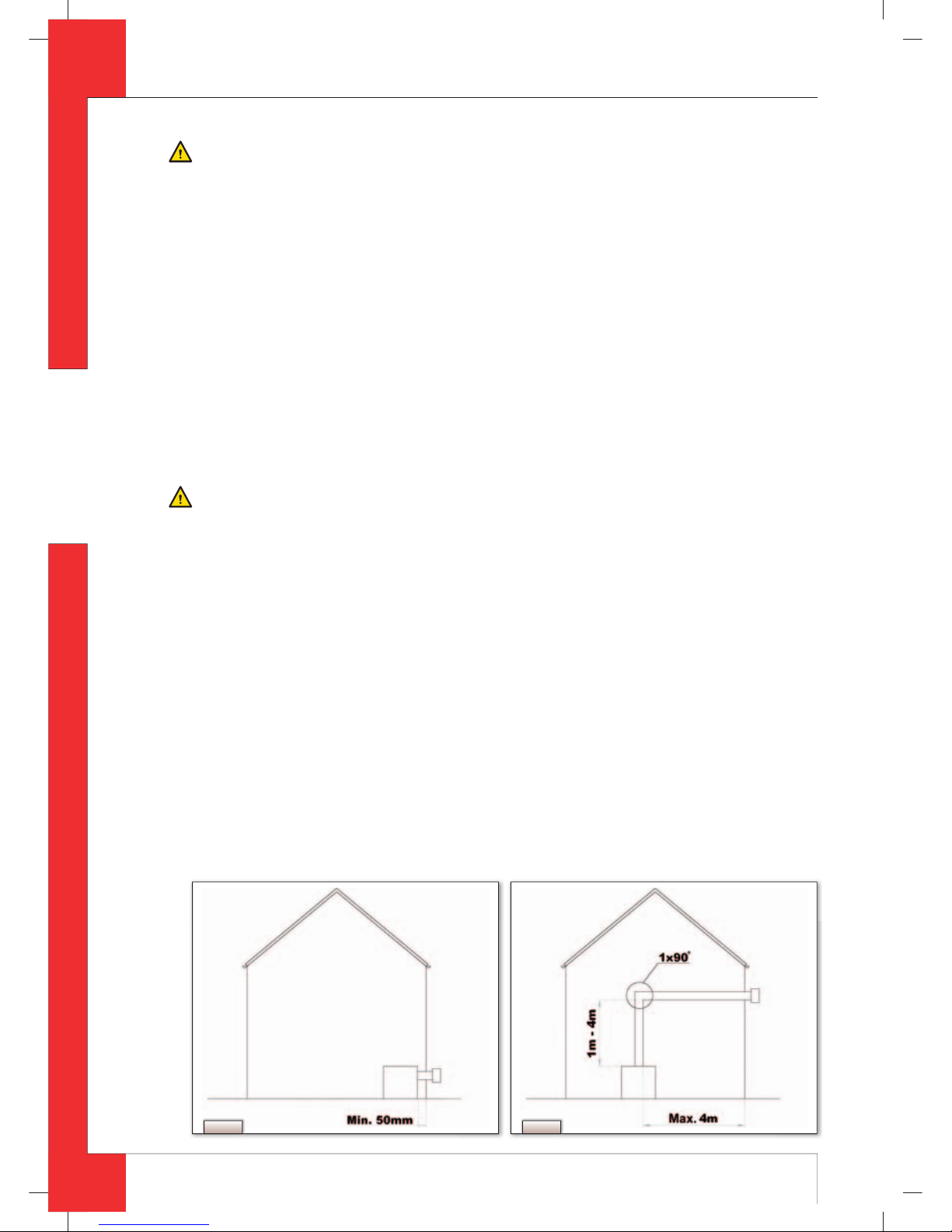
6.6.2 Application with wall duct
There are 2 methods of connecting the appliance to the wall duct:
1. directly onto the wall duct; see
Fig. 4a. In this situation the appliance should be reconstructed to a back connection
(see section 6.4);
2. indirectly onto the wall duct; see
Fig. 4b. Under these circumstances, the top connection of the appliance is
used.
When placing the wall duct, you must take the following aspects into account:
Caution
- Use heat-resistant isolation material when passing through combustible material;
- The rosette (mounting inner plate) of the wall duct is too small to seal the Ø 250 mm opening when passing through
combustible material. That is why you should rst apply a su ciently large heat-resistant intermediate plate to the
wall. Then, the rosette is mounted on the intermediate plate.
!Caution
Some heat-resistant isolation materials contain volatile components that will spread an unpleasant smell for a pro-
longed time; these are not suitable.
Below you will fi nd the conditions for constructing and placing in more detail.
6.6.2.1 Direct connection to the wall duct
If the appliance is directly connected to the duct wall (see Fig. 4a), it will be necessary to change the primary aeration
of the burner. Table 2 contains the conditions for adjusting, and section 6.8, Adjusting the appliance, describes how
the primary aeration can be adjusted. The baffl e will not be placed.
Proceed as follows, when placing the wall duct:
!Caution
The top plate of the appliance is placed with the opening to the back.
➠
Determine the length of the duct;
➠
Make sure the wall duct has the right dimensions.
!Caution
- Make sure that the right insertion length is maintained;
- Place the wall duct with the groove/folded seam at the top;
➠
Mount the rosette (mounting inner plate); if necessary, on a heat resistant intermediate plate when passing through
combustible material;
➠
Attach the wall duct from the outside with four screws in their respective holes.
Fig. 4bFig. 4a
UK
95900605 UK Install_G20.indd 695900605 UK Install_G20.indd 6 2-2-10 12:562-2-10 12:56
Page 7

7
English
SOLO - INSTRUCTION FOR INSTALLATION
6.6.2.2 Indirect connection to the wall duct
The concentric system has to comply with the following conditions (see Fig. 4b):
- First, a concentric pipe of at least 1 meter should be connected vertically to the appliance;
- The total vertical pipe length can have a maximum of 4 meters;
- After the vertical part a bend of 90° is connected;
- The total horizontal pipe length can have a maximum of 4 meters (wall duct excluded).
Under these conditions, the restriction will not be placed.
!Caution
The top plate of the appliance is placed with the opening on the top.
➠
Build the system up from (the connection stump of ) the appliance;
➠
Connect the (lacquered) concentric pipe pieces and the (lacquered) bend;
➠
On each connection, apply a (lacquered) clip binding with silicon sealing ring;
➠
Use a parker to x the clip binding to the pipe on locations that are unreachable after installation;
➠
Apply su cient clamps, so that the weight of the pipes does not only rest on the appliance;
➠
Determine the remaining length of the wall duct;
➠
Make sure the wall duct has the right dimensions.
!Caution
- For G20, the primary aeration burner must be adjusted.
- Make sure that the right insertion length is maintained;
- Place the wall duct with the groove/folded seam at the top;
- Make sure the horizontal concentric pipe pieces are sloping towards the wall duct, in order to prevent rain water
from entering.
➠
Mount the rosette (mounting inner plate); if necessary, on a heat resistant intermediate plate when passing through
combustible material
➠
Attach the wall duct from the outside with four screws in their respective holes.
6.6.3 Application with roof duct
6.6.3.1 Construction of concentric system with roof duct
The concentric system with roof duct has to comply with the following conditions:
- The construction of the chosen system has to be allowed. (See the procedure described below);
- First, a concentric pipe of at least 1 meter should be connected vertically to the appliance.
Depending on the construction, the appliance will be adjusted by means of the baffl e.
In the following procedure you can see how the allowability of a concentric system can be determined and which
settings are needed.
➠
Determine the following data:
1) The number of bends required (no distinction is made between 45° and 90° bends);
2) The total number of meters of horizontal pipe length;
3) The total number of meters of vertical and/or sloping pipe length.
With these data and Table 1 you will be able to determine whether the concentric system is allowed. In Table 2 you
can see which setting the appliance needs.
Proceed as follows:
➠
In the rst 2 columns of Table 1 look for the number of bends required and the total horizontal pipe length;
➠
In the 3rd column of Table 1 look for the total vertical and/or sloping pipe length.
If you end up in a box with the letter A, B, C, D or E, the concentric system chosen by you is allowed.
➠
Use Table 2 to determine which conditions apply for the ba e (for adjusting, see section 6.8).
UK
95900605 UK Install_G20.indd 795900605 UK Install_G20.indd 7 2-2-10 12:562-2-10 12:56
Page 8

8
English
SOLO - INSTRUCTION FOR INSTALLATION
Examples
To clarify, we will give 2 examples to determine the allowability of a concentric system and the conditions for setting
the appliance.
In Table 1 the route to be followed is indicated by arrows. The result is indicated with a circle.
Example 1
1) 2 bends
2) 3 meters horizontal
3) 8 meters vertical/sloping
→ Construction of this concentric system is allowed.
→ Situation C applies for setting the appliance
Example 2
1) 3 bends
2) 4 meters horizontal
3) 9 meters vertical/sloping
→ Construction of this concentric system is not allowed.
Table 1: Conditions for setting appliance with roof duct
G20/25 Total number of
meters horizontal
pipe length
Total number of meters vertical and/or sloping pipe length
1234567
앗8 앗9
10 11 12
no bends 0 B B C C D D EEEEEE
2 bends 0 A A B B C C D D E E E E
1 AABBCCDDEE
2 AABCCCDD
씮
3AABBCC
4 AABB
5
3 bends 0 A A A B B C C D D E E E
1 AAABBCCDDE
2 AAABBCCD
3 AAABBC
씮
4 AAAB
5
4 bends 0 AAAABBCCDDEE
1 AAAABBCCDD
2 AAAABBCC
3 AAAABB
4 AAAA
5
5 bends -
■
■ = construction is not allowed
UK
95900605 UK Install_G20.indd 895900605 UK Install_G20.indd 8 2-2-10 12:562-2-10 12:56
Page 9

9
English
SOLO - INSTRUCTION FOR INSTALLATION
Table 2: Conditions for setting the appliance
Wall duct Primary hole throttle ring Baffl e Distance restriction (mm)
Situation
G25 G20
Only wall duct (direct connection) Ø6 Ø9 NO OPEN
1 - 4 m vertical + bend 90° +
0 - 4 m horizontal + wall duct
(indirect connection)
Ø5 Ø7 NO OPEN
Roof duct Primary hole throttle ring Baffl e Distance restriction (mm)
Situation
G25 G20
A Ø5 Ø7 NO OPEN
B Ø5 Ø7 YES 35
C Ø5 Ø7 YES 31
D Ø5 Ø7 YES 29
E Ø5 Ø7 YES 22
6.6.3.2 Placing concentric system with roof duct
The roof duct can end in a sloping and a fl at roof.
The roof duct can be supplied with an adhesive plate for a fl at roof or with a universally adjustable tile for a sloping
roof.
Place the concentric system as follows:
➠
Build the system up from (the connection stump of ) the appliance.
Caution
- Maintain a distance of at least 50 mm between the outside of the concentric system and the walls and/or the
ceiling;
- Use heat-resistant isolation material when passing through combustible material.
!Caution
Some heat-resistant isolation materials contain volatile components that will spread an unpleasant smell for a
prolonged time; these are not suitable.
➠
Connect the (lacquered) concentric pipe pieces and, if required, the (lacquered) bends;
➠
On each connection, apply a (lacquered) clip binding with silicon sealing ring;
➠
Use a parker to x the clip binding to the pipe on locations that are unreachable after installation;
➠
Apply su cient clamps, so that the weight of the pipes does not only rest on the appliance;
➠
Determine the remaining length of the roof duct;
➠
Make sure the roof duct has the right dimensions.
!Caution
Make sure that the right insertion length is maintained.
➠
Connect the roof duct to the concentric pipes.
!Caution
- Make sure that the universal tile ts well with the surrounding tiles;
- Make sure that the adhesive plate ts well onto the at roof.
6.6.4 Connection of existing chimney fl ue
It is possible to connect the appliance to an existing channel.
A fl exible SS pipe is placed in the chimney for discharging fl ue gases. The surrounding space is used to supply
combustion air.
The following requirements apply when connecting to an existing chimney fl ue:
- only allowed when used in combination with the special DRU chimney installation set.
The installation regulation is also supplied;
- the dimensions should be at least 150 x 150 mm;
- the vertical length has a maximum of 12 meters;
- the horizontal length has a maximum of 3 meters;
- the existing chimney fl ue has to be clean;
- the existing chimney fl ue has to be closed.
For setting the appliance, the same conditions/instructions apply as for the concentric system.
UK
95900605 UK Install_G20.indd 995900605 UK Install_G20.indd 9 2-2-10 12:562-2-10 12:56
Page 10

10
English
SOLO - INSTRUCTION FOR INSTALLATION
6.7 Connecting gas
Use the following procedure when connecting the gas, see section 6.3, Gas Connection:
➠
If necessary, blow through the gas pipe;
➠
Connect the gas pipe with gas tap to the gas control block.
!Caution
- The gas control block is located in the space at the bottom of the appliance;
- Do not turn the gas tap when connecting the gas pipe.
➠
Bleed the gas pipe.
6.8 Adjusting the appliance
The appliance has to be set in such a way that it works correctly in combination with the discharge system.
For that purpose the baffl e is placed and/or the primary aeration is changed; for conditions see section 6.6.2, for
application with wall duct and section 6.6.3 for application with roof duct.
6.8.1 Baffl e
The baffl e is supplied separately.
Proceed as follows when placing the baffl e (see
Fig. 5):
➠
If necessary, remove the pane as described in section 6.10.1;
➠
Remove the ba e plate by unscrewing the socket cap screw;
➠
Place the ba e (R);
➠
Use the template supplied to set the distance of the ba e (see Fig. 6) as follows:
- A distance of 22 mm means that the ba e is closed to a maximum level;
- A distance of 29, 31 and 35 mm is set by using a template.
➠
Fix the ba e by using the socket cap screw (S);
➠
Place back the ba e plate.
6.8.2 Primary aeration of the burner
When the tray surrounding the burner is removed, you can see the throttle ring that is attached to the pipe fi xed to
the burner (see
Fig. 7).
The primary aeration of the burner can be adjusted by rotating the throttle ring.
Below you will fi nd the steps you must follow:
➠
If necessary, remove the pane (see section 6.10.1);
➠
Remove the tray surrounding the burner;
➠
Unscrew the two parkers xing the burner (see Fig. 7, E and F);
➠
Remove the burner;
➠
Unscrew the cap screw xing the throttle ring (see Fig. 7, D);
➠
Rotate the throttle ring until the hole with the correct diameter (5, 6, 7 or 9 mm) is right in front of the 15 mm hole in
the pipe xed to the burner.
!Tip
- The hole with the 15 mm diameter is at the bottom of the pipe to the burner.
➠
Fix the throttle ring again by using the cap screw;
➠
Fix the burner by using screws E and F;
➠
Place back the tray surrounding the burner.
Fig. 7Fig. 6Fig. 5
UK
95900605 UK Install_G20.indd 1095900605 UK Install_G20.indd 10 2-2-10 12:562-2-10 12:56
Page 11

11
English
SOLO - INSTRUCTION FOR INSTALLATION
6.9 Placing wood set
The appliance is supplied with a wood set.
Caution
Strictly observe the following instructions to prevent unsafe situations:
- only ever use the supplied wood set;
- place the wood set exactly as described;
- make sure the pilot burner and the space around it are kept free from objects (see
Fig. 8);
- make sure that the slot between the burner tray and the tray surrounding the burner is kept free from objects.
6.9.1 Wood set
The wood set consists of lava rocks (see Fig. 9), chips (see Fig. 10) and a number of blocks.
➠
Fill the burner tray with lava rocks; equally spread the lava rocks (see Fig. 11);
➠
Fill the tray surrounding the burner with chips; equally spread the chips on the tray surrounding the burner, making
sure the slots are kept as free as possible;
➠
Identify blocks A up to F by using Fig. 12.
!Caution
No chips on the burner.
!Tip
Use the burn stains on the blocks for identi cation.
➠
First place blocks A and B (see Fig. 13);
➠
Then place blocks C and D; see Fig. 14);
➠
Finally place block E; (see Fig. 15).
6.10 Pane
After placing the wood set you can place the pane as described below.
!Caution
Avoid/remove ngerprints on the pane, as they will burn into the glass.
Fig. 8 Fig. 9
Fig. 10 Fig. 11
UK
95900605 UK Install_G20.indd 1195900605 UK Install_G20.indd 11 2-2-10 12:562-2-10 12:56
Page 12

12
English
SOLO - INSTRUCTION FOR INSTALLATION
Fig. 12
Fig. 13
UK
95900605 UK Install_G20.indd 1295900605 UK Install_G20.indd 12 2-2-10 12:562-2-10 12:56
Page 13

13
English
SOLO - INSTRUCTION FOR INSTALLATION
Fig. 14
Fig. 15
UK
95900605 UK Install_G20.indd 1395900605 UK Install_G20.indd 13 2-2-10 12:562-2-10 12:56
Page 14

14
English
SOLO - INSTRUCTION FOR INSTALLATION
6.10.1 Removing the pane
Proceed as follows, to remove the pane:
➠
Push the frame up at the bottom;
➠
Tip the top side to the front;
➠
Remove the frame;
➠
Remove the 4 pane strips from the pane using a screw-
driver (see
Fig. 16 and 17);
➠
Remove the pane.
6.10.2 Mounting the pane
Mounting the pane will take place in reverse order of
the removal procedure described above.
!Tip
First apply the bottom strip, then place the pane, and
then apply the other strips.
7. Operation
See the operating instructions, chapter 4, Operation, for the operation of the appliance.
7.1 Wireless remote control
The wireless remote control consists of a remote control and a receiver.
Below you can read how you should connect the receiver; the operation of the wireless remote control will be discussed in the operating instructions, chapter 4, Operation.
7.1.1 Connecting the receiver
The receiver is placed in the space at the bottom of the appliance.
The gas control block is also placed in this space.
The receiver should be connected to the appliance, before the batteries are installed.
Proceed as follows:
➠
Connect the connecting cable of the receiver to the gas control block (see Fig. 17).
!Tip
The plugs have di erent sizes that correspond with the connectors.
➠
Place the batteries as described below in section 7.1.2;
➠
Place the receiver in its holder, with the sensor to the front, see Fig. 5.
!Caution
Do not place the ignition cable over and/or along metal parts: this will weaken the spark.
7.1.2 Placing / replacing the batteries
Follow the procedure below when placing / replacing the batteries:
➠
Pick up the receiver;
➠
Slide the cover o ;
➠
Place or remove the 4 penlite (AA type) batteries.
!Caution
- Avoid a short circuit between the batteries and metal objects/parts;
- Observe the “+” and “-” poles of the batteries and the holder;
- Use alkaline batteries.
➠
Slide back the cover.
➠
Place the receiver in the holder with the sensor to the front.
!Caution
Batteries are regarded as “small chemical waste” and may therefore not be disposed with the household rubbish.
Fig. 16
UK
95900605 UK Install_G20.indd 1495900605 UK Install_G20.indd 14 2-2-10 12:562-2-10 12:56
Page 15

15
English
SOLO - INSTRUCTION FOR INSTALLATION
8. Final check
In order to check whether the appliance is working properly and safely, you must perform the following checks before
the appliance is used.
8.1 Gastightness
Caution
All connections must be gastight.
!Caution
The gas control block can be subjected to a maximum pressure of 50 mbar.
➠
Check the connections for gastightness.
8.2 Gas pressure / pre-pressure
The burner pressure is set at the factory; see type plate. It is not necessary to check the burner pressure.
The pre-pressure in house installations, however, should be checked, as they can vary.
➠
Check the pre-pressure; see Fig. 18 for the measuring nipple on the gas control block;
➠
Contact the gas company if the pre-pressure is not correct.
8.3 Ignition pilot and main burner
For igniting the pilot and main burner, see the operating instructions, chapter 4, Operation.
Caution
Always wait 5 minutes after the pilot ame has gone out, before you re-ignite the appliance.
8.3.1 Pilot fl ame
➠
Check the ignition of the pilot ame.
- the pilot ame burner should start at the rst attempt.
If the pilot fl ame does not burn:
➠
Check if the ignition sparks:
a) If not, the ignition cable is probably not lying free from metal parts;
b) If it does, there is probably still air in the pipe.
➠
Bleed the pipe and/or;
➠
Lay the ignition cable free from metal parts.
8.3.2 Main burner
The main burner is ignited with button B on the gas control block. Button B can be operated by the remote control
and by hand, see the operating instructions, chapter 4, Operation.
Caution
The burner should ignite smoothly and should not pop as a result of delayed ignition.
➠
Check the function of the main burner from the pilot ame position:
- after opening the gas valve, the main burner should burn within a few seconds.
If the main burner does not burn:
➠
Check if button A on the gas control block is in the position ;
➠
Check if the space surrounding the pilot ame is free from objects;
➠
Check the placement of the wood set;
➠
If necessary, correct the abovementioned failures;
➠
Test the main burner 5x for a good operation.
8.4 Flame image
The fl ame image can only really be assessed when the appliance has been burning for several hours. Volatile components from paint, materials, etc., which evaporate in the fi rst hours, will affect the fl ame image.
➠
Check the ame image.
If the fl ame image is not acceptable, this can be due to:
- the evaporation of volatile substances;
- incorrect placement of the wood set.
➠
If necessary, improve the placement of the wood set.
UK
95900605 UK Install_G20.indd 1595900605 UK Install_G20.indd 15 2-2-10 12:562-2-10 12:56
Page 16

16
English
SOLO - INSTRUCTION FOR INSTALLATION
9. Maintenance
Once a year the appliance should be checked, cleaned and, if necessary, repaired by a competent installer in the fi eld
of atmospheric gas heating.
Check at least whether the appliance is working properly and safely.
Caution
- Close the gas tap when performing maintenance work;
- Check the gastightness after repair;
- After replacing the thermocouple, you should rst tighten the swivel of the gas control block by hand and then give
it another quarter turn with a suitable spanner.
➠
If required, clean the following components:
- the pilot ame burner;
- the combustion room;
- the pane.
!Caution
- Remove/place the pane as described in section 6.10;
- Remove the deposit on the inside of the pane with a damp cloth or a non-abrasive detergent such as copper
polish;
- Avoid/remove ngerprints on the pane, as they will burn into the glass;
- Replace a torn or broken pane as described in chapter 6.10.
Caution
- If necessary, place back the wood set correctly; see section 6.9.
➠
Inspect the ue gas discharge / combustion air supply system
➠
Perform a check as described in chapter 8
10. Delivery
You must explain to the user how he should operate the appliance. You should instruct her/him for instance on using
the appliance for the fi rst time, the operation of the remote control, annual maintenance.
Caution
- Tell the user to close the gas tap immediately in case of malfunctions/bad performance and contact the installer in
order to prevent dangerous situations;
- Indicate the location of the gas tap.
➠
Instruct the user about the appliance and the remote control;
➠
When the appliance is started for the rst time, point out that:
- when the appliance is stoked up for the rst time, volatile components evaporate from paint, materials, etc.;
- when evaporating the appliance should preferably be set at its highest level;
- the room should be well ventilated.
➠
Give the operating instructions and instructions for installation to the user (the instructions for installation should be
kept near the appliance).
UK
95900605 UK Install_G20.indd 1695900605 UK Install_G20.indd 16 2-2-10 12:562-2-10 12:56
Page 17

17
English
SOLO - INSTRUCTION FOR INSTALLATION
11. Malfunctions
In the following table you will fi nd an overview of malfunctions that might occur, the possible causes and the remedies
Table 3: Diagnosis of malfunctions
Problem Possible cause Remedy
A. No transmission
(motor will not run)
1. Empty batteries.
2. Receiver is damaged.
3. Remote control is damaged.
4. Motor cable at gas control
block is broken.
1. Replace batteries.
!Caution
Avoid short circuit between the batteries
and metal parts of the appliances.
2. Replace the receiver.
3. Replace the remote control.
4. Replace the motor cable.
B. No ignition (spark) 1. Ignition cable runs over and/or
alongside metal parts.
2. Ignition pen corroded.
1. Do not place the ignition cable over and/or
along metal parts. This will weaken the spark.
If necessary, replace the ignition cable.
2. Replace the ignition pen.
C. No pilot fl ame 1. Air in the pilot fl ame pipe.
2. No spark at the pilot fl ame
burner.
3. Injector is blocked up
1. Flush the pipe or start the ignition process
several times.
2. Check if the ignition cable is lying free from
metal parts.
- If necessary, move it away from the metal
parts.
- If necessary, replace the ignition cable
- If necessary, replace the ignition pen
3.1 Clean the injector
3.2 If necessary, replace the injector
D. Pilot fl ame is burning,
but there is no gas fl ow
to the main burner
1. Button A on the gas control
block is in position
.
2. Button B on the gas control
block is on pilot fl ame position
(●; see
Fig. 18).
3. Pre-pressure of the gas is too
low.
4. Damaged magnet valve.
1. Turn button A to the position
see Fig. 18
2. Increase fl ame height by turning button B
counter-clockwise or by pressing on button ▲
of the remote control.
3. Check the pre-pressure.
If necessary, activate energy mode.
4. Replace the gas control block.
Fig. 17 Fig. 18
UK
95900605 UK Install_G20.indd 1795900605 UK Install_G20.indd 17 2-2-10 12:562-2-10 12:56
Page 18

18
English
SOLO - INSTRUCTION FOR INSTALLATION
Appendix 1 Parts included with the delivery
In the following table you can fi nd the parts that are supplied with the appliance.
Table 4: Parts included with the delivery
Part Quantity Order number
Wood set 1x 806709
Instructions for installation 1x 95900605
Operating instructions 1x 95800402
Setting template for baffl e 1x 38714508
Top plate appliance 1x 38724402
Remote control with receiver 1x 806760
9V block battery 1x 923001
Penlite battery (AA type) 4x 923100
Squeeze coupling 15 mm x G3/8” 1x 805481
Baffl e 1x 38741444
Socket spanner 1x 790811
Appendix 2 Technical data
In the following table you can fi nd the technical data.
Table 5: Technical Data
Type
C11/C31
Type of gas G25 G20
Burner pressure mbar 24,2 19,3
Nom. load (Hs) kW 4,5 4,9
Nom. load (Hi) kW 4,1 4,4
Nom. output kW 3,2 4
Consumption L/h 490 460
Burner injector mm Ø 1,6 Ø 1,6
Consumption on low output L/h 201 184
Low setting injector mm Ø 1,1 Ø1,1
Pilot fl ame injector Code 51 51
Effi ciency class 2 2
Appendix 3 Parts
Parts can be ordered through your dealer
UK
95900605 UK Install_G20.indd 1895900605 UK Install_G20.indd 18 2-2-10 12:562-2-10 12:56
Page 19

19
English
SOLO - INSTRUCTION FOR INSTALLATION
Notes
. . . . . . . . . . . . . . . . . . . . . . . . . . . . . . . . . . . . . . . . . . . . . . . . . . . . . . . . . . . . . . . . . . . . . . . . . . . . . . . . . . . . . . . . . . . . . . . . . . . . . . . . . . . . . . . . . . . . . . . . . . . . . . . . . . . . . . . . . . . . . . . . . . . . . . . . . . . . . . . . . . . . . . . . . . . . . . . . . . . . . . . . . . . . . . . . . . . . . . . . . . . . . . . . . . . .
. . . . . . . . . . . . . . . . . . . . . . . . . . . . . . . . . . . . . . . . . . . . . . . . . . . . . . . . . . . . . . . . . . . . . . . . . . . . . . . . . . . . . . . . . . . . . . . . . . . . . . . . . . . . . . . . . . . . . . . . . . . . . . . . . . . . . . . . . . . . . . . . . . . . . . . . . . . . . . . . . . . . . . . . . . . . . . . . . . . . . . . . . . . . . . . . . . . . . . . . . . . . . . . . . . . .
. . . . . . . . . . . . . . . . . . . . . . . . . . . . . . . . . . . . . . . . . . . . . . . . . . . . . . . . . . . . . . . . . . . . . . . . . . . . . . . . . . . . . . . . . . . . . . . . . . . . . . . . . . . . . . . . . . . . . . . . . . . . . . . . . . . . . . . . . . . . . . . . . . . . . . . . . . . . . . . . . . . . . . . . . . . . . . . . . . . . . . . . . . . . . . . . . . . . . . . . . . . . . . . . . . . .
. . . . . . . . . . . . . . . . . . . . . . . . . . . . . . . . . . . . . . . . . . . . . . . . . . . . . . . . . . . . . . . . . . . . . . . . . . . . . . . . . . . . . . . . . . . . . . . . . . . . . . . . . . . . . . . . . . . . . . . . . . . . . . . . . . . . . . . . . . . . . . . . . . . . . . . . . . . . . . . . . . . . . . . . . . . . . . . . . . . . . . . . . . . . . . . . . . . . . . . . . . . . . . . . . . . .
. . . . . . . . . . . . . . . . . . . . . . . . . . . . . . . . . . . . . . . . . . . . . . . . . . . . . . . . . . . . . . . . . . . . . . . . . . . . . . . . . . . . . . . . . . . . . . . . . . . . . . . . . . . . . . . . . . . . . . . . . . . . . . . . . . . . . . . . . . . . . . . . . . . . . . . . . . . . . . . . . . . . . . . . . . . . . . . . . . . . . . . . . . . . . . . . . . . . . . . . . . . . . . . . . . . .
. . . . . . . . . . . . . . . . . . . . . . . . . . . . . . . . . . . . . . . . . . . . . . . . . . . . . . . . . . . . . . . . . . . . . . . . . . . . . . . . . . . . . . . . . . . . . . . . . . . . . . . . . . . . . . . . . . . . . . . . . . . . . . . . . . . . . . . . . . . . . . . . . . . . . . . . . . . . . . . . . . . . . . . . . . . . . . . . . . . . . . . . . . . . . . . . . . . . . . . . . . . . . . . . . . . .
. . . . . . . . . . . . . . . . . . . . . . . . . . . . . . . . . . . . . . . . . . . . . . . . . . . . . . . . . . . . . . . . . . . . . . . . . . . . . . . . . . . . . . . . . . . . . . . . . . . . . . . . . . . . . . . . . . . . . . . . . . . . . . . . . . . . . . . . . . . . . . . . . . . . . . . . . . . . . . . . . . . . . . . . . . . . . . . . . . . . . . . . . . . . . . . . . . . . . . . . . . . . . . . . . . . .
. . . . . . . . . . . . . . . . . . . . . . . . . . . . . . . . . . . . . . . . . . . . . . . . . . . . . . . . . . . . . . . . . . . . . . . . . . . . . . . . . . . . . . . . . . . . . . . . . . . . . . . . . . . . . . . . . . . . . . . . . . . . . . . . . . . . . . . . . . . . . . . . . . . . . . . . . . . . . . . . . . . . . . . . . . . . . . . . . . . . . . . . . . . . . . . . . . . . . . . . . . . . . . . . . . . .
. . . . . . . . . . . . . . . . . . . . . . . . . . . . . . . . . . . . . . . . . . . . . . . . . . . . . . . . . . . . . . . . . . . . . . . . . . . . . . . . . . . . . . . . . . . . . . . . . . . . . . . . . . . . . . . . . . . . . . . . . . . . . . . . . . . . . . . . . . . . . . . . . . . . . . . . . . . . . . . . . . . . . . . . . . . . . . . . . . . . . . . . . . . . . . . . . . . . . . . . . . . . . . . . . . . .
. . . . . . . . . . . . . . . . . . . . . . . . . . . . . . . . . . . . . . . . . . . . . . . . . . . . . . . . . . . . . . . . . . . . . . . . . . . . . . . . . . . . . . . . . . . . . . . . . . . . . . . . . . . . . . . . . . . . . . . . . . . . . . . . . . . . . . . . . . . . . . . . . . . . . . . . . . . . . . . . . . . . . . . . . . . . . . . . . . . . . . . . . . . . . . . . . . . . . . . . . . . . . . . . . . . .
. . . . . . . . . . . . . . . . . . . . . . . . . . . . . . . . . . . . . . . . . . . . . . . . . . . . . . . . . . . . . . . . . . . . . . . . . . . . . . . . . . . . . . . . . . . . . . . . . . . . . . . . . . . . . . . . . . . . . . . . . . . . . . . . . . . . . . . . . . . . . . . . . . . . . . . . . . . . . . . . . . . . . . . . . . . . . . . . . . . . . . . . . . . . . . . . . . . . . . . . . . . . . . . . . . . .
. . . . . . . . . . . . . . . . . . . . . . . . . . . . . . . . . . . . . . . . . . . . . . . . . . . . . . . . . . . . . . . . . . . . . . . . . . . . . . . . . . . . . . . . . . . . . . . . . . . . . . . . . . . . . . . . . . . . . . . . . . . . . . . . . . . . . . . . . . . . . . . . . . . . . . . . . . . . . . . . . . . . . . . . . . . . . . . . . . . . . . . . . . . . . . . . . . . . . . . . . . . . . . . . . . . .
. . . . . . . . . . . . . . . . . . . . . . . . . . . . . . . . . . . . . . . . . . . . . . . . . . . . . . . . . . . . . . . . . . . . . . . . . . . . . . . . . . . . . . . . . . . . . . . . . . . . . . . . . . . . . . . . . . . . . . . . . . . . . . . . . . . . . . . . . . . . . . . . . . . . . . . . . . . . . . . . . . . . . . . . . . . . . . . . . . . . . . . . . . . . . . . . . . . . . . . . . . . . . . . . . . . .
. . . . . . . . . . . . . . . . . . . . . . . . . . . . . . . . . . . . . . . . . . . . . . . . . . . . . . . . . . . . . . . . . . . . . . . . . . . . . . . . . . . . . . . . . . . . . . . . . . . . . . . . . . . . . . . . . . . . . . . . . . . . . . . . . . . . . . . . . . . . . . . . . . . . . . . . . . . . . . . . . . . . . . . . . . . . . . . . . . . . . . . . . . . . . . . . . . . . . . . . . . . . . . . . . . . .
. . . . . . . . . . . . . . . . . . . . . . . . . . . . . . . . . . . . . . . . . . . . . . . . . . . . . . . . . . . . . . . . . . . . . . . . . . . . . . . . . . . . . . . . . . . . . . . . . . . . . . . . . . . . . . . . . . . . . . . . . . . . . . . . . . . . . . . . . . . . . . . . . . . . . . . . . . . . . . . . . . . . . . . . . . . . . . . . . . . . . . . . . . . . . . . . . . . . . . . . . . . . . . . . . . . .
. . . . . . . . . . . . . . . . . . . . . . . . . . . . . . . . . . . . . . . . . . . . . . . . . . . . . . . . . . . . . . . . . . . . . . . . . . . . . . . . . . . . . . . . . . . . . . . . . . . . . . . . . . . . . . . . . . . . . . . . . . . . . . . . . . . . . . . . . . . . . . . . . . . . . . . . . . . . . . . . . . . . . . . . . . . . . . . . . . . . . . . . . . . . . . . . . . . . . . . . . . . . . . . . . . . .
. . . . . . . . . . . . . . . . . . . . . . . . . . . . . . . . . . . . . . . . . . . . . . . . . . . . . . . . . . . . . . . . . . . . . . . . . . . . . . . . . . . . . . . . . . . . . . . . . . . . . . . . . . . . . . . . . . . . . . . . . . . . . . . . . . . . . . . . . . . . . . . . . . . . . . . . . . . . . . . . . . . . . . . . . . . . . . . . . . . . . . . . . . . . . . . . . . . . . . . . . . . . . . . . . . . .
. . . . . . . . . . . . . . . . . . . . . . . . . . . . . . . . . . . . . . . . . . . . . . . . . . . . . . . . . . . . . . . . . . . . . . . . . . . . . . . . . . . . . . . . . . . . . . . . . . . . . . . . . . . . . . . . . . . . . . . . . . . . . . . . . . . . . . . . . . . . . . . . . . . . . . . . . . . . . . . . . . . . . . . . . . . . . . . . . . . . . . . . . . . . . . . . . . . . . . . . . . . . . . . . . . . .
. . . . . . . . . . . . . . . . . . . . . . . . . . . . . . . . . . . . . . . . . . . . . . . . . . . . . . . . . . . . . . . . . . . . . . . . . . . . . . . . . . . . . . . . . . . . . . . . . . . . . . . . . . . . . . . . . . . . . . . . . . . . . . . . . . . . . . . . . . . . . . . . . . . . . . . . . . . . . . . . . . . . . . . . . . . . . . . . . . . . . . . . . . . . . . . . . . . . . . . . . . . . . . . . . . . .
. . . . . . . . . . . . . . . . . . . . . . . . . . . . . . . . . . . . . . . . . . . . . . . . . . . . . . . . . . . . . . . . . . . . . . . . . . . . . . . . . . . . . . . . . . . . . . . . . . . . . . . . . . . . . . . . . . . . . . . . . . . . . . . . . . . . . . . . . . . . . . . . . . . . . . . . . . . . . . . . . . . . . . . . . . . . . . . . . . . . . . . . . . . . . . . . . . . . . . . . . . . . . . . . . . . .
. . . . . . . . . . . . . . . . . . . . . . . . . . . . . . . . . . . . . . . . . . . . . . . . . . . . . . . . . . . . . . . . . . . . . . . . . . . . . . . . . . . . . . . . . . . . . . . . . . . . . . . . . . . . . . . . . . . . . . . . . . . . . . . . . . . . . . . . . . . . . . . . . . . . . . . . . . . . . . . . . . . . . . . . . . . . . . . . . . . . . . . . . . . . . . . . . . . . . . . . . . . . . . . . . . . .
. . . . . . . . . . . . . . . . . . . . . . . . . . . . . . . . . . . . . . . . . . . . . . . . . . . . . . . . . . . . . . . . . . . . . . . . . . . . . . . . . . . . . . . . . . . . . . . . . . . . . . . . . . . . . . . . . . . . . . . . . . . . . . . . . . . . . . . . . . . . . . . . . . . . . . . . . . . . . . . . . . . . . . . . . . . . . . . . . . . . . . . . . . . . . . . . . . . . . . . . . . . . . . . . . . . .
. . . . . . . . . . . . . . . . . . . . . . . . . . . . . . . . . . . . . . . . . . . . . . . . . . . . . . . . . . . . . . . . . . . . . . . . . . . . . . . . . . . . . . . . . . . . . . . . . . . . . . . . . . . . . . . . . . . . . . . . . . . . . . . . . . . . . . . . . . . . . . . . . . . . . . . . . . . . . . . . . . . . . . . . . . . . . . . . . . . . . . . . . . . . . . . . . . . . . . . . . . . . . . . . . . . .
. . . . . . . . . . . . . . . . . . . . . . . . . . . . . . . . . . . . . . . . . . . . . . . . . . . . . . . . . . . . . . . . . . . . . . . . . . . . . . . . . . . . . . . . . . . . . . . . . . . . . . . . . . . . . . . . . . . . . . . . . . . . . . . . . . . . . . . . . . . . . . . . . . . . . . . . . . . . . . . . . . . . . . . . . . . . . . . . . . . . . . . . . . . . . . . . . . . . . . . . . . . . . . . . . . . .
. . . . . . . . . . . . . . . . . . . . . . . . . . . . . . . . . . . . . . . . . . . . . . . . . . . . . . . . . . . . . . . . . . . . . . . . . . . . . . . . . . . . . . . . . . . . . . . . . . . . . . . . . . . . . . . . . . . . . . . . . . . . . . . . . . . . . . . . . . . . . . . . . . . . . . . . . . . . . . . . . . . . . . . . . . . . . . . . . . . . . . . . . . . . . . . . . . . . . . . . . . . . . . . . . . . .
. . . . . . . . . . . . . . . . . . . . . . . . . . . . . . . . . . . . . . . . . . . . . . . . . . . . . . . . . . . . . . . . . . . . . . . . . . . . . . . . . . . . . . . . . . . . . . . . . . . . . . . . . . . . . . . . . . . . . . . . . . . . . . . . . . . . . . . . . . . . . . . . . . . . . . . . . . . . . . . . . . . . . . . . . . . . . . . . . . . . . . . . . . . . . . . . . . . . . . . . . . . . . . . . . . . .
. . . . . . . . . . . . . . . . . . . . . . . . . . . . . . . . . . . . . . . . . . . . . . . . . . . . . . . . . . . . . . . . . . . . . . . . . . . . . . . . . . . . . . . . . . . . . . . . . . . . . . . . . . . . . . . . . . . . . . . . . . . . . . . . . . . . . . . . . . . . . . . . . . . . . . . . . . . . . . . . . . . . . . . . . . . . . . . . . . . . . . . . . . . . . . . . . . . . . . . . . . . . . . . . . . . .
. . . . . . . . . . . . . . . . . . . . . . . . . . . . . . . . . . . . . . . . . . . . . . . . . . . . . . . . . . . . . . . . . . . . . . . . . . . . . . . . . . . . . . . . . . . . . . . . . . . . . . . . . . . . . . . . . . . . . . . . . . . . . . . . . . . . . . . . . . . . . . . . . . . . . . . . . . . . . . . . . . . . . . . . . . . . . . . . . . . . . . . . . . . . . . . . . . . . . . . . . . . . . . . . . . . .
. . . . . . . . . . . . . . . . . . . . . . . . . . . . . . . . . . . . . . . . . . . . . . . . . . . . . . . . . . . . . . . . . . . . . . . . . . . . . . . . . . . . . . . . . . . . . . . . . . . . . . . . . . . . . . . . . . . . . . . . . . . . . . . . . . . . . . . . . . . . . . . . . . . . . . . . . . . . . . . . . . . . . . . . . . . . . . . . . . . . . . . . . . . . . . . . . . . . . . . . . . . . . . . . . . . .
. . . . . . . . . . . . . . . . . . . . . . . . . . . . . . . . . . . . . . . . . . . . . . . . . . . . . . . . . . . . . . . . . . . . . . . . . . . . . . . . . . . . . . . . . . . . . . . . . . . . . . . . . . . . . . . . . . . . . . . . . . . . . . . . . . . . . . . . . . . . . . . . . . . . . . . . . . . . . . . . . . . . . . . . . . . . . . . . . . . . . . . . . . . . . . . . . . . . . . . . . . . . . . . . . . . .
. . . . . . . . . . . . . . . . . . . . . . . . . . . . . . . . . . . . . . . . . . . . . . . . . . . . . . . . . . . . . . . . . . . . . . . . . . . . . . . . . . . . . . . . . . . . . . . . . . . . . . . . . . . . . . . . . . . . . . . . . . . . . . . . . . . . . . . . . . . . . . . . . . . . . . . . . . . . . . . . . . . . . . . . . . . . . . . . . . . . . . . . . . . . . . . . . . . . . . . . . . . . . . . . . . . .
. . . . . . . . . . . . . . . . . . . . . . . . . . . . . . . . . . . . . . . . . . . . . . . . . . . . . . . . . . . . . . . . . . . . . . . . . . . . . . . . . . . . . . . . . . . . . . . . . . . . . . . . . . . . . . . . . . . . . . . . . . . . . . . . . . . . . . . . . . . . . . . . . . . . . . . . . . . . . . . . . . . . . . . . . . . . . . . . . . . . . . . . . . . . . . . . . . . . . . . . . . . . . . . . . . . .
. . . . . . . . . . . . . . . . . . . . . . . . . . . . . . . . . . . . . . . . . . . . . . . . . . . . . . . . . . . . . . . . . . . . . . . . . . . . . . . . . . . . . . . . . . . . . . . . . . . . . . . . . . . . . . . . . . . . . . . . . . . . . . . . . . . . . . . . . . . . . . . . . . . . . . . . . . . . . . . . . . . . . . . . . . . . . . . . . . . . . . . . . . . . . . . . . . . . . . . . . . . . . . . . . . . .
. . . . . . . . . . . . . . . . . . . . . . . . . . . . . . . . . . . . . . . . . . . . . . . . . . . . . . . . . . . . . . . . . . . . . . . . . . . . . . . . . . . . . . . . . . . . . . . . . . . . . . . . . . . . . . . . . . . . . . . . . . . . . . . . . . . . . . . . . . . . . . . . . . . . . . . . . . . . . . . . . . . . . . . . . . . . . . . . . . . . . . . . . . . . . . . . . . . . . . . . . . . . . . . . . . . .
. . . . . . . . . . . . . . . . . . . . . . . . . . . . . . . . . . . . . . . . . . . . . . . . . . . . . . . . . . . . . . . . . . . . . . . . . . . . . . . . . . . . . . . . . . . . . . . . . . . . . . . . . . . . . . . . . . . . . . . . . . . . . . . . . . . . . . . . . . . . . . . . . . . . . . . . . . . . . . . . . . . . . . . . . . . . . . . . . . . . . . . . . . . . . . . . . . . . . . . . . . . . . . . . . . . .
. . . . . . . . . . . . . . . . . . . . . . . . . . . . . . . . . . . . . . . . . . . . . . . . . . . . . . . . . . . . . . . . . . . . . . . . . . . . . . . . . . . . . . . . . . . . . . . . . . . . . . . . . . . . . . . . . . . . . . . . . . . . . . . . . . . . . . . . . . . . . . . . . . . . . . . . . . . . . . . . . . . . . . . . . . . . . . . . . . . . . . . . . . . . . . . . . . . . . . . . . . . . . . . . . . . .
. . . . . . . . . . . . . . . . . . . . . . . . . . . . . . . . . . . . . . . . . . . . . . . . . . . . . . . . . . . . . . . . . . . . . . . . . . . . . . . . . . . . . . . . . . . . . . . . . . . . . . . . . . . . . . . . . . . . . . . . . . . . . . . . . . . . . . . . . . . . . . . . . . . . . . . . . . . . . . . . . . . . . . . . . . . . . . . . . . . . . . . . . . . . . . . . . . . . . . . . . . . . . . . . . . . .
. . . . . . . . . . . . . . . . . . . . . . . . . . . . . . . . . . . . . . . . . . . . . . . . . . . . . . . . . . . . . . . . . . . . . . . . . . . . . . . . . . . . . . . . . . . . . . . . . . . . . . . . . . . . . . . . . . . . . . . . . . . . . . . . . . . . . . . . . . . . . . . . . . . . . . . . . . . . . . . . . . . . . . . . . . . . . . . . . . . . . . . . . . . . . . . . . . . . . . . . . . . . . . . . . . . .
. . . . . . . . . . . . . . . . . . . . . . . . . . . . . . . . . . . . . . . . . . . . . . . . . . . . . . . . . . . . . . . . . . . . . . . . . . . . . . . . . . . . . . . . . . . . . . . . . . . . . . . . . . . . . . . . . . . . . . . . . . . . . . . . . . . . . . . . . . . . . . . . . . . . . . . . . . . . . . . . . . . . . . . . . . . . . . . . . . . . . . . . . . . . . . . . . . . . . . . . . . . . . . . . . . . .
UK
95900605 UK Install_G20.indd 1995900605 UK Install_G20.indd 19 2-2-10 12:562-2-10 12:56
Page 20

959.006.05.UK
95900605 UK Install_G20.indd 2095900605 UK Install_G20.indd 20 2-2-10 12:562-2-10 12:56
 Loading...