

Page 1

INSTALLATIEVOORSCHRIFT EN GEBRUIKERSHANDLEIDING
INSTRUCTIONS FOR INSTALLATION AND OPERATION
INSTALLATIONSVORSCHRIFT UND GEBRAUCHSANWEISUNG
INSTRUCTIONS D’INSTALLATION ET MODE D’EMPLOI
ESTATE 02
CASTELLO 02
Bewaar dit document zorgvuldig
Please retain this document carefully
Bewahren Sie dieses Dokument sorgfältig auf
Conservez soigneusement cette notice
957.575.00
DRU VER W ARMING B.V.
HOLLAND
Page 2
50
min. 670
350
390
350
615
670
675
25
max. 720
38c-1065
679
350
390
615
673
350
max. 720
min. 670
29
50
38c-1066
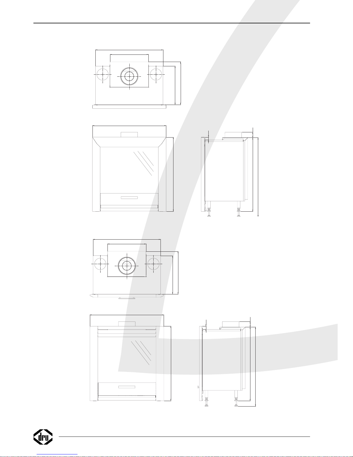
Fig. 1 Estate 02
Fig. 2 Castello 02
Page 3

Belangrijk
• De boezem dient "belucht" en "ontlucht" te worden.
• Het is niet toegestaan het toestel in de schouw te voorzien van een isolatie deken o.i.d.
• Voordat men het toestel in gebruik neemt dient u altijd de ruit schoon te maken,
dit om inbranden van evt. verontreinigingen, zoals vingerafdrukken tegen te gaan.
Important
• The chimney breast should be adequately vented.
• It is not allowed to wrap a built in appliance in any kind of isolation material.
• Always clean the glass pane before using the gas fire, to prevent any finger marks or other
dirt getting burnt into the glass.
Wichtig
• Der Kaminüberbau muss "belüftet" und "entlüftet" werden.
• Es ist nicht erlaubt ein eingebautes Gerät in Isolationsmaterial zu wickeln.
• Bevor man das Gerät in Gebrauch nimmt, muss man erst die Scheibe säubern. Dies um
einbrennen von evt.Verunreinigungen, wie Fingerabdrücken zu vermeiden.
Important
• Le manteau doit être « ventilé » et « purgé ».
• L'appareil, lors de son installation dans la cheminée, ne peut en aucun cas être recouvert
d'un matériel isolant!!!
• Il est impératif de nettoyer la vitre avant d’utiliser l’appareil, ceci afin d’éviter la combustion
d’éventuelles salissures, comme les traces de doigt.
Estate / Castello
Page 4

Page 5
Nederlands
INHOUD
Woord vooraf . . . . . . . . . . . . . . . . . . . . . . . . . . . . . .2
Uitpakken . . . . . . . . . . . . . . . . . . . . . . . . . . . . . . . . .2
Aansluiten . . . . . . . . . . . . . . . . . . . . . . . . . . . . . . . . .2
Installatievoorschrift . . . . . . . . . . . . . . . . . . . . . . . . .2
Gassoort . . . . . . . . . . . . . . . . . . . . . . . . . . . . . . . . .2
Belangrijk . . . . . . . . . . . . . . . . . . . . . . . . . . . . . . . . .2
Plaatsen van het toestel . . . . . . . . . . . . . . . . . . . . . .3
Plaatsen van het toestel in een nieuwe schouw . . . .3
Boezemijzer . . . . . . . . . . . . . . . . . . . . . . . . . . . . . . .3
Aansluiting voor convectielucht . . . . . . . . . . . . . . . .3
Aansluitmogelijkheden . . . . . . . . . . . . . . . . . . . . . . .3
Voorbereidingen voor het plaatsen van
het in- en uitlaatsysteem . . . . . . . . . . . . . . . . . . . . . .4
Geveldoorvoer met concentrische pijpen . . . . . . . .4
Dakdoorvoer met concentrische pijpen . . . . . . . . . .4
Bestaande schoorsteen . . . . . . . . . . . . . . . . . . . . . . .4
Instellingen restrictieschuif . . . . . . . . . . . . . . . . . . . .4
Bij dakdoorvoer . . . . . . . . . . . . . . . . . . . . . . . . . . . .4
Bij geveldoorvoer . . . . . . . . . . . . . . . . . . . . . . . . . . .5
Aansluiting van de gastoevoer . . . . . . . . . . . . . . . . . .5
Plaatsen van de houtblokken . . . . . . . . . . . . . . . . . . .5
Verlengplaten monteren . . . . . . . . . . . . . . . . . . . . . .5
Glasraam monteren . . . . . . . . . . . . . . . . . . . . . . . . .5
Frontpaneel monteren . . . . . . . . . . . . . . . . . . . . . . .6
Draadloze bediening . . . . . . . . . . . . . . . . . . . . . . . . .6
Aansluiten van de ontvanger . . . . . . . . . . . . . . . . . . .6
Vervangen van de batterijen in de ontvanger . . . . . .6
Plaatsen of vervangen van de batterijen
in de afstandsbediening . . . . . . . . . . . . . . . . . . . . . . .6
Gebruikershandleiding . . . . . . . . . . . . . . . . . . . . . . .6
Aansteken . . . . . . . . . . . . . . . . . . . . . . . . . . . . . . . . .6
Afstandsbediening . . . . . . . . . . . . . . . . . . . . . . . . . . .7
Waakvlamstand . . . . . . . . . . . . . . . . . . . . . . . . . . . . .7
Uitschakelen . . . . . . . . . . . . . . . . . . . . . . . . . . . . . . .7
Belangrijk . . . . . . . . . . . . . . . . . . . . . . . . . . . . . . . . .7
Algemene opmerkingen . . . . . . . . . . . . . . . . . . . . . .7
Onderhoud en reiniging . . . . . . . . . . . . . . . . . . . . . .7
Verkleuring van wanden en plafonds . . . . . . . . . . . . .7
Eerste maal stoken . . . . . . . . . . . . . . . . . . . . . . . . . .8
Extra bescherming . . . . . . . . . . . . . . . . . . . . . . . . . .8
Afdanken . . . . . . . . . . . . . . . . . . . . . . . . . . . . . . . . .8
Garantie . . . . . . . . . . . . . . . . . . . . . . . . . . . . . . . . . .8
(Voor België de garantiekaart op blz. 25 en 31 invullen)
Technische gegevens . . . . . . . . . . . . . . . . . . . . . . . .35
Estate / Castello
INHOUD
1
Garantiebepalingen
• DRU Verwarming B.V. garandeert de goede werking van het toestel en staat er voor in dat het toestel met de grootste zorg is vervaardigd van deugdelijk
materiaal.
• De garantie geldt gedurende 1 jaar na datum van aankoop.
• Onder de garantie vallen alle gebreken, die een gevolg zijn van fouten in de constructie of voor de constructie gebruikte onderdelen.
• DRU Verwarming verplicht zich gedurende de garantieperiode gratis vervangende onderdelen te leveren. Het 1ste jaar van de garantietermijn zullen - dit
ter beoordeling van DRU Verwarming B.V. - geen kosten in rekening worden gebracht.
• De garantie vervalt als storingen het gevolg zijn van foutieve installatie, van verkeerd gebruik of onderhoud van onderdelenvervanging door andere dan
originele onderdelen of van plaatsing of reparaties door onbevoegden.
• Indien het opsturen van het apparaat naar de fabriek noodzakelijk is dient dit franco te gebeuren.Het garantiebewijs s.v.p. meesturen.
• Wanneer u aanspraak wilt maken op fabrieksgarantie, wilt u dan eerst contact opnemen met uw installateur.
• Wilt u bij uw garantiebewijs ook de rekening van uw leverancier bewaren. Bij serviceverlening zal men hier naar vragen.
DRU Verwarming B.V.
GARANTIEBEWIJS
Wilt u dit garantiebewijs volledig invullen en samen met de rekening bij uw toestel bewaren.
Invullen in blokletters s.v.p.
Type: . . . . . . . . . . . . . . . . . . . . . . . . . . . . . . . . . Aankoopdatum: . . . . . . . . . . . . . . . . . . . . . . . . . .
Kleur: . . . . . . . . . . . . . . . . . . . . . . . . . . . . . . . . . Serienummer (op typeplaat): . . . . . . . . . . . . . . . .
Koper: Leverancier:
Naam . . . . . . . . . . . . . . . . . . . . . . . . . . . . . . . . . Naam . . . . . . . . . . . . . . . . . . . . . . . . . . . . . . . . .
Adres . . . . . . . . . . . . . . . . . . . . . . . . . . . . . . . . . Adres . . . . . . . . . . . . . . . . . . . . . . . . . . . . . . . . .
Postcode . . . . . . . . . . . . . . . . . . . . . . . . . . . . . . Postcode . . . . . . . . . . . . . . . . . . . . . . . . . . . . . . .
Plaats . . . . . . . . . . . . . . . . . . . . . . . . . . . . . . . . . Plaats . . . . . . . . . . . . . . . . . . . . . . . . . . . . . . . . . .
IN GEV
AL VAN STORINGEN, DIENT U ZICH ALTIJD TOT UW LEVERANCIER TE WENDEN.
DRU Verwarming garandeert de goede werking van dit apparaat bij vakkundige installatie
en gebruik volgens de gebruiksaanwijzingen.
Page 6
Woord vooraf
Geachte klant,
Vriendelijk bedankt voor de aankoop van dit DRU
product. Onze producten zijn ontwikkeld en gefabriceerd
volgens de hoogst mogelijke kwaliteits-, prestatie- en
veiligheidseisen. Hierdoor kunt u rekenen op jarenlang
probleemloos gebruiksplezier.
Het toestel is voorzien van een gesloten
verbrandingsruimte. De verbrandingslucht wordt met een
gecombineerde in- en uitlaat van buiten aangezogen door
de natuurlijke trek van het toestel. Door dezelfde
natuurlijke trek worden de verbrandingsgassen afgevoerd.
In dit boekje vindt u instructies voor installatie en gebruik
van uw nieuwe toestel. Lees de instructies en
gebruikershandleiding goed door, zodat u zich vertrouwd
maakt met het toestel. Wilt u meer ondersteuning, neem
dan contact op met uw leverancier.
Uitpakken
Let op bij het uitpakken van het binnenwerk dat de doos
met houtblokken niet uit de verbrandingskamer valt. Het
raam is afzonderlijk verpakt.Wanneer u klaar bent met
uitpakken, dient de verpakking via de reguliere weg te
worden afgevoerd.
Aansluiten
Dit toestel dient te worden aangesloten door een bevoegd
installateur.
INSTALLATIEVOORSCHRIFT
Gassoort
Dit toestel is geschikt voor aardgas G20 of aardgas G25.
Controleer of de gassoort en de gasdruk ter plaatse
overeenkomen met de vermelding op het typeplaatje.
Houdt u aan de gasinstallatievoorschriften en eventuele
plaatselijke voorschriften. Het toestel dient door een
bevoegd installateur te worden aangesloten.
Belangrijk
• Zorg ervoor dat evt. overgordijnen of andere brandbare
materialen minstens 50 cm van het toestel verwijderd zijn.
• Let op! Aanraking van hete delen kan brandblaren
veroorzaken!
• Het toestel dient door een erkend installateur
geïnstalleerd te worden (in België volgens NBN D 51-003).
• Het plaatsen van een z.g. stoffilter op of onder de mantel
is niet toegestaan.
• Natte kleding, handdoeken e.d. niet op de kachel te
drogen hangen!
INSTALLATIEVOORSCHRIFT
2
Pakking
70x50x4
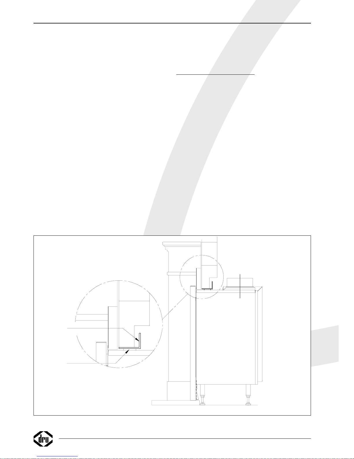
Boezemijzer
38c-1067
fig. 3
Page 7
Nederlands
Plaatsen van het toestel
Het toestel is ontworpen om in te bouwen in een nieuwe
schouw van onbrandbaar en hittebestendig materiaal.
Let op dat er voldoende ruimte is voor de diepte van het
toestel (400 mm) en construeer nauwkeurig i.v.m. de
smalle flens op het binnenwerk.Voor de inbouwmaten
van het toestel, zie figuur 1 en 2.
Let op: het toestel is niet geschikt voor strakke inbouw.
Plaatsen van het toestel in een nieuwe schouw
Plaats het toestel op goede hoogte. De hoogte van het
toestel kan ingesteld worden met de stelpoten. Sluit het
toestel aan en bouw de schouw verder af.
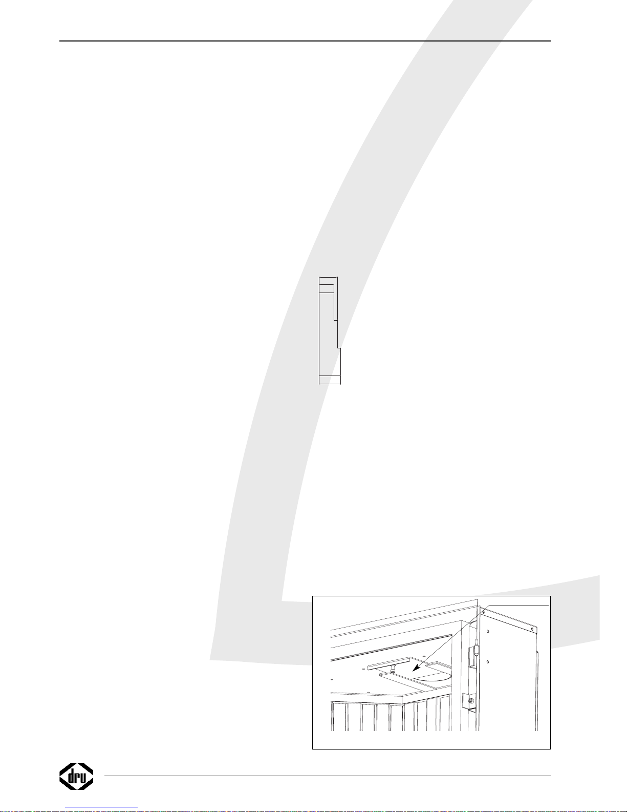
Boezemijzer
Een L-vormige boezemijzer is bij uw installateur te
bestellen. Het boezemijzer dient ervoor het metselwerk
boven de inbouwhaard te ondersteunen. Het toestel kan
hierdoor spanningsvrij worden geïnstalleerd. Plaats het
boezemijzer volgens figuur 3. Houdt een afstand aan van 5
mm tussen de bovenkant van het toestel en de onderkant
van het boezemijzer, zodat het bijgeleverde pakkingkoord
goed afsluit. Let op dat de voorkant van het toestel
(zonder front) en de voorkant van het boezemijzer in
hetzelfde vlak liggen. Door het plaatsen van het front zal
het boezemijzer niet meer zichtbaar zijn.
Aansluiting voor convectielucht
In figuur 1 en 2 is tevens de eventuele convectieluchtaansluiting te zien.
Is een verspreiding van de convectielucht gewenst kan
door middel van flexibele buizen de warmte in diverse
hoeken van het vertrek gebracht worden. Deze aansluit
materialen zijn afzonderlijk te bestellen bij uw leverancier.
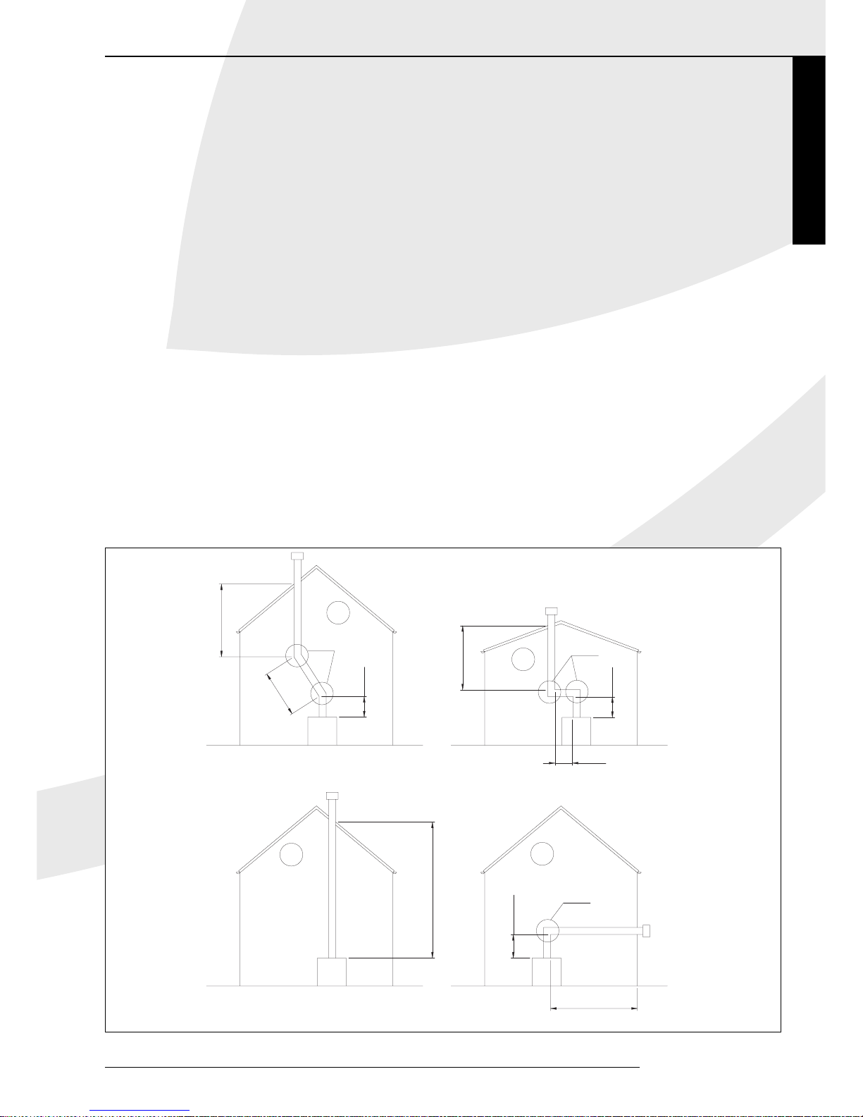
Aansluitmogelijkheden (fig. 4)
De doorvoer naar buiten kan zowel door de gevel als
door het dakvlak plaatsvinden, het aansluiten van de
aan- en afvoerpijpen dient aan onderstaande voorwaarden
te voldoen:
• altijd eerst 1 meter pijp verticaal plaatsen, behalve fig. 4,
voorbeeld 4.
•
de horizontale pijplengte mag nooit langer zijn dan 3 meter
en een muurdoorvoer.
• de maximale pijplengte is 12 meter.
Reken voor een 90° bocht 2 meter en voor een 45°
bocht 1 meter. De lengte van de gevel- of dakdoorvoer
hoeft niet te worden meegerekend.
De maximale totale lengte is de som van de buislengte
plus de vervangende lengte voor de bochten (zie de 4
voorbeelden in fig. 4).
De dakdoorvoerset, luchtaanvoer / rookgasafvoer, de
concentrische pijp en bochten worden per stuk verpakt
en compleet geleverd met een klemband voorzien van
afdichtring.Tevens is een pan- of plakplaat verkrijgbaar
voor doorvoer door resp. een schuin of een plat dak.
Estate / Castello
INSTALLATIEVOORSCHRIFT
3
5m
4m
12
1m
1m
2m
1m
max 3m
1,4m
2x45º
2x90º
L=1+1+4+(2x2)=10
(H totaal= 5m)
L=1+2+5+(2x1)=10
1
2
3
1x90º
L=3+1,4+(2)=6,4
4
38c-744c
fig. 4
Page 8
Let op: Dit toestel mag uitsluitend met het door DRU
geleverde afvoermateriaal ø150/ø80 geïnstalleerd worden.
Dit is samen met het toestel gekeurd en voldoet hiermee
aan alle eisen.Voor afwijkend installatiemateriaal kan DRU
de goede en veilige werking niet garanderen
Voorbereidingen voor het plaatsen van het
in- en uitlaatsysteem
• Maak een keuze uit de aansluitmogelijkheden volgens fig. 4.
• Bouw de concentrische pijpen op vanaf het toestel.Als
door bouwkundige omstandigheden eerst een gedeelte
van het concentrische pijpensysteem wordt ingebouwd let
dan speciaal op de juiste montagewijze.
• Het toestel begint met een contradeel. Hierop de eerste
meter pijp plaatsen. Bij een goede montage is van bovenaf
gezien de blauwe rubber afdichtring in de pijp te zien.
• Houdt een minimale afstand aan van 5 centimeter tussen
de buitenkant van de concentrische pijpen en wand of
plafond.
Geveldoorvoer met concentrische pijpen
Let op dat bij de geveldoorvoer eerst 1,4 meter pijp
verticaal gemonteerd moet worden.
• Bepaal de plaats van het toestel en van de plaats van de
geveldoorvoer.
• Maak op de plaats van de geveldoorvoer een gat van
Ø160 mm.
• Sluit nu één of meerdere concentrische pijpen verticaal
aan op de uitmonding van het toestel. Druk deze aan en
breng de klemband(en) aan. De blauwe rubber ring zorgt
voor voldoende afdichting van het verbrandingsgas
afvoersysteem.
• Plaats hierop de bocht en eventuele horizontale
concentrische pijpen en maak deze ook gasdicht.
• Sluit de geveldoorvoer aan op de bocht of horizontale
pijplengte en zorg dat deze ook gasdicht wordt afgesloten.
Dakdoorvoer met concentrische pijpen
Een dakdoorvoer kan op elk punt van het dak uitmonden,
eventueel met een versleping naar de nok. De
dakdoorvoer wordt afhankelijk van één van bovenstaande
mogelijkheden geleverd met een plakplaat voor een plat
dak of een universeel verstelbare pan voor een schuin dak.
• Bepaal de plaats van het toestel en van de plaats van de
dakdoorvoer.
• Maak op de plaats van de dakdoorvoer een gat van Ø160
mm.
• Sluit nu de concentrische pijpen verticaal aan op de
uitmonding van het toestel. Druk deze aan en breng de
klemband aan. De blauwe rubber ring zorgt voor
voldoende afdichting van het verbrandingsgas
afvoersysteem.
• Bepaal de lengte van de benodigde pijpen en zorg ervoor
dat de plakplaat of de universele pan goed aansluit op het
dak.
• Zaag de buitenpijp af op de juiste lengte.
• Sluit de dakdoorvoer aan op de concentrische pijpen.
Let op: u kunt ook eerst de concentrische pijpen
aanbrengen alvorens het toestel te plaatsen. U dient dan
de aansluiting op de uitmonding van het toestel te maken
met een inkortbare pijp.
Bestaande schoorsteen
Het is ook mogelijk om de het toestel op een bestaande
schoorsteen aan te sluiten. Hiervoor wordt door DRU een
speciale schoorsteen aansluitset geleverd. Daarin vindt u
ook een installatievoorschrift voor deze aansluitset.
Bij aansluiting op een bestaande schoorsteen moeten
gelden de volgende punten:
• De schoorsteen moet minimaal ø 150mm zijn.
• De totale lengte mag niet meer zijn dan 12 m en niet
meer dan 4 m horizontaal.
• De schoorsteen dient voor de installatie goed gereinigd te
worden.
Instellingen restrictieschuif
Om een goede werking van het toestel te
waarborgen dient men enkele handelingen
te verrichten zodat het toestel optimaal wordt
afgesteld op het klantspecifieke pijpensysteem.
Bij dakdoorvoer:
Restrictieschuif instellen.
De restrictieschuif wordt los meegeleverd en moet in het
toestel worden geplaatst zoals aangegeven in fig.6.
Met behulp van de bijgeleverde afstelmal (fig. 5) kan de
schuif op de juiste maat afgesteld worden. Na het afstellen
kan de restrictieschuif vastgezet worden met de inbusbout.
De te verrichten handelingen zijn:
• Restrictieschuif instellen bij de berekende totale lengte van
het pijpensysteem 1 tot 12 m, (plaatje 1,2 & 3).
1 tot 3 m: restrictieschuif op 33 mm
4 tot 8 m: restrictieschuif op 27 mm
9 tot 12 m: restrictieschuif op 23 mm
Schuif de restrictieschuif in totdat deze niet verder kan, de
opening is dan automatisch 23 mm.
Let op: De maximale verticale pijplengte is 12 meter.
4
INSTALLATIEVOORSCHRIFT
38c-1068
39
27
33
fig. 5
3
8
C
-972
fig. 6
Restrictieschuif
Page 9
Nederlands
Estate / Castello
5
Bij geveldoorvoer:
Bij onderstaande toepassingen, zijn de te verrichten
handelingen:
• 1,4 meter pijp verticaal, een bocht van 90° en een
muurdoorvoer
Restrictieschuif op 39 mm
• 1,4 meter pijp verticaal, een bocht van 90° en max 3
meter horizontaal en een muurdoorvoer.
Geen restrictieschuif
Let op dat de maximale horizontale lengte niet
wordt overschreden.
In figuur 4 is geïllustreerd hoe de totale lengten moeten
worden berekend.
Aansluiting van de gastoevoer
Het toestel wordt standaard geleverd met een 40 cm
lange flexibele RVS gasaansluiting met nippel G3/8" om
een snelle en eenvoudige installatie mogelijk te maken.
Gebruik in de toevoerleiding een gekeurde aansluitkraan
met koppeling (voor België moet deze B.G.V. gekeurd
zijn).Verder geldt:
• Ontlucht de toevoerleiding voordat het toestel wordt
vastgekoppeld.
• De bedieningskraan mag niet verdraaid worden bij het
aansluiten aan de gastoevoerleiding.
• Vermijd spanningen op de bedieningskraan en leidingen.
• Controleer de aansluitingen op gasdichtheid.
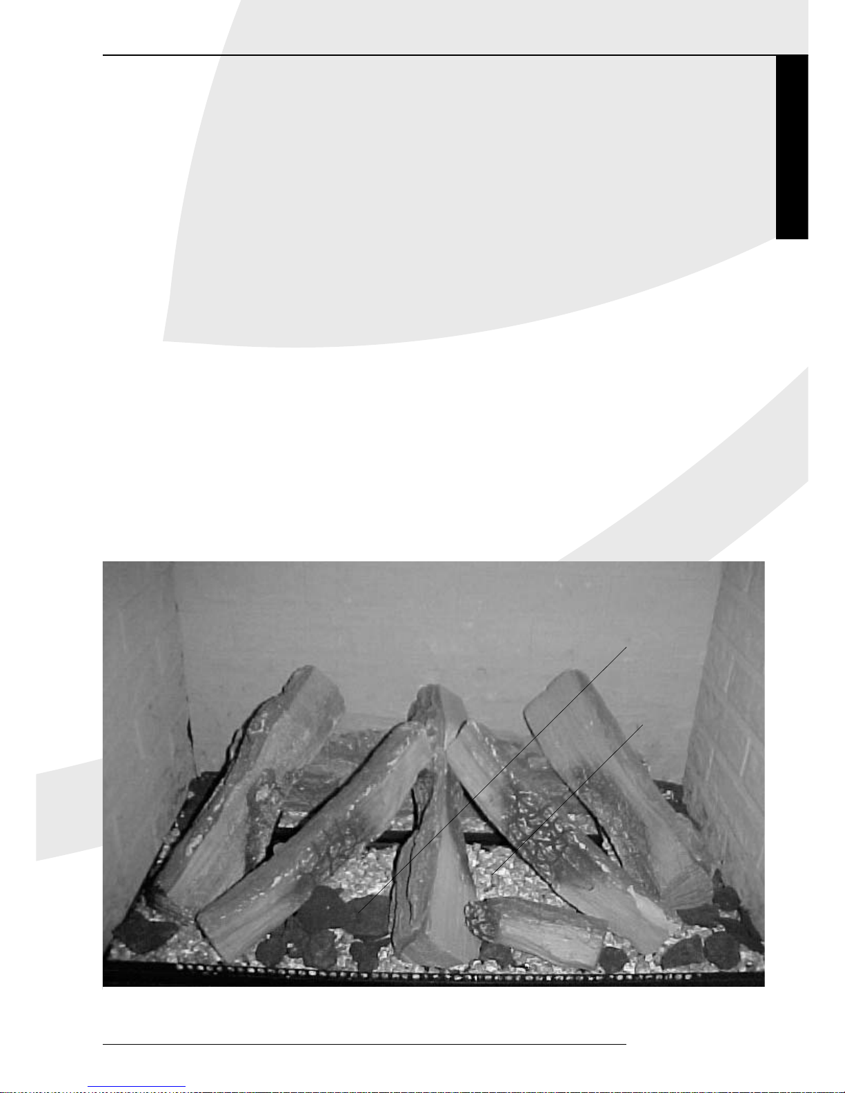
Plaatsen van de houtblokken
Plaats de houtblokken als volgt:
• Leg het grote blok tegen de achterwand.
• Vul de brander met vermiculiet.
• Verdeel het gelijkmatig over de branderbak (een dun
laagje) en de bak eromheen.
• Let op dat er geen vermiculiet op of tussen de
waakvlambrander komt, dit kan de goede werking van de
waakvlam verstoren.
• Verdeel bovenop het vermiculiet, op de bak om de
branderbak heen, de chips.
Geen chips op de branderbak leggen.
• Plaats vervolgens de overige blokken zoals in fig. 7 is
aangegeven.
De blokken mogen niet op een andere manier neergelegd
worden, omdat dan roetvorming kan ontstaan, ook mogen
de blokken niet tegen de waakvlambrander aan liggen.
Gebruik geen andere materialen dan die meegeleverd zijn.
De meegeleverde materialen zijn onbrandbaar en speciaal
voor dit toestel gemaakt.
Glasraam monteren
Na het plaatsen van de houtblokken kan het glasraam
weer gemonteerd worden.
Dit doet men door de ruit in de rand onder te plaatsen
en boven aan vast te zetten met de klemstrip.
Let op dat bij beschadiging of breuk het raam direct
wordt vervangen.
INSTALLATIEVOORSCHRIFT
fig. 7
Chips
Vermiculiet
Page 10
6
INSTALLATIEVOORSCHRIFT GEBRUIKERSHANDLEIDING
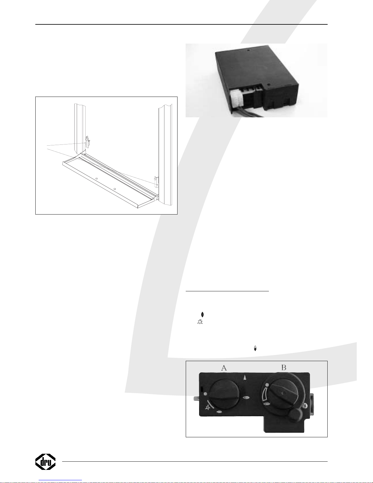
Frontpaneel monteren (fig. 8)
Het frontpaneel wordt los van de basisset verpakt.
Het plaatsen gebeurt op de volgende manier.
Hang het frontpaneel met de haken aan de
verbrandingskamer.
Druk de klep open en draai de schroeven in de daarvoor
bestemde gaten.
Draadloze bediening
De haard wordt standaard geleverd met een draadloze
bediening. Het toestel is voorzien van een traploos
regelbaar gasregelblok. De elektrische voeding wordt
verzorgd door batterijen. De levensduur van de batterijen
is ongeveer één jaar. De draadloze bediening werkt alleen
wanneer de waakvlambrander is ontstoken.
Aansluiten van de ontvanger
De draadloze bediening bestaat uit een ontvanger en een
afstandsbediening. Deze zijn samen verpakt in een doos.
De ontvanger moet worden aangesloten in het toestel
voordat de batterijen worden gemonteerd.
Ga hiervoor als volgt te werk:
• Neem de ontvanger uit de verpakking.
• Schuif de witte stekker van het aansluitsnoer achterop de
printplaat van de ontvanger (fig. 9).
• Sluit de snoeren aan op de connectoren van het
gasregelblok. De stekkers hebben verschillende maten en
corresponderen met de connectoren op het gasregelblok.
• Neem de deksel los.
• Plaats de 4 penlite batterijen (type AA). Let op de juiste
poolrichtingen.
• Plaats de deksel terug.
• Leg de ontvanger onder het toestel op de grond. Zorg
ervoor dat de rode LED naar voren wijst. Leg de
ontvanger, als het kan, zo ver mogelijk van de branderbak
zodat de ontvanger niet te warm kan worden.
Vervangen van de batterijen in de ontvanger
• Open de klep aan de voorzijde.
• Pak de ontvanger en open de deksel.
Achter deze deksel bevindt zich de batterijhouder.
• Verwijder de oude batterijen en plaats de nieuwe, let
daarbij op de + en – aansluiting van de batterijen en de
houder; deze moeten overeenkomen.
Plaatsen of vervangen van de batterijen in de
afstandsbediening
• Verwijder de deksel aan de onderzijde van de
afstandsbediening.
• Sluit de blokbatterij (type 6LR61) aan op de clip.
• Plaats de batterij in de houder.
• Sluit de deksel.
• In het display staat de temperatuur aangegeven in
Fahrenheit, door beide knoppen enkele seconden
ingedrukt te houden, verandert dit in Celsius.
Let op: oude batterijen mogen niet bij het huisvuil maar
moeten bij het Klein Chemisch Afval.
GEBRUIKERSHANDLEIDING
Aansteken
Knop A in drukken en linksom draaien tot de kleine
vlam .
Bij zal het toestel ontsteken. Controleer of de
waakvlam brandt. Indien de waakvlam brandt, knop A nog
ca. 5 sec. geheel ingedrukt houden. Daarnaknop A loslaten
en controleren of de waakvlam blijft branden. Draai nu
knop A naar de grote vlam . Hierdoor zal de hoofdklep
fig. 10
38c-1069
Schroeven
plaatsen
voor
montage
van
het
front
fig. 8
fig. 9
Page 11
van het regelblok opengaan.Afhankelijk van de stand van
de regelknop B zal de hoofdbrander door de waakvlam
ontstoken worden en zullen hogere of lagere vlammen te
zien zijn.
Afstandsbediening
Met de afstandsbediening kan de vlamhoogte worden
geregeld. Knop B (fig. 10) op het gasregelblok zal hierdoor
draaien. Door op de onderste knop van de
afstandsbediening te drukken zal de vlam kleiner worden,
drukt u op de bovenste knop dan zal de vlam hoger
worden. Indien knop B met de hand bediend wordt zal
hetzelfde resultaat worden bereikt. Het verdraaien van
knop B moet met enige kracht gebeuren, het klinken van
tikken is hierbij volstrekt normaal.
Waakvlamstand
Wanneer het toestel niet gebruikt wordt maar wel de
waakvlam moet branden kan knop A naar de kleine vlam
worden gedraaid. Hierdoor wordt de gastoevoer naar de
hoofdbrander afgesloten
Uitschakelen
Draai knop A rechtsom naar de "0" stand. De gastoevoer
naar de hoofd- en de waakvlambrander is dan gesloten.
Belangrijk
Een ingebouwde veiligheidsvergrendeling treedt in werking
wanneer het toestel op de "0" stand (gesloten stand)
wordt gezet.Wacht daarom 5 minuten alvorens het toestel
opnieuw te ontsteken. Probeer binnen deze tijd niet de
aansteekknop in te drukken, daar deze door de veiligheids
vergrendeling geblokkeerd is. Forceer de knop niet, omdat
het mechanisme dan kan worden beschadigd.
ALGEMENE OPMERKINGEN
Onderhoud en reiniging
Periodiek onderhoud dient door een bevoegd installateur
te worden uitgevoerd. Het verdient aanbeveling om vóór
en tijdens het stookseizoen het toestel enkele malen
stofvrij te maken. Op de binnenkant van het glasraam kan
zich na verloop van tijd aanslag vormen, welke u kunt
verwijderen met een vochtige doek of met een niet
krassend reinigingsmiddel (zoals koperpoets). Bij het
reinigen van de mantel geen bijtende of schurende
middelen gebruiken. Lakbeschadigingen, bijvoorbeeld door
het plaatsen van voorwerpen op of tegen de mantel, vallen
buiten de garantie.
Let op: Bij het vervangen van het thermo-element moet
de wartel in het gasregelblok handvast gedraaid worden,
waarna deze met een steeksleutel een kwartslag
aangedraaid moet worden.
Verkleuring van wanden en plafonds
Bruinverkleuring is een vervelend probleem en is moeilijk
op te lossen. Bruinverkleuring kan worden veroorzaakt
door onder andere stofverbranding veroorzaakt door te
weinig ventilatie, door het roken van sigaretten of het
branden van kaarsen.
Deze problemen kunnen worden voorkomen door:
Het vertrek waar het toestel zich bevind goed te
ventileren. Een goede richtlijn hiervoor is
Bij nieuwbouw : 3.24 m
3
/ uur per m
2
vloeroppervlak van een vertrek.
Bij bestaande bouw : 25.20 m
3
/ uur voor een vertrek.
Maak zo weinig mogelijk gebruik van kaarsen en
olielampjes en houd het verbrandingslontje zo kort
mogelijk. Deze "sfeerbrengers" zorgen voor aanzienlijke
hoeveelheden vervuilde en ongezonde roetdeeltjes in uw
woning. Rook van sigaretten en sigaren bevat o.a.
teerstoffen die bij verhitting eveneens op koudere en
vochtige muren zullen neerslaan. Bij een nieuw gemetselde
schouw of na een verbouwing wordt aanbevolen minimaal
6 weken te wachten voordat men gaat stoken, het
bouwvocht moet namelijk geheel verdwenen zijn uit
wanden, vloer en plafond.
Nederlands
GEBRUIKERSHANDLEIDING ALGEMENE OPMERKINGEN
✂
REGISTRATIEKAART
DRU Verwarming kan alleen garantie verlenen indien deze registratiekaart volledig en duidelijk
in blokletters en binnen 5 dagen opgestuurd is aan DRU Verwarming B.V.
Type: . . . . . . . . . . . . . . . . . . . . . . . . . . . . . . . . . . . . Aankoopdatum: . . . . . . . . . . . . . . . . . . . . . . . . . . . . . . .
Kleur: . . . . . . . . . . . . . . . . . . . . . . . . . . . . . . . . . . . Serienummer (op typeplaat): . . . . . . . . . . . . . . . . . . . . .
Koper: Detaillist/installateur:
Naam . . . . . . . . . . . . . . . . . . . . . . . . . . . . . . . . . . . Naam . . . . . . . . . . . . . . . . . . . . . . . . . . . . . . . . . . . . . . .
Adres . . . . . . . . . . . . . . . . . . . . . . . . . . . . . . . . . . . Adres . . . . . . . . . . . . . . . . . . . . . . . . . . . . . . . . . . . . . . .
Postcode . . . . . . . . . . . . . . . . . . . . . . . . . . . . . . . . . Postcode . . . . . . . . . . . . . . . . . . . . . . . . . . . . . . . . . . . .
Plaats . . . . . . . . . . . . . . . . . . . . . . . . . . . . . . . . . . . . Plaats . . . . . . . . . . . . . . . . . . . . . . . . . . . . . . . . . . . . . . .
Telefoon . . . . . . . . . . . . . . . . . . . . . . . . . . . . . . . . . Telefoon . . . . . . . . . . . . . . . . . . . . . . . . . . . . . . . . . . . . .
Hartelijk dank voor uw medewerking.
Page 12
Eerste maal stoken
Tijdens de eerste maal stoken kan er een onaangename
geur ontstaan, die wordt veroorzaakt door het uitdampen
van de lak. Dit verdwijnt na enkele uren. Daarom raden wij
u aan het toestel de eerste maal op de hoogste stand te
stoken terwijl u tevens het vertrek waarin de kachel staat
goed ventileert.
Extra bescherming
Indien het toestel in een vertrek geïnstalleerd wordt waar
jonge kinderen of hulpbehoevende mensen zonder toezicht
verblijven, is het wenselijk het toestel af te schermen.
Afdanken
Indien u het toestel vervangt of verwijdert, moet u het
toestel via de reguliere weg afvoeren.Voordat tot
demontage wordt overgegaan eerst de aansluitkraan met
koppeling dichtdraaien. De koppeling tussen aansluitkraan
en toestel losdraaien. Het gehele toestel kan nu worden
gedemonteerd en afgevoerd.
Garantie
De REGISTRATIEKAART gelieve binnen 5 dagen na
aankoop in te vullen en op te sturen in een envelop
zonder postzegel naar het onderstaande adres.
DRU VERWARMING B.V.
ANTWOORDNUMMER 4551
6920 ZX DUIVEN
Het GARANTIEBEWIJS (blz. 1) kunt u zelf behouden.
De garantie gaat in op het ogenblik, dat de volledig
ingevulde registratiekaart door DRU Verwarming is
ontvangen.
VOOR BELGIË DE
KAART INVULLEN OP PAGINA 25 EN 31.
✂
VERSTUREN IN EEN
ENVELOP
NAAR
DRU VERWARMING B.V.
ANTWOORDNUMMER 4551
6920 ZX DUIVEN
Page 13

English
Estate / Castello
9
CONTENTS
CONTENTS
Foreword . . . . . . . . . . . . . . . . . . . . . . . . . . . . . . . .10
Unpacking . . . . . . . . . . . . . . . . . . . . . . . . . . . . . . . .10
Connection . . . . . . . . . . . . . . . . . . . . . . . . . . . . . . .10
Instructions for installation . . . . . . . . . . . . . . . . . . .10
Type of gas . . . . . . . . . . . . . . . . . . . . . . . . . . . . . . .10
Important . . . . . . . . . . . . . . . . . . . . . . . . . . . . . . . .10
Positioning the appliance . . . . . . . . . . . . . . . . . . . . .10
Mantel iron . . . . . . . . . . . . . . . . . . . . . . . . . . . . . . .11
Convection connection . . . . . . . . . . . . . . . . . . . . .11
Possible connections . . . . . . . . . . . . . . . . . . . . . . . .11
Preparations for the installation
of the combined inlet-outlet system . . . . . . . . . . . .11
Wall duct with concentric pipes . . . . . . . . . . . . . . .12
Roof duct with concentric pipes . . . . . . . . . . . . . . .12
Fitting the fire to an existing chimney . . . . . . . . . . .12
Baffle . . . . . . . . . . . . . . . . . . . . . . . . . . . . . . . . . . . .12
Using a roof duct . . . . . . . . . . . . . . . . . . . . . . . . . .12
Using a wall duct . . . . . . . . . . . . . . . . . . . . . . . . . .12
Connecting the Gas Supply . . . . . . . . . . . . . . . . . . .13
Positioning the logs . . . . . . . . . . . . . . . . . . . . . . . . .13
Fitting the glass panel . . . . . . . . . . . . . . . . . . . . . . .13
Fitting the front panel . . . . . . . . . . . . . . . . . . . . . . .14
Remote control . . . . . . . . . . . . . . . . . . . . . . . . . . .14
Connecting the Receiver . . . . . . . . . . . . . . . . . . . . .14
Replacing the batteries in the receiver . . . . . . . . . .14
Inserting or replacing the batteries in the
remote control . . . . . . . . . . . . . . . . . . . . . . . . . . . . . . . . . .14
Operating Instructions . . . . . . . . . . . . . . . . . . . . . .14
Lighting . . . . . . . . . . . . . . . . . . . . . . . . . . . . . . . . . .14
Remote Control . . . . . . . . . . . . . . . . . . . . . . . . . . .15
Pilot light setting . . . . . . . . . . . . . . . . . . . . . . . . . . .15
Switching off . . . . . . . . . . . . . . . . . . . . . . . . . . . . . .15
Important . . . . . . . . . . . . . . . . . . . . . . . . . . . . . . . .15
General notes . . . . . . . . . . . . . . . . . . . . . . . . . . . . .15
Gas safety regulations (for installation & use), 1998 15
Cleaning and Maintenance . . . . . . . . . . . . . . . . . . .15
Discoloration of walls and ceiling . . . . . . . . . . . . . .15
Lighting the heater for the first time . . . . . . . . . . . .16
Extra protection . . . . . . . . . . . . . . . . . . . . . . . . . . .16
Disposal . . . . . . . . . . . . . . . . . . . . . . . . . . . . . . . . .16
Guarantee . . . . . . . . . . . . . . . . . . . . . . . . . . . . . . . .16
Technical specifications . . . . . . . . . . . . . . . . . . . . . .35
Conditions of warranty
• This appliance has been manufactured and tested by DRU verwarming BV of The Netherlands with utmost care.
• Subject to the conditions set out on this card DRU guarantees the proper operation of this vented room heater to the original purchaser for a period of
one year after date of purchase.
• Subject to the conditions set out on this card, the cast iron combustion chamber of your DRU vented room heater carries a full guarantee to the original
purchaser for a period of ten years after date of purchase.
• The guarantee does not cover the normal wear and tear, damage due to incorrect treatment, changes of the equipment or unauthorised installations and
repairs. No liability is assumed by DRU for removal or (re)installation labor costs.
• Under no circumstances shall DRU be liable for incidental,consequential, special or contingent damages or expenses arising directly or indirectly from any
defect in the product or any component or from the use thereof.The remedies set forth herein are the exclusive remedies available to the user and are in
lieu of all other remedies. Subject to specific state laws some of the above limitations or exclusions may not apply to you.
DRU Verwarming B.V.
WARRANTY CARD
Please complete this card and keep it with the invoice to verify purchase date
and to establish the warranty period*.
Model: . . . . . . . . . . . . . . . . . . . . . . . . . . . . . . . . Date: . . . . . . . . . . . . . . . . . . . . . . . . . . . . . . . . . .
Colour: . . . . . . . . . . . . . . . . . . . . . . . . . . . . . . . Serial No.: . . . . . . . . . . . . . . . . . . . . . . . . . . . . . .
Type of Gas: Natural Gas ❑ L.P.G.❑ (please check)
Customer: Dealer/Installer
Name . . . . . . . . . . . . . . . . . . . . . . . . . . . . . . . . . Name . . . . . . . . . . . . . . . . . . . . . . . . . . . . . . . . .
Address . . . . . . . . . . . . . . . . . . . . . . . . . . . . . . . Address . . . . . . . . . . . . . . . . . . . . . . . . . . . . . . . .
City . . . . . . . . . . . . . . . . . . . . . . . . . . . . . . . . . City . . . . . . . . . . . . . . . . . . . . . . . . . . . . . . . . . . .
State . . . . . . . . . . . . . . . . . . . . . . . .ZIP . . . . . State . . . . . . . . . . . . . . . . . . . . . . . . .ZIP . . . . . .
Province . . . . . . . . . . . . . . . . . . . . . .P.C. . . . . . Province . . . . . . . . . . . . . . . . . . . . . .P.C. . . . . . .
Telephone ( . . . . . . . . .) . . . . . . . . . . . . . . . . . .
*FOR SERVICE UNDER THIS WARRANTY CONTACT YOUR DEALER/INSTALLER.
DRU warrants the proper functioning of this vented roomheater if installed by a qualified installer and if used in
strict accordance with the manufacturers operating instructions
Page 14

Foreword
Dear Customer,
We would like to thank you for buying this DRU product.
Our products have been designed and produced to meet
the highest possible quality, performance and safety
requirements, allowing you to enjoy years of problem-free
use.
The heater has an enclosed combustion chamber. Its
natural draught draws in the combustion air from outside
through a combined inlet-outlet system.The same natural
draught expels the combustion gasses.
In this booklet you will find instructions for the installation
and use of your new appliance. Please read these
instructions and the manual carefully to familiarize yourself
with the appliance. If you require any further support,
please do not hesitate to contact your supplier.
Unpacking
When unpacking the interior, be careful not to allow the
box of logs fall out of the combustion chamber.The glass
front is packed separately. Once the heater has been
unpacked, all packaging should be disposed of in the
regular manner.
Connection
This appliance should be connected by a competent person.
INSTRUCTIONS FOR INST
ALLATION
Type of gas
This appliance is suitable for G20 or G25. Please check
that the type of gas and the local pressure correspond
with the specifications on the data badge.All regulations
regarding gas installation, including any local regulations,
must be observed at all times. The appliance is to be
installed by a registered installer.
Important
• Keep curtains and any other flammable materials at least
50cm away form the appliance.
• Caution! Touching the heater when hot can cause burns
and blisters!
• The appliance should be installed and maintained by a
competent person.
• Do not install any so-called dust filter on or under the
casing.
• Do not hang wet clothes and towels etc. on the heater to
dry.
Positioning the appliance
The fire is designed to be built into a new fireplace of
incombustible and heat-resistant material.
Allow enough space for the depth of the appliance (400
mm) and work accurately, allowing for the narrow flange
on the inside. See figs. 1 and 2 for the build-in dimensions.
N.B.: this fire is not suitable for snug, hole-in-the-wall
installation.
10
INSTRUCTIONS FOR INSTALLATION
Packing
70x50x4
Mantel iron
38c-1067
fig. 3
Page 15

English
Estate / Castello
INSTRUCTIONS FOR INSTALLATION
11
Installing the appliance in a new fireplace
Position the fire at the right height. Use the adjustable
feet to adjust the height of the appliance. Connect the fire
and finish the fireplace.
Mantel iron
An L-shaped mantel Iron can be ordered from your
installer.The mantel Iron, intended to support the
brickwork above the fire.This enables a stress-free
installation of the appliance. Fit the mantel iron as
illustrated in fig. 3, allowing 5 mm between the top of the
appliance and the bottom of the mantel iron, so that the
packing cord provided seals adequately. Make sure that
the front of the heater (without the decorative facing)
and the front of the mantel iron are flush.Fitting the
decorative facing will hide the mantel iron from sight.
Convection connection
Figures 1 and 2 also show the possibility of a convectionheat connection.
The convection system of flexible pipes will enable the
heat to be spread to every corner of the room.The
connection materials can be ordered separately from
your dealer.
Possible connections (fig. 4)
The external duct can pass through either the wall or the
roof; the connections to both supply and flue pipes
should meet the following requirements:
• The first metre of pipe should always be fitted vertically,
except example 4 in fig. 4.
• The horizontal length of pipe should never be more than
3 metres and a wall duct.
• The maximum length of vertical pipe is 12 metres.
Allow 2 metres for a bend of 90° and 1 metre for a 45°
bend.There is no need to allow for the length of the wall
or roof duct.
The maximum total length is the sum of the pipe lengths
plus the substitute length for the bends (see the four
examples in fig. 4).
The roof duct set, the supply and flue pipes, the
concentric pipe and bends are packed separately and
supplied together with a clip binding with sealing ring.
Tile flashing or adhesive flashing is also available for use
with a duct through a slanting or flat roof respectively.
NB: This appliance may only be installed using the flue
material ø150/ø80 supplied by DRU.This has been
approved together with the appliance to comply with all
requirements. DRU cannot guarantee that the appliance
will work correctly and safely if alternative installation
material is used.
Preparations for the installation of the
combined inlet-outlet system
• Select the required connection from the options shown
in figure 4.
• Erect the concentric pipes from the heater up. If the
5m
4m
12
1m
1m
2m
1m
max 3m
1,4m
2x45º
2x90º
L=1+1+4+(2x2)=10
(H total= 5m)
L=1+2+5+(2x1)=10
1
2
3
1x90º
L=3+1,4+(2)=6,4
4
38c-744c
fig. 4
Page 16

structural situation requires that the first section of the
concentric pipe system be built in, take special note of
the required method of assembly.
• The appliance has a coupling section; fit the first metre of
pipe onto this. When correctly assembled, the blue
rubber sealing ring inside the pipe should be visible from
the top.
• Allow at least 5 cm between the outside of the
concentric pipes and the wall or ceiling.
Wall duct with concentric pipes
Ensure that the first 1,4 metre of pipe used for the wall
duct is assembled vertically.
• Determine the position of the appliance and the position
of the wall duct.
• Drill a Ø160 mm hole at the point where the wall duct is
required.
• Now vertically connect one or more concentric pipes to
the heater outlet. Press well and fit the strip(s) of clip
binding. The blue rubber ring will sufficiently seal the flue
system.
• Place the bend on top of this, fit any horizontal concentric
pipes required, and make sure the connections are
gastight.
• Connect the wall duct to the bend or the horizontal pipes
and make sure that this connection is also gastight.
Roof duct with concentric pipes
A duct through a roof can open out anywhere on the roof,
with an extension to the ridge if necessary. Depending on
which of the aforementioned options has been chosen, the
roof duct will be supplied with either adhesive flashing for
a flat roof or a universally adjustable tile for a slanted roof.
• Determine the position of the appliance and the position
of the chimney.
• Drill a Ø 160 mm hole at the point where the chimney is
required.
• Now vertically connect the concentric pipes to the
heater outlet. Press well and apply the clip binding. The
blue rubber ring will sufficiently seal the flue system.
• Determine the length of the pipes required and ensure
that the adhesive flashing or the universal tile fit properly.
• Saw the outside pipe off at the length required.
• Connect the roof duct to the concentric pipes.
NB: Alternatively, you can fit the concentric pipes before
installing the heater. In that case the connection to the
outlet of the appliance should be made using a length of
pipe that can be shortened later.
Fitting the fire to an existing chimney
The fire can be fitted into an existing chimney providing
that the chimney / flue dimensions are 150 mm or more.
A special flue kit is required, which can be obtained
from Drugasar or a Drugasar agent. Do not use any
other type of flue system for this.
BS 5871 – 1 : 2001
Any chimney previously used for an appliance burning a
fuel other than gas shall be swept thoroughly before
installing any gas appliance.
Appliances shall be connected only to the types and sizes
of flue system as specified.
For any other information about this flue system please
contact Drugasar or Drugasar approved agent.
Baffle
To ensure that the appliance
works satisfactorily,
it will need to be adjusted
according to the
customer-specific pipe system.
Using a roof duct:
Adjusting the baffle.
The baffle is supplied separately and should be fitted into
the heater as indicated in fig. 6. Use the adjustment jig
provided (fig. 5) to adjust the baffle to the right size. Once
it has been adjusted, fix the damper in place with the
socket-head screw.
• Adjust the baffle according to the calculated total pipe
length of between 1 and 12 m, (figs. 1, 2 & 3), as follows:
1 - 3 m: adjust damper to 33 mm
4 - 8 m: adjust damper to 27 mm
9 - 12 m: adjust damper to 23 mm
Slide the baffle in as far as it will go, the opening will
automatically be 23mm.
NB: The maximum length of vertical pipe is 12 metres.
Using a wall duct:
For the following applications, the adjustments required
are:
• 1,4 metre vertical pipe with a 90° bend and a wall duct:
adjust damper to 39 mm
• 1,4 metre vertical pipe with a 90° bend and max. 3
metres horizontal pipe and a wall duct.
No baffle
12
INSTRUCTIONS FOR INSTALLATION
38c-1068
39
27
33
fig. 5
3
8C
-97
2
fig. 6
Baffle
Page 17

Estate / Castello
13
English
NB: the maximum length of horizontal pipe must
not be exceeded.
Fig. 4 illustrates how to calculate the total lengths of pipe.
Connecting the Gas Supply
With the appliance a 40 cm flexible stainless steel gas
hose with G3/8" nipple joint has been supplied to
facilitate quick and easy installation.An approved
connecting tap with coupling should be used in the supply
hose (In Belgium this must be B.G.V. approved).
Furthermore:
• Expel all air from the supply pipes/hoses before coupling
to the appliance.
• Do not turn the coupling tap when connecting it to the
gas supply.
• Avoid any pressure on the control tap and pipes.
• Check that all connections are gastight.
Positioning the logs
Position the logs as follows:
• Lay the large log against the back wall.
• Fill the burner with vermiculite.
• Spread it evenly (in a thin layer) on the burner tray and
the surrounding tray.
• Make sure that no vermiculite gets on or into the pilot
light burner, as this could prevent it from working
properly.
• Sprinkle the chips on top of the vermiculite, on the tray
surrounding the burner tray.
Do not put any chips on the burner tray.
• Now lay the rest of the logs in place as illustrated in fig. 7.
The logs should not be laid in any other way as this could
cause the formation of soot. Neither should the logs
touch pilot light burner.
Do not use any materials other than those supplied.The
supplied materials are incombustible and have been
manufactured specifically for this appliance.
Fitting the glass panel
Once the logs are in position, the glass can be replaced.
Fit the pane into the edge at the bottom and fix with the
mounting strip at the top.
If the glass is broken or at all damaged it should be
replaced immediately.
INSTRUCTIONS FOR INSTALLATION
fig. 7
Chips
Vermiculite
Page 18

Fitting the Front Panel (fig. 8)
The front panel is packed separately to the basic set, and
fitted as follows.
Hook the front panel onto the combustion chamber.
Push the flap open and fit the screws in the appropriate
hole.
For safety reasons a guard should be placed in front of the
fire at all times.
Remote control
Remote control is supplied as a standard accessory.The
heater has a freely adjustable. Batteries, with a life
expectancy of approximately one year, feed the electrical
supply.The remote control will only work if the pilot light
is lit.
Connecting the Receiver
The remote control system comprises a receiver and a
remote control, packed together in one box. The receiver
must be connected to the appliance fitting the batteries.
This is done as follows:
• Take the receiver out of the box.
• Slide the white plug of the cable onto the receiver circuit
board (fig. 9).
• Connect the wires to the connectors on the gas control
valve.The different sized plugs correspond with the
connectors on the gas control valve.
• Open the lid.
• Insert 4 penlight batteries (type AA). Make sure they are
the right way round.
• Replace the lid.
• Place the receiver under the appliance on the floor. Make
sure that the red LED points forwards. Place the reciever
as far away from the burner tray as possible to prevent the
reciever from getting too hot.
Replacing the batteries in the receiver
• Open the flap at the front.
• Take the receiver and open the cover.
The batteries are under that cover.
• Remove the old batteries and insert the new ones, making
sure that the + and – signs on the batteries correspond
with those in the holder.
Inserting or replacing the batteries
in the remote control
• Remove the cover on the back of the remote control.
• Connect a square battery (type 6LR61) to the clip.
• Fit the battery in the holder.
• Replace the cover.
• The temperature is shown on the display in Fahrenheit,
press both buttons for a few seconds and it will change to
Celsius.
NB: Do not throw old batteries in the dustbin.They
should be treated as Chemical Waste.
OPERA
TING INSTRUCTIONS
Lighting
Press button A and turn to the left to the small flame .
The flame will ignite at . Check that the pilot is alight. If
that is the case, hold button A firmly pressed for another 5
seconds.Then release button A and check that the pilot
light is still burning. Now turn button A to the large
flame , which will open the main valve of the control
block. Depending on the setting of the control button B,
high or low flames will be visible.
14
INSTRUCTIONS FOR INSTALLATION OPERATING INSTRUCTIONS
fig. 10
38c-1069
Fit the
screws
to fix the
front panel.
fig. 8
fig. 9
Page 19

Remote Control
The height of the flames can be regulated by remote
control, which will turn button B (fig. 8) on the gas control
block. Press the bottom button on the remote control for
a smaller flame; press the upper button for a higher flame.
Manually adjusting button B will have the same effect.A
certain force is required when rotating button B, a clicking
sound is quite normal.
Pilot light setting
If the heater is not in use but you would like the pilot light
to remain alight, set button A to the small flame.The gas
supply to the main burner will then be switched off.
Switching off
Turn button A to the "0" setting.The gas supply to the
burners will then be switched off.
Important
A built-in safety lock is activated when the appliance is
switched to the "0" setting (closed down setting).
Therefore, wait 5 minutes before relighting the heater.
Within this period, do not try to push the lighting button,
as this has been blocked by the safety lock. Do not force
the button, as this may result in damage to the mechanism.
GENERAL NOTES
Gas Safety Regulations (for installation & use) 1998
In your own interest and that of safety, it is law that all gas
appliances are installed by competent persons in
accordance with the above regulations. Failure to install
appliances correctly could lead to prosecution.
NB: The Council of Registered Gas Installers,
whose members are identified by the emblem
shown here, are all required to work to the
recognised standards.
Cleaning and Maintenance
Periodical maintenance should be carried out by a
registered installer.You are recommended to free the
heater of dust before and occasionally during the heating
season. In time, a deposit can form on the inside of the
glass that is best removed with a damp cloth and a nonabrasive cleaning agent (such as copper polish). Do not use
abrasives when cleaning the heater. Damage to the casing
varnish, caused by anything being put on the appliance, is
not covered by the guarantee.
NB: When replacing the thermocouple, the coupling nut in
the gas control block should first be tightened by hand and
then tightened a quarter-turn with an
open-ended spanner.
Discoloration of walls and ceiling
Brown discoloration is an annoying problem, which is
difficult to solve. It can be caused by dust burning as a
result of poor ventilation, for example, or by cigarette
smoke or candles.
These problems can be avoided by ensuring that the room
the heater is in is properly ventilated.A good guideline for
ventilation is:
New buildings : 3.24 m
3
/ hour per m2floor
surface of the room.
Existing buildings : 25.20 m3/ hour for a room.
Use candles and oil lamps as little as possible, keeping the
wick as short as possible.While they Enhance the
atmosphere, candles and oil lamps also cause the
formation of large quantities of unhealthy soot particles in
your home. Cigarette and cigar smoke contains tar, which
upon heating will precipitate on cold or damp walls. If you
have a newly cemented chimney or have had any other
reconstructions / renovations done, you are advised to
wait at least 6 weeks before lighting your fire, to allow the
walls, floor and ceiling to dry out completely.
English
OPERATING INSTRUCTIONS GENERAL NOTES
✂
GUARANTEE REGISTRATION CARD
In order to register your guarantee, please complete and return this card(no stamp required)
Details of equipment:
Model: . . . . . . . . . . . . . . . . . . . . . . . . . . . . . . . . . . . Serial No.: . . . . . . . . . . . . . . . . . . . . . . . . . . . . . . . . . . .
Type of gas: Natural Gas ❑ L.P.G.❑ (please tick).
Model an serial no. are to be found on data badge inside heater.
Customer: Installed by:
Name . . . . . . . . . . . . . . . . . . . . . . . . . . . . . . . . . . . Name . . . . . . . . . . . . . . . . . . . . . . . . . . . . . . . . . . . . . . .
Address (of installation) . . . . . . . . . . . . . . . . . . . . . . Address . . . . . . . . . . . . . . . . . . . . . . . . . . . . . . . . . . . . .
Post Code . . . . . . . . . . . . . . . . . . . . . . . . . . . . . . . . Post Code . . . . . . . . . . . . . . . . . . . . . . . . . . . . . . . . . . .
Tel. No. . . . . . . . . . . . . . . . . . . . . . . . . . . . . . . . . . . Tel. No. . . . . . . . . . . . . . . . . . . . . . . . . . . . . . . . . . . . . .
Appliance installed in . . . . . . . . . . .(Office, Church, etc.)
Is appliance replacing alternative fuel: Solid Fuel ❑ Oil ❑ Electricity ❑ (please tick).
If replacing existing balanced flue heater make of original
Date of installation
N.B.Where more than one appliance installed, please complete all cards and return in envelope using freepost address on reserve.
Completion of this card in no way affects your statutory rights
Thank you DRUGASAR LIMITED
Page 20

Lighting the heater for the first time
There can be an unpleasant smell when you light the
heater for the first time.This is caused by the varnish
evaporating and will disappear after a few hours.We
therefore advise you,on initial use, to heat the appliance at
the highest setting while ventilating the room it is installed
in well.
Extra protection
This heater meets the normal safety standards regarding
surface temperatures, but physical contact with heated
surfaces should be avoided where possible. An additional
guard is recommended to protect young children and
elderly, infirmed or handicapped people.
Disposal
When replacing or otherwise removing the appliance, it
should be disposed of in compliance with current
regulations.
Shut off the connecting tap with coupling before
commencing disassembly. Undo the coupling between the
connecting tap and the appliance.The whole appliance can
now be disassembled and removed.
Guarantee
Please complete the enclosed REGISTRATION CARD and
post it in an envelope (no stamp required) to the address
below within 5 days of purchase.
DRUGASAR LIMITED
FREEPOST
DEANS ROAD
SWINTON
MANCHESTER M27 1 BX
Please retain the GUARANTEE CARD (page 9) for your
own reference.The guarantee will become effective upon
receipt by DRUGASAR Limited of the fully completed
registration card.
GENERAL NOTES
✂
PLEASE SEND IN AN
ENVELOPE
TO
DRUGASAR LIMITED
FREEPOST
DEANS ROAD
SWINTON
MANCHESTER M27 1 BX
DRUGASAR, GAS HEATING FOR PEOPLE WHO DON’T HAVE MONEY TO BURN.
Page 21

Deutsch
Estate / Castello
17
INHALT
Einige kurze Worte . . . . . . . . . . . . . . . . . . . . . . . . .18
Auspacken . . . . . . . . . . . . . . . . . . . . . . . . . . . . . . .18
Anschluss . . . . . . . . . . . . . . . . . . . . . . . . . . . . . . . .18
Installationsvorschrift . . . . . . . . . . . . . . . . . . . . . . .18
Gassorte . . . . . . . . . . . . . . . . . . . . . . . . . . . . . . . . .18
Wichtig . . . . . . . . . . . . . . . . . . . . . . . . . . . . . . . . . .18
Aufstellen des Gerätes . . . . . . . . . . . . . . . . . . . . . .19
Aufstellen des Gerätes in einen neuen Kaminumbau 19
Kaminüberbaueisen . . . . . . . . . . . . . . . . . . . . . . . . .19
Anschluß für Konvektionsluft . . . . . . . . . . . . . . . . .19
Anschlußmöglichkeiten . . . . . . . . . . . . . . . . . . . . . .19
Vorbereitung für den Einbau des
Zu- und Abluftsystems . . . . . . . . . . . . . . . . . . . . . .20
Aussenwanddurchführung mit
konzentrischen Rohren . . . . . . . . . . . . . . . . . . . . . .20
Dachdurchführung mit konzentrischen Rohren . . . .20
Bestehender Schornstein . . . . . . . . . . . . . . . . . . . .20
Restriktionsschieber . . . . . . . . . . . . . . . . . . . . . . . .20
Bei der Dachdurchfuhr . . . . . . . . . . . . . . . . . . . . . .21
Bei Giebeldurchfuhr . . . . . . . . . . . . . . . . . . . . . . . .21
Anschluß der Gaszufuhr . . . . . . . . . . . . . . . . . . . . .21
Einlegen der Holzblöcke . . . . . . . . . . . . . . . . . . . . .22
Glasfenster montieren . . . . . . . . . . . . . . . . . . . . . .22
Frontpaneel montieren . . . . . . . . . . . . . . . . . . . . . .22
Drahtlose Bedienung . . . . . . . . . . . . . . . . . . . . . . . .23
Anschliessen des Empfängers . . . . . . . . . . . . . . . . .23
Ersetzen der Batterien im Empfänger . . . . . . . . . . .23
Einlegen oder Ersetzen der
Batterien in der Fernbedienung . . . . . . . . . . . . . . . .23
Gebrauchsanweisung . . . . . . . . . . . . . . . . . . . . . . . .24
Zünden . . . . . . . . . . . . . . . . . . . . . . . . . . . . . . . . . .24
Fernbedienung . . . . . . . . . . . . . . . . . . . . . . . . . . . .24
Zündflammenstand . . . . . . . . . . . . . . . . . . . . . . . . .24
Ausschalten . . . . . . . . . . . . . . . . . . . . . . . . . . . . . . .24
Wichtig . . . . . . . . . . . . . . . . . . . . . . . . . . . . . . . . . .24
Allgemeine Bemerkungen . . . . . . . . . . . . . . . . . . . .25
Wartung und Reinigung . . . . . . . . . . . . . . . . . . . . .25
Verfärbung von Wänden und Decken . . . . . . . . . . .25
Zum ersten Mal heizen . . . . . . . . . . . . . . . . . . . . . .25
Extra Schutz . . . . . . . . . . . . . . . . . . . . . . . . . . . . . .25
Entsorgen . . . . . . . . . . . . . . . . . . . . . . . . . . . . . . . .25
Garantie . . . . . . . . . . . . . . . . . . . . . . . . . . . . . . . . .25
Technische Spezifikation . . . . . . . . . . . . . . . . . . . . .35
INHALT
GARANTIEERKLÄR
UNG
Bitte vollständig ausfüllen und zusammen
mit Ihrer Einkaufsrechnung aufbewaren. (Blockschrift)
Type: . . . . . . . . . . . . . . . . . . . . . . . . . . . . . . . . . Kaufdatum: . . . . . . . . . . . . . . . . . . . . . . . . . . . . .
Farbe: . . . . . . . . . . . . . . . . . . . . . . . . . . . . . . . . .
Kaufer: Händler:
Name . . . . . . . . . . . . . . . . . . . . . . . . . . . . . . . . . Name . . . . . . . . . . . . . . . . . . . . . . . . . . . . . . . . .
Straße . . . . . . . . . . . . . . . . . . . . . . . . . . . . . . . . Straße . . . . . . . . . . . . . . . . . . . . . . . . . . . . . . . . .
PLZ. und Ort . . . . . . . . . . . . . . . . . . . . . . . . . . . PLZ. und Ort . . . . . . . . . . . . . . . . . . . . . . . . . . . .
BEI STÖR
UNGEN WENDEN SIE SICH BITTE ZUERST AN IHREN LIEFERANTEN.
DRU Verwarming garantiert die gute Wirkungsweise des Gerätes bei fachgerechter Installation
und Gebrauch lt. Gebrauchsanweisungen.
Garantiebestimmungen
• DRU Verwarming B.V. garantiert die Haltbarkeit des Gerätes durch Verwendung von hochwertigem Material.
• Die Garantie ist gültig für 1 Jahr ab Kaufdatum.
• Eingeschlossen sind alle Schäden am Gerät, die eine Folge von Fehlern in der Konstruktion oder für die Konstruktion benötigten Teile sind.
• DRU Verwarming verpflichtet sich,während der Garantiezeit beschädigte Teile kostenlos zu ersetzen oder auszutauschen.
• Die Garantieleistung verfällt, wenn Schäden als Folge von unsachgemäßer Nutzung entstehen, wenn das Gerät fehlerhaft aufgestellt wurde, wenn Unbefugte
Reparaturen ausführen oder wenn am Gerät keine Originalteile verwendet werden
• Die Garantie gilt nicht für Scheiben und Keramik.
DRU Verwarming B.V.
Page 22

Einige kurze Worte
Sehr geehrter Kunde,
Herzlichen Dank für den Kauf dieses DRU Produktes.
Unsere Produkte sind nach den höchst möglichen
Qualitäts- Leistungs- und Sicherheitsanforderungen
entwickelt und fabriziert. Hierdurch haben Sie jahrelanges,
problemloses Gebrauchsvergnügen.
Das Gerat verfügt über eine geschlossene
Verbrennungskammer. Die Verbrennungsluft wird mit
einem kombinierten Ein- und Auslass von aussen durch
den natürlichen Zug des Gerätes angezogen. Durch
denselben natürlichen Zug werden die Verbrennungsgase
abgeleitet.
In diesem Buch finden Sie Instruktionen zur Installation
und zum Gebrauch Ihres neuen Gerät. Lesen Sie die
Instruktionen und die Gebrauchsanleitung gut nach, so daß
Sie sich mit dem Gerät vertraut machen können. Möchten
Sie mehr Unterstützung haben, nehmen Sie dann Kontakt
mit Ihrem Lieferanten auf.
Auspacken
Achten Sie beim Auspacken des Innenwerks darauf, dass
der Karton mit den Holzblöcken nicht aus der
Verbrennungskammer fällt. Das Fenster ist gesondert
verpackt. Nach dem Auspacken muss die Verpackung auf
dem regulären Weg entsorgt werden.
Anschluss
Dieses Gerät muß von einem zugelassenen Installateur
angeschlossen werden.
INSTALLATIONSVORSCHRIFT
Gassorte
Dieses Gerät ist für Erdgas G20 oder Erdgas G25.
Kontrollieren Sie, ob die örtliche Gassorte und der
Gasdruck mit dem der Typenplatte übereinstimmt. Halten
Sie sich an die Gasinstallationsvorschriften und eventuelle
örtliche Vorschriften. Das Gerät muss von einem
anerkannten Installateur angeschlossen werden.
Wichtig
• Sorgen Sie dafür, dass Gardinen und andere brennbare
Materialien mindestens 50 cm vom Gerät entfernt sind.
• Achtung! Anfassen von heissen Teilen kann Brandblasen
verursachen!
• Das Gerät muss von einem anerkannten Installateur
installiert und gewartet werden (in Belgien nach NBN
D 51-003).
• Das Anbringen eines sogenannten Staubfilters auf oder
unter dem Mantel ist nicht erlaubt.
• Nasse Kleidung, Handtücher u. Ä. Nicht zum Trocknen
über den Ofen hängen.
18
INSTALLATIONSVORSCHRIFT
Packung
70x50x4
kaminüberbaueisen
38c-1067
fig. 3
Page 23

Deutsch
Estate / Castello
19
Aufstellen des Gerätes
Das Gerät ist zum Einbauen in einen neuen Kaminumbau
von nicht brennbarem und hitzebeständigem Material
entworfen.
Achten Sie darauf, dass genügend Platz für die Tiefe des
Gerätes (400 mm) vorhanden ist und konstruieren Sie
präzise wegen des schmalen Flansches im Innenteil. Für die
Einbaumaße des Gerätes, siehe Skizze 1 und 2.
Achtung: Das Gerät ist nicht geeignet für einen straffen
Einbau.
Aufstellen des Gerätes in einen neuen
Kaminumbau
Stellen Sie das Gerat in der guten Höhe auf. Die Höhe des
Gerätes kann mit den Stellfüssen eingestellt werden.
Schliessen Sie das Gerät an und beenden Sie den Umbau.
Kaminüberbaueisen
Ein L-förmiges Karminüberbaueisen kann bei Ihrem
Installateur bestellt werden. Dieses unterstützt das
Mauerwerk über dem Einbauofen.Das Gerät kann
hierdurch spannungsfrei installiert werden. Bringen Sie das
Kaminüberbaueisen lt. Figur 3 an. Halten Sie einen
Abstand von 5 mm zwischen Oberkante des Geräts und
Unterkante des Kaminüberbaueisens an, sodaß die
mitgelieferte Packungskordel gut abschließt.Achten Sie
darauf, daß sich die Vorderseite des Geräts (ohne
Vorderfront) und die Vorderseite des Kaminüberbaueisens
auf der gleichen Höhe befinden. Durch das Anbringen der
Vorderfront wird das Kaminüberbaueisen nicht mehr
sichtbar sein.
Anschluß für Konvektionsluft
Fig. 1 und 2 ist zudem der eventuelle Anschluss für
Konfektionsluft zu entnehmen.
Ist eine Verteilung der Konvektionsluft erwünscht, kann
mittels flexiblen Rohren die Wärme in verschiedene
Ecken des Raumes gebracht werden. Diese Anschlußmaterialien sind gesondert bei Ihrem Lieferanten zu
bestellen.
Anschlußmöglichkeiten (Fig. 4)
Die Durchfuhr nach außen kann durch den Giebel, aber
auch durch die Dachfläche stattfinden, das Anschließen an
die An- und Abfuhrrohre muß den unten stehenden
Anforderungen entsprechen:
• Immer erst 1 Meter Rohr vertikal anbringen, ausser
Beispiele 4 in Fig. 4.
• Idie horizontale Rohrlänge darf niemals länger als 3
Meter sein und eine Mauerdurchfuhr.
• Idie maximale Rohrlänge ist 12 Meter.
Rechnen Sie für eine 90° Krümmung 2 Meter und für
eine 45° Krümmung 1 Meter. Die Länge der Giebel- oder
Dachdurchfuhr braucht nicht mitgerechnet zu werden.
INSTALLATIONSVORSCHRIFT
5m
4m
12
1m
1m
2m
1m
max 3m
1,4m
2x45º
2x90º
L=1+1+4+(2x2)=10
(H Gesamt= 5m)
L=1+2+5+(2x1)=10
1
2
3
1x90º
L=3+1,4+(2)=6,4
4
38c-744c
fig. 4
Page 24

Die maximale Gesamtlänge ist die Summe der Rohrlänge
plus der Länge für die Krümmungen (siehe die 4 Beispiele
in Fig.4).
Der Dachdurchfuhrsatz, Luftanfuhr / Rauchgasabfuhr, das
konzentrische Rohr und die Krümmungen werden pro
Stück verpackt und, komplett mit einem Klemmband mit
Abdichtring versehen, geliefert.Außerdem ist eine
Dachpfanne- oder Klebeplatte für die Durchfuhr, oder ein
schräges oder flaches Dach erhältlich.
Achtung: Dieses Gerät darf ausschließlich mit dem von
der DRU gelieferten Abfuhrmaterial ø150/ø80 installiert
werden. Dieses ist zusammen mit dem Gerät grüft und
entspricht damit allen Anforderungen. Bei abweichendem
Installationsmaterial kann DRU nicht für eine gute und
sichere Funktion garantieren.
Vorbereitung für den Einbau des Zu- und
Abluftsystems
• Entscheiden Sie sich für eine der Anschlussmöglichkeiten
gemäss Fig. 4.
• Bauen Sie die konzentrischen Rohre vom Gerät aus auf.
Wenn aus baulichen Gründen erst ein Teil des
konzentrischen Rohrsystems eingebaut wird, achten Sie
bitte besonders auf die richtige Montageart.
• Das Gerät beginnt mit einem Anschlussstutzen. Darauf
wird der erste Meter des Rohrs gesetzt. Bei einer guten
Montage sieht man von oben den blauen
Gummidichtungsring im Rohr.
• Halten Sie einen Mindestabstand von 5 cm zwischen der
Aussenseite der konzentrischen Rohre und der Wand
oder Decke ein.
Aussenwanddurchführung mit konzentrischen
Rohren
Beachten Sie bitte, dass bei der Aussenwanddurchführung
erst 1,4 m Rohr vertikal montiert werden muss.
• Legen Sie den Platz des Geräts und den Platz der
Aussenwand-Durchführung fest.
• Machen Sie an der Stelle der Aussenwanddurchführung
ein Loch von 160 mm Ø.
• Schliessen Sie nun ein oder mehrere konzentrische
Rohre vertikal an der Mündung des Geräts an. Bringen
Sie das Klemmband oder die Klemmbänder an und
drücken Sie die Rohre an. Der blaue Gummiring sorgt für
eine ausreichende Abdichtung des Abfuhrsystems für
Verbrennungsgase.
• Setzen Sie hierauf den Krümmer und eventuelle
horizontale, konzentrische Rohre und machen Sie
diese(n) ebenfalls gasdicht.
• Schliessen Sie die Aussenwanddurchführung am Krümmer
oder an der horizontalen Rohrlänge an und vergewissern
Sie sich, dass auch diese gasdicht abgeschlossen sind.
Dachdurchführung mit konzentrischen Rohren
Eine Dachdurchführung kann in jeden Punkt des Daches
münden, eventuell mit einer Verlängerung zum Dachfirst.
Die Dachdurchführung wird je nach einer der vorher
genannten Möglichkeiten mit einer Klebeplatte für ein
Flachdach geliefert, oder mit einer universell verstellbaren
Dachpfanne für ein Schrägdach.
• Legen Sie den Platz des Geräts und den Platz der
Durchführung fest.
• Machen Sie an der Stelle der Dachdurchführung ein Loch
von 160 mm Ø.
• Schliessen Sie die konzentrischen Rohre vertikal an der
Mündung des Geräts an. Bringen Sie das Klemmband an
un drücken Sie die Rohre an. Der blaue Gummiring sorgt
für eine ausreichende Ab-dichtung des Abfuhrsystems für
Verbrennungsgase.
• Legen Sie die Länge der benötigten Rohre fest und sorgen
Sie dafür, dass die Klebeplatte oder die
Universaldachpfanne gut an das Dach anschliessen.
• Sägen Sie das Aussenrohr in der richtigen Länge ab.
• Schliessen Sie die Dachdurchführung an die konzentrischen
Rohre an.
Bitte beachten Sie: Sie können die konzentrischen Rohre
auch anbringen, bevor das Gerät aufgestellt wird. In diesem
Fall muss der Anschluss an die Gerätemündung mit einem
verkürzbaren Rohr gemacht werden.
Bestehender Schornstein
Es ist auch möglich, das Gerät an einen bestehenden
Schornstein anzuschliessen. Hierfür wird von DRU ein
spezialer Schornsteinanschlusssatz geliefert. Darin finden
Sie auch eine Installationsvorschrift für diesen
Anschlusssatz.
Bei Anschluss an einen bestehenden Schornstein sind die
folgenden Punkte wichtig:
• Der Schornstein muss minimal 150 mm Ø haben.
• Der Schornstein muss gut gereinigt werden.
• Die Gesamtlänge darf nicht mehr als 12 m und nicht mehr
als 4 m horizontal betragen.
Restriktionsschieber
Im ein gutes Funktionieren
des Gerätes zu gewährleisten,
muß man einige Handlungen verrichten,
so daß das Gerät optimal auf
das für den Kunden spezifische
Rohrsystem abgestimmt wird.
20
INSTALLATIONSVORSCHRIFT
38c-1068
39
27
33
fig. 5
Page 25

Estate / Castello
21
Deutsch
Bei der Dachdurchfuhr
Restriktionsschieber einstellen.
Der Restriktionsschieber wird lose mitgeliefert und muss,
wie bei Fig. 6 angegeben, in dem Gerät angebracht
werden. Mit Hilfe der mitgelieferten Abstellschablone (Fig.
5) kann der Schieber auf das richtige Maß abgestellt
werden. Nach dem Abstellen kann der
Restriktionsschieber mit dem Inbusbolzen festgesetzt
werden.
Die zu verrichtenden Handlungen sind:
• Restriktionsschieber einstellen bei der berechneten
Gesamtlänge des Rohrsystems 1 bis 12 m,
(Zeichng. 1,2 & 3).
1 bis 3 m: Restriktionsschieber auf 33 mm
4 bis 8 m: Restriktionsschieber auf 27 mm
9 bis 12 m: Restriktionsschieber auf 23 mm
Schieben Sie den Restriktionsschieber bis zum Anschlag
ein. Die Öffnung ist dann automatisch 23 mm.
Achtung:
Die maximale vertikale Rohrlänge ist 12 Meter.
Bei Giebeldurchfuhr:
Bei unten stehenden Anwendungen, sind die zu
verrichtenden Handlungen:
• 1,4 Meter Rohr vertikal, ein Krümmung von 90° und
eine Mauerdurchfuhr:
Restriktionsschieber auf 39 mm.
• 1,4 Meter Rohr vertikal, eine Krümmung von 90° und
max. 3 Meter horizontal und eine Mauerdurchfuhr.
Kein Restriktionsschieber.
Achten Sie darauf, dass die maximale horizontale
Länge nicht überschritten wird.
In Figur 4 wird gezeigt, wie die Gesamtlängen berechnet
werden müssen.
Anschluß der Gaszufuhr
Das Gerät wird als Standard mit einem 40 cm langen,
flexiblen RVS-Gasanschluß mit Nippel G3/8" geliefert, um
eine schnelle und einfache Installation möglich zu machen.
Gebrauchen Sie bei der Zufuhrleitung einen farbigen
Anschlußhahn mit Koppelung (für Belgien muß dieser
B.G.V.-geprüft sein.) Weiterhin gilt:
• Entlüften Sie die Zufuhrleitung, bevor das Gerät
daran festgekoppelt wird.
• Der Bedienungshahn darf beim Anschließen an die
Gaszufuhrleitung nicht verdreht werden.
• Vermeiden Sie Spannungen auf Bedienungshahn
und Leitungen.
• Kontrollieren Sie die Anschlüsse auf Gasdichtheit.
INSTALLATIONSVORSCHRIFT
3
8C
-972
fig. 6
Restriktionsschieber
Page 26

Einlegen der Holzblöcke
Legen Sie die Holzblöcke folgendermaßen ein:
• Legen Sie den großen Block an die Rückwand.
• Füllen Sie den Brenner mit Vermiculit.
• Verteilen Sie es gleichmässig über den Brennerbehälter
(eine dünne Lage) und um den Behälter herum.
• Achten Sie darauf, daß kein Vermiculit auf oder zwischen
den Zündflammenbrenner kommt, dies kann die gute
Wirkung der Zündflamme aufheben.
• Verteilen Sie auf der Oberfläche das Vermiculit,auf dem
Behälter um den Brennnerbehälter herum, die Chips.
Keine Chips auf den Brennerbehälter legen.
• Legen Sie danach die übrigen Blöcke, wie angegeben in
Fig. 7, ein.
Die Blöcke dürfen nicht auf eine andere Weise eingelegt
werden, weil sonst Rußbildung entstehen kann.Auch
dürfen die Blöcke nicht am Zündflammenbrenner anliegen,
da dies die Wirkung der Rauchgassicherung nachteilig
beeinflussen kann.
Gebrauchen Sie keine anderen Materialien als die
mitgelieferten. Die mitgelieferten Materialien sind nicht
brennbar und spezial für dieses Gerät angefertigt.
Glasfenster montieren
Nach dem einlegen der Holzblöcke kann der Glasrahmen
wieder montiert werden.
Legen Sie das Glas in den unteren Rand und klemmen Sie
es mit der Klemmlasche fest.
Achten Sie darauf, daß das Glas bei Beschädigung oder
Bruch sofort ersetzt wird.
Frontpaneel montieren (fig 8)
Das Frontpaneel wird gesondert vom Basissatz verpackt.
Das Anbringen geschieht auf folgende Weise.
Hängen Sie das Frontpaneel mit den Haken an die
Verbrennungskammer.
Drücken Sie die Klappe auf und drehen Sie die Schrauben
in die dafür bestimmten Löcher.
22
INSTALLATIONSVORSCHRIFT
fig. 7
Chips
Vermiculit
Page 27

Drahtlose Bedienung
Der Ofen wird Standard mit einer drahtlosen Bedienung
geliefert. Das Gerät ist mit einem stufenlos regelbaren
Gasregelblock versehen. Die elektrische Speisung geschieht
mittels Batterien. Die Lebensdauer der Batterien ist
ungefäht ein Jahr. Die drahtlose Bedienung funktioniert nur
dann, wenn der Zündflammenbrenner brennt.
Anschliessen des Empfängers
Die drahtlose Bedienung besteht aus einem Empfänger und
einer Fernbedienung. Diese sind zusammen in einem
Karton verpackt. Der Empfänger muss im Gerät
angeschlossen werden, bevor die Batterien montiert sind.
Arbeiten Sie hierfür folgendermassen:
• Nehmen Sie den Empfänger aus der Verpackung.
• Schieben Sie den weißen Stecker des Anschlußkabels
hinten auf die Printplatte des Empfängers (Fig. 8).
• Schliessen Sie die Kabel an die Konnektoren des
Gasregelblocks an. Die Stecker haben verschiedene Masse
und korrespondieren mit den Konnektoren des
Gasregelblocks.
• Öffnen Sie den Deckel.
• Legen Sie die 4 Penlite Batterien (Type AA) ein.Achten
Sie auf die richtigen Polrichtungen.
• Bringen Sie den Deckel wieder auf seinen Platz.
• Legen Sie den Empfänger unter das Gerät auf den Boden.
Sorgen Sie dafür, daß die rode LED nach vorne zeigt.
Legen Sie, wenn möglich den Empfänger so weit wie
möglich vom Brennerkasten entfernt an, so dass der
Empfänger nicht zu warm werden kann.
Ersetzen der Batterien im Empfänger
• Öffnen Sie die Klappe an der Vorderseite.
• Nehmen Sie den Empfänger und öffnen Sie die Deckel.
Hinter diesem Deckel befindet sich die Batterienhalterung.
• Entfernen Sie die alten Batterien und legen sie die Neuen
ein.Achten Sie dabei auf den + und –An-schluss der
Batterien und der Halterung; diese müssen
übereinstimmen.
Einlegen oder Ersetzen der Batterien in der
Fernbedienung
• Entfernen Sie den Deckel an der Unterseite der
Fernbedienung.
• Schliessen Sie die Blockbatterien (Type 6LR61) an die
Klemme an.
• Legen Sie die Batterie in die Halterung.
• Schliessen Sie den Deckel.
• Im Display ist die Temperatur angegeben in Fahrenheit,
wenn Sie beide Knöpfe einige Sekunden eingedrückt
halten, verändert dies in Celsius.
Achtung:Alte Batterien gehören nicht zum Hausabfall
sondern in die Tonne für kleine, chemische Abfälle.
Deutsch
INSTALLATIONSVORSCHRIFT
38c-1069
Schrauben
zur Montage
der Front
anbringen.
fig. 8
fig. 9
Estate / Castello
23
Page 28

GEBRAUCHSANWEISUNG
Zünden
Knopf A eindrücken und links herum drehen, bis zum
Zeichen . Bei wird das Gerät zünden. Kontrollieren
Sie, ob die Zündflamme brennt. Brennt die Zündflamme,
Knopf A noch ca. 5 Sek. ganz eingedrückt halten. Danach
Knopf A loslassen und kontrollieren,ob die Zündflamme
anbleibt. Drehen Sie nun Knopf A zur grossen Flamme
Hierdurch wird sich die Hauptklappe des Regelblocks
öffnen.Abhängig vom Stand des Bedienungsknopfes B
werden höhere oder niedrigere Flammen sichtbar.
Fernbedienung
Mit der Fernbedienung kann die Flammenhöhe geregelt
werden. Knopf B (Fig. 10) auf dem Gasregelblock wird sich
hierdurch drehen. Indem Sie den untersten Knopf der
Fernbedienung eindrücken, wird die Flammen kleiner
werden, drücken Sie auf den obenste Knopf, wird die
Flamme höher werden. Sollten Sie Knopf B mit der Hand
bedienen, erreichen Sie das gleiche Resultat. Das Verdrehen
von Knopf B muß mit ein wenig Kraft geschehen. Das
Klicken und Ticken ist hierbei völlig normal.
Zündflammenstand
Wenn das Gerät nicht benutzt wird, aber wohl die
Zündflamme brennen muss, kann Knopf A zur kleinen
Flamme hin gedreht werden. Hierdurch wird die Gaszufuhr
zum Hauptbrenner abgeschlossen.
Ausschalten
Drehen Sie Knopf A zum „0"- Stand. Die Gaszufuhr zum
Brenner ist dann abgeschlossen.
Wichtig
Eine eingebaute Sicherheitsverriegelung tritt ein, wenn das
Gerät auf „0"- Stand (Aus-Stand) gestellt wird.Warten Sie
darum 5 Minuten, bevor Sie das Gerät wieder aufs neue
zünden.Versuchen Sie in dieser Zeit nicht, den Zündknopf
einzudrücken, da dieser durch die Sicherheitsverriegelung
blockiert ist. Drehen Sie nicht mit Gewalt an dem Knopf,
weil der Mechanismus beschädigt werden könnte.
GEBRAUCHSANWEISUNG
fig. 10
24
Page 29

ALLGEMEINE BEMERKUNGEN
Wartung und Reinigung
Periodische Wartung muss von einem anerkannten
Installateur ausgeführt werden. Es wird empfohlen, vor und
während der Heizperiode das Gerät einige Male staubfrei
zu machen.An der Innenseite des Glasfensters kann sich
nach einiger Zeit ein Belag absetzen, den Sie mit einem
feuchten Tuch oder mit nicht kratzendem Reinigungsmittel
(wie Kupferputzmittel) entfernen können.Beim Reinigen
des Mantels keine beissenden Reinigungsmittel gebrauchen.
Lackschäden des Mantels, durch Aufstellen von
Gegenständen auf das Gerät, gehören nicht zur Garantie.
Achtung: Beim Ersetzen des Thermoelement muß der
Warl im Gasregelblock erst handfest angedreht und
danach mit einem Steckschlüssel und einer Vierteldrehung
gut festgedreht werden.
Verfärbung von Wänden und Decken
Braunverfärbung ist ein ärgerliches Problem und ist
schwierig aufzulösen. Braunverfärbung kann z. B. durch
Staubverbrennung verursacht werden, durch zu wenig
Ventilation, durch rauchen von Zigaretten oder brennende
Kerzen
Diese Probleme können vermieden werden, wenn der
Raum, in dem sich das Gerät befindet, gut ventiliert wird.
Eine gute Richtlinie hierfür ist:
Bei Neubau : 3.24 m
3
/ Stunden pro m
2
Bodenoberfläche eines Raums
Bei bestehendem Bau : 25.20 m3/ Stunden für einen
Raum.
Gebrauchen Sie möglichst wenig Kerzen und Öllampen
und halten Sie den Verbrennungsdocht so kurz wie
möglich. Diese "Stimmungsmacher" sorgen für ziemliche
Mengen schmutziger und ungesunder Rußteilchen in Ihrer
Wohnung. Rauch von Zigaretten und Zigarren enthält u.
a.Teer, der sich bei Erwärmung ebenfalls auf kältere und
feuchte Mauern niederschlägt. Bei einem neu gemauerten
Kaminumbau oder nach einem Umbau wird empfohlen,
minimal 6 Wochen zu warten, bevor man heizt. Die
Baufeuchtigkeit muß nämlich vollkommen aus Wänden,
Böden und Decken verschwunden sein.
Zum ersten Mal heizen
Wenn zum ersten Mal mit dem Gerät geheizt wird, kann
ein unangenehmer Geruch entstehen. Dieser wird durch
Lackdämpfe verursacht und verschwindet nach einigen
Stunden von selbst.Wir empfehlen Ihnen deshalb, das
Gerät bei der ersten Inbetriebnahme in den höchsten
Stand zu stellen, wobei Sie gleichzeitig den Raum, in dem
der Ofen steht, gut lüften.
Extra Schutz
Sollte das Gerät in einem Raum installiert sein, in dem sich
unbeaufsichtigte kleine Kinder oder hilfsbedürftige
Menschen aufhalten, sollte das Gerät nach Möglichkeit
abgeschirmt werden.
Entsorgen
Sollten Sie das Gerät ersetzen oder entfernen, muss es auf
dem regulären Weg geschehen. Bevor zur Demontage
übergegangen wird, erst den Anschlusshahn mit Koppelung
zudrehen. Die Koppelung zwischen Anschlusshahn und
Gerät lösen. Das ganze Gerät kann nun demontiert und
entfernt werden.
Garantie
Die Registrierkarte bitte innerhalb von 5 Tagen nach Kauf
ausfüllen und in einem Briefumschlag an Ihren Installateur
schicken.
Den GARANTIESCHEIN (Seite 17) bitte selbst
aufbewahren. Die Garantie beginnt, wenn die vollständig
ausgefüllte Registrierkarte bei ihrem Lieferanten
empfangen wurde.
Deutsch
ALLGEMEINE BEMERKUNGEN
✂
REGISTRIERKARTE
DRU Verwarming kann die Garantie nur übernehmen, wenn diese Registrierkarte vollständig in
Blockschrift ausgefüllt ist und innerhalb 5 Tagen nach Kauf an DRU Verwarming abgeschickt wird.
Type: . . . . . . . . . . . . . . . . . . . . . . . . . . . . . . . . . . . . Kaufdatum: . . . . . . . . . . . . . . . . . . . . . . . . . . . . . . . . . . .
Farbe: . . . . . . . . . . . . . . . . . . . . . . . . . . . . . . . . . . .
Käufer: Händler:
Name . . . . . . . . . . . . . . . . . . . . . . . . . . . . . . . . . . . Name . . . . . . . . . . . . . . . . . . . . . . . . . . . . . . . . . . . . . . .
Straße . . . . . . . . . . . . . . . . . . . . . . . . . . . . . . . . . . . Straße . . . . . . . . . . . . . . . . . . . . . . . . . . . . . . . . . . . . . .
PLZ. und Ort . . . . . . . . . . . . . . . . . . . . . . . . . . . . . . PLZ. und Ort . . . . . . . . . . . . . . . . . . . . . . . . . . . . . . . . .
Tel.-Nr. . . . . . . . . . . . . . . . . . . . . . . . . . . . . . . . . . . Tel.-Nr. . . . . . . . . . . . . . . . . . . . . . . . . . . . . . . . . . . . . . .
Page 30

ALLGEMEINE BEMERKUNGEN
✂
MIT BRIEFUMSCHLAG
VERSENDEN
AN
IHREN INSTALLATEUR
Page 31

Français
Estate / Castello
TABLE DES MATIÈRES
27
TABLE DES MA
TIÈRES
Introduction . . . . . . . . . . . . . . . . . . . . . . . . . . . . . .28
Déballage de l’appareil . . . . . . . . . . . . . . . . . . . . . .28
Branchement . . . . . . . . . . . . . . . . . . . . . . . . . . . . .28
Instructions d’ installation . . . . . . . . . . . . . . . . . . . .28
Sorte de gaz . . . . . . . . . . . . . . . . . . . . . . . . . . . . . .28
Important . . . . . . . . . . . . . . . . . . . . . . . . . . . . . . . .28
Installation de l’appareil . . . . . . . . . . . . . . . . . . . . . .28
Installation de l’appareil dans une nouvelle cheminée 29
Soupente . . . . . . . . . . . . . . . . . . . . . . . . . . . . . . . .29
Raccordement pour l’air de convection . . . . . . . . .29
Possibilités de raccordement . . . . . . . . . . . . . . . . .29
Préparation de l’installation du
système d’entrée et d’évacuation . . . . . . . . . . . . . .30
Le conduit de traversée de la façade
avec des conduits concentriques . . . . . . . . . . . . . . .30
Conduit de traversée du toit avec
des conduits concentriques . . . . . . . . . . . . . . . . . . .30
Cheminée existance . . . . . . . . . . . . . . . . . . . . . . . .30
Registre de restriction . . . . . . . . . . . . . . . . . . . . . .30
Pour le conduit de traversée par le toit . . . . . . . . .30
Pour le conduit de traversée de façada . . . . . . . . . .31
Connexion de l'alimentation en gaz . . . . . . . . . . . .31
Pose des bûches . . . . . . . . . . . . . . . . . . . . . . . . . . .31
Montage du châssis . . . . . . . . . . . . . . . . . . . . . . . . .32
Montage de panneau de façade . . . . . . . . . . . . . . . .32
Commande sans fil . . . . . . . . . . . . . . . . . . . . . . . . .32
Le branchement du récepteur . . . . . . . . . . . . . . . .32
Remplacement des batteries dans le récepteur . . . .32
Placement ou remplacement des batteries
dans la télécommande . . . . . . . . . . . . . . . . . . . . . . .32
Mode d’emploi . . . . . . . . . . . . . . . . . . . . . . . . . . . .33
Allumage . . . . . . . . . . . . . . . . . . . . . . . . . . . . . . . . .33
Télécommande . . . . . . . . . . . . . . . . . . . . . . . . . . . .33
La position veilleuse . . . . . . . . . . . . . . . . . . . . . . . .33
Extinction . . . . . . . . . . . . . . . . . . . . . . . . . . . . . . . .33
Important . . . . . . . . . . . . . . . . . . . . . . . . . . . . . . . .33
Remarques générales . . . . . . . . . . . . . . . . . . . . . . .34
Entretien et nettoyage . . . . . . . . . . . . . . . . . . . . . .34
Changement de couleur des murs et plafonds . . . .34
La première mise en service . . . . . . . . . . . . . . . . . .34
Protection supplémentaire . . . . . . . . . . . . . . . . . . .34
Mise aux déchets . . . . . . . . . . . . . . . . . . . . . . . . . .34
Garantie . . . . . . . . . . . . . . . . . . . . . . . . . . . . . . . . .34
Détails techniques . . . . . . . . . . . . . . . . . . . . . . . . . .35
Garantiebepalingen DRU Belgium
garanderen ten volle gedurende één jaar na aankoop de goede werking van dit apparaat bij vakkundige installatie en gebruik volgens de aanwijzingen. Deze
garantie omvat alle gebreken, die hun oorzaak vinden in eventuele materiaalfouten. De aansprakelijkheid van DRU dekt het gratis leveren van nieuwe
onderdelen.Arbeidsloon en andere kosten kunnen echter niet aan DRU in rekening worden gebracht.De garantie vervalt bij verkeerd gebruik of
onderhoud, wanneer bij reparatie door derden andere dan originele onderdelen zijn gebruikt, bij gebruik of verkeerd ombouwen op een andere
gassoort dan waarvoor het apparaat in de fabriek is afgesteld, of bij reparaties door onbevoegden.Voor onderdelen die niet door DRU worden
vervaardigd, geldt de garantie die de fabrikant van deze onderdelen geeft. Indien het apparaaat naar Aartselaar moet worden opgezonden, dient dit
franco te geschieden. Klachten kunnen slechts in behandeling worden genomen, wanneer de betrokken leverancier/installateur of gasbedrijf de klacht
indient, onder gelijktijdige opzending van deze garantiekaart
Conditions de garantie DRU Belgium
garantissent entèrement pendant la durée d’un an après l’achat le bon fonctionnement de cet appareil,si l’installation à été faite de façon compétente et s’il
est utilisé suivant les préscriptions. Cette garantie englobe tous les défauts qui troumetéril. La responsabilité de DRU couvre la livraison gratuite de
nouvelles pièces détachées. Des frais de main-d’oeuvre et autres ne peuvent cependant être portés en compte à DRU. La garantie tombe en cas de mauvais
usage ou d’entretien défectueux quand, lors de réparation pas des tiers d’autres pièces détachées que celles d’originr ont été, employées,en cas d’usage ou
de conversion erronée pour un autre genre de gaz, que celui pour lequel l’appareil a été reglé à l’usine, ou en cas de réparations par des personnes non
qualifiées. Pour des pièces détachées qui ne sont pas fabriquées par DRU, vaut la garantie donnée par le fabricant de ces pièces. Si l’appareil doit être
expédié à Aartselaar, ceci doit se fair franco. Des reeclamations ne pourront être admises que si c’est le tournisseur installateur ou la compagnie du gaz qui
indroduit la réclamation, en envoyant en même temps la présente carte de garantie.
GARANTIEBEWIJS
CER
TIFICAT DE GARANTIE
Wilt u dit garantiebewijs volledig invullen en samen met de rekening bij uw toestel bewaren. Invullen in
blokletters s.v.p.
Veuillez remplir dûment ce bon de garantie et le conserver avec le bon d’achat près de votre appareil.
Ecrire en lettres majuscules s.v.p..
Type: . . . . . . . . . . . . . . . . . . . . . . . . . . . . . . . . . Datum van aankoop / Date d’achat: . . . . . . . . . . .
Koper / Acheteur: Leverancier / Fournisseur:
Naam / Nom . . . . . . . . . . . . . . . . . . . . . . . . . . . Naam / Nom . . . . . . . . . . . . . . . . . . . . . . . . . . . .
Adres / Adresse . . . . . . . . . . . . . . . . . . . . . . . . . Adres / Adresse . . . . . . . . . . . . . . . . . . . . . . . . . .
Plaats / Lieu . . . . . . . . . . . . . . . . . . . . . . . . . . . . Plaats / Lieu . . . . . . . . . . . . . . . . . . . . . . . . . . . . .
Prov. . . . . . . . . . . . . . . . . . . . . . . . . . . . . . . . . .
Page 32

Introduction
Cher client,
Nous vous remercions d'avoir acheté cet article fabriqué
par DRU.Tous nos articles sont conçus et fabriqués dans
le respect des consignes les plus sévères de qualité, de
performance et de sécurité.Ainsi, vous êtes assuré de
profiter de votre achat pendant des années, sans aucun
problème.
La cheminée encastrable est pourvue d’une chambre de
combustion fermée. L’air de combustion est aspiré de
l’extérieur à l’aide d’un conduit combiné d’arrivée et
d’évacuation, et ceci grâce au tirage naturel de l’appareil.
Ce même tirage naturel assure l’évacuation des gaz de
combustion.
Dans ce livret, vous trouverez des instructions pour
l'installation et l'utilisation de votre nouveau feu de bûches.
Lisez avec attention toutes les instructions ainsi que le
manuel de l'utilisateur afin de vous familiariser avec cet
appareil. Pour toute assistance supplémentaire, veuillez
contacter votre fournisseur.
Déballage de l’appareil
Lors du déballage de l’ouvrage intérieur faites attention
que le carton avec les bûches ne tombe pas de la chambre
de combustion. La vitre est emballée séparément.
Après avoir déballé l’appareil, jetez l’emballage
conformément aux règles en vigueur.
Branchement
Cet appareil doit être branché par un installateur compétent.
INSTRUCTIONS D’INST
ALLATION
Sorte de gaz
Cet appareil peut être alimenté au gaz naturel G20 ou G25.
Vérifiez que le type et la pression du gaz sur les lieux de
l'installation sont conformes aux informations figurant sur
la plaquette de type. Respectez les consignes d'installation
relatives au gaz ainsi que toute prescription locale.
L'appareil doit être branché par un installateur compétent.
Important
• Veillez à ce que les rideaux ou tout autre matériel
inflammable soient au moins à une distance de 50 cm de
l’appareil.
• Attention: vous pouvez vous brûler si vous touchez des
parties chaudes de l’appareil!
• L’appareil doit être installé et entretenu par un installateur
agréé.
• Il est interdit d’installer ce qu’on appelle un filtre à
poussières sur ou en dessous du manteau.
• Ne mettez pas de vêtements, serviettes, etc. à sécher sur
le poêle.
Installation de l’appareil
L’appareil est conçu pour être encastré dans une nouvelle
cheminée construite à partir de matériaux incombustibles
et réfractaires.
Veillez à avoir une profondeur suffisante pour insérer
l’appareil (400mm) et soyez très précis dans la
construction en rapport avec la gaine étroite sur l’ouvrage
intérieur. Pour les dimensions d’encastrement de l’appareil,
référez-vous au schéma 1 et 2.
Attention : l’appareil n’est pas conçu pour un
encastrement très ajusté
28
INSTRUCTIONS D’INSTALLATION
Joint
70x50x4
Soupente
38c-1067
fig. 3
Page 33

Installation de l’appareil dans une nouvelle
cheminée
Placez l’appareil à bonne hauteur.Aidez-vous pour cela des
pieds de réglage. Insérez l’appareil et continuez à
construire la cheminée.
Soupente
Vous pouvez commander un linteau en L auprès de votre
installateur. Ce linteau servira à supporter la maçonnerie
au-dessus du foyer. L’appareil peut ainsi être installé sans
subir de pressions. Placer la soupente comme indiqué sur
le fig. 3. Il faut conserver une distance de 5 mm entre le
dessus de l’appareil et le dessous de la soupente de façon
à ce que le joint soit bien raccordée.Veiller à ce que le
devant de l’appareil (sans la plaque frontale) et le devant
de la soupente soit sur le même plan. La soupente ne sera
plus visible lorsque la plaque frontale sera placée.
Raccordement pour l’air de convection
Les figures 1 et 2 montrent l’éventuel raccord pour l’air de
convection.
Si l’on désire répartir l’air de convection, on peut
transporter la chaleur dans les divers coins de la pièce au
moyen de tuyaux flexibles.Vous pouvez commander
séparément le matériel de raccordement nécessaire à
votre fournisseur.
Possibilités de raccordement (fig. 4)
Le conduit de traversée extérieure peut aussi bien passer
par la façade que par le toit. Le raccordement des tuyaux
d’évacuation et d’arrivée doivent satisfaire aux conditions
suivantes.
• Il faut toujours commencer par placer un tuyau vertical
d’un mètre de long, excepté exemple 4 du schéma 4.
• La longueur du tuyau horizontal ne doit jamais excéder les
3 mètres et traversée du mur.
• La longueur du tuyau ne doit jamais excéder les 12 mètres
Il faut compter 2 mètres de tuyau pour un coude de 90°
et 1 mètre pour un coude de 45°. La longueur du conduit
de traversée de la façade ou du toit n’entre pas en ligne de
compte.
La longueur maximale totale correspond à la somme de la
longueur de tuyau plus la longueur de remplacement pour
les coudes (voir les 4 exemples du schéma 4).
Le jeu de la conduite de traversée du toit, les conduits
d’arrivée d’air et d’évacuation, le tyau concentrique et les
coudes sont emballés séparément et regroupés au moyen
d’un collier de serrage muni d’un joint étanche. On peut
également se procurer une plaque de tuile ou adhésive
pour la traversée d’un toit respectivement pentu ou plat.
Français
Estate / Castello
29
INSTRUCTIONS D’INSTALLATION
5m
4m
12
1m
1m
2m
1m
max 3m
1,4m
2x45º
2x90º
L=1+1+4+(2x2)=10
(H Totale = 5m)
L=1+2+5+(2x1)=10
1
2
3
1x90º
L=3+1,4+(2)=6,4
4
38c-744c
fig. 4
Page 34

Attention: l’installation de cet appareil ne doit se faire
qu’au moyen du matériel d’évacuation ø150/ø80 fourni par
DRU. Ce matériel a été testé avec l’appareil et satisfait à
toutes les normes. DRU ne peut garantir le bon
fonctionnement et la sécurité de l’appareil en cas
d’utilisation d’un autre matériel d’installation.
Préparation de l’installation du système
d’entrée et d’évacuation
• Choisissez entre les différentes possibilités de
raccordement selon la figure 4.
• Construisez les sections de conduits concentriques à
partir de l’appareil. Si, à cause des conditions
architectoniques, une partie du système de conduits
concentriques va être encastrée, regardez alors
attentivement la bonne méthode de montage.
• L’appareil commence sur une contre-partie. Placez le
premier mètre de conduit sur cette contre-partie. Si le
montage est bien fait, le joint torique en caoutchouc bleu
est, du haut, visible dans le conduit.
• Gardez une distance minimale de 5 centimètres entre
l’extérieur des conduits concentriques et le mur ou le
plafond.
Le conduit de traversée de la façade avec des
conduits concentriques
N’oubliez pas de monter d’abord 1,4 mètre de conduit
verticalement.
• Déterminez la place de l’appareil et celle du conduit de
traversée de la façade.
• Faites un trou d’un diamètre de Ø 160 mm pour le
conduit de traversée de la façade.
• Raccordez maintenant un ou plusieurs conduits
verticalement à la bouche de l’appareil. Pressez-le et posez
la/les bande(s) de serrage. Le joint en caoutchouc bleu
assure une étanchéité suffisante du système d’évacuation
des gaz de combustion.
• Posez le coude dessus et les éventuels conduits
concentriques horizontaux et rendez-les étanches au gaz.
• Raccordez le conduit de traversée de la façade au coude
ou à la section de conduit horizontale et rendez-le
également étanche au gaz.
Conduit de traversée du toit avec des conduits
concentriques
Un conduit de traversée du toit peut sortir du toit où
vous voulez, éventuellement avec un déplacement vers le
faîte. Le conduit de traversée du toit peut être livré, en
fonction des possibilités mentionnées ci-dessus, avec une
plaque collante pour un toit plat ou avec une tuile
universellement réglable pour un toit en pente.
• Déterminez la place de l’appareil et la place du conduit de
traversée du toit.
• Faites un trou d’un diamètre de Ø 160 mm pour le
conduit de traversée du toit.
• Raccordez maintenant un ou plusieurs conduits v
erticalement à la bouche de l’appareil. Pressez-le et posez
la/les bande(s) de serrage. Le joint en caoutchouc bleu
assure une étanchéité suffisante du système d’évacuation
des gaz de combustion.
• Déterminez la longueur des conduits dont vous avez
besoin et assurez-vous que la plaque collante ou la tuile
universelle s’adapte bien au toit.
• Sciez le conduit extérieur à la juste longueur.
• Raccordez le conduit de traversée du toit aux conduits
concentriques.
Attention: Vous pouvez aussi poser les conduits
concentriques d’abord, avant d’installer l’appareil. Dans ce
cas servez-vous d’un conduit qui peut se raccourcir, pour
le raccordement à la bouche de l’appareil.
Cheminée existante
Il est aussi possible de raccorder le appareil à une
cheminée existante. Dans ce cas, DRU peut vous fournir
un set de raccordement spécial. Des instructions
d’installation sont jointes au set de raccordement.
Pour raccorder le Diablo à une cheminée existante, il faut
que la cheminée réponde aux conditions suivantes :
• La cheminée doit avoir un diamètre minimal de ø 150mm
• La cheminée doit avoir été correctement nettoyée
• La longueur totale ne doit pas dépasser 12 m et 4m
horizontalement.
Registre de restriction
Afin de s’assurer du bon
fonctionnement de l’appareil, il est
nécessaire de procéder à certaines
opérations servant à adapter au
mieux l’appareil au système de
raccordement propre à chaque
installation.
P
our le conduit de traversée par le toit:
Réglez la registre de restriction.
La registre de restriction est livrée séparément et doit être
placée dans l’appareil comme indiqué sur le schéma 6.
La registre de restriction peut être ajustée à la bonne
dimension au moyen du gabarit fourni (schéma 5).Après
réglage, fixez la plaque à l’aide du boulon hexagonal.
Opérations à accomplir:
•
Ajustez la registre de restriction à la longueur totale
30
INSTRUCTIONS D’INSTALLATION
38c-1068
39
27
33
fig. 5
38
C
-97
2
fig. 6
Registre de restriction
Page 35

calculée des conduits, de 1 à 12 m (dessins 1, 2 et 3)
De 1 à 3 m: registre de restriction
De 4 à 8 m: registre de restriction
De 9 à 12 m: registre de restriction
Faites glisser le registre de restriction au maximum;
l’ouverture est alors de 23 mm automatiquement.
Attention: la longueur verticale du conduit est de 12
mètres.
Pour le conduit de traversée de façade:
Opérations à faire en fonction des cas suivants:
•
Conduit vertical de 1,4 à 1 mètre, coude à 90° et traversée
du mur:
Registre de restriction à 39 mm.
•
Conduit vertical de 1,4 mètre, coude à 90° et conduit
horizontal de 3 mètres maximum et traversée du mur.
Pas de registre de restriction.
Veillez à ce que la longueur horizontale maximale ne
soit pas dépassée.
Le schéma 3 montre comment calculer les longueurs totales.
Connexion de l'alimentation en gaz
L'appareil est livré en série avec un raccordement au gaz
flexible en acier inoxydable de 40 cm avec raccord à vis
G3/8" permettant une installation simple et rapide. Dans le
conduit d'alimentation, utilisez un robinet d'arrêt agréé
avec raccord.(En Belgique, ce robinet doit être agréé par
B.G.V.). Par ailleurs, respectez les consignes suivantes :
• Faites le vide d'air du conduit d'alimentation avant de
brancher définitivement l'appareil.
• Il est interdit de tourner le robinet de commande lors du
branchement à l'alimentation en gaz.
• Évitez toute tension sur les conduits et sur le robinet de
commande.
• Vérifiez que les branchements ne laissent pas échapper de
gaz.
Pose des bûches (fig. 7)
Les bûches se placent comme suit:
• Placer la grosse bûche contre la paroi du fond.
• Remplir le brûleur de vermiculite.
• Répartissez régulièrement sur le bac du brûleur (une fine
couche) et autour.
• Veiller à ce que la vermiculite ne tombe pas sur ou au
milieu du brûleur de la veilleuse car cela pourrait entraver
le bon fonctionnement de celle-ci.
• Répartissez les chips sur la vermiculite, dans le récipient
autour du bac du brûleur.
Ne déposez pas de chips sur le bac du brûleur.
• Poser ensuite les autres bûches comme indiqué ci-contre
en faisant.
Les bûches doivent être placées de la manière indiquée,
sinon de la suie peut se former. Les bûches ne doivent pas
non plus être posées contre la veilleuse, car cela peut
avoir un effet négatif sur le dispositif de protection contre
les gaz toxiques.
Estate / Castello
31
Français
INSTRUCTIONS D’INSTALLATION
fig. 7
Chips
Vermiculite
Page 36

N'utilisez pas d'autres matériaux que ceux fournis. Ces
matériaux sont ininflammables et spécialement conçus
pour cet appareil.
Montage du châssis
Après avoir placé les bûches, on peut remonter le châssis.
Pour ce faire, on insère la vitre dans le bord inférieur et
on la fixe en haut à la langue de fixation.
Veillez à remplacer la vitre en cas d’endommagement ou
de fissure.
Montage du panneau de façade (fig. 8)
Après avoir défait le panneau de façade de son emballage,
procédez de la manière suivante.
Fixez le panneau à l’aide des crochets sur la chambre de
combustion ; appuyer pour ouvrir le volet et visser les vis
dans les trous destinés à cet effet.
Commande sans fil
Le poêle est livré standard avec une commande sans fil.
L’appareil est pourvu d’un bloc régulateur de gaz réglable
sans degrés. L’alimentation électrique est assuré par des
batteries. La durée des batteries est environ un an. La
commande sans fil fonctionne seulement quand le brûleur
de la veilleuse est allumé.
Le branchement du récepteur
La commande sans fil se compose d’un récepteur et d’une
télécommande. Ceux-ci sont emballés ensemble dans un
carton. Le récepteur doit être connecté dans l’appareil
avant de placer les batteries.
Pour cela agissez comme suit:
• Retirez le récepteur de son emballage.
• Enfoncer la prise blanche du câble de raccordement à
l’arrière de la plaque du circuit imprimé du recepteur (fig. 9).
• Reliez les fils sur les connecteurs du bloc régulateur de
gaz. Les fiches ont de différentes dimensions et
correspondent avec les connecteurs sur le bloc régulateur
de gaz.
• Ouvrez le couvercle
• Placez les 4 batteries (penlites type AA). Faites attention à
la bonne direction des pôles.
• Remettez le couvercle.
• Placer le récepteur sur le sol sous l'appareil.Veiller à ce
que le LED rouge soit orienté vers l’avant. Prenez le
récepteur le plus loin possible du bac du brûleur, afin que
le récepteur ne devienne pas trop chaud.
Remplacement des batteries dans le récepteur
• Ouvrez le clapet du devant.
• Posez le receveur sous l'appareil. Derrière ce couvercle se
trouve le porteur de batteries.
• Retirez les vieilles batteries et placez les nouvelles. Faites
attention aux pôles + et – des batteries et du porteur;
ceux-ci doivent correspondre.
Placement ou remplacement
des batteries dans la télécommande
• Enlevez le couvercle de la face inférieure de la
télécommande.
• Branchez la pile (un bloc du type 6LR61) sur le clip.
• Placez la pile dans le porteur.
• Refermez le couvercle.
• L’affichage donne la température en Fahrenheit ; pour
l’avoir en Celsius, il suffit d’appuyer pendant quelques
secondes sur les deux boutons.
Attention: Ne jetez pas les batteries usées dans les
déchets domestiques mais dans les déchets chimiques.
32
INSTRUCTIONS D’INSTALLATION
38c-1069
Fixez les vis
pour monter
le panneau
de façade
fig. 8
fig. 9
Page 37

MODE D’EMPLOI
Les boutons servant au fonctionnement de l’appareil sont
situés sur le devant de l’appareil derrière la petite porte
de droite.
Allumage
Enfoncer la touche A et tourner vers la gauche jusqu’à la
petite flamme .
A l’appareil sera allumé.
Contrôler si la veilleuse est. Si la veilleuse est allumée,
maintenir le bouton A encore appuyé pendant 5 secondes
environ. Puis relâcher le bouton A et contrôler si la
veilleuse reste allumée.
Tourner ensuite le bouton A vers la grande flamme .
Maintenant le clapet principal du bloc de réglage s’ouvrira.
En fonction de la position du bouton de réglage B le
brûleur principal sera allumé par la veilleuse. En fonction
de la position du bouton de réglage B les flammes seront
plus basses ou plus hautes.
Télécommande
La télécommande permet de régler la hauteur de la
flamme, ce qui a aussi pour conséquence de faire tourner
le bouton B (fig. 10) sur le bloc de réglage du gaz. En
appuyant sur le bouton inférieur de la télécommande, vous
faites baisser la flamme. Si vous appuyez sur le bouton en
haut, la flamme augmente. Le même résultat peut être
obtenu en faisant tourner manuellement le bouton B. Le
bouton B doit être tourné avec une certaine force et
entraîne un bruit de cliquetis parfaitement normal.
La position veilleuse
Si le poêle n’est pas utilisé, mais si vous désirez que la
veilleuse soit quand même allumée, vous pouvez tourner le
bouton A vers la petite flamme.Vous coupez ainsi l’arrivée
du gaz dans le brûleur principal.
Extinction
Tournez le bouton A sur la position ‘0’. L’alimentation en
gaz du brûleur principal et de la veilleuse est alors coupée.
Important
Un verrouillage de sécurité incorporé se déclenche quand
l’appareil est mis sur "0" (position fermée). C’est pourquoi
il faut attendre 5 minutes avant de rallumer l’appareil.
N’essayez pas d’appuyer sur le bouton d’allumage pendant
ce temps, car celui-ci est bloqué par le système de
verrouillage de sécurité. Ne forcez pas le bouton,sinon
cela pourrait en- dommager le mécanisme.
Français
MODE D’EMPLOI REMARQUES GÉNÉRALES
fig. 10
✂
REGISTRA
TIEKAART
CARTE D’ENREGISTREMENT
Dit garantiebewijs verkrijgt slechts geldigheid indien de bijbehorende registratiekaart volledig
ingevuld en binnen 5 dagen na aankoop naar DRU Belgium wordt opgezonden.A.u.b. in
blokletters invullen.
Ce certificat de garantie ne devient valable que si la carte d’enregistrement ci-jointe
complètement remplie est envoyée à DRU Belgium dans les 5 jours après l’achat. Priére de
compléter en carectères d’imprimerie.
Type: . . . . . . . . . . . . . . . . . . . . . . . . . . . . . . . . . . . . . . . . . Datum van aankoop / Date d’achat: . . . . . . . . . . .
Koper / Acheteur: Leverancier / Fournisseur:
Naam / Nom . . . . . . . . . . . . . . . . . . . . . . . . . . . . . . . . . . . Naam / Nom . . . . . . . . . . . . . . . . . . . . . . . . . . . .
Adres / Adresse . . . . . . . . . . . . . . . . . . . . . . . . . . . . . . . . . Adres / Adresse . . . . . . . . . . . . . . . . . . . . . . . . . .
Plaats / Lieu . . . . . . . . . . . . . . . . . . . . . . . . . . . . . . . . . . . . Plaats / Lieu . . . . . . . . . . . . . . . . . . . . . . . . . . . . .
Prov. . . . . . . . . . . . . . . . . . . . . . . . . . . . . . . . . . . . . . . . . .
DRU BELGIUM
Page 38

REMARQUES GÉNÉRALES
Entretien et nettoyage
L’entretien périodique doit être effectué par un installateur
qualifié. Pour assurer le fonctionnement optimal de
l’appareil, nous vous conseillons de le dépoussiérer
plusieurs fois avant et pendant la saison de chauffage. Il se
peut qu’une pellicule se dépose sur la face intérieure de la
plaque vitrée après un certain temps.Vous pouvez la faire
disparaître en utilisant un chiffon humide ou un produit de
nettoyage qui ne raye pas (un produit pour cuivres par
exemple). Pour nettoyer le manteau, n’utilisez pas de
produit d’entretien corrosif. L’endommagement du
revêtement laqué pouvant être provoqué paar exemple en
plaçant des ustensiles sur le manteau, n’entre pas dans la
garantie.
Attention: le remplacement couple thermoélectrique
doit se faire en tournant à la main l’émerillon du bloc de
réglage du gaz.
Changement de couleur des murs et plafonds
La teinte marron que prennent les murs et plafonds est un
véritable problème qui est difficile à résoudre. Cette
pellicule marron peut notamment provenir de la
combustion des matériaux, d’un manque de ventilation, de
la fumée de cigarettes ou de bougies.
Ce problème peut être évité en ventilant suffisamment la
pièce où l’appareil se trouve. La règle à respecter est la
suivante :
Pour les nouvelles constructions : 3.24 m
3
/ heure par m
2
de surface au sol dans
la pièce
Pour les constructions existantes : 25.20 m3/ heure pour
la pièce.
Il est recommandé d’utiliser le moins souvent possible des
bougies et des lampes à huile et, si c’est le cas, la mèche
devrait être la plus courte possible. Ces "éléments
d’ambiance" sont à l’origine de quantités considérables de
particules de suie salissantes et malsaines dans votre
logement. La fumée de sigarettes et sigares contient
notamment des particules de goudron qui, réchauffées, se
déposent sur les murs frais et humides.Au cas où le
manteau de cheminée vient d’être fait ou après des
travaux de modification, il est conseillé d’attendre au
moins 6 semaines pour chauffer jusqu’à ce que l’humidité
de la construction disparaisse complètement des murs, du
sol et du plafond.
La première mise en service
Lors de la première mise en service, l’évaporation de la
laque peut provoquer une odeur désagréable. Cette odeur
disparaîtra après quelques heures. Nous vous conseillons de
chauffer la première fois l’appareil au maximum en prenant
soin de bien aérer la pièce où la cheminée est installée.
Protection supplémentaire
Si l’appareil est installé dans une pièce dans laquelle
peuvent séjourner de petits enfants ou des personnes
moins valides sans surveillance, il est préférable de prévoir
une grille autour de l’appareil.
Mise aux déchets
Si vous remplacez ou enlevez l’appareil, vous êtes tenu de
le mettre aux déchets en respectant les normes prévues à
cet effet.Avant de démonter l’appareil, fermez d’abord le
robinet de raccordement avec le raccord. Dévissez le
raccord entre le robinet de raccordement et l’appareil.
Vous pouvez maintenant démonter l’appareil et l’apporter
à une déchetterie.
Garantie
Prière d’envoyer, dans les 5 jours suivant l’achat et à
l’adresse indiquée ci-dessus, la carte d’enregistrement
dûment remplie et présentée sous enveloppe.
DRU BELGIUM
KONTICHSESTEENWEG 60
B-2630 AARTSELAAR, BELGIË
Vous pouvez conserver vous-même la preuve de garantie.
La garantie ne sera assurée que si DRU Belgium a reçu
votre carte d’enregistrement dûment remplie.
REMARQUES GÉNÉRALES
✂
VERSTUREN IN EEN ENVELOP
NAAR
ENVOYER SOUS ENVELOPPE
À
DRU BELGIUM
KONTICHSESTEENWEG 60
B-2630 AARTSELAAR, BELGIË
Page 39

Estate / Castello
TECHNISCHE GEGEVENS,TECHNICAL DATA, TECHNISCHEN DATEN, DONNÉES TECHNIQUES
35
Type C11/C31
Gassoort,Type of gas, Gassorte, Sorte de gaz G20 G25
Voordruk, Pression, Gasdruck, Pression mbar 20 25
Branderdruk, Burner pressure, Brennerdruck,Pression de brûleur mbar 20 21.5
Nom. Belasting (Hs), Nom. Load (Hs), Nom. Belastung (Hs), Puissance calorifique (Hs) kW 6.40 6.20
Nom. Belasting (Hi), nom. Load (Hi), Nom. Belastung (Hi), Puissance calorifique (Hi) kW 5.80 5.60
Nom.Vermogen, Nom. Output, Nennleistung, Puissance nominale kW 4.40 4.00
Verbruik volstand, Gas consumption on full output, Gasverbrauch Vollstand,
consommation de gaz plein régime L/h 607 670
Verbruik kleinstand, Gas consumption on low output, Gasverbrauch Kleinstand,
Débit de gaz débit réduit L/h 330 342
Branderspuitstuk, burner injector, Brennerdüse, injecteur brûleur mm ø 1.80 ø 1.95
Kleinstelspuitstuk, low setting injector, Kleinstelldüse, injecteur débit réduit mm ø 1.50 ø 1.50
Waakvlamspuitstuk, pilot light injector, Zündflammendüse, injecteur veilleuse Kode 51 51
Page 40

 Loading...