

Page 1

INSTALLATIEVOORSCHRIFT EN GEBRUIKERSHANDLEIDING
INSTRUCTIONS FOR INSTALLATION AND OPERATION
INSTALLATIONSVORSCHRIFT UND GEBRAUCHSANWEISUNG
INSTRUCTIONS D’INSTALLATION ET MODE D’EMPLOI
DIABLO
(PROPAAN)
Bewaar dit document zorgvuldig
Please retain this document carefully
Bewahren Sie dieses Dokument sorgfältig auf
Conservez soigneusement cette notice
957.562.02
DRU VER W ARMING B.V.
HOLLAND
Page 2

Page 3
Nederlands
DIABLO
1
INHOUD
Woord vooraf . . . . . . . . . . . . . . . . . . . . . . . . . . . . . .2
Uitpakken . . . . . . . . . . . . . . . . . . . . . . . . . . . . . . . . .2
Installatievoorschrift . . . . . . . . . . . . . . . . . . . . . . . . .2
Algemeen . . . . . . . . . . . . . . . . . . . . . . . . . . . . . . . . .2
Belangrijk . . . . . . . . . . . . . . . . . . . . . . . . . . . . . . . . .2
Gassoort . . . . . . . . . . . . . . . . . . . . . . . . . . . . . . . . .2
Plaatsing . . . . . . . . . . . . . . . . . . . . . . . . . . . . . . . . . .2
Aansluitmogelijkheden . . . . . . . . . . . . . . . . . . . . . . .2
Voorbereidingen voor het plaatsen van het
in- en uitlaatsysteem . . . . . . . . . . . . . . . . . . . . . . . . .2
Geveldoorvoer met concentrische pijpen . . . . . . . . .3
Dakdoorvoer met concentrische pijpen . . . . . . . . . .3
Bestaande schoorsteen . . . . . . . . . . . . . . . . . . . . . . .3
Restrictieschuif . . . . . . . . . . . . . . . . . . . . . . . . . . . . .3
Glasraam . . . . . . . . . . . . . . . . . . . . . . . . . . . . . . . . .3
Plaatsen van de houtblokken . . . . . . . . . . . . . . . . . . .4
Aansluiting van de gastoevoer . . . . . . . . . . . . . . . . . .4
Smoorring . . . . . . . . . . . . . . . . . . . . . . . . . . . . . . . . .5
Gebruikershandleiding . . . . . . . . . . . . . . . . . . . . . . .5
Aansteken . . . . . . . . . . . . . . . . . . . . . . . . . . . . . . . . .5
Afstandbediening . . . . . . . . . . . . . . . . . . . . . . . . . . . .5
Waakvlamstand . . . . . . . . . . . . . . . . . . . . . . . . . . . . .5
Uitschakelen . . . . . . . . . . . . . . . . . . . . . . . . . . . . . . .5
Belangrijk . . . . . . . . . . . . . . . . . . . . . . . . . . . . . . . . .5
Draadloze bediening . . . . . . . . . . . . . . . . . . . . . . . . .5
Aansluiten van de ontvanger . . . . . . . . . . . . . . . . . . .5
Ver vangen van de batterijen in de ontvanger . . . . . .5
Plaatsen of vervangen van de batterijen
in de afstandsbediening . . . . . . . . . . . . . . . . . . . . . . .5
Algemene opmerkingen . . . . . . . . . . . . . . . . . . . . . .6
Onderhoud en reiniging . . . . . . . . . . . . . . . . . . . . . .6
Verkleuring van wanden en plafonds . . . . . . . . . . . . .6
Eerste maal stoken . . . . . . . . . . . . . . . . . . . . . . . . . .6
Extra bescherming . . . . . . . . . . . . . . . . . . . . . . . . . .6
Afdanken . . . . . . . . . . . . . . . . . . . . . . . . . . . . . . . . .6
Garantie . . . . . . . . . . . . . . . . . . . . . . . . . . . . . . . . . .6
(Voor België de garantiekaart op blz. 19 en 23 invullen)
Technische gegevens . . . . . . . . . . . . . . . . . . . . . . . .25
INHOUD
Garantiebepalingen
• DRU Verwarming B.V. garandeert de goede werking van het toestel en staat er voor in dat het toestel met de grootste zorg is vervaardigd van deugdelijk
materiaal.
• De garantie geldt gedurende 1 jaar na datum van aankoop.
• Onder de garantie vallen alle gebreken,die een gevolg zijn van fouten in de constructie of voor de constructie gebruikte onderdelen.
• DRU Verwarming verplicht zich gedurende de garantieperiode gratis vervangende onderdelen te leveren. Het 1ste jaar van de garantietermijn zullen - dit
ter beoordeling van DRU Verwarming B.V. - geen kosten in rekening worden gebracht.
• De garantie vervalt als storingen het gevolg zijn van foutieve installatie,van verkeerd gebruik of onderhoud van onderdelenvervanging door andere dan
originele onderdelen of van plaatsing of reparaties door onbevoegden.
• Indien het opsturen van het apparaat naar de fabriek noodzakelijk is dient dit franco te gebeuren.Het garantiebewijs s.v.p. meesturen.
• Wanneer u aanspraak wilt maken op fabrieksgarantie, wilt u dan eerst contact opnemen met uw installateur.
• Wilt u bij uw garantiebewijs ook de rekening van uw leverancier bewaren. Bij serviceverlening zal men hier naar vragen.
DRU Verwarming B.V.
GARANTIEBEWIJS
Wilt u dit garantiebewijs volledig invullen en samen met de rekening bij uw toestel bewaren.
Invullen in blokletters s.v.p.
Type: . . . . . . . . . . . . . . . . . . . . . . . . . . . . . . . . . Aankoopdatum: . . . . . . . . . . . . . . . . . . . . . . . . . .
Kleur: . . . . . . . . . . . . . . . . . . . . . . . . . . . . . . . . . Serienummer (op typeplaat): . . . . . . . . . . . . . . . .
Koper: Leverancier:
Naam . . . . . . . . . . . . . . . . . . . . . . . . . . . . . . . . . Naam . . . . . . . . . . . . . . . . . . . . . . . . . . . . . . . . .
Adres . . . . . . . . . . . . . . . . . . . . . . . . . . . . . . . . . Adres . . . . . . . . . . . . . . . . . . . . . . . . . . . . . . . . .
Postcode . . . . . . . . . . . . . . . . . . . . . . . . . . . . . . Postcode . . . . . . . . . . . . . . . . . . . . . . . . . . . . . . .
Plaats . . . . . . . . . . . . . . . . . . . . . . . . . . . . . . . . . Plaats . . . . . . . . . . . . . . . . . . . . . . . . . . . . . . . . . .
IN GEV
AL VAN STORINGEN, DIENT U ZICH ALTIJD TOT UW LEVERANCIER TE WENDEN.
DRU Verwarming garandeert de goede werking van dit apparaat bij vakkundige installatie
en gebruik volgens de gebruiksaanwijzingen.
Page 4

Woord vooraf
Geachte klant,
Vriendelijk bedankt voor de aankoop van dit DRU produkt.
Onze produkten zijn ontwikkeld en gefabriceerd volgens
de hoogst mogelijke kwaliteits-, prestatie- en veiligheidseisen. Hierdoor kunt u rekenen op jarenlang probleemloos
gebruiksplezier.
In dit boekje vindt u instructies voor installatie en gebruik
van uw nieuwe hanghaard. Kijk voor de bijbehorende tekeningen en afmetingen op blz. 26-29. Lees de instructies en
gebruikershandleiding goed door, zodat u zich vertrouwd
maakt met het toestel.Wilt u meer ondersteuning, neem
dan contact op met uw leverancier.
Uitpakken
De totale set voor een Diablo bestaat uit twee verpakkingen: één voor het toestel en één voor de mantel.
De pijp en muurdoorvoer worden apart geleverd.
Haal de achterplaat uit de doos en neem vervolgens het
toestel uit de doos. Bij het toestel wordt tevens een aparte rozet meegeleverd. Deze moet worden gebruikt i.p.v. de
rozet die bij de mantel geleverd wordt. De mantel kan zo
uit de doos worden genomen. Gooi de verpakking niet bij
het gewone huisvuil, maar zorg dat deze weer kan worden
hergebruikt.
LET OP: De RVS mantel is voorzien van een
beschermfolie. Deze folie moet worden verwijderd
voordat het toestel in gebruik wordt genomen.
INSTALLATIEVOORSCHRIFT
Algemeen
De Diablo is voorzien van een gesloten verbrandingsruimte. De verbrandingslucht wordt met een gecombineerde
in-, en uitlaat van buiten aangezogen door de natuurlijke
trek van het toestel. Door dezelfde natuurlijke trek worden de verbrandingsgassen afgevoerd.
Belangrijk
Zorg ervoor dat evt. overgordijnen of andere brandbare
materialen minstens 50 cm van het toestel verwijderd zijn.
• Let op! Aanraking van hete delen kan brandblaren
veroorzaken!
• Het toestel dient door een erkend installateur geïnstalleerd te worden in NL: volgens de GAVO-1987
voorschriften en aanvullingen NEN 1078. (in België volgens NBN D 51-003)
• Het plaatsen van een z.g. stoffilter op of onder de mantel
is niet toegestaan.
• Natte kleding, handdoeken e.d. niet op de kachel te drogen hangen!
Gassoort
Controleer of de gassoort en de gasdruk ter plaatse
overeenkomen met de vermelding op het typeplaatje.
Het toestel is afgesteld en verzegeld in de fabriek op propaan
met een branderdruk van 29 mbar bij een voordruk van
37 mbar. Bij afwijkende voordrukken dient de branderdruk
ingesteld te worden op 29 mbar door een erkend installateur. Dit geldt voor NL, NO en DE. Zie tabel technische
gegevens blz 25.
Houdt u aan de gasinstallatievoorschriften
en eventuele plaatselijke voorschriften.
Plaatsing
• De temperatuur van de wand achter het toestel kan
oplopen tot 60ºC. Met de keuze van wand en wandbekleding dient u hiermee rekening te houden.
• De zijkanten van het toestel moeten toegankelijk blijven
in verband met de warmte die het toestel kan afgeven.
Reken hiervoor minimaal 50 cm aan weerszijden.
• Zorg ervoor dat er minsten 50 cm vrije ruimte boven
het toestel is voor de afvoer van warme lucht.
• Let op dat er geen gordijnen over het toestel kunnen
hangen.
• Het toestel moet minimaal 10 cm boven de grond hangen.
Aansluitmogelijkheden (fig. 2, blz. 26)
De doorvoer van de Diablo kan zowel door de gevel als
door het dakvlak worden aangesloten, deze doorvoer
dient aan onderstaande voorwaarden te voldoen:
• altijd eerst 1 meter pijp verticaal plaatsen.
• de horizontale pijplengte mag nooit langer zijn dan 4
meter.
• de maximale pijplengte is 12 meter.
Reken voor een 90° bocht 2 meter en voor een 45° bocht
1 meter. Bij aansluiting op de gevel of op het dak hoeft de
lengte van de doorvoer niet te worden meegerekend.
De maximale totale lengte is de som van de buislengte
plus de vervangende lengte voor de bochten (zie de 4
voorbeelden in fig. 2).
De dakdoorvoerset, luchtaanvoer / rookgasafvoer, de concentrische pijp en bochten worden per stuk verpakt en
compleet geleverd met een klemband voorzien van
afdichtring.Tevens is een pan- of plakplaat verkrijgbaar
voor doorvoer door resp. een schuin of een plat dak.
LET OP: Dit toestel mag uitsluitend met het door DRU
geleverde afvoermateriaal ø150/ø80 geïnstalleerd worden.
Dit is samen met het toestel gekeurd en voldoet hiermee
aan alle eisen.Voor afwijkend installatiemateriaal kan DRU
de goede en veilige werking niet garanderen.
Voorbereidingen voor het plaatsen van het
in- en uitlaatsysteem
Maak een keuze uit de aansluitmogelijkheden volgens
figuur 2.
Bouw de concentrische pijpen op vanaf het toestel.Als
door bouwkundige omstandigheden eerst een gedeelte van
het concentrische pijpensysteem wordt ingebouwd let dan
INSTALLATIE VOORSCHRIFT
2
Page 5

Nederlands
speciaal op de juiste montagewijze.
Het toestel begint met een contradeel. Hierop de eerste
meter pijp plaatsen. Bij een goede montage is van bovenaf
gezien de blauwe rubber afdichtring in de pijp te zien.
Geveldoorvoer met concentrische pijpen
• Let op dat bij de geveldoorvoer eerst meter pijp verticaal gemonteerd moet worden.
• Bepaal de plaats van het toestel en de plaats van de
geveldoorvoer.
• Gebruik hiervoor de achterplaat van het toestel. Het
hart van het gat voor de pijp moet bij 1m pijp op 1130
mm boven de rand van de achterplaat komen (zie fig. 3
blz 27). Bij grotere lengte moet deze extra lengte
bijgeteld worden.
• Monteer vervolgens de achterplaat op de juiste hoogte
op de muur (let hierbij op de gewenste kijkhoogte b.v.
onderkant achterplaat op 500 mm. Het toestel steekt
82mm onder de achterplaat uit).
• Maak dan op de plaats van de geveldoorvoer een gat
van Ø160mm (maximaal Ø180mm).
• Sluit nu één of meerdere concentrische pijpen verticaal
aan op de uitmonding van het toestel.Wanneer deze
pijpen in het zicht zitten kunt u bijpassende gelakte
pijpen bestellen. Druk de pijpen aan en breng de klemband(en) aan. De blauwe rubber ring zorgt voor voldoende afdichting van het verbrandingsgasafvoersysteem.
• Schuif de rozet over de bocht en bevestig deze op
70mm van de rand met een zelftapper op de bocht.
• Schuif nu de bocht met rozet door het gat en zet de
rozet vast op de muur.
• Meet van buiten af de afstand vanaf de buitenmuur tot
de rand van de bocht. Zaag de muurdoorvoer op lengte
op onderstaande maat.
De lengte van de muurdoorvoer:
De buitenpijp = gemeten lengte +30mm.
De binnenpijp = gemeten lengte +50mm.
• Schuif de muurdoorvoer in het gat en zorg ervoor dat
de bocht in de muurdoorvoer valt. Bevestig het buitenrozet op de muur.
LET OP: Stel de montageplaat (2) waterpas, zorg ervoor
dat de pijpen naar buiten toe aflopen (1cm op 1 m) en
dat het buitenrozet recht tegen de buitenmuur ligt.
Eventueel condenswater zal dan nooit in de haard kunnen
lopen.
Dakdoorvoer met concentrische pijpen
Een dakdoorvoer kan op elk punt van het dak uitmonden,
eventueel met een versleping naar de nok. De dakdoorvoer wordt afhankelijk van één van bovenstaande
mogelijkheden geleverd met een plakplaat voor een plat
dak of een universeel verstelbare pan voor een schuin dak.
• Bepaal de plaats van het toestel en van de plaats van de
dakdoorvoer.
• Maak op de plaats van de dakdoorvoer een gat van
Ø160 mm.
• Sluit nu de concentrische pijpen verticaal aan op de uitmonding van het toestel. Druk deze aan en breng de
klemband aan. De blauwe rubber ring zorgt voor voldoende afdichting van het verbrandingsgas afvoersysteem.
• Bepaal de lengte van de benodigde pijpen en zorg
ervoor dat de plakplaat of de universele pan goed
aansluit op het dak.
• Zaag de pijp af op de juiste lengte.
• Sluit de dakdoorvoer aan op de concentrische pijpen.
Bestaande schoorsteen
Het is ook mogelijk om de Diablo op een bestaande
schoorsteen aan te sluiten. Hiervoor wordt door DRU
een speciale schoorsteen aansluitset geleverd. Daarin vindt
u ook een installatievoorschrift voor deze aansluitset.
Bij aansluiting op een bestaande schoorsteen moeten
gelden de volgende punten:
• Het schoorsteenkanaal moet minimaal ø 150mm zijn
• De totale lengte mag niet meer zijn dan 12 m en niet
meer dan 4 m horizontaal.
• De schoorsteen dient voor de installatie goed gereinigd
te worden.
Restrictieschuif (fig. 4, blz 28-29)
Om een goede werking van het toestel te waarborgen
moet men een restrictieschuif instellen. De restrictieschuif wordt los meegeleverd en moet in het toestel
geplaatst worden zoals aangegeven in fig.4a.Met behulp
van bijgeleverde afstelmal (fig. 4b) kan de schuif op de
juiste maat afgesteld worden. Na het afstellen kan de
restrictieschuif vastgezet worden met de inbusbout.
Instellen restrictieschuif:
Horizontale m
uurdoorvoer (maximaal 4 meter)
• Met 1 meter verticale pijp.
Geen restrictieschuif.
Verticale dakdoorvoer
• Als de berekende totale lengte van het pijpensysteem
1 - 6 meter bedraagt.
Restrictieschuif op 60 mm.
• Als de berekende totale lengte van het pijpensysteem
7 - 12 meter bedraagt.
Restrictieschuif op 54 mm.
In figuur 2 is geïllustreerd hoe de totale lengten moeten
worden berekend.
Glasraam
Voor het plaatsen van de houtblokken dient het raam te
worden verwijderd. Ga hiervoor als volgt te werk:
• Verwijder de vier schroeven van de borgstrip van het
glasraam.
• Neem de strip en vervolgens het glasraam weg.
• Let op dat de staande hoekstripjes niet vallen.
Voor montage van het glasraam volgt u de procedure
omgekeerd. Zorg er daarbij voor dat het glasraam de verbrandingskamer goed afdicht.
Bij beschadiging of breuk het raam direct vervangen.
INSTALLATIE VOORSCHRIFT
3
DIABLO
Page 6
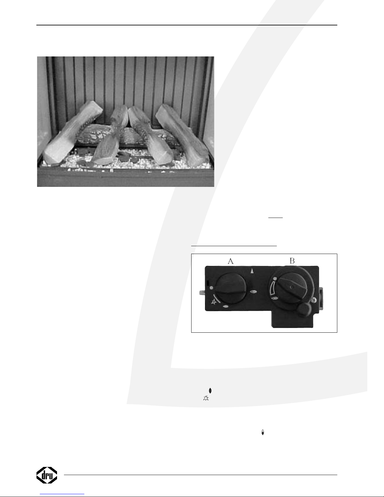
Plaatsen van de houtblokken
• Verdeel het vermiculiet gelijkmatig over de branderbak en
de bak er omheen, (bak voor vermiculiet). Het vermiculiet
zit in een plastic zakje bij de houtblokkenset.
• Leg het grote blok tegen de achterwand.
• Verdeel bovenop het vermiculiet een kleine hoeveelheid
bruine embers, zwarte en gele chips. Dit zit in zakjes bij
de houtblokkenset. De embers en chips geven een
gloeieffect op het branderbed.
• Let op: de zwarte en gele chips mogen alleen op de bak
voor vermiculiet gestrooid worden, niet op de branderbak.
• Let op dat er geen vermiculiet op of tussen de
waakvlambrander komt en dat de opening t.b.v. de overloop in de branderbak (sleufgat) vrij blijft van vermiculiet.
(zie fig. 6, pos 3).
• Plaats vervolgens de overige blokken zoals in fig.5 is
aangegeven.
De blokken mogen niet op een andere manier neergelegd
worden, omdat dan roetvorming kan ontstaan, ook mogen
de blokken niet tegen de waakvlambrander aan liggen.
Gebruik geen andere materialen dan die meegeleverd zijn.
De meegeleverde materialen zijn onbrandbaar en speciaal
voor dit toestel gemaakt.
Aansluiting van de gastoevoer
De gastoevoer aansluiten op het gasregelblok met 3/8"
BSP binnendraad.
In de aansluitleiding dient een goedgekeurde aansluitkraan
met koppeling te worden opgenomen (voor België moet
deze B.G.V. gekeurd zijn).
Ver der geldt:
• Ontlucht de toevoerleiding voordat het toestel wordt vastgekoppeld.
• De bedieningskraan mag niet verdraaid worden bij het aansluiten aan de gastoevoerleiding.
• Vermijd spanningen op de bedieningskraan en
leidingen.
• Controleer de aansluitingen op gasdichtheid.
Smoorring (fig. 6, blz 29)
De smoorring (pos 1) is afgesteld in de fabriek
op 8 mm. Deze afstand waarborgt een mooi
vlambeeld. Door een erkend installateur mag
deze afstand worden gevarieerd tussen de
twee streepjes op het spuitstuk (pos 2).
Hierdoor wordt het vlambeeld beïnvloeden.
Afstand vergrootten geeft "mooiere" vlammen,
waarbij de kans op roetvorming toeneemt,
(vervuiling van de ruiten). De afstand verkleinen geeft statische vlammen met meer gloei
op het branderbed.
Let op: Luchtopening mag nooit
worden afgesloten.
Let op de streepjes op de inspuiter.
GEBRUIKERSHANDLEIDING
Achter de klep onder aan het toestel bevinden zich de
knoppen waarmee het toestel kan worden bediend.
Aansteken
Knop A indrukken en linksom draaien tot de kleine
vlam .
Bij zal het toestel ontsteken. Controleer of de waakvlam brandt. (achter het glasraam ongeveer in het midden
achter de brander) Indien de waakvlam brandt, knop A nog
ca. 5 sec. geheel ingedrukt houden. Daarna knop A loslaten
en controleren of de waakvlam blijft branden. Draai nu
knop A naar de grote vlam . Hierdoor zal de hoofdklep
van het regelblok opengaan.Afhankelijk van de stand van
de regelknop B zal de hoofdbrander door de waakvlam
ontstoken worden.
4
INSTALLATIE VOORSCHRIFT GEBRUIKERSHANDLEIDING
fig. 5
fig. 7
Page 7
Afhankelijk van de stand van de regelknop B zullen hogere
of lagere vlammen te zien zijn.
Afstandsbediening
Met de afstandsbediening kan de vlamhoogte worden
geregeld. Knop B zal hierdoor draaien. Rechtsom geeft een
kleinere vlam, linksom geeft een grotere vlam. Indien knop
B met de hand bediend wordt zal hetzelfde resultaat worden bereikt. Het verdraaien van knop B moet met enige
kracht gebeuren, het klinken van tikken is hierbij volstrekt
normaal.
Waakvlamstand
Wanneer de kachel niet gebruikt wordt maar wel de
waakvlam moet branden kan knop A naar de kleine vlam
worden gedraaid. Hierdoor wordt de gastoevoer naar de
hoofdbrander afgesloten
Uitschakelen
Draai knop A rechtsom naar de "0" stand. De gastoevoer
naar de hoofd- en de waakvlambrander is dan gesloten.
Belangrijk
Een ingebouwde veiligheidsvergrendeling treedt in werking
wanneer het toestel op "0" stand, (gesloten stand) wordt
gezet.Wacht daarom 5 minuten alvorens het toestel
opnieuw te ontsteken. Probeer binnen deze tijd niet de
aansteekknop in te drukken, daar deze door de veiligheids
vergrendeling geblokkeerd is. Forceer de knop niet, omdat
het mechanisme dan kan worden beschadigd.
Draadloze bediening
De DIABLO wordt standaard geleverd met een draadloze
bediening. Het toestel is voorzien van een traploos regelbaar gasregelblok. De elektrische voeding wordt verzorgd
door batterijen. De levensduur van de batterijen is
ongeveer één jaar. De draadloze bediening werkt alleen
wanneer de waakvlambrander is ontstoken.
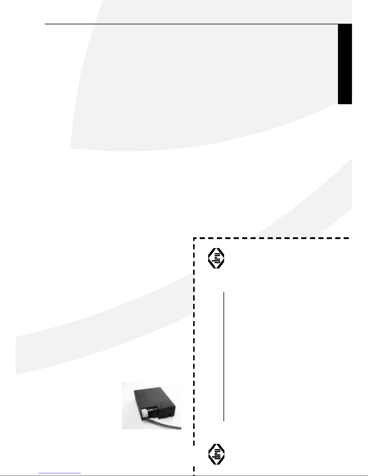
Aansluiten van de ontvanger
De draadloze bediening bestaat uit een ontvanger en een
afstandsbediening. Deze zijn samen verpakt in een doos.
De ontvanger moet worden aangesloten in het toestel
voordat de batterijen worden gemonteerd. Ga hiervoor als
volgt te werk:
• Neem de ontvanger uit de verpakking.
• Sluit de snoeren aan op de connectoren van het gasregelblok. De stekkers hebben verschillende maten en
corresponderen met de connectoren op het gasregelblok
(fig. 8).
• Neem de deksel los.
• Plaats de 4 penlite batterijen
(type AA). Let op de juiste
poolrichtingen.
• Plaats de deksel terug.
• Bevestig de ontvanger in het
bakje rechts achter de klep.
Zorg ervoor dat de rode led
naar voren wijst. Het snoer
moet door de uitsparing aan
de achterzijde lopen.
Vervangen van de batterijen in de ontvanger
• Verwijder de mantel.
• Rechts achter bevindt zich de ontvanger, in een houder
geschoven.
• Neem de ontvanger uit de houder. De achterzijde van de
ontvanger (met snoerdoorvoer) is afneembaar.Achter
deze deksel bevindt zich de batterijhouder.
• Verwijder de oude batterijen en plaats de nieuwe, let
daarbij op de + en – aansluiting van de batterijen en de
houder; deze moeten overeenkomen.
Plaatsen of vervangen van de batterijen in de
afstandsbediening
• Verwijder de deksel aan de onderzijde van de afstandsbediening.
• Sluit de blokbatterij (type 6LR61) aan op de clip.
• Plaats de batterij in de houder.
• Sluit de deksel.
• In de display staat de temperatuur aangegeven in
Fahrenheit, door beide knoppen enkele seconden ingedrukt te houden, verandert dit in Celsius.
LET OP: oude batterijen mogen niet bij het huisvuil maar
moeten bij het Klein Chemisch Afval.
Nederlands
GEBRUIKERSHANDLEIDING
fig. 8
✂
REGISTRATIEKAART
DRU Verwarming kan alleen garantie verlenen indien deze registratiekaart volledig en duidelijk
in blokletters en binnen 8 dagen opgestuurd is aan DRU Verwarming B.V.
Type: . . . . . . . . . . . . . . . . . . . . . . . . . . . . . . . . . . . . Aankoopdatum: . . . . . . . . . . . . . . . . . . . . . . . . . . . . . . .
Kleur: . . . . . . . . . . . . . . . . . . . . . . . . . . . . . . . . . . . Serienummer (op typeplaat): . . . . . . . . . . . . . . . . . . . . .
Koper: Detaillist/installateur:
Naam . . . . . . . . . . . . . . . . . . . . . . . . . . . . . . . . . . . Naam . . . . . . . . . . . . . . . . . . . . . . . . . . . . . . . . . . . . . . .
Adres . . . . . . . . . . . . . . . . . . . . . . . . . . . . . . . . . . . Adres . . . . . . . . . . . . . . . . . . . . . . . . . . . . . . . . . . . . . . .
Postcode . . . . . . . . . . . . . . . . . . . . . . . . . . . . . . . . . Postcode . . . . . . . . . . . . . . . . . . . . . . . . . . . . . . . . . . . .
Plaats . . . . . . . . . . . . . . . . . . . . . . . . . . . . . . . . . . . . Plaats . . . . . . . . . . . . . . . . . . . . . . . . . . . . . . . . . . . . . . .
Telefoon . . . . . . . . . . . . . . . . . . . . . . . . . . . . . . . . . Telefoon . . . . . . . . . . . . . . . . . . . . . . . . . . . . . . . . . . . . .
Hartelijk dank voor uw medewerking.
Page 8
ALGEMENE OPMERKINGEN
Onderhoud en reiniging
Periodiek onderhoud dient door een bevoegd installateur
te worden uitgevoerd. Het verdient aanbeveling om vóór
en tijdens het stookseizoen het toestel enkele malen stofvrij te maken. Na ingebruikname van het toestel kan zich
gedurende korte tijd wat witte aanslag vormen op de
binnenkant van het glas. Deze aanslag verwijderen met een
niet krassend reinigingsmiddel, zoals koperpoets of reiniger
voor keramische kookplaten. Daarnaast kan in de loop van
het gebruik altijd een zeer lichte aanslag optreden. Het
enkele malen per jaar reinigen van het glas is daarom normaal. Bij het reinigen van de mantel geen bijtende of schurende middelen gebruiken. Lakbeschadigingen, bijvoorbeeld
door het plaatsen van voorwerpen op de mantel vallen
buiten de garantie.
Let op: Bij het vervangen van het thermokoppel moet de
wartel in het gasregelblok handvast gedraaid worden,
waarna deze met een steeksleutel een kwartslag aangedraaid moet worden.
Ver kleuring van wanden en plafonds
Bruinverkleuring is een vervelend probleem en is moeilijk
op te lossen. Bruinverkleuring kan worden veroorzaakt
door onder andere stofverbranding veroorzaakt door te
weinig ventilatie, door het roken van sigaretten of het
branden van kaarsen.
Deze problemen kunnen worden voorkomen door:
Het vertrek waar het toestel zich bevind goed te ventileren. Een goede richtlijn hiervoor is (vlg. het Nederlands
Bouwbesluit):
Bij nieuwbouw : 3.24 m
3
/ uur per m
2
vloeroppervlak van een vertrek.
Bij bestaande bouw :25.20 m3/ uur voor een vertrek.
Maak zo weinig mogelijk gebruik van kaarsen en olielampjes en houd het verbrandingslontje zo kort mogelijk.
Deze "sfeerbrengers" zorgen voor aanzienlijke hoeveelheden vervuilde en ongezonde roetdeeltjes in uw woning.
Rook van sigaretten en sigaren bevat o.a. teerstoffen die bij
verhitting eveneens op koudere en vochtige muren zullen
neerslaan. Bij een nieuw gemetselde schouw of na een verbouwing wordt aanbevolen minimaal 6 weken te wachten
voordat men gaat stoken,het bouwvocht moet namelijk
geheel verdwenen zijn uit wanden, vloer en plafond.
Eerste maal stoken
Tijdens de eerste maal stoken kan er een onaangename
geur ontstaan, die wordt veroorzaakt door het uitdampen
van de lak. Dit verdwijnt na enkele uren.
Daarom raden wij u aan het toestel de eerste maal op de
hoogste stand te stoken terwijl u tevens het vertrek waarin de kachel staat goed ventileert.
Extra bescherming
Indien het toestel in een vertrek geïnstalleerd wordt waar
jonge kinderen of hulpbehoevende mensen zonder toezicht verblijven, is het wenselijk het toestel af te schermen.
Afdanken
Indien u het toestel vervangt of verwijdert, moet u het
toestel via de reguliere weg afvoeren.Voordat tot demontage wordt overgegaan eerst de aansluitkraan met koppeling dichtdraaien. De koppeling tussen aansluitkraan en toestel losdraaien. Het gehele toestel kan nu worden gedemonteerd en afgevoerd.
Garantie
De REGISTRATIEKAART gelieve binnen 8 dagen na aankoop in te vullen en op te sturen in een envelop zonder
postzegel naar het onderstaande adres.
DRU VERWARMING B.V.
ANTWOORDNUMMER 4551
6920 ZX DUIVEN
Het GARANTIEBEWIJS (blz. 1) kunt u zelf behouden.
De garantie gaat in op het ogenblik, dat de volledig ingevulde registratiekaart door DRU Verwarming is ontvangen.
VOOR BELGIË DE KAART INVULLEN OP PAGINA 19 EN 23
EN STUREN AAN DRU BELGIUM
ALGEMENE OPMERKINGEN
✂
VERSTUREN IN EEN
ENVELOP
Page 9
English
7
CONTENTS
CONTENTS
Foreword . . . . . . . . . . . . . . . . . . . . . . . . . . . . . . . . .8
Package . . . . . . . . . . . . . . . . . . . . . . . . . . . . . . . . . . .8
Instructions for installation . . . . . . . . . . . . . . . . . . . .8
General . . . . . . . . . . . . . . . . . . . . . . . . . . . . . . . . . . .8
Important . . . . . . . . . . . . . . . . . . . . . . . . . . . . . . . . .8
Type of gas . . . . . . . . . . . . . . . . . . . . . . . . . . . . . . . .8
Positioning . . . . . . . . . . . . . . . . . . . . . . . . . . . . . . . .8
Possible connections . . . . . . . . . . . . . . . . . . . . . . . . .8
Preparations for the installation of the
combined inlet-outlet system . . . . . . . . . . . . . . . . . .8
Wall duct concentric pipes . . . . . . . . . . . . . . . . . . . .9
Roof duct with concentric pipes . . . . . . . . . . . . . . . .9
Fitting the fire to an existing chimney . . . . . . . . . . . .9
Baffle . . . . . . . . . . . . . . . . . . . . . . . . . . . . . . . . . . . . .9
Glass window . . . . . . . . . . . . . . . . . . . . . . . . . . . . . .9
Positioning the logs . . . . . . . . . . . . . . . . . . . . . . . . .10
Connecting to the gas supply . . . . . . . . . . . . . . . . .10
Throttle ring . . . . . . . . . . . . . . . . . . . . . . . . . . . . . .10
Operating instructions . . . . . . . . . . . . . . . . . . . . . .10
Lighting . . . . . . . . . . . . . . . . . . . . . . . . . . . . . . . . . .10
Remote controle . . . . . . . . . . . . . . . . . . . . . . . . . .10
Pilot light setting . . . . . . . . . . . . . . . . . . . . . . . . . . .11
Switching off . . . . . . . . . . . . . . . . . . . . . . . . . . . . . .11
Important . . . . . . . . . . . . . . . . . . . . . . . . . . . . . . . .11
Remote control . . . . . . . . . . . . . . . . . . . . . . . . . . .11
Connecting the receiver . . . . . . . . . . . . . . . . . . . . .11
Replacing the batteries in the receiver . . . . . . . . . .11
Inserting or replacing the batteries
in the remote control . . . . . . . . . . . . . . . . . . . . . . .11
General notes . . . . . . . . . . . . . . . . . . . . . . . . . . . . .11
Gas safety regulations (for installation & use), 1998 11
Cleaning and Maintenance . . . . . . . . . . . . . . . . . . . .12
Discoloration of walls and ceiling . . . . . . . . . . . . . .12
Lighting the heater for the first time . . . . . . . . . . . .12
Extra protection . . . . . . . . . . . . . . . . . . . . . . . . . . .12
Disposal . . . . . . . . . . . . . . . . . . . . . . . . . . . . . . . . .12
Guarantee . . . . . . . . . . . . . . . . . . . . . . . . . . . . . . . .12
Technical data . . . . . . . . . . . . . . . . . . . . . . . . . . . . .25
WARRANTY CARD
Please complete this card and keep it with the invoice to verify purchase date
and to establish the warranty period*.
Model: . . . . . . . . . . . . . . . . . . . . . . . . . . . . . . . . . . . . . . . . . . . . Date: . . . . . . . . . . . . . . . . . . . . . . . . . . . . . . . . . . . . . . . . . . . . . . .
Colour: . . . . . . . . . . . . . . . . . . . . . . . . . . . . . . . . . . . . . . . . . . . . Serial No.: . . . . . . . . . . . . . . . . . . . . . . . . . . . . . . . . . . . . . . . . . . .
Type of Gas: Natural Gas ❑ L.P.G.❑ (please check)
Customer: . . . . . . . . . . . . . . . . . . . . . . . . . . . . . . . . . . . . . . . . . . Dealer/Installer:
Name . . . . . . . . . . . . . . . . . . . . . . . . . . . . . . . . . . . . . . . . . . . . Name . . . . . . . . . . . . . . . . . . . . . . . . . . . . . . . . . . . . . . . . . . . . . .
Address . . . . . . . . . . . . . . . . . . . . . . . . . . . . . . . . . . . . . . . . . . . . Address . . . . . . . . . . . . . . . . . . . . . . . . . . . . . . . . . . . . . . . . . . . . .
City . . . . . . . . . . . . . . . . . . . . . . . . . . . . . . . . . . . . . . . . . . . . City . . . . . . . . . . . . . . . . . . . . . . . . . . . . . . . . . . . . . . . . . . . . . . . .
State . . . . . . . . . . . . . . . . . . . . . . . . . . . . . . . . .ZIP . . . . . . . . State . . . . . . . . . . . . . . . . . . . . . . . . . . . . . . . . . . .ZIP . . . . . . . . .
Province . . . . . . . . . . . . . . . . . . . . . . . . . . . . . . . .P.C. . . . . . . . . Province . . . . . . . . . . . . . . . . . . . . . . . . . . . . . . . .P.C. . . . . . . . . .
Telephone ( . . . . . . . . . . . . . . . .) . . . . . . . . . . . . . . . . . . . . . . . . .
*FOR SERVICE UNDER THIS WARRANTY CONTACT YOUR DEALER/INSTALLER.
DIABLO
DRU warrants the proper functioning of this vented roomheater if installed by a qualified installer and if used in
strict accordance with the manufacturers operating instructions
GAS SAFETY (INSTALLATION & USE) REGULATIONS 1998
1. In your own interest and that of safety,it is law that all gas appliances shall be installed by competent persons in accordance with the above regulations. Failure to install appliances
correctly could lead to prosecution.Other persons should NOT attempt to install this equipment.
2. Unpack the appliance and check it carefully. If it appears to have any operating defect DO NOT INSTALL,but ontact the supplier.
3.This appliance is intended to be used to raise the temperature in a room or office etc.You should NOT use it for any other purpose without seeking advice from your supplier.
4.This appliance is safe if correctly installed and sited. Please comply CAREFULLY with the instructions.
5. Installation MUST be carried out in accordance with:
a. Building Regulations f. BS 5440:2:2000 and BS5440:Part 1:1990 (as amended)
b. if installed on a timber framed wall ,Institute of Gas Engineers publication DM2 g. IS 813:1996
c. Gas Safety (Installation and Use) Regulations 1998 h. Local Bye Laws
d. BS 6891 i. Children and Young Persons Act 1933 revised 1952
e. BS 5871:1980 j.
Such other specifications or legislation that may have superseded the above documents.
6. Should the heater be fitted in a room where there are young children,elderly,infirm or handicapped persons, it is strongly recommended that a guard is fixed around the heater.
Guards conforming to British Standards Specifications 6778: 1986 (Fireguards for use with portable free standing or wall mounted heating appliances) in respect of fixing strength and
paint finish are acceptable and overall dimensions should be such that there is a gap of a least 100mm (4 inches) between the guard and the heater.
Please be sure you are aware of the implications of all these notes.
DRU Verwarming B.V.
Conditions of warranty
• This appliance has been manufactured and tested by DRU verwarming BV of The Netherlands with utmost care.
• Subject to the conditions set out on this card DRU guarantees the proper operation of this vented room heater to the original purchaser for a period of one year after date of pur-
chase.
• Subject to the conditions set out on this card, the cast iron combustion chamber of your DRU vented room heater carries a full guarantee to the original purchaser for a period of
ten years after date of purchase.
• The guarantee does not cover the normal wear and tear,damage due to incorrect treatment, changes of the equipment or unauthorised installations and repairs.No liability is
assumed by DRU for removal or (re)installation labor costs.
• Under no circumstances shall DRU be liable for incidental,consequential, special or contingent damages or expenses arising directly or indirectly from any defect in the product or
any component or from the use thereof.The remedies set forth herein are the exclusive remedies available to the user and are in lieu of all other remedies. Subject to specific state
laws some of the above limitations or exclusions may not apply to you.
Page 10

Foreword
Dear Customer,
Thank you very much for buying this DRU produkt. Our
produkt have been developed and manufactured in compliance with the highest possible requirements with regard to
quality, performance and safety.This will allow you to enjoy
years of trouble-free use.
In this booklet you will find instructions for the installation
and use of your new wall-mounted heater.The appropriate
drawings can be found on pages 26-29. Please read these
instructions and the manual carefully in order to familiarize
yourself with the appliance. If you require any further support, please do not hesitate to contact your supplier.
Package
The complete set for a Diablo consists of two packages:
one for the appliance and one for the casing.The pipe and
the wall duct are delivered separately.
Ta ke the backsheet from the box and then take the appliance from the box.A special rosette is supplied with the
appliance that should be used instead of the rosette supplied with the mantel.
The casing can just be taken from the box.
Do not put the packing material with the regular household refuse, but see to it that it can be recycled again.
PLEASE NOTE:The stainless steel casing has been fitted
with protective foil.This foil should be removed before the
appliance is used.
INSTRUCTIONS FOR INSTALLATION
General
The Diablo is equipped with a closed combustion chamber.The combustion air is sucked in from outside by a
combined in- and outlet through the natural draught of the
appliance.Through the same natural draught the combustion gases are discharged
Important
• Keep curtains and any other flammable materials at least
50cm away form the appliance.
• Caution! Touching the heater when hot can cause burns
and blisters!
• The appliance should be installed and maintained by a
registered installer.
• Do not install any so-called dust filter on or under the
casing.
• Do not hang wet clothes and towels etc. on the heater
to dry!
Type of gas
Check if the local type of gas and the gas pressure are
similar to those mentioned on the identification plate.
The appliance has been factory-adjusted and sealed for
propane with a burner pressure of 29 mbar and a prepressure of 37 mbar. For variant pre-pressures, a qualified
fitter should adjust the burner pressure to 29 mbar.This
applies in NL, NO and DE. See the table of technical specifications on page 25.
Please keep to the gas installation regulations and any local
regulations. (Gas Safety (Installation & Use) Regulations
1998).
Positioning
• The temperature of the wall behind the appliance may
rise to 60ºC. Please keep this in mind when choosing the
wall and the wall covering.
• The sides of the appliance should be kept accessible
because of the heat the appliance may give off.For this,
allow for at least 50 cm on both sides.
• Allow for at least 50 cm free space to be available above
the appliance for the outlet of hot air.
• Take care that no curtains hang over the appliance
• The appliance should hang at least 10 cm above the
ground.
Possible Connections (fig. 2, page 26)
The heater duct can be connected either through the wall
or the roof, and should meet the following requirements:
• The first metre of pipe should always be fitted vertically;
• The length of horizontal pipe should never be more than
4 metres;
• The maximum length of pipe is 12 metres.
Allow 2 metres for a 90º bend, and 1 metre for a 45º
bend.When mounting the heater on a wall or the roof, the
thickness of the wall or roof does not have to be taken
into account.
The maximum total length is the sum of the pipe length
plus the substitute length for the bends (see the 4 examples in fig.2).
The roof duct, the air supply pipes / flue, concentric pipes
and bends are each packed separately and supplied complete with a clip binding with sealing ring.An adjustable tile
or adhesive flashing is also available to seal ducts through
either a slanting or flat roof.
NB: This appliance may only be installed using the flue
material ø150/ø80 supplied by DRU.This has been
approved together with the appliance to comply with all
requirements. DRU cannot guarantee that the appliance
will work correctly and safely if alternative installation
material is used.
Preparations for the installation of the combined inlet-outlet system
• Select the required connection from the options shown
in figure 2.
• Erect the concentric pipes from the heater up. If the
structural situation requires that the first section of the
concentric pipe system be built in, take special note of
the required method of assembly.
• The appliance has a coupling section; fit the first metre of
8
INSTRUCTIONS FOR INSTALLATION
Page 11

English
INSTRUCTIONS FOR INSTALLATION
9
pipe onto this.When correctly assembled, the blue rubber sealing ring inside the pipe should be visible from
the top.
• Allow at least 5 cm between the outside of the concentric pipes and the wall or ceiling.
Wall duct with concentric pipes
Ensure that the first metre of pipe used for the wall duct
is assembled vertically.
• Determine the position of the appliance and the position of the wall duct.
• Decide where to place the appliance and the wall duct.
• To do so, use the backsheet of the appliance.The centre
of the hole for the pipe (when using 1 m of pipe) should
come at 1130 mm above the edge of the backsheet (see
fig. 3 page 27).When using a longer piece of pipe, this
extra length should be added.
• Subsequently, install the backsheet at the right heigth on
the wall (please note the desired level of sight, e.g. bottom backside at 500 mm.The appliance will stick out 82
mm from under the backsheet).
• Then, make a hole of Ø 160 mm (Ø 180 mm max.).
• Now,connect one or more concentric pipes vertically
to the outlet of the appliance.When these pipes are
located in view, you may order matching varnished
pipes. Press the pipes together and apply the clamping
strip(s).The blue rubber ring will supply sufficient sealing
of the combustion gas discharge system.
• Slide the flange over the curve and attach it at 70 mm
from the edge with a self-tapper on the curve.
• Now,slide the curve with flange through the hole and
attach the flange to the wall.
• From the outside, measure the distance between the
outer wall and the edge of the curve. Saw the wall duct
to the length to the measure mentioned below.
The length of the wallduct:
The outer pipe = measured length +30mm.
The inner pipe = measured length +50mm.
• Slide the wall duct into the hole and see to it that the
edge falls within the wall duct.Attach the outer flange
to the wall.
PLEASE NOTE: Level the assembly sheet (2), take care
that the pipes fall to the outside (1cm to 1 m) and that
the outer flange lies directly against the outer wall. In this
way, it will be impossible for any condensation to run into
the heater.
Roof duct with concentric pipes
A duct through a roof can open out anywhere on the
roof, with an extension to the ridge if necessary.
Depending on which of the aforementioned options has
been chosen, the roof duct will be supplied with either
adhesive flashing for a flat roof or a universally adjustable
tile for a slanted roof.
• Determine the position of the appliance and the position of the chimney.
• Drill a ∆ 160 mm hole at the point where the chimney
is required.
• Now vertically connect the concentric pipes to the
heater outlet. Press well and apply the clip binding.The
blue rubber ring will sufficiently seal the flue system.
• Determine the length of the pipes required and ensure
that the adhesive flashing or the universal tile fit properly.
• Saw the pipe off at the length required.
• Connect the roof duct to the concentric pipes.
Fitting the fire to an existing chimney
The fire can be fitted into an existing chimney providing
that the chimney / flue dimensions are 150 mm or more.
A special flue kit is required, which can be obtained from
Drugasar or a Drugasar agent. Do not use any other type
of flue system for this.
BS 5871 – 1 : 2001
Any chimney previously used for an appliance burning a
fuel other than gas shall be swept thoroughly before
installing any gas appliance.
Appliances shall be connected only to the types and sizes
of flue system as specified.
For any other information about this flue system please
contact Drugasar or Drugasar approved agent.
Baffle (fig. 4, page 28-29)
A baffle is needed to ensure the correct working of the
appliance.The baffle is supplied separately and should be
fitted into the appliance as indicated in fig.4a. Using the
adjusting jig provided, (fig. 4b) the baffle can be adjusted
as required. Once it has been adjusted, fix the baffle in
place with the socket-head screw provided.
Adjusting the baffle:
Horizontal wall duct (max.
4 meter)
• 1-meter vertical pipe.
No baffle.
Vertical roof duct
• If the total calculated length of the pipe system is
between 1 and 6 meters.
Baffle at 60 mm.
• If the total calculated length of the pipe system is
between 7 and 12 meters.
Baffle at 54 mm.
Figure 2 shows how to calculate the total lengths.
Glass window
For the placing of the logs, the window should be
removed.To do so, proceed as follows:
• Remove the four screws of the safety strip of the window
• Take away the strip and subsequently the glass window.
• Make sure that the standing corner strips do not fall.
To r e-assemble the glass window please follow the procedure in reverse order.
When doing this, make sure that the glass window
securely seals the combustion chamber.
Broken or otherwise damaged glass should be replaced
immediately.
DIABLO
Page 12

For safety reasons a guard should be placed in
front of the fire at all times
Positioning the logs
• Sprinkle the vermiculite evenly over the burner tray and
the surrounding tray, (the vermiculite tray).The vermiculite
is in a plastic bag with the logs.
• Place the largest log against the back wall.
• Sprinkle a few brown embers,black and yellow chips on
top of the vermiculite to create a glowing effect on the
burner bed.The embers and chips are in little bags with
the log set.
• NB: The black and yellow chips are to be sprinkled in the
vermiculite tray only, not in the burner tray.
• Make sure that no vermiculite gets on or into the pilot
light burner, and that no vermiculite is blocking the overflow opening (slit) in the burner tray. (see fig. 6, pos 3).
• Now position the rest of the logs as illustrated in fig. 5.
The logs should not be laid in any other way as this could
cause the formation of soot. Neither should the logs touch
pilot light burner.
Do not use any materials other than those supplied.The
supplied materials are incombustible and have been manufactured specifically for this appliance.
Connecting to the gas supply
Connect the gas supply to the gas control valve with 3/8"
inner thread.
In the connecting pipe an approved connecting gas tap
with a coupling should be included.This should be placed
outside the casing.
Furthermore please note that:
• Expel all air from the supply pipe before coupling the
appliance.
• Do not turn the control tap when connecting the gas
supply.
• Avoid any tension on the control tap or
pipes.
• Check that the connection is gastight.
Throttle ring (fig. 6, page 29)
The throttle ring (pos 1) is factory-adjusted to
8 mm.This will produce attractive flames.A
qualified fitter may adjust the distance between
the two marks on the jet
(pos 2) to change the appearance of the
flames.The larger the flames, the more they
will "dance", but soot formation will also be
more likely (dirty windows).The smaller the
distance the more static the flames and the
more intense the glow on the burner bed.
NB:The air inlet may ne
ver be closed.
See the marks on the jet.
OPERATING INSTR
UCTIONS
The control buttons are located behind the flap at the bottom of the heater front.
Lighting
Press button A and turn to the left to the small flame .
The flame will ignite at . Check that the pilot light
behind the glass is alight. If that is the case, hold button A
firmly pressed for another 5 seconds.Then release button
A and check that the pilot light is still burning. Now turn
button A to the large flame , which will open the main
valve of the control block. Depending on the setting of the
control button B, high or low flames will be visible.
Remote control
The level of the flames can be regulated with the remote
10
INSTRUCTIONS FOR INSTALLATION OPERATING INSTRUCTIONS
fig. 7
fig. 5
Page 13

control, which will turn button B; to the right for a smaller
flame, to the left for a larger flame. Controlling button B
by hand will give the same result.This will require a certain
effort and it is quite normal to hear clicking.
Pilot light setting
If the heater is not in use but you would like the pilot light
to remain alight, set button A to the small flame.The gas
supply to the main burner will then be switched off.
Switching off
Turn button A to the "0" setting.The gas supply to the
burners will then be switched off.
Important
A built-in safety lock is activated when the appliance is
switched to "OFF" (closed down setting).Therefore, wait
5 minutes before relighting the heater.Within this period,
do not try to push the lighting button, as this has been
blocked by the safety lock. Do not force the button, as this
may result in damage to the mechanism.
Remote control
Remote control is supplied as a standard accessory.The
heater has a freely adjustable. Batteries, with a life
expectancy of approximately one year, feed the electrical
supply.The remote control will only work if the pilot light
is lit.
Connecting the receiver
The remote control system comprises a receiver and a
remote control, packed together in one box.The receiver
must be connected to the appliance fitting the batteries.
This is done as follows:
• Take the receiver out of the box.
• Connect the wires to the connectors on the gas control
valve.The different sized plugs correspond with the connectors on the gas control valve (fig. 8).
• Open the lid.
• Insert 4 penlight batteries
(type AA). Make sure they
are the right way round.
• Replace the lid.
• Fix the receiver in the tray
behind the flap on the right.
Make sure that the red LED
is pointing to the front.The
wire should run through
the opening at the back.
Replacing the batteries in the receiver
• Remove the casing.
• On the right, behind the reciever, is a holder.
• Take the receiver out of the holder.The back of the
receiver (with an opening for the wire) is removable.The
batteries are under that cover.
• Remove the old batteries and insert the new ones, mak-
ing sure that the + and – signs on the batteries correspond with those in the holder.
Inserting or replacing the batteries in the
remote control
• Remove the cover on the back of the remote control.
• Connect a square battery (type 6LR61) to the clip.
• Fit the battery in the holder.
• Replace the cover.
• The temperature is shown on the display in Fahrenheit,
press both buttons for a few seconds and it will change
to Celsius.
NB: Do not throw old batteries in the dustbin.They
should be treated as Chemical Waste.
GENERAL NOTES
Gas Safety Regulations (for installation & use) 1998
In your own interest and that of safety, it is law that all gas
appliances are installed by competent persons in accordance with the above regulations. Failure to install appliances correctly could lead to prosecution.
NB: The Confederation of Registered Gas
Installers, whose members are identified by the
emblem shown here, are all required to work to
the recognized standards.
English
GENERAL NOTES
fig. 8
✂
GUARANTEE REGISTRATION CARD
In order to register your guarantee, please complete and return this card(no stamp required)
Details of equipment:
Model: . . . . . . . . . . . . . . . . . . . . . . . . . . . . . . . . . . . Serial No.: . . . . . . . . . . . . . . . . . . . . . . . . . . . . . . . . . . .
Type of gas: Natural Gas ❑ L.P.G.❑ (please tick).
Model an serial no. are to be found on data badge inside heater.
Customer: Installed by:
Name . . . . . . . . . . . . . . . . . . . . . . . . . . . . . . . . . . . Name . . . . . . . . . . . . . . . . . . . . . . . . . . . . . . . . . . . . . . .
Address (of installation) . . . . . . . . . . . . . . . . . . . . . . Address . . . . . . . . . . . . . . . . . . . . . . . . . . . . . . . . . . . . .
Post Code . . . . . . . . . . . . . . . . . . . . . . . . . . . . . . . . Post Code . . . . . . . . . . . . . . . . . . . . . . . . . . . . . . . . . . .
Tel. No. . . . . . . . . . . . . . . . . . . . . . . . . . . . . . . . . . . Tel. No. . . . . . . . . . . . . . . . . . . . . . . . . . . . . . . . . . . . . .
Appliance installed in . . . . . . . . . . .(Office, Church, etc.)
Is appliance replacing alternative fuel: Solid Fuel ❑ Oil ❑ Electricity ❑ (please tick).
If replacing existing balanced flue heater make of original
Date of installation
N.B.Where more than one appliance installed, please complete all cards and return in envelope using freepost address on reserve.
Completion of this card in no way affects your statutory rights
Thank you DRUGASAR LIMITED
Page 14

Cleaning and Maintenance
Periodical maintenance must be carried out by a qualified
fitter.You are recommended to clean the appliance several
times before and after the heating season. Once the appliance has been used for a while, a white deposit can form
on the inside of the glass. This deposit can be removed
with a non-abrasive agent such as brass polish or a cleaner
for ceramic hobs.A very light deposit will also form occasionally as a result of use. So it will be quite normal to
clean the glass several times a year. Do not use corrosive
or abrasive agents to clean the casing.The guarantee does
not cover any damage to the surface caused, for example,
by objects put on top of it.
NB: When replacing the thermocouple, the coupling nut in
the gas control block should first be tightened by hand and
then tightened a quarter-turn with an open-ended spanner.
Discoloration of walls and ceiling
Brown discoloration is an annoying problem, which is difficult to solve. It can be caused by dust burning as a result
of poor ventilation, for example, or by cigarette smoke or
candles.
These problems can be avoided by ensuring that the room
the heater is in is properly ventilated.A good guideline for
ventilation is:
New buildings : 3.24 m
3
/ hour per m2floor
surface of the room.
Existing buildings : 25.20 m
3
/ hour for a room.
Use candles and oil lamps as little as possible, keeping the
wick as short as possible.While they enhance the atmosphere, candles and oil lamps also cause the formation of
large quantities of unhealthy soot particles in your home.
Cigarette and cigar smoke contains tar, which upon heating
will precipitate on cold or damp walls. If you have a newly
cemented chimney or have had any other reconstructions
/ renovations done, you are advised to wait at least 6
weeks before lighting your fire, to allow the walls, floor
and ceiling to dry out completely.
Lighting the heater for the first time
During the first use, an unpleasant smell may occur, caused
by the vapour of the varnish.This will vanish after some
hours.
That is why we advise you to use the appliance for the
first time on its highest setting, while at the same time
thoroughly ventilating the room in which the heater is
placed.
Extra protection
This heater meets the normal safety standards regarding
surface temperatures, but physical contact with heated surfaces should be avoided where possible. An additional
guard is recommended to protect young children and elderly, infirmed or handicapped people.
Disposal
When replacing or otherwise removing the appliance, it
should be disposed of in compliance with current regulations.
Shut off the connecting tap with coupling before commencing disassembly. Undo the coupling between the connecting tap and the appliance.The whole appliance can
now be disassembled and removed.
Guarantee
Please complete the enclosed REGISTRATION CARD and
post it in an envelope (no stamp required) to the address
below within 8 days of purchase.
DRUGASAR LIMITED
FREEPOST
DEANS ROAD
SWINTON
MANCHESTER M27 1 BX
Please retain the GUARANTEE CARD (page 7) for your
own reference.The guarantee will become effective upon
receipt by DRUGASAR Limited of the fully completed
registration card.
GENERAL NOTES
✂
PLEASE SEND IN AN
ENVELOPE
DRUGASAR, GAS HEATING FOR PEOPLE WHO DON’T HAVE MONEY TO BURN.
Page 15

Deutsch
13
INHALT
Einige kurze Worte . . . . . . . . . . . . . . . . . . . . . . . . .14
Verpackung . . . . . . . . . . . . . . . . . . . . . . . . . . . . . . .14
Installationsvorschrift . . . . . . . . . . . . . . . . . . . . . . .14
Allgemein . . . . . . . . . . . . . . . . . . . . . . . . . . . . . . . .14
Wichtig . . . . . . . . . . . . . . . . . . . . . . . . . . . . . . . . . .14
Gassorte . . . . . . . . . . . . . . . . . . . . . . . . . . . . . . . . .14
Aufstellen . . . . . . . . . . . . . . . . . . . . . . . . . . . . . . . .14
Anschlussmöglichkeiten . . . . . . . . . . . . . . . . . . . . . .14
Vorbereitung für den Einbau
des Zu- und Abluftsystems . . . . . . . . . . . . . . . . . . .15
Aussenwanddurchführung mit
konzentrischen Rohren . . . . . . . . . . . . . . . . . . . . . .15
Dachdurchführung mit konzentrischen Rohren . . . .15
Bestehender Schornstein . . . . . . . . . . . . . . . . . . . .15
Restriktionsschieber . . . . . . . . . . . . . . . . . . . . . . . .15
Glasfenster . . . . . . . . . . . . . . . . . . . . . . . . . . . . . . .16
Einlegen der Holzblöcke . . . . . . . . . . . . . . . . . . . . .16
Anschluss an die Gaszufuhr . . . . . . . . . . . . . . . . . .16
Drosselring . . . . . . . . . . . . . . . . . . . . . . . . . . . . . . .16
Gebrauchsanweisung . . . . . . . . . . . . . . . . . . . . . . . .16
Zünden . . . . . . . . . . . . . . . . . . . . . . . . . . . . . . . . . .16
Fernbedienung . . . . . . . . . . . . . . . . . . . . . . . . . . . .16
Zündflammenstand . . . . . . . . . . . . . . . . . . . . . . . . .17
Ausschalten . . . . . . . . . . . . . . . . . . . . . . . . . . . . . . .17
Wichtig . . . . . . . . . . . . . . . . . . . . . . . . . . . . . . . . . .17
Drahtlose Bedienung . . . . . . . . . . . . . . . . . . . . . . . .17
Anschliessen des Empfängers . . . . . . . . . . . . . . . . .17
Ersetzen der Batterien im Empfänger . . . . . . . . . . .17
Einlegen oder Ersetzen der Batterien in der
Fernbedienung . . . . . . . . . . . . . . . . . . . . . . . . . . . .17
Allgemeine Bemerkungen . . . . . . . . . . . . . . . . . . . .18
Wartung und Reinigung . . . . . . . . . . . . . . . . . . . . .18
Verfärbung von Wänden und Decken . . . . . . . . . . .18
Zum ersten Mal heizen . . . . . . . . . . . . . . . . . . . . . .18
Extra Schutz . . . . . . . . . . . . . . . . . . . . . . . . . . . . . .18
Entsorgen . . . . . . . . . . . . . . . . . . . . . . . . . . . . . . . .18
Garantie . . . . . . . . . . . . . . . . . . . . . . . . . . . . . . . . .18
Technischen Daten . . . . . . . . . . . . . . . . . . . . . . . . .25
INHALT
GARANTIEERKLÄR
UNG
Bitte vollständig ausfüllen und zusammen
mit Ihrer Einkaufsrechnung aufbewaren. (Blockschrift)
Type: . . . . . . . . . . . . . . . . . . . . . . . . . . . . . . . . . Kaufdatum: . . . . . . . . . . . . . . . . . . . . . . . . . . . . .
Farbe: . . . . . . . . . . . . . . . . . . . . . . . . . . . . . . . . .
Kaufer: Händler:
Name . . . . . . . . . . . . . . . . . . . . . . . . . . . . . . . . . Name . . . . . . . . . . . . . . . . . . . . . . . . . . . . . . . . .
Straße . . . . . . . . . . . . . . . . . . . . . . . . . . . . . . . . Straße . . . . . . . . . . . . . . . . . . . . . . . . . . . . . . . . .
PLZ. und Ort . . . . . . . . . . . . . . . . . . . . . . . . . . . PLZ. und Ort . . . . . . . . . . . . . . . . . . . . . . . . . . . .
BEI STÖR
UNGEN WENDEN SIE SICH BITTE ZUERST AN IHREN LIEFERANTEN.
DRU Verwarming garantiert die gute Wirkungsweise des Gerätes bei fachgerechter Installation
und Gebrauch lt. Gebrauchsanweisungen.
Garantiebestimmungen
• DRU Verwarming B.V. garantiert die Haltbarkeit des Gerätes durch Verwendung von hochwertigem Material.
• Die Garantie ist gültig für 1 Jahr ab Kaufdatum.
• Eingeschlossen sind alle Schäden am Gerät, die eine Folge von Fehlern in der Konstruktion oder für die Konstruktion benötigten Teile sind.
• DRU Verwarming verpflichtet sich,während der Garantiezeit beschädigte Teile kostenlos zu ersetzen oder auszutauschen.
• Die Garantieleistung verfällt, wenn Schäden als Folge von unsachgemäßer Nutzung entstehen, wenn das Gerät fehlerhaft aufgestellt wurde, wenn Unbefugte
Reparaturen ausführen oder wenn am Gerät keine Originalteile verwendet werden
• Die Garantie gilt nicht für Scheiben und Keramik.
DRU Verwarming B.V.
DIABLO
Page 16

Einige kurze Worte
Sehr geehrter Kunde,
Herzlichen Dank für den Kauf dieses DRU Produktes.
Unsere Produkte sind nach den höchsten Qualitäts-,
Leistungs und Sicherheitsanforderungen hergestellt.An
unseren Produkten haben Sie jahrelang ohne Probleme
Freude.
In diesem Heft finden Sie Instruktionen zur Installation und
zum Gebrauch Ihres neuen Heizofens. Für die dazugehörigen Zeichnungen siehe Seite 26-29. Lesen Sie die
Instruktionen und die Gebrauchsanleitung gut durch, damit
Sie sich mit dem Gerät vertraut machen können. Möchten
Sie mehr Unterstützung, nehmen Sie mit unserem
Lieferanten Kontakt auf.
Ver packung
Der gesamte Satz für den Diablo besteht aus zwei
Verpackungen: Einer für das Gerät und einer für den
Mantel.
Das Rohr und die Mauerdurchfuhr werden extra geliefert.
Holen Sie die rückwärtige Platte aus der Verpackung und
danach das Gerät. Zu dem Gerät wird gleichzeitig eine
extra Rosette mitgeliefert. Diese muß anstelle der bei dem
Mantel mitgelieferten Rosette gebraucht werden.
Der Mantel kann so aus dem Karton genommen werden.
Werfen Sie die Verpackung nicht zum normalen Hausabfall,
sondern sorgen Sie dafür, dass sie wieder verwendet werden kann.
ACHTUNG: Der RVS-Mantel ist mit einer Schutzfolie
versehen. Diese Folie muss entfernt werden, bevor das
Gerät in Gebrauch genommen wird.
INST
ALLATIONSVORSCHRIFT
Allgemein
Der Diablo ist mit einem geschlossenen Verbrennungsraum
versehen. Die Verbrennungsluft wird mit einer kombinierten Ein- und Ausfuhr durch den natürlichen Zug von aussen angesaugt. Durch den gleichen, natürlichen Zug werden
die Verbrennungsgase abgeführt.
Wichtig
Sorgen Sie dafür, dass Gardinen und andere brennbare
Materialien mindestens 30 cm vom Gerät entfernt sind.
Achtung! Anfassen von heissen Teilen kann Brandblasen
verursachen!
Das Gerät muss von einem anerkannten Installateur installiert und gewartet werden (in Belgien nach NBN D 51-003).
Das Anbringen eines sogenannten Staubfilters auf oder
unter dem Mantel ist nicht erlaubt.
Nasse Kleidung, Handtücher u. Ä.nicht zum Trocknen über
den Ofen hängen!
Gassorte
Kontrollieren Sie die Gassorte und den örtlichen
Gasdruck mit dem der Typenplatte.
Das Gerät ist in der Fabrik auf Propangas mit einem
Brennerdruck von 29 mbar und einem Vordruck von
37 mbar abgestellt und versiegelt. Bei abweichenden
Vor drucken muß der Brennerdruck von einem anerkannten Installateur auf 29 mbar eingestellt werden. Dies gilt
für NL, NO en DE. Siehe Tabelle technische Daten
Seite 25. Halten Sie sich an die Gasinstallationsvorschriften
und eventuelle örtliche Vorschriften.
Aufstellen
• Die Temperatur der Wand hinter dem Gerät kann bis auf
60˚C ansteigen. Bei Wand und Wandbekleidung müssen
Sie hiermit Rechnung tragen.
• Die Seiten des Geräts müssen wegen der Wärme, die das
Gerät abgibt, zugänglich bleiben. Rechnen Sie hierfür
minimal 50 cm an beiden Seiten.
• Sorgen Sie dafür, dass mindestens 50 cm freier Raum zur
Abfuhr von warmer Luft über dem Gerät vorhanden ist.
• Achten Sie darauf, dass keine Gardinen über dem Gerät
hängen.
• Das Gerät muss minimal 10 cm über dem Fussboden
hängend angebracht werden.
Anschlussmöglichkeiten (Fig.2, St. 26)
Die Durchfuhr dieser Heizofen kann sowohl durch den
Giebel, als auch durch das Dach angeschlossen werden.
Diese Durchfuhr muss den unten stehenden Vorschriften
entsprechen.:
• Immer erst ein Rohr mit der Länge von 1 m vertikal
positionieren.
• Die Rohrlänge darf horizontal nie mehr als 4 m betragen.
• Die maximale (totale) Gesamtlänge (des Rohres) beträgt
12 m.
Nehmen Sie für eine Biegung von 90° 2 Meter und für eine
Biegung von 45° 1 Meter. Beim Anschluss an den Giebel
oder auf das Dach braucht die Länge der Durchfuhr nicht
mitgerechnet zu werden.
Die maximale Gesamtlänge ist die Summe der Rohrlänge
plus der zusätzlichen Länge für die Biegung (siehe die 4
Beispiele in Fig.2).
Der Dachdurchführungssatz, Luftanfuhr / Rauchgasabfuhr,
das konzentrische Rohr und die Biegungen werden einzeln
verpackt und komplett mit einem Klemmband geliefert, das
mit einem Dichtungsring versehen ist. Zudem sind eine
Dachpfanne und eine Klebeplatte für die Durchführung
durch ein Schrägdach bzw. durch ein Flachdach erhältlich.
ACHTUNG: Dieses Gerät darf ausschließlich mit dem
von der DRU gelieferten Abfuhrmaterial ø150/ø80 installiert werden. Dieses ist zusammen mit dem Gerät geprüft
und entspricht damit allen Anforderungen. Bei abweichendem Installationsmaterial kann DRU nicht für eine gute
und sichere Funktion garantieren.
14
INSTALLATIONSVORSCHRIFT
Page 17

Deutsch
15
Vorbereitung für den Einbau des Zu- und
Abluftsystems
• Entscheiden Sie sich für eine der Anschlussmöglichkeiten
gemäss Fig. 2.
• Bauen Sie die konzentrischen Rohre vom Gerät aus auf.
Wenn aus baulichen Gründen erst ein Teil des konzentrischen Rohrsystems eingebaut wird, achten Sie bitte
besonders auf die richtige Montageart.
• Das Gerät beginnt mit einem Anschlussstutzen. Darauf
wird der erste Meter des Rohrs gesetzt. Bei einer guten
Montage sieht man von oben den blauen
Gummidichtungsring im Rohr.
• Halten Sie einen Mindestabstand von 5 cm zwischen der
Aussenseite der konzentrischen Rohre und der Wand
oder Decke ein.
Aussenwanddurchführung mit konzentrischen
Rohren
Beachten Sie bitte, dass bei der Aussenwanddurchführung
erst 1 m Rohr vertikal montiert werden muss.
Bestimmen Sie den Platz des Gerätes und die Stelle der
Giebeldurchfuhr.
• Gebrauchen Sie hierfür die rückw. Platte des Gerätes.
Die Mitte des Lochs für das Rohr muss bei 1 m Rohr auf
1130 mm über den Rand der rückw. Platte kommen
(siehe Zeichng. 3 St. 27).Bei grösserer Länge muss diese
extra Länge dazugezählt werden.
• Montieren Sie danach die rückw. Platte in der richtigen
Höhe auf die Mauer (achten Sie hierbei auf die
gewünschte Sichthöhe, z. B.Unterseite rückw. Platte auf
500 mm). Das Gerät kommt 82 mm unter der rückw.
Platte hervor).
• Machen Sie dann auf der Stelle der Giebeldurchfuhr ein
Loch von 160 mm Ø (maximal 180 mm Ø).
• Schliessen Sie nun eine oder mehrere konzentrischen
Rohre vertikal auf die Ausmündung des Geräts an.Wenn
diese Rohre sichtbar sind, können Sie dazu passende,
lackierte Rohre bestellen. Drucken Sie die Rohre an und
bringen Sie das/die Klemmband(bänder) an. Der blaue
Gummiring sorgt für eine ausreichende Abdichtung des
Verbrennungsabfuhrsystems.
• Schieben Sie die Rosette über das Knie und befestigen
Sie diese 70 mm vom Rand entfernt mit einer Schraube
mit selbstdrehendem Gewinde auf dem Knie.
• Schieben Sie nun das Knie mit Rosette durch das Loch
und befestigen Sie die Rosette an der Mauer.
• Messen Sie von aussen den Abstand von der
Aussenmauer bis zum Rand des Knies. Sägen Sie die
Mauerdurchfuhr auf unten stehende Länge.
Die Länge der Mauerdurchfuhr:
Das Aussenrohr = gemessene Länge + 30 mm.
Das Innenrohr = gemessene Länge + 50 mm.
• Schieben Sie die Mauerdurchfuhr in das Loch und sorgen
Sie dafür, dass das Knie in die Mauerdurchfuhr kommt.
Befestigen Sie die Aussenrosette auf der Mauer.
ACHTUNG: Stellen Sie die Montageplatte (2) mit der
Wasserwaage, sorgen Sie dafür, dass die Rohre nach aussen hin ablaufen (1 cm auf 1 m) und dass die
Aussenrosette gerade auf der Mauer liegt. Eventuelles
Kondenzwasser kann dann niemals in den Ofen gelangen.
Dachdurchführung mit konzentrischen Rohren
Eine Dachdurchführung kann in jeden Punkt des Daches
münden, eventuell mit einer Verlängerung zum Dach.
Die Dachdurchführung wird je nach einer der vorher
genannten Möglichkeiten mit einer Klebeplatte für ein
Flachdach geliefert, oder mit einer universell verstellbaren
Dachpfanne für ein Schrägdach.
• Legen Sie den Platz des Geräts und den Platz der
Durchführung fest.
• Machen Sie an der Stelle der Dachdurchführung ein
Loch von 160 mm Ø.
• Schliessen Sie die konzentrischen Rohre vertikal an der
Mündung des Geräts an. Bringen Sie das Klemmband an
un drücken Sie die Rohre an. Der blaue Gummiring
sorgt für eine ausreichende Ab-dichtung des
Abfuhrsystems für Verbrennungsgase.
• Legen Sie die Länge der benötigten Rohre fest und sorgen Sie dafür, dass die Klebeplatte oder die
Universaldachpfanne gut an das Dach anschliessen.
• Sägen Sie das Rohr in der richtigen Länge ab.
• Schliessen Sie die Dachdurchführung an die konzentrischen Rohre an.
Bestehender Schornstein
Es ist auch möglich, den Diablo an einen bestehenden
Schornstein anzuschliessen. Hierfür wird von DRU ein
spezialer Schornsteinanschlusssatz geliefert. Darin finden
Sie auch eine Installationsvorschrift für diesen
Anschlusssatz.
Bei Anschluss an einen bestehenden Schornstein sind die
folgenden Punkte wichtig:
• Der Schornstein muss minimal 150 mm Ø haben.
• Der Schornstein muss gut gereinigt werden.
• Die Gesamtlänge darf nicht mehr als 12 m und nicht
mehr als 4 m horizontal betragen.
Restriktionsschieber (Fig. 4, Seite 28-29)
Zu einer garantiert guten Funktion des Gerätes muß man
einen Restriktionsschieber einstellen.
Der Restriktionsschieber wird lose mitgeliefert und muß
lt. Fig. 4a in dem Gerät angebracht werden. Mit Hilfe der
mitgelieferten Abstellschablone (Fig. 4b) kann der Schieber
auf das richtige Maß abgestellt werden. Nach dem
Abstellen kann der Restriktionsschieber mit dem
Inbusbolzen festgesetzt werden.
Einstellen Restriktionsschieber:
Horizontale Mauer
durchfuhr (maximal 4 Meter)
• Mit 1 Meter vertikalem Rohr.
Kein Restriktionsschieber.
V
ertikale Dachdurchfuhr
• Wenn die berechnete Gesamtlänge des Rohrsystems
1 - 6 Meter beträgt.
Restriktionsschieber auf 60 mm.
• Wenn die berechnete Gesamtlänge des Rohrsystems 7 -
INSTALLATIONSVORSCHRIFT
DIABLO
Page 18

12 Meter beträgt.
Restriktionsschieber auf 54 mm.
In Figur 2 ist illustriert, wie die Gesamtlängen berechnet
werden müssen.
Glasfenster
Vor dem Einlegen der Holzblöcke muss das Fenster entfernt werden.Arbeiten Sie dabei folgendermassen:
• Entfernen Sie die vier Schrauben von der
Sicherheitsleiste des Glasfensters.
• Nehmen Sie die Leiste und danach das Glasfenster fort.
• Achten Sie darauf, dass die stehenden Eckenleisten nicht
fallen.
Zur Montage des Glasfensters nehmen Sie die umgekehrte
Prozedur. Sorgen Sie aber dafür, dass das Glasfenster die
Verbrennungskammer gut abdichtet.
Bei Beschädigung oder Bruch das Fenster sofort ersetzen.
Einlegen der Holzblöcke
• Verteilen Sie das Vermiculit gleichmäßig über und rund
um den Brennerbehälter, (Behälter für das Vermiculit).
Das Vermiculit befindet sich in einer Plastiktüte beim
Holzblocksatz.
• Legen Sie den großen Block gegen die Rückwand.
• Verteilen Sie über dem Vermiculit und kleine Mengen des
braunen Embers, schwarzen und gelben Chips. Dies
erzeugt einen Glüheffekt auf dem Brennerbett. Die
Embers und Chips befindet sich in Tütchen bei dem
Holzblocksatz.
• Achtung: Die schwarzen und gelben Chips dürfen nur
auf den Behälter für das Vermiculit gestreut werden, nicht
auf den Brennerbehälter.
• Achten Sie darauf, daß kein Vermiculit auf oder zwischen
den Zündflammenbrenner kommt und daß die Öffnung
für den Überlauf im Brennerbehälter (Rille) frei bleibt
von Vermiculit. (s. Fig. 6, Pos. 3).
• Legen Sie danach die übrigen Blöcke ein, wie in Fig. 5
angegeben ist.
Die Blöcke dürfen nicht auf eine andere Weise eingelegt
werden, weil sonst Rußbildung entstehen kann.
Auch dürfen die Blöcke nicht am Zündflammenbrenner
anliegen, da dies die Wirkung der Rauchgassicherung nachteilig beeinflussen kann.
Gebrauchen Sie keine anderen Materialien als die mitgelieferten. Die mitgelieferten Materialien sind nicht brennbar
und spezial für dieses Gerät angefertigt.
Anschluss an die Gaszufuhr
Die Gaszufuhr anschliessen an den Gasregelarmatur mit
3/8" BSP Innengewinde.
In der Anschlussleitung muss ein zugelassener
Anschlusshahn mit Kupplung aufgenommen werden. Dieser
muss ausserhalb des Mantels angebracht werden.
Weiterhin gilt:
• Entlüften Sie die Zuleitung, bevor das Gerät angekoppelt
wird.
• Der Bedienungshahn darf beim Anschluss an die
Gaszufuhrleitung nicht verdreht werden.
• Vermeiden Sie Spannungen auf dem Bedienungshahn und
den Leitungen. Dadurch besteht die Möglichkeit eines
Gasleks.
• Kontrollieren Sie den Anschluss auf
Gasdichtheit.
Drosselring (Fig. 6, Seite 29)
Der Drosselring (Pos. 1) ist in der Fabrik auf
8 mm abgestellt. Dieser Abstand garantiert
ein schönes Flammenbild.Von einem anerkannten Installateur darf dieser Abstand zwischen
den zwei Strichen auf der Spritzdüse (Pos. 2)
variierend verändert werden. Hierdurch wird
das Flammenbild beeinflußt. Ein vergrößerter
Abstand gibt ein „schöneres Flammenbild",
wobei die Rußformung zunehmen kann,
(Verschmutzung der Scheiben). Der verkleinerte Abstand ergibt statische Flammen mit
mehr Glut auf dem Brennerbett.
Achtung: Luftöffnung darf niemals
abgeschlossen werden.Achten Sie auf die Striche
auf der Einspritzdüse.
GEBRAUCHSANWEISUNG
Hinter der Klappe an der Vorderseite des Gerätes befinden
sich die Knöpfe, mit denen der Ofen bedient werden kann.
Zünden
Knopf A eindrücken und links herum drehen, bis zum
Zeichen .
Bei wird das Gerät zünden. Kontrollieren Sie, ob die
Zündflamme hinter dem Sichtfenster brennt. Brennt die
Zündflamme, Knopf A noch ca. 5 Sek. ganz eingedrückt halten. Danach Knopf A loslassen und kontrollieren, ob die
Zündflamme anbleibt. Drehen Sie nun Knopf A zur grossen
Flamme . Hierdurch wird sich die Hauptklappe des
Regelblocks öffnen.
Abhängig vom Stand des Bedienungsknopfes B werden
höhere oder niedrigere Flammen sichtbar.
16
INSTALLATIONSVORSCHRIFT GEBRAUCHSANWEISUNG
fig. 5
Page 19

Fernbedienung
Indem man Knopf B mit der Fernbedienung betätigt, lässt
sich die Flammenhöhe regeln. Dreht man nach rechts, werden die Flammen niedriger, dreht man nach links, werden
sie höher. Knopf B kann aber auch mit der Hand bedient
werden. Damit erzielt man das gleiche Ergebnis. Es ist
dafür ein wenig Kraft erforderlich und während des
Drehens wird ein Ticken zu hören sein.
Zündflammenstand
Wenn der Ofen nicht benutzt wird, aber wohl die
Zündflamme brennen muss, kann Knopf A zur kleinen
Flamme hin gedreht werden. Hierdurch wird die Gaszufuhr
zum Hauptbrenner abgeschlossen.
Ausschalten
Drehen Sie Knopf A zum „0"- Stand. Die Gaszufuhr zum
Brenner ist dann abgeschlossen.
Wichtig
Eine eingebaute Sicherheitsverriegelung tritt ein, wenn das
Gerät auf „0"-Stand, (Aus-Stand) gestellt wird.Warten Sie
darum 5 Minuten,bevor Sie das Gerät wieder aufs neue
zünden.Versuchen Sie in dieser Zeit nicht, den Zündknopf
einzudrücken, da dieser durch die Sicherheitsverriegelung
blockiert ist. Drehen Sie nicht mit Gewalt an dem Knopf,
weil der Mechanismus beschädigt werden könnte.
Drahtlose Bedienung
Der Ofen wird Standard mit einer drahtlosen Bedienung
geliefert. Das Gerät ist mit einem stufenlos regelbaren
Gasregelblock versehen. Die elektrische Speisung geschieht
mittels Batterien. Die Lebensdauer der Batterien ist ungefäht ein Jahr. Die drahtlose Bedienung funktioniert nur
dann, wenn der Zündflammenbrenner brennt.
Anschliessen des Empfängers
Die drahtlose Bedienung besteht aus einem Empfänger und
einer Fernbedienung. Diese sind zusammen in einem
Karton verpackt. Der Empfänger muss im Gerät angeschlossen werden, bevor die
Batterien montiert sind.
Arbeiten Sie hierfür folgendermassen:
• Nehmen Sie den Empfänger
aus der Verpackung.
• Schliessen Sie die Kabel an
die Konnektoren des
Gasregelblocks an. Die
Stecker haben verschiedene Masse und korrespondieren
mit den Konnektoren des Gasregelblocks (fig. 8).
• Öffnen Sie den Deckel.
• Legen Sie die 4 Penlite Batterien (Type AA) ein.Achten
Sie auf die richtigen Polrichtungen.
• Bringen Sie den Deckel wieder auf seinen Platz.
• Befestigen Sie den Empfänger in dem Behälter rechts hinter der Klappe. Sorgen Sie da-für, dass die rote Led nach
vorne zeigt. Das Kabel muss durch die Aussparung an der
Rückseite laufen.
Ersetzen der Batterien im Empfänger
• Entfernen Sie den Mantel.
• Rechts hinten befindet sich der Empfänger, der in eine
Halterung geschoben ist.
• Nehmen Sie den Empfänger aus der Halterung. Die
Rückseite des Empfängers (mit Kabeldurchfuhr) ist
abnehmbar. Hinter diesem Deckel befindet sich die
Batterienhalterung.
• Entfernen Sie die alten Batterien und legen sie die Neuen
ein.Achten Sie dabei auf den + und –An-schluss der
Batterien und der Halterung; diese müssen übereinstimmen.
Einlegen oder Ersetzen der Batterien in der
Fernbedienung
• Entfernen Sie den Deckel an der Unterseite der
Fernbedienung.
• Schliessen Sie die Blockbatterien (Type 6LR61) an die
Klemme an.
Deutsch
GEBRAUCHSANWEISUNG
fig. 7
✂
REGISTRIERKARTE
DRU Verwarming kann die Garantie nur übernehmen, wenn diese Registrierkarte vollständig in
Blockschrift ausgefüllt ist und innerhalb 8 Tagen nach Kauf an DRU Verwarming abgeschickt wird.
Type: . . . . . . . . . . . . . . . . . . . . . . . . . . . . . . . . . . . . Kaufdatum: . . . . . . . . . . . . . . . . . . . . . . . . . . . . . . . . . . .
Farbe: . . . . . . . . . . . . . . . . . . . . . . . . . . . . . . . . . . .
Käufer: Händler:
Name . . . . . . . . . . . . . . . . . . . . . . . . . . . . . . . . . . . Name . . . . . . . . . . . . . . . . . . . . . . . . . . . . . . . . . . . . . . .
Straße . . . . . . . . . . . . . . . . . . . . . . . . . . . . . . . . . . . Straße . . . . . . . . . . . . . . . . . . . . . . . . . . . . . . . . . . . . . .
PLZ. und Ort . . . . . . . . . . . . . . . . . . . . . . . . . . . . . . PLZ. und Ort . . . . . . . . . . . . . . . . . . . . . . . . . . . . . . . . .
Tel.-Nr. . . . . . . . . . . . . . . . . . . . . . . . . . . . . . . . . . . Tel.-Nr. . . . . . . . . . . . . . . . . . . . . . . . . . . . . . . . . . . . . . .
fig. 8
Page 20

• Legen Sie die Batterie in die Halterung.
• Schliessen Sie den Deckel.
• Im Display ist die Temperatur angegeben in Fahrenheit,
wenn Sie beide Knöpfe einige Sekunden eingedrückt halten, verändert dies in Celsius.
ACHTUNG: Alte Batterien gehören nicht zum Hausabfall
sondern in die Tonne für kleine, chemische Abfälle.
ALLGEMEINE BEMERKUNGEN
Wartung und Reinigung
Die periodische Wartung muß von einem erkannten
Installateur ausgeführt werden. Wir empfehlen Ihnen, vor
und während der Heizsaison das Gerät einige Male staubfrei zu machen. Nach der Ingebrauchnahme des Gerätes
kann sich eine zeitlang auf der Innenseite des Glases ein
weißer Anschlag formen. Diesen Anschlag können Sie mit
einem nicht kratzenden Reinigungsmittel, wie
Kupferputzmittel oder Reiniger für keramische
Kochplatten entfernen.Daneben kann bei längerem
Gebrauch jederzeit ein leichter Anschlag auftreten. Das
Reinigen des Glases einige Male pro Jahr ist darum normal.
Beim Reinigen des Mantels keine beißenden oder scheuernden Mittel gebrauchen. Lackbeschädigungen, weil Sie z.
B. Gegenstände auf den Mantel gestellt haben, fallen nicht
unter die Garantie.
Achtung: Beim Ersetzen des Thermoelements muß der
Warl im Gasregelblock erst handfest angedreht und
danach mit einem Steckschlüssel und einer Vierteldrehung
gut festgedreht werden.
Verfärbung von Wänden und Decken
Braunverfärbung ist ein ärgerliches Problem und ist
schwierig aufzulösen. Braunverfärbung kann z. B. durch
Staubverbrennung verursacht werden, durch zu wenig
Ventilation, durch rauchen von Zigaretten oder brennende
Kerzen.
Diese Probleme können vermieden werden, wenn der
Raum, in dem sich das Gerät befindet, gut ventiliert wird.
Eine gute Richtlinie hierfür ist:
Bei Neubau : 3.24 m
3
/ Stunden pro m
2
Bodenoberfläche eines Raums
Bei bestehendem Bau : 25.20 m
3
/ Stunden für einen
Raum.
Gebrauchen Sie möglichst wenig Kerzen und Öllampen
und halten Sie den Verbrennungsdocht so kurz wie möglich. Diese "Stimmungsmacher" sorgen für ziemliche
Mengen schmutziger und ungesunder Rußteilchen in Ihrer
Wohnung. Rauch von Zigaretten und Zigarren enthält u.
a.Teer,der sich bei Erwärmung ebenfalls auf kältere und
feuchte Mauern niederschlägt. Bei einem neu gemauerten
Kaminumbau oder nach einem Umbau wird empfohlen,
minimal 6 Wochen zu warten, bevor man heizt. Die
Baufeuchtigkeit muß nämlich vollkommen aus Wänden,
Böden und Decken verschwunden sein.
Zum ersten Mal heizen
Wenn zum ersten Mal mit dem Gerät geheizt wird, kann
ein unangenehmer Geruch entstehen. Dieser wird durch
Lackdämpfe verursacht und verschwindet nach einigen
Stunden von selbst.Wir empfehlen Ihnen deshalb, das
Gerät bei der ersten Inbetriebnahme in den höchsten
Stand zu stellen, wobei Sie gleichzeitig den Raum, in dem
der Ofen steht, gut lüften.
Extra Schutz
Sollte das Gerät in einem Raum installiert sein, in dem sich
unbeaufsichtigte kleine Kinder oder hilfsbedürftige
Menschen aufhalten, sollte das Gerät nach Möglichkeit
abgeschirmt werden.
Entsorgen
Sollten Sie das Gerät ersetzen oder entfernen, muss es auf
dem regulären Weg geschehen. Bevor zur Demontage
übergegangen wird, erst den Anschlusshahn mit Koppelung
zudrehen. Die Koppelung zwischen Anschlusshahn und
Gerät lösen. Das ganze Gerät kann nun demontiert und
entfernt werden.
Garantie
Die Registrierkarte bitte innerhalb von 8 Tagen nach Kauf
ausfüllen und in einem Briefumschlag an Ihren Installateur
schicken.
Den GARANTIESCHEIN (Seite 13) bitte selbst aufbewahren. Die Garantie beginnt, wenn die vollständig ausgefüllte
Registrierkarte bei ihrem Lieferanten empfangen wurde.
GEBRAUCHSANWEISUNG
✂
MIT BRIEFUMSCHLAG
VERSENDEN
Page 21

Français
TABLE DES MATIÈRES
19
TABLE DES MA
TIÈRES
Introduction . . . . . . . . . . . . . . . . . . . . . . . . . . . . . .20
Emballage . . . . . . . . . . . . . . . . . . . . . . . . . . . . . . . .20
Instructions d’ installation . . . . . . . . . . . . . . . . . . . .20
Généralités . . . . . . . . . . . . . . . . . . . . . . . . . . . . . .20
Important . . . . . . . . . . . . . . . . . . . . . . . . . . . . . . . .20
Types de gaz . . . . . . . . . . . . . . . . . . . . . . . . . . . . . .20
Installation . . . . . . . . . . . . . . . . . . . . . . . . . . . . . . .20
Le raccordement . . . . . . . . . . . . . . . . . . . . . . . . . .20
Préparation de l’installation du système
d’entrée et d’évacuation . . . . . . . . . . . . . . . . . . . . .20
Le conduit de traversée de la façade avec
des conduits concentriques . . . . . . . . . . . . . . . . . . .21
Conduit de traversée du toit avec des
conduits concentriques . . . . . . . . . . . . . . . . . . . . . .21
Cheminée existante . . . . . . . . . . . . . . . . . . . . . . . .21
Registre de restriction . . . . . . . . . . . . . . . . . . . . . .21
Vitre . . . . . . . . . . . . . . . . . . . . . . . . . . . . . . . . . . . .21
Positionnement des bûches . . . . . . . . . . . . . . . . . . .22
Raccordement de la conduite de gaz . . . . . . . . . . .22
Robinet anneau . . . . . . . . . . . . . . . . . . . . . . . . . . . .22
Mode d’emploi . . . . . . . . . . . . . . . . . . . . . . . . . . . .22
Allumage . . . . . . . . . . . . . . . . . . . . . . . . . . . . . . . . .22
La télécommande . . . . . . . . . . . . . . . . . . . . . . . . . .22
La position veilleuse . . . . . . . . . . . . . . . . . . . . . . . .23
Extinction . . . . . . . . . . . . . . . . . . . . . . . . . . . . . . . .23
Important . . . . . . . . . . . . . . . . . . . . . . . . . . . . . . . .23
Le branchement du récepteur . . . . . . . . . . . . . . . .23
Commande sans fil . . . . . . . . . . . . . . . . . . . . . . . . .23
Remplacement des batteries dans le récepteur . . . .23
Placement ou remplacement des batteries
dans la télécommande . . . . . . . . . . . . . . . . . . . . . . .23
Remarques générales . . . . . . . . . . . . . . . . . . . . . . .24
Entretien et nettoyage . . . . . . . . . . . . . . . . . . . . . .24
Changement de couleur des murs et plafonds . . . .24
La première mise en service . . . . . . . . . . . . . . . . . .24
Protection supplémentaire . . . . . . . . . . . . . . . . . . .24
Mise aux déchets . . . . . . . . . . . . . . . . . . . . . . . . . .24
Garantie . . . . . . . . . . . . . . . . . . . . . . . . . . . . . . . . .24
Données techniques . . . . . . . . . . . . . . . . . . . . . . . .25
Garantiebepalingen DRU Verwarming B.V. Holland
garanderen ten volle gedurende één jaar na aankoop de goede werking van dit apparaat bij vakkundige installatie en gebruik volgens de aanwijzingen. Deze
garantie omvat alle gebreken,die hun oorzaak vinden in eventuele materiaalfouten. De aansprakelijkheid van DRU dekt het gratis leveren van nieuwe
onderdelen.Arbeidsloon en andere kosten kunnen echter niet aan DRU in rekening worden gebracht.De garantie vervalt bij verkeerd gebruik of
onderhoud, wanneer bij reparatie door derden andere dan originele onderdelen zijn gebruikt, bij gebruik of verkeerd ombouwen op een andere gassoort dan waarvoor het apparaat in de fabriek is afgesteld, of bij reparaties door onbevoegden.Voor onderdelen die niet door DRU worden vervaardigd, geldt de garantie die de fabrikant van deze onderdelen geeft. Indien het apparaaat naar Aartselaar moet worden opgezonden, dient dit franco
te geschieden. Klachten kunnen slechts in behandeling worden genomen, wanneer de betrokken leverancier/installateur of gasbedrijf de klacht indient,
onder gelijktijdige opzending van deze garantiekaart
Conditions de garantie DRU Verwarming B.V. Holland
garantissent entèrement pendant la durée d’un an après l’achat le bon fonctionnement de cet appareil,si l’installation à été faite de façon compétente et s’il
est utilisé suivant les préscriptions. Cette garantie englobe tous les défauts qui troumetéril. La responsabilité de DRU couvre la livraison gratuite de nouvelles pièces détachées. Des frais de main-d’oeuvre et autres ne peuvent cependant être portés en compte à DRU.La garantie tombe en cas de mauvais
usage ou d’entretien défectueux quand, lors de réparation pas des tiers d’autres pièces détachées que celles d’originr ont été, employées,en cas d’usage ou
de conversion erronée pour un autre genre de gaz, que celui pour lequel l’appareil a été reglé à l’usine, ou en cas de réparations par des personnes non
qualifiées. Pour des pièces détachées qui ne sont pas fabriquées par DRU, vaut la garantie donnée par le fabricant de ces pièces. Si l’appareil doit être
expédié à Aartselaar, ceci doit se fair franco.Des reeclamations ne pourront être admises que si c’est le tournisseur installateur ou la compagnie du gaz qui
indroduit la réclamation, en envoyant en même temps la présente carte de garantie.
GARANTIEBEWIJS
CER
TIFICAT DE GARANTIE
Wilt u dit garantiebewijs volledig invullen en samen met de rekening bij uw toestel bewaren. Invullen in
blokletters s.v.p.
Veuillez remplir dûment ce bon de garantie et le conserver avec le bon d’achat près de votre appareil.
Ecrire en lettres majuscules s.v.p..
Type: . . . . . . . . . . . . . . . . . . . . . . . . . . . . . . . . . Datum van aankoop / Date d’achat: . . . . . . . . . . .
Koper / Acheteur: Leverancier / Fournisseur:
Naam / Nom . . . . . . . . . . . . . . . . . . . . . . . . . . . Naam / Nom . . . . . . . . . . . . . . . . . . . . . . . . . . . .
Adres / Adresse . . . . . . . . . . . . . . . . . . . . . . . . . Adres / Adresse . . . . . . . . . . . . . . . . . . . . . . . . . .
Plaats / Lieu . . . . . . . . . . . . . . . . . . . . . . . . . . . . Plaats / Lieu . . . . . . . . . . . . . . . . . . . . . . . . . . . . .
Prov. . . . . . . . . . . . . . . . . . . . . . . . . . . . . . . . . .
DIABLO
Page 22

Introduction
Cher client,
Nous vous remercions d’avoir acheté cet article fabriqué
par DRU.Tous nos articles sont conçus et fabriqués dans
le respect des consignes les plus sévères de qualité, de
performance et de sécurité.Ainsi, vous êtes assuré de
profiter de votre achat pendant des années,san aucun
problème.
Dans cette brochure vous trouverez les instructions concernant l’installation et l’utilisation de votre nouveau poêle.
Pour les schémas explicatifs, voir page 26-29. Lisez bien les
instructions ainsi que le mode d’emploi pour bien maîtriser l’installation et le fonctionnement de l’appareil. Si vous
avez besoin d’aide supplémentaire, n’hésitez pas à contacter votre fournisseur.
Emballage
Le set de Diablo comprend deux emballages : un pour l’appareil et un pour le manteau. Le tuyau et le conduit de traversée du mur sont livrés séparément.
Sortez la plaque arrière de la boîte avant l’appareil.
L’appareil est livré avec une rosette séparée. Celle-ci doit
être utilisée à la place de la rosette livrée avec le manteau
de cheminée.
Sortez le manteau de l’autre boîte.
Ne jetez pas l’emballage dans les ordures ménagères de
façon à pouvoir le recycler
ATTENTION: Le manteau en acier inoxydable est
recouvert d’un film de protection. N’oubliez pas d’enlever
ce film avant de mettre l’appareil en marche.
INSTRUCTIONS D’INSTALLATION
Généralités
Le Diablo est pourvu d’une chambre de combustion fermée. L’air de combustion est aspiré de l’intérieur à l’aide
d’un conduit combiné d’arrivée et d’évacuation, et ceci
grâce au tirage naturel de l’appareil. Ce même tirage
naturel assure l’évacuation des gaz de combustion.
Important
Veillez à ce que les rideaux ou tout autre matériel inflammable soient au moins à une distance de 30 cm de l’appareil.
Attention :vous pouvez vous brûler si vous touchez des
parties chaudes de l’appareil !
L’appareil doit être installé et entretenu par un installateur
agréé.
Il est interdit d’installer ce qu’on appelle un filtre à poussières sur ou en dessous du manteau.
Ne mettez pas de vêtements, serviettes, etc. à sécher sur
le poêle.
Types de gaz
Vérifiez que le type et la pression du gaz correspondent
bien aux indications de la plaque signalétique.
L’appareil est réglé et scellé lors de la fabrication pour
fonctionner au propane avec une pression de combustion
e de 29 mbar pour une pression initiale de 37 mbar. En cas
de pressions initiales différentes, la pression de combustion
doit être réglée à 29 mbar par un installateur agréé. C’est
le cas pour les Pays-Bas, la Norvège et l’Allemagne.Voir le
tableau des données techniques page 25.
Veillez à respecter les instructions d’installation de gaz et
les éventuelles instructions spécifiques à votre région.
Installation
• La température du mur derrière l’appareil peut monter
jusqu’à 60ºC.Tenez en compte pour choisir le mur et le
revêtement mural.
• Les parois latérales de l’appareil doivent rester accessibles afin de permettre à la chaleur de se dégager. Laissez
au minimum un espace de 50 cm de chaque côté.
• Veillez à laisser un espace de 50 cm au-dessus de l’appareil pour l’évacuation de l’air chaud.
• Veillez à ce qu’il n’y ait pas de rideau qui pende au-dessus
de l’appareil.
• L’appareil doit être suspendu à au moins 10 cm au-dessus
du sol.
Le raccordement (fig. 2 pag. 26)
Le conduit d’évacuation de ce foyer murale peut aussi bien
être connecté à travers le mur qu’à travers le toit ; ce conduit doit répondre aux conditions ci-dessous :
• Toujours poser, avant de commencer les travaux, 1 mètre
de tuyau verticalement.
• La longueur du tuyau horizontal ne doit jamais dépasser
4 mètres.
• La longueur maximale est de 12 mètres.
Pour un coude de 90° comptez 2 mètres et pour un
coude de 45°, 1 mètre. Dans le cas d’une connection par
le mur ou par le toit, la longueur du conduit d’évacuation
ne doit pas être calculée.
La longueur totale maximale est la somme de la longueur
du tuyau plus la longueur remplaçante pour les coudes
(voir les 4 exemples dans la fig. 2).
Le set du conduit d’évacuation du toit, l’apport d’air / l’évacuation de la fumée, le tuyau concentrique et les coudes
sont emballés séparément et livrés avec une bande de serrage pourvu d’un joint torique. De plus, une plaque de
tuile ou une plaque collante sont en vente respectivement
pour un conduit de traversée pour un toit en pente et un
conduit de traversée pour un toit plat.
ATTENTION: l’installation de cet appareil ne doit se
faire qu’au moyen du matériel d’évacuation ø150/ø80
fourni par DRU.Ce matériel a été testé avec l’appareil et
satisfait à toutes les normes. DRU ne peut garantir le bon
fonctionnement et la sécurité de l’appareil en cas d’utilisation d’un autre matériel d’installation.
Préparation de l’installation du système d’entrée et d’évacuation
Choisissez entre les différentes possibilités de raccorde-
20
INSTRUCTIONS D’INSTALLATION
Page 23

ment selon la figure 2.
Construisez les sections de conduits concentriques à partir de l’appareil. Si, à cause des conditions architectoniques,
une partie du système de conduits concentriques va être
encastrée, regardez alors attentivement la bonne méthode
de montage.
L’appareil commence sur une contre-partie. Placez le premier mètre de conduit sur cette contre-partie. Si le montage est bien fait, le joint torique en caoutchouc bleu est,
du haut, visible dans le conduit.
Gardez une distance minimale de 5 centimètres entre l’extérieur des conduits concentriques et le mur ou le plafond.
Le conduit de traversée de la façade avec des
conduits concentriques.
N’oubliez pas de monter d’abord un mètre de conduit
verticalement.
• Emplacement de l’appareil et du conduit de traversée de
façade.
• Utilisez pour cela la plaque arrière de l’appareil. Pour un
tuyau d’1 m de long, le centre de l’ouverture doit être à
1130 mm au-dessus du rebord de la plaque arrière. (voir
schéma 3 page 27). Pour un tuyau de plus grande
longueur, il faut rajouter la longueur supplémentaire.
• Montez ensuite la plaque arrière à la bonne hauteur sur
le mur (prenez en compte la hauteur visuelle en ayant
par ex. le bas de la plaque arrière à 500 mm. L’appareil
dépasse de 82 mm du bas de la plaque arrière).
• Faites ensuite une ouverture de Ø160mm (maximum
Ø180mm) à l’endroit du conduit de traversée de façade.
• Raccordez un ou plusieurs tuyaux concentriques à la
bouche de l’appareil. Si ces tuyaux sont visibles, vous
pouvez commander des tuyaux adaptés qui soient vernis.
Enfoncez les tuyaux et appliquez la (les) bande(s) de serrage. Le joint en caoutchouc bleu assure une jointure
parfaitement étanche avec le système d’évacuation des
gaz de combustion.
• Glissez la rosette autour du coude et fixez la à 70 mm
du bord du coude avec un autotaraud.
• Enfoncez maintenant le coude pourvu de la rosette dans
l’ouverture et fixez la rosette au mur.
• Mesurez de l’extérieur la distance entre le mur intérieur
et le bord du coude. Sciez le conduit de traversée du
mur en respectant les longueurs indiquées ci-dessous.
Longueur du conduit de traversée du mur :
Tuyau extérieur = longueur mesurée + 30 mm
Tuyau intérieur = longueur mesurée + 50 mm
• Enfoncez le conduit de traversée du mur dans l’ouverture en veillant à ce que le coude y soit raccordé. Fixez
la rosette extérieure au mur.
ATTENTION: Mettez la plaque de montage (2) de
niveau.Veillez à ce que les tuyaux aient une inclinaison
descendante vers l’extérieur (1 cm pour 1 m) et que la
rosette intérieure soit posée bien droite contre le mur
extérieur. L’eau de condensation éventuelle ne pourra ainsi
jamais s’infiltrer dans le poêle.
Conduit de traversée du toit avec des conduits
concentriques
Un conduit de traversée du toit peut sortir du toit où
vous voulez, éventuellement avec un déplacement vers le
faîte. Le conduit de traversée du toit peut être livré, en
fonction des possibilités mentionnées ci-dessus, avec une
plaque collante pour un toit plat ou avec une tuile universellement réglable pour un toit en pente.
Déterminez la place de l’appareil et la place du conduit de
traversée du toit.
Faites un trou d’un diamètre de Ø 160 mm pour le conduit de traversée du toit.
Raccordez maintenant un ou plusieurs conduits verticalement à la bouche de l’appareil. Pressez-le et posez la/les
bande(s) de serrage. Le joint en caoutchouc bleu assure
une étanchéité suffisante du système d’évacuation des gaz
de combustion.
Déterminez la longueur des conduits dont vous avez
besoin et assurez-vous que la plaque collante ou la tuile
universelle s’adapte bien au toit.
Sciez le conduit à la juste longueur.
Raccordez le conduit de traversée du toit aux conduits
concentriques.
Cheminée existante
Il est aussi possible de raccorder le Diablo à une cheminée
existante. Dans ce cas, DRU peut vous fournir un set de
raccordement spécial. Des instructions d’installation sont
jointes au set de raccordement.
Pour raccorder le Diablo à une cheminée existante, il faut
que la cheminée réponde aux conditions suivantes :
• La cheminée doit avoir un diamètre minimal de ø 150mm
• La cheminée doit avoir été correctement nettoyée
• La longueur totale ne doit pas dépasser 12 m et 4m horizontalement.
Registre de restriction (schéma 4, page 28-29)
L’installation d’un registre de restriction est nécessaire
pour assurer le bon fonctionnement de l’appareil. Le registre de restriction est livré avec l’appareil et doit être
placé à l’intérieur comme indiqué dans le schéma 4a. Le
registre peut être réglé à la bonne dimension à l’aide du
gabarit fourni (schéma 4b). le registre de restriction peut
être fixé après réglage au moyen d’un boulon à six pans
creux.
Réglage du registre de restriction :
T
raversée du mur horizontale (4 mètres maximum)
• Avec un conduit vertical d’1 mètre
Pas de registre de restriction
Traversée du toit verticale
• Cas où la longueur totale du système de conduit est de
1 à 6 mètres :
Registre de restriction à 60 mm.
• Cas où la longueur totale du système de conduit est de
7 à 12 mètres :
Registre de restriction à 54 mm.
Le schéma 2 indique comment calculer la longueur totale.
Vitre
Il faut enlever La vitre pour pouvoir placer les bûches.
Procédez de la façon suivante.
• Dévissez les quatre vis fixées à la baguette de sécurité de
la vitre.
• Enlevez la baguette de sécurité puis la vitre
Français
21
INSTRUCTIONS D’INSTALLATION
DIABLO
Page 24

• Veillez à ce que les baguettes de coin verticales ne
tombent pas
Procédez de la façon inverse pour le montage de la vitre.
Veillez alors à ce que la vitre ferme hermétiquement la
chambre de combustion.
Dans le cas d’endommagement ou de rupture, remplacez
immédiatement la vitre.
Positionnement des bûches
• Répartissez de manière égale la vermiculite sur et autour
de la plaque de combustion, (le bac à vermiculite) . La
vermiculite se trouve dans un sac plastique joint au jeu
de bûches.
• Placez la plus grosse bûche contre la paroi du fond.
• Répandez sur la vermiculite une petite quantité de
mâchefer brun et de chips noires et jaunes que vous
trouverez dans les sacs joints au jeu de flammes.Cela
donne un effet luminescent au foyer.
• Attention: saupoudrez les particules noires et jaunes
uniquement dans le bac à vermiculite, surtout pas dans le
bac du brûleur.
• Veillez à ce que la vermiculite ne s’insinue pas dans le
brûleur de la veilleuse et que l’ouverture conçue pour le
débordement de la plaque de combustion (fente) ne soit
pas recouverte de vermiculite (voir schéma 6,
position 3).
• Placez ensuite les autres bûches comme indiqué sur le
schéma 5.
Les bûches doivent être placées de la manière indiquée,
sinon de la suie peut se former. Les bûches ne doivent pas
non plus être posées contre la veilleuse, car cela peut avoir
un effet négatif sur le dispositif de protection contre les
gaz toxiques.
N'utilisez pas d'autres matériaux que ceux fournis. Ces
matériaux sont ininflammables et spécialement conçus
pour cet appareil.
Raccordement de la conduite de gaz
Raccorder l’arrivée de gaz au bloc de réglage de gaz avec
le câble intérieur 3/8 » BSP.
Dans le conduit de raccordement, il faut intercaler un
robinet de raccordement agrée AGB avec accouplement.
La conduite de raccordement doit comprendre un robinet
de raccordement avec raccord agréé. Celui-ci doit être
placé à l’extérieur du manteau.
Faites attention aux points suivants:
• Purger la canalisation d’alimentation avant
d’accoupler l’appareil.
• Le robinet de commande ne peut pas être
tourné lors du raccordement de la conduite
de gaz.
• Eviter les tensions sur le robinet de commande et les conduits, la tension pouvant
provoquer des fuites de gaz.
• Contrôler le raccordement pour l’étanchéité
au gaz.
Robinet anneau (schéma 6,
page 29)
La robinet anneau primaire (position 1) est
réglé lors de la fabrication à 8 mm. Cette distance garantit un belle flamme. Elle peut
cependant être modifiée par un installateur
agréé dans la limite des deux marques dessinées sur le vaporisateur (position 2) afin de
changer l’apparence de la flamme. En augmentant la distance, on obtient de « plus belles »
flammes mais on favorise cependant la formation de suie (sur les vitres). En diminuant la distance, on
obtient des flammes statiques tout en augmentant l’aspect
incandescent du foyer.
Attention : l’aération ne
doit jamais être fermée.
Regardez bien où se trouvent les marques sur le
gicleur.
MODE D’EMPLOI
Les boutons servant au fonctionnement de l’appareil sont
situés sur le devant de l’appareil derrière la petite porte
de droite.
Allumage
Enfoncer la touche A et tourner vers la gauche jusqu’à la
petite flamme .
A l’appareil sera allumé.
Contrôler si la veilleuse est allumée (derrière la vitre à
peu près au milieu
derrière le brûleur). Si la veilleuse est allumée, maintenir le
bouton A encore appuyé pendant 5 secondes environ.Puis
relâcher le bouton A et contrôler si la veilleuse reste
allumée.
Tourner ensuite le bouton A vers la grande flamme .
Maintenant le clapet principal du bloc de réglage s’ouvrira.
En fonction de la position du bouton de réglage B le
brûleur principal sera allumé par la veilleuse. En fonction
de la position du bouton de réglage B les flammes seront
plus basses ou plus hautes.
La télécommande
La hauteur des flammes peut être réglée avec la télécom-
22
INSTRUCTIONS D’INSTALLATION MODE D’EMPLOI
fig. 5
Page 25

mande. Le bouton B tournera tout seul. En tournant à
droite vous obtiendrez un feu plus petit, en tournant à
gauche vous obtiendrez un feu plus grand. Le bouton B
peut également être tourné à la main.Vous obtiendrez le
même résultat.Tournez le bouton en appuyant fortement
et vous entendrez des clics en tournant.
La position veilleuse
Si le poêle n’est pas utilisé, mais si vous désirez que la
veilleuse soit quand même allumée, vous pouvez tourner le
bouton A vers la petite flamme.Vous coupez ainsi l’arrivée
du gaz dans le brûleur principal.
Extinction
Tournez le bouton A sur la position ‘0’. L’alimentation en
gaz du brûleur principal et de la veilleuse est alors coupée.
Important
Un verrouillage de sécurité incorporé se déclenche quand
l’appareil est mis sur "0" (position fermée). C’est pourquoi
il faut attendre 5 minutes avant de rallumer l’appareil.
N’essayez pas d’appuyer sur le bouton d’allumage pendant
ce temps, car celui-ci est bloqué par le système de verrouillage de sécurité. Ne forcez pas le bouton, sinon cela
pourrait en- dommager le mécanisme.
Le branchement du récepteur
La commande sans fil se compose d’un récepteur et d’une
télécommande. Ceux-ci sont emballés ensemble dans un
carton. Le récepteur doit être connecté dans l’appareil
avant de placer les batteries.
Pour cela agissez comme suit :
• Retirez le récepteur de son emballage.
• Reliez les fils sur les connecteurs du bloc régulateur de gaz.
Les fiches ont de différentes dimensions et correspondent
avec les connecteurs sur le bloc régulateur de gaz (fig. 8).
• Ouvrez le couvercle
• Placez les 4 batteries (penlites type AA). Faites attention à la bonne direction
des pôles.
• Remettez le couvercle.
• Fixez le récepteur dans la
petit bac derrière le rabat.
Assurez-vous que le diode
rouge est orientée vers l’avant. Le fil doit passer par
l’entaille de derrière.
Commande sans fil
Le poêle est livré standard avec une commande sans fil.
L’appareil est pourvu d’un bloc régulateur de gaz réglable
sans degrés. L’alimentation électrique est assuré par des
batteries. La durée des batteries est environ un an. La
commande sans fil fonctionne seulement quand le brûleur
de la veilleuse est allumé.
Remplacement des batteries dans le récepteur
• Enlever le manteau.
• Le récepteur se trouve derrière à droit et est posé sur
ub support.
• Retirez le récepteur de son porteur. Le dos du récepteur
(avec passage des fils) est démontable. Derrière ce couvercle se trouve le porteur de batteries.
• Retirez les vieilles batteries et placez les nouvelles. Faites
attention aux pôles + et – des batteries et du porteur ;
ceux-ci doivent correspondre.
Placement ou remplacement des batteries
dans la télécommande
• Enlevez le couvercle de la face inférieure de la télécommande.
• Branchez la pile (un bloc du type 6LR61) sur le clip.
• Placez la pile dans le porteur.
• Refermez le couvercle.
• L’affichage donne la température en Fahrenheit, pour
l’avoir en Celsius, il suffit d’appuyer pendant quelques
secondes sur les deux boutons.
Français
MODE D’EMPLOI
fig. 7
fig. 8
✂
REGISTRATIEKAART
CARTE D’ENREGISTREMENT
Dit garantiebewijs verkrijgt slechts geldigheid indien de bijbehorende registratiekaart volledig
ingevuld en binnen 8 dagen na aankoop naar DRU Belgium Service / Uw installateur (Frankrijk)
wordt opgezonden.A.u.b. in blokletters invullen.
Ce certificat de garantie ne devient valable que si la carte d’enregistrement ci-jointe complète-
ment remplie est envoyée à DRU Belgium Service dans les 8 jours après l’achat.Priére de
compléter en carectères d’imprimerie.
Type: . . . . . . . . . . . . . . . . . . . . . . . . . . . . . . . . . . . . . . . . . Datum van aankoop / Date d’achat: . . . . . . . . . . .
Koper / Acheteur: Leverancier / Fournisseur:
Naam / Nom . . . . . . . . . . . . . . . . . . . . . . . . . . . . . . . . . . . Naam / Nom . . . . . . . . . . . . . . . . . . . . . . . . . . . .
Adres / Adresse . . . . . . . . . . . . . . . . . . . . . . . . . . . . . . . . . Adres / Adresse . . . . . . . . . . . . . . . . . . . . . . . . . .
Plaats / Lieu . . . . . . . . . . . . . . . . . . . . . . . . . . . . . . . . . . . . Plaats / Lieu . . . . . . . . . . . . . . . . . . . . . . . . . . . . .
Prov. . . . . . . . . . . . . . . . . . . . . . . . . . . . . . . . . . . . . . . . . .
DRU VERWARMING B.V. HOLLAND
Page 26

ATTENTION : Ne jetez pas les batteries usées dans les
déchets domestiques mais dans les déchets chimiques.
REMARQUES GÉNÉRALES
Entretien et nettoyage
L’entretien périodique doit être réalisé par un installateur
compétent. Il est conseillé de bien nettoyer l’appareil à
plusieurs reprises avant et pendant la période de chauffage.
Lors de l’utilisation de l’appareil, un dépôt blanc peut se
former pour une durée courte sur l’intérieur de la paroi
en verre.Vous pouvez faire disparaître ce dépôt en utilisant
un produit d’entretien qui ne raye pas, par exemple un
produit pour cuivres ou pour plaques vitro-céramiques.Il
se peut qu’à l’usage, un léger dépôt se forme. Il est donc
normal de nettoyer la vitre plusieurs fois par an.N’utilisez
pas de produit corrosif ou abrasif pour le nettoyage du
manteau. La garantie ne couvre pas les dommages de la
couche laquée causés par exemple par un objet placé sur
le manteau de cheminée.
Attention: le remplacement couple thermoélectrique
doit se faire en tournant à la main l’émerillon du bloc de
réglage du gaz.
Changement de couleur des murs et plafonds
La teinte marron que prennent les murs et plafonds est un
véritable problème qui est difficile à résoudre. Cette
pellicule marron peut notamment provenir de la
combustion des matériaux, d’un manque de ventilation, de
la fumée de cigarettes ou de bougies.
Ce problème peut être évité en ventilant suffisamment la
pièce où l’appareil se trouve. La règle à respecter est la
suivante :
Pour les nouvelles constructions :3.24 m
3
/ heure par m
2
de surface au sol dans
la pièce
Pour les constructions existantes : 25.20 m3/ heure pour
la pièce.
Il est recommandé d’utiliser le moins souvent possible des
bougies et des lampes à huile et, si c’est le cas, la mèche
devrait être la plus courte possible. Ces "éléments d’ambiance" sont à l’origine de quantités considérables de
particules de suie salissantes et malsaines dans votre
logement. La fumée de sigarettes et sigares contient
notamment des particules de goudron qui, réchauffées, se
déposent sur les murs frais et humides.Au cas où le
manteau de cheminée vient d’être fait ou après des
travaux de modification, il est conseillé d’attendre au
moins 6 semaines pour chauffer jusqu’à ce que l’humidité
de la construction disparaisse complètement des murs, du
sol et du plafond.
La première mise en service
Lors de la première mise en service, l’évaporation de la
laque peut provoquer une odeur désagréable. Cette odeur
disparaîtra après quelques heures. Nous vous conseillons de
chauffer la première fois l’appareil au maximum en prenant
soin de bien aérer la pièce où la cheminée est installée.
Protection supplémentaire
Si l’appareil est installé dans une pièce dans laquelle peuvent séjourner de petits enfants ou des personnes moins
valides sans surveillance, il est préférable de prévoir une
grille autour de l’appareil.
Mise aux déchets
Si vous remplacez ou enlevez l’appareil, vous êtes tenu de
le mettre aux déchets en respectant les normes prévues à
cet effet.Avant de démonter l’appareil, fermez d’abord le
robinet de raccordement avec le raccord. Dévissez le raccord entre le robinet de raccordement et l’appareil.Vous
pouvez maintenant démonter l’appareil et l’apporter à une
déchetterie.
Garantie
Prière d’envoyer, dans les 8 jours suivant l’achat et à
l’adresse indiquée ci-dessus, la carte d’enregistrement
dûment remplie et présentée sous enveloppe.
DRU BELGIUM
KONTICHSESTEENWEG 60
B-2630 AARTSELAAR, BELGIË
Vous pouvez conserver vous-même la preuve de garantie.
La garantie ne sera assurée que si DRU Belgium a reçu
votre carte d’enregistrement dûment remplie.
REMARQUES GÉNÉRALES
✂
VERSTUREN IN EEN ENVELOP
ENVOYER SOUS ENVELOPPE
Page 27

25
DIABLO
TECHNISCHE GEGEVENS,TECHNICAL DATA,TECHNISCHEN DATEN, DONNÉES TECHNIQUES,
SPECIFICHE TECNICHE,TÉCNICO DATOS,TÉCNICO DADOS
Type, type,Type, type, tipo C11/C31
Gassoort, type of gas, Gassorte, sorte de gaz, tipo di gas G20 G25 G31
Branderdruk, burner pressure, Brennerdruck, pression de brûleur, pressione di bruciatore mbar 19 10 29
Nom. Belasting (Hs), nom. Load (Hs),Nom. Belastung (Hs), puissance calorifique (Hs),
carico nom. (Hs) kW 6.3 6.0 5.1
Nom. Belasting (Hi), nom. Load (Hi),Nom. Belastung (Hi), puissance calorifique (Hi),
carico nom. (Hi) kW 5.7 5.4 4.6
Nom.Vermogen, nom. output, Nennleistung, puissance nominale, potenza nom. kW 4.0 3.8 3.3
Verbruik volstand, consumption on full output,Verbrauch Vollstand,
consommation plein régime, consumo pieno L/h 595 656 190
Verbruik kleinstand, consumption on low output,Verbrauch Kleinstand,
consommation débit réduit, consumo ridotto L/h 336 353 108
Branderspuitstuk, burner injector, Brennerdüse, injecteur brûleur, iniettore bruciatore mm Ø 1.80 2.40 1.20
Waakvlamspuitstuk, pilot light injector, Zündflammendüse, injecteur veilleuse,
iniettore fiamma pilota kode 51 51 30
Kleinstelspuitstuk, low setting injector, Kleinstelldüse, injecteur débit réduit,
iniettore consumo ridotto mm Ø 1.50 1.50 1.05
Pre-press. (mbar)
G20 G25 G31
NL - 25 30
BE 20 25 37
DE 20 - 50
GB 20 - 37
NO 20 30
IT 20 - 37
ES 20 - 37
PT 20 - 37
Page 28

26
fig. 2
5m
4m
1m
1m
2m
1m
2x45
2x90
L=1+1+4+(2x2)=10
(H totaal= 5m)
L=1+2+5+(2x1)=10
1
2
fig. 1
1m
12m
4m
1x90
L=4+1+(2)=7
4
3
38c-744
Page 29

27
DIABLO
fig. 3
AB
NL Hart muurdoorvoer Aansluiting gaskraan
DE Mitte Mauerdurchfuhr Anschluss Gashahn
GB Centre wall duct Connection gas pipe
FR Centre du conduit de traversée du mur Raccordement à l’arrivée de gaz
Page 30

28
Restriction
38c-1026
54
60
fig. 4a
Page 31

29
DIABLO
fig. 4b
54
60
38c-1027
8
38c-1028
2
1
3
fig. 6
Page 32

 Loading...