

Dru ART 2-01, ART 8-02, ART 3-01, ART 4-01, ART 10-02 Instructions For Installation And Operation Manual
...Page 1

INSTALLATIEVOORSCHRIFT EN GEBRUIKERSHANDLEIDING NL/BE
INSTRUCTIONS FOR INSTALLATION AND OPERATION GB/IE
INSTALLATIONSVORSCHRIFT UND GEBRAUCHSANWEISUNG DE/AT/BE/LU/CH
INSTRUCTIONS D’INSTALLATION ET MODE D’EMPLOI FR/BE/LU/CH
NORME PER L’INSTALLAZIONE E INSTRUZIONE PER L’USO IT
MANUAL DE INSTALACIÓN Y GUÍA DEL USUARIO ES
ART 2-01
ART 3-01
ART 4-01
ART 5-01
ART 6-01
ART 8-02
ART 10-02
Bewaar dit document zorgvuldig
Please retain this document carefully
Bewahren Sie dieses Dokument sorgfältig auf
Conservez soigneusement cette notice
Conservare con cura uesto manuale dell’utente
Guarde cuidadosamente esta guía para el usuario
DRU VERWARMING B.V.
HOLLAND
957.883.00
Page 2

Page 3

INHOUD
INHOUD
Nederlands
Woord vooraf .......................................................................2
Uitpakken ...............................................................................2
Aansluiten ...............................................................................2
Installatievoorschrift ............................................................2
Gassoort .................................................................................2
Belangrijk ................................................................................2
Algemeen ................................................................................2
Installatie aan een wand van onbrandbaar materiaal ...2
De standaard geveldoorvoer .............................................2
Installatie van de standaard geveldoorvoer ...................2
De geveldoorvoer met telescopische inlaatpijp ............3
Installatie van de geveldoorvoer met
telescopische inlaatpijp ........................................................3
Bevestiging van de montageplaat ......................................3
Installatie aan een wand van brandbaar materiaal ........3
Installatie van het binnenwerk ..........................................3
Aansluiting van de gastoevoer...........................................4
In bedrijf stellen ....................................................................4
Kleinstand ...............................................................................4
Waakvlambrander ................................................................4
Plaatsen van de mantel ........................................................4
Gebruikershandleiding ........................................................5
Ontsteken ..............................................................................5
Temperatuur regelen ..........................................................5
Uitschakelen ..........................................................................5
Belangrijk ................................................................................5
Eco control pack ..................................................................5
Algemene opmerkingen ......................................................6
Onderhoud en reiniging .....................................................6
Verkleuring van wanden en plafonds ...............................6
Eerste maal stoken...............................................................6
Extra bescherming ...............................................................6
Afdanken .................................................................................6
Garantie ..................................................................................6
Ombouwinstructies .............................................................7
Technische gegevens ...........................................................8
CE-VERKLARING
Hierbij verklaren wij dat het door DRU uitgebrachte gasverwarmingstoestel door zijn ontwerp en bouwwijze voldoet aan
de essentiële eisen van de Gastoestellenrichtlijn.
Product: gasverwarmingstoestel
Type: Art 2-01, 3-01, 4-01, 5-01, 6-01, 8-02, 10-02
Van toepassing zijnde EG-richtlijnen: 2009/142/EC
Toegepaste geharmoniseerde normen: NEN-EN-613 NEN-EN-613/AI
Door bedrijfsinterne maatregelen is gewaarborgd dat seriematig geproduceerde toestellen aan de essentiële eisen van
de van kracht zijnde EG-richtlijnen en de daarvan afgeleide normen voldoen. Deze verklaring verliest haar geldigheid als
zonder schriftelijke toestemming van DRU wijzigingen aan het toestel worden aangebracht. U kunt een kopie van het
keuringscertificaat downloaden via www.druservice.com.
Algemeen directeur
Postbus 1021, 6920 BA Duiven
Ratio 8, 6921 RW Duiven
www.dru.nl
ART
1
Page 4

INSTALLATIE VOORSCHRIFT
Woord vooraf
Geachte klant,
Vriendelijk bedankt voor de aankoop van dit DRU
product. Onze producten zijn ontwikkeld en gefabriceerd
volgens de hoogst mogelijke kwaliteits-, prestatie- en
veiligheidseisen. Hierdoor kunt u rekenen op jarenlang
probleemloos gebruiksplezier.
In dit boekje vindt u instructies voor installatie en gebruik
van uw nieuwe toestel. Lees de instructies en gebruikershandleiding goed door, zodat u zich vertrouwd maakt met
het toestel. Wilt u meer ondersteuning, neem dan contact
op met uw leverancier.
Uitpakken
Wanneer u klaar bent met uitpakken, dient de verpakking
via de reguliere weg te worden afgevoerd.
Aansluiten
Dit toestel dient te worden aangesloten door een bevoegd
installateur.
INSTALLATIEVOORSCHRIFT
Gassoort
Dit toestel is bestemd voor het land en geschikt voor de
gassoort dat is vermeld op de typeplaat.Controleer of de
gassoort en de gasdruk ter plaatse overeenkomen met de
vermelding op het typeplaatje. Houdt u aan de gasinstallatievoorschriften en eventuele plaatselijke voorschriften. Het
toestel dient door een bevoegd installateur te worden
aangesloten.
Art 2-01,3-01 en 4-01 op propaan (G31) zijn plaatsbaar in
mobiele wagens mits voldaan wordt aan het volgende:
• Wanneer het toestel in bedrijf is moet de wagen stil staan;
• Wanneer het mobiele-wagen-trekkende voertuig wordt
gevuld met brandstof moet het toestel uit;
• Bij glas breuk schakel het toestel uit en neem contact
met een installateur op;
• Bij gaslek schakel het toestel uit en tevens de gas toe-
voer kraan en neem contact met een installateur op;
• Rookgasafvoer dient ten alle tijden vrij gehouden te worden.
Installatie aan een wand van onbrandbaar
materiaal (fig. 7, 9, 11, blz. 50-52)
De modellen ART 2-01, 3-01 en 4-01 kunnen alleen hangend geïnstalleerd worden, de modellen ART 5-01, 6-01,
8-02 en 10-02 kunnen zowel hangend als staand worden
geïnstalleerd. Houd er rekening mee dat boven het toestel minimaal 1 meter vrij ruimte nodig is voor voldoende
warmteafvoer. Bij staande installatie dient de montageplaat
(2) met de onderzijde op de vloer te staan, dit is de minimale afstand (maat F, fig. 7, 9, 11, blz. 50-52) van het hart
van de muurdoorvoer tot aan de vloer.
Voor het aftekenen van de muurdoorvoering kan de
montageplaat (2) als mal worden gebruikt. Om de mantel
om het binnenwerk te kunnen hangen moet men rekening
houden dat tussen een eventuele vensterbank en het toestel een vrije ruimte van minimaal 25 mm noodzakelijk is.
De minimale benodigde vrije installatie hoogten (maat Y)
van de verschillende modellen zijn verwerkt in de tabel op
blz. 53.
De standaard geveldoorvoer
Maak een horizontaal gat in de muur met een diameter
van ø E voor doorvoering van de inlaatpijp. Zorg er voor
dat de muurdoorvoer ongeveer 2º op afschot ligt.
Om een toestel geschikt voor aardgas te laten werken
op propaan dient het omgebouwd te worden door een
bevoegd installateur. Een ombouwset is via hem te bestellen.
Belangrijk
• Zorg ervoor dat evt. overgordijnen of andere brandbare
materialen minstens 50 cm van het toestel verwijderd zijn.
• Let op! Aanraking van hete delen kan brandblaren veroorzaken!
• Het toestel dient door een erkend installateur
geïnstalleerd te worden.
• Het plaatsen van een z.g. stoffilter op of onder de mantel
is niet toegestaan.
• Natte kleding, handdoeken e.d. niet op de kachel te
drogen hangen!
Algemeen
Het toestel kan zowel aan een wand van onbrandbaar
materiaal (b.v. steen of beton), als aan een wand van
brandbaar materiaal (b.v. hout) geïnstalleerd worden.
De standaard geveldoorvoer is geschikt voor wanddiktes
van 50-330 mm en de standaard verlengde doorvoer voor
wanddiktes van 50-600 mm. Afhankelijk van de wanddikte
dienen de in- en uitlaatpijp op lengte te worden gemaakt n.l.
Lengte inlaatpijp Lengte uitlaatpijp
ART 2-01 wanddikte + 20mm wanddikte + 40mm
ART 3-01, 4-01 wanddikte + 20mm wanddikte + 30mm
ART 5-01, 6-01 wanddikte + 20mm wanddikte + 70mm
ART 8-02,10-02 wanddikte + 20mm wanddikte + 35mm
De aan het muurrooster gemonteerde trekstangen kunnen
na montage van de geveldoorvoer worden ingekort.
Installatie van de standaard geveldoorvoer
(fig. 1, 3, 5, blz. 49/50)
Schuif de op lengte gemaakte inlaatpijp (1) door de
montageplaat (2) en zorg daarbij dat de felsnaad tegenover
het merkteken (45˚ links boven) in de montageplaat zit.
Schuif de afdichtring (3) en de muurring (4) om de inlaat-
pijp en let daarbij op de volgorde. (zie figuur). Neem het
geheel en schuif de inlaatpijp in de muuropening.
2
Page 5

INSTALLATIE VOORSCHRIFT
Nederlands
De montageplaat aandrukken tot tegen de wand.
De inlaatpijp terugdrukken zodanig dat het pijpeinde gelijk
ligt met de omgezette rand van de montageplaat.
Plaats vanaf de buitenzijde het muurrooster met de daaraan gemonteerde trekstangen in de inlaatpijp. De trekstangen iets naar buiten buigen zodat deze licht klemmen
in de inlaatpijp waardoor het rooster op z’n plaats blijft.
Het merkteken “Top” boven houden bij het plaatsen van
het muurrooster. Schuif de twee bevestigingsbeugels (5)
over de trekstangen (6) en zorg er daarbij voor dat de
bevestigingsbeugels om de omgehaalde rand van de montageplaat haken. Moeren aanbrengen op de trekstangen
en handvast aandraaien. De bevestigingsbeugels op de
horizontale hartlijn van de inlaatpijp plaatsen. Zie ook de
merktekens in de montageplaat.
De geveldoorvoer met telescopische inlaatpijp
Deze is geschikt voor wanddiktes van 250 - 440 mm zonder inkorten van de inlaatpijpdelen. Door de pijpdelen in
te korten is deze geveldoorvoer geschikt te maken voor
wanddiktes van 70 tot 250 mm. De uitlaatpijp dient op
lengte te worden gemaakt volgens onder standaard geveldoorvoer tabel. De aan het muurrooster gemonteerde
trekstangen kunnen na montage van de geveldoorvoer
worden ingekort.
Indien voor wanddiktes van 70 tot 250 mm de telescopische inlaatpijp wordt toegepast dienen beide pijpdelen te
worden ingekort n.l.:
• het inlaatpijpdeel aan de muurroosterzijde gelijk aan de
wanddikte
• het pijpdeel aan de toestelzijde op een lengte = de wanddikte - 20 mm.
LET OP: de pijpdelen niet afknippen aan de zijde waar
de bevestigingsbeugeltjes zijn aangebracht.
Bevestiging van de montageplaat
(fig. 1, 3, 5, blz. 49/50)
Let op: stel de montageplaat (2) waterpas, zorg ervoor
dat de inlaatpijp naar buiten toe afloopt (1cm op 1 m)
en dat het muurrooster recht tegen de buitenmuur ligt.
Eventueel condenswater zal dan nooit in het toestel kunnen lopen.• Draai de moeren op de trekstangen vast.
• Zaag of knip de trekstangen af zodat deze niet buiten de
bevestigingsbeugels (5) uitsteken.
• Boor het gat voor de plug / keilmoer (7).
• Breng de plug / keilmoer aan in de muur.
• Bevestig de montageplaat m.b.v. de schroef / bout (8),
incl. sluitring (9).
Installatie aan een wand van brandbaar
materiaal (fig. 8, 10, 12, blz. 51/52)
Wanneer het toestel aan een wand van brandbaar
materiaal wordt geïnstalleerd dient de wanddoorvoer als
volgt te worden uitgevoerd.
• Maak ter plaatse van de doorvoering een vierkante opening in de wand (maat M).
• Bij samendrukbare wanden de ruimte rondom goed
opvullen zodat de wand niet kan worden ingedrukt.
• De bout / schroef (8) vervangen door b.v. een houtdraadbout.
• Plaats aan de kamerzijde tussen de montageplaat (2) en
de wand stralingsplaat 14.
• Bevestig aan de buitenzijde van de wand m.b.v.
4 schroeven (16) siluminplaat 15.
De stralingsplaat 14 en siluminplaat 15 zijn samen verpakt
en te bestellen bij uw leverancier. De montage van de
muurdoorvoer is verder zoals hiervoor beschreven.
N.B. Voor de berekening van de lengte van de in- en uitlaatpijp dient ook de dikte van siluminplaat 15 te worden
meegeteld.
Installatie van de geveldoorvoer met telescopische inlaatpijp (fig. 1, 3, 5, blz. 49/50)
Breng het muurrooster met de daaraan gemonteerde
inlaatpijphelft van buitenaf in de gemaakte muuropening
met “Top” naar boven bij het plaatsen van het muurrooster. Schuif de andere helft van de inlaatpijp door de
montageplaat (2) en zorg daarbij dat de ingelaste bevestigingsbeugels (5) op de horizontale hartlijn liggen (zie
de merktekens in de montageplaat) en om de omgezette
montageplaatrand haken.
Breng de afdichtring (3) en de muurring (4) aan om de
inlaatpijp helft (Zie de figuur voor de juiste volgorde).
Neem het geheel en schuif de inlaatpijp helft van binnenuit door de gemaakte muuropening in het reeds
aangebrachte inlaatpijp deel. Zorg daarbij dat de twee
trekstangen (6) door de bevestigingsbeugels (5) steken.
De montageplaat aandrukken tot tegen de wand. Breng
de moeren aan op de trekstangen (6) en zet deze tegen
de bevestigingsbeugels (5) handvast.
Installatie van het binnenwerk
(fig. 2, 4, 6, blz. 49/50)
Schuif de op lengte gemaakte uitlaatpijp in de roosteropening. Schuif de twee siliconen rubber tulen (verpakt
bij het glaswolkoord) over de bouten (10) en in de gaten
van de achterplaat.
Neem het binnenwerk en zet deze met de onderrand op
de twee steunen van de montageplaat. Houd het binnenwerk in evenwicht en schuif de uitlaatpijp een klein stukje
in de uitlaatopening van het binnenwerk ter ondersteuning. Schuif nu het binnenwerk tegen de montageplaat en
zorg er daarbij voor dat de omgezette montageplaatrand
in de inlaatbus op de achterzijde van het binnenwerk valt
en de bouten (10) door de beugels (11) steken. Moeren
en sluitringen op de bouten (10) aanbrengen en vast
aandraaien tot tegen de aanslag. Daarna de draadstang
(12) in de beugel (13) schuiven. Moer met sluitring op de
draadstang (12) aanbrengen en aandraaien tot het binnenwerk parallel met de wand staat.
ART
3
Page 6

INSTALLATIE VOORSCHRIFT
N.B. Wanneer gemakkelijk toegankelijk, b.v. op de begane
grond, kan de uitlaatpijp ook van buitenaf worden aangebracht nadat de roosterbinnenplaat en de korf zijn gedemonteerd.
Bij de ART 3-01 en 4-01 moet na de montage van het binnenwerk de thermostaatvoeler aangebracht worden in de
voelhouder rechts onder op de achterzijde van de montageplaat.
Aansluiting van de gastoevoer
Voor de verschillende typen gevelkachels gelden
onderstaande aansluitingen:
• ART 2-01, 5-01, 6-01, 8-02, 10-02 3/8” binnendraad
• ART 3-01, 4-01 3/8” buitendraad
Indien de toevoerleiding door de achterplaat het toestel
binnenkomt moet men het plaatje uitdrukken. Gebruik in
de toevoerleiding een gekeurde aansluitkraan met koppeling (voor Belgie moet deze B.G.V. gekeurd zijn). De aansluitkraan met koppeling dient buiten de mantel te worden
geplaatst. Verder geldt:
• Ontlucht de toevoerleiding voordat het toestel wordt
vastgekoppeld.
• De bedieningskraan mag niet verdraaid worden bij het
aansluiten aan de gastoevoerleiding.
• Vermijd spanningen op de bedieningskraan en leidingen.
• Controleer de aansluitingen op gasdichtheid.
In bedrijf stellen
Het toestel is door de fabriek ingericht voor de gassoort
zoals op het typeplaatje is aangegeven.
De thermostaat regelt modulerend tussen ,volstand” en
,kleinstand” en bij een geringe warmtebehoefte in twee
posities, n.l. ,kleinstand” of ,uit”. Hierbij blijft de waakvlam
steeds branden. De kleinstand kan alleen worden gecontroleerd wanneer de kamertemperatuur hoger is dan ca.
15° C (60° F).
Kleinstand
De kleinstand is ingesteld op ± 20 % van het volverbruik.
De kleinstandschroef is geheel ingedraaid en voorzien van
de juiste kleinstandboring. Deze is niet instelbaar.
Waakvlambrander
De waakvlambrander heeft bij levering het juiste verbruik
d.m.v. een spuitstuk dat zich in de waakvlambrander bevindt.
De waakvlambrander behoeft niet te worden ingesteld.
Plaatsen van de mantel
Hang de mantel aan de bovenzijde over de achterplaat en
zorg daarbij dat de mantelhaken in de uitsparingen van de
achterplaat en bedieningsknoppen in de eventueel daarvoor bestemde mantelopening vallen.
4
Page 7

GEBRUIKERSHANDLEIDING
“Eco control pack” is nodig om het optimale uit uw
toestel te halen.
Bij deze set zit een ontvanger, plaats deze in het
daarvoor bestemde bakje.
Art 2-01: Het bakje bevindt zich links van het
gasregelblok.
Art 3-01, 4-01, 5-01, 6-01, 8-02, 10-02: Het bakje
bevindt zich Onder het gasregelblok.
Voorkom dat de kabels tegen de hete delen van
het binnenwerk aankomen.
Nederlands
GEBRUIKERSHANDLEIDING
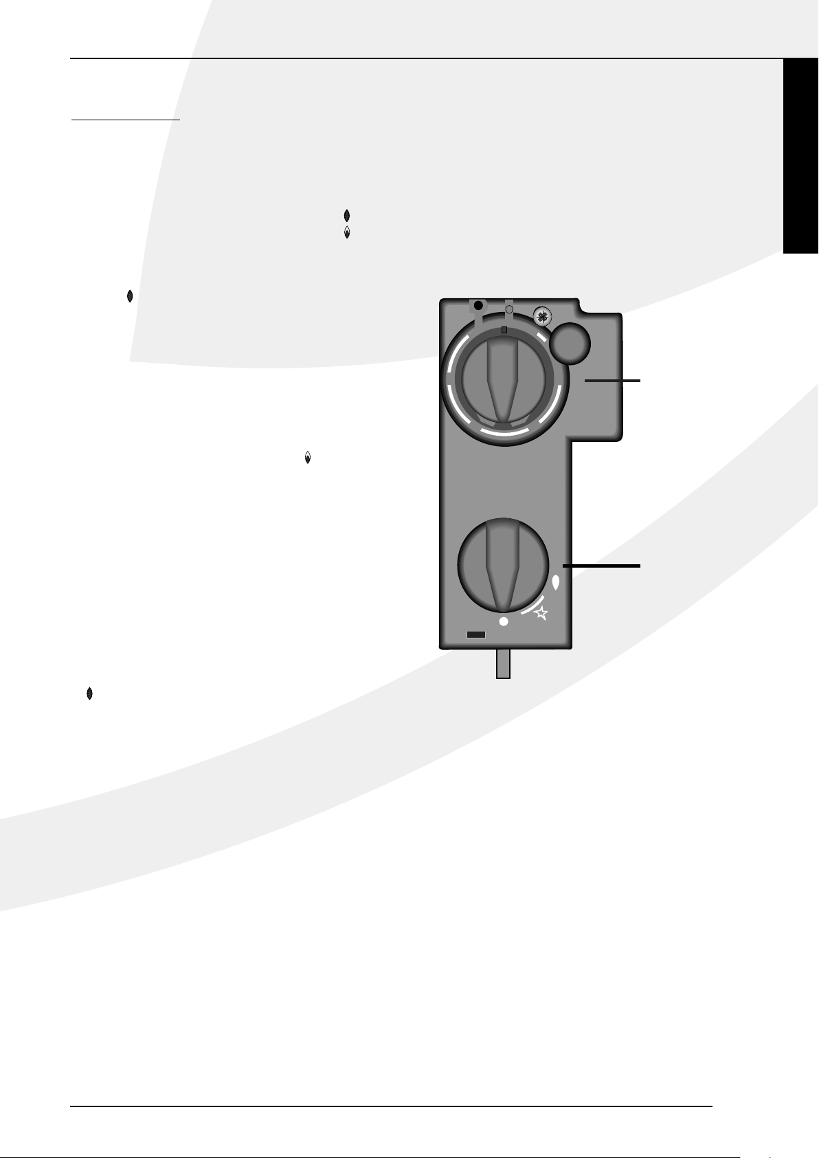
Ontsteken
De ontsteekknop A heeft drie standen namelijk:
O stand knop wijst naar O
Waakvlamstand knop wijst naar
Vol stand knop wijst naar
Draai de Ontsteekknop vanaf O stand linksom,
tevens goed indrukken en doordraaien naar de
waakvlamstand . Door het draaien aan de knop wordt
de waakvlambrander door een elektrische vonk ontstoken. Als de waakvlam brandt, de knop nog ca 10 sec.
ingedrukt houden en dan loslaten. De waakvlambrander
is zichtbaar aan de zijkant achter het glasraam. Als de
waakvlam niet in één keer ontsteekt, kan bovenstaande
handeling meteen herhaald worden door met ingedrukte
knop terug te draaien richting O en weer linksom richting
waakvlamstand. Na het loslaten van de ansteekknop moet
de waakvlam blijven branden. De aansteekknop vervolgens
verder draaien naar volstand . Afhankelijk van thermostaatknop B zal de hoofdbrander ontstoken worden.
Temperatuur regelen
De stand van de thermostaatknop B bepaalt de
temperatuur in de kamer. Stand 6 geeft de hoogste
temperatuur en stand 1 de laagste. De thermostaat regelt
modulerend tussen “volstand” en “kleinstand” van de
brander. De thermostaat houdt de kamer automatisch op
de gewenste ingestelde temperatuur.
Uitschakelen
Draai de ontsteekknop A terug naar de Waakvlamstand
(symbool
toestel volledig uit te zetten drukt u vervolgens knop A in
en draait hem terug naar stand O.
Belangrijk
Een ingebouwde veiligheidsvergrendeling treedt in werking
wanneer het toestel op ,,UIT” (stand O) wordt gezet.
Wacht daarom 5 minuten alvorens het toestel opnieuw
te ontsteken. Probeer binnen deze tijd niet de aansteekknop in te drukken, daar deze door de veiligheidsvergrendeling geblokkeerd is. Forceer de knop niet,
omdat het mechanisme dan kan worden beschadigd.
), alleen de waakvlam blijft branden. Om het
Bij deze set zit een ontvanger, plaats deze in het daarvoor
bestemde bakje.
Art 2-01: Het bakje bevindt zich links van het gasregelblok.
Art 3-01, 4-01, 5-01, 6-01, 8-02, 10-02: Het bakje bevindt
zich Onder het gasregelblok.
Voorkom dat de kabels tegen de hete delen van het binnenwerk aankomen.
1
2
6
5
B
3
4
A
38P-0744/0
Eco control pack
Voor dit toestel is een los verkrijgbare “Eco control pack”
met afstandsbediening beschikbaar. Het “Eco control pack”
is nodig om het optimale uit uw toestel te halen.
ART
5
Page 8

ALGEMENE OPMERKINGEN
ALGEMENE OPMERKINGEN
Art 2-01,3-01 en 4-01 op propaan (G31) zijn
plaatsbaar in mobiele wagens mits voldaan
wordt aan het volgende:
• Wanneer het toestel in bedrijf is moet de wagen stil staan;
• Wanneer het mobiele-wagen-trekkende voertuig wordt
gevuld met brandstof moet het toestel uit;
• Bij glas breuk schakel het toestel uit en neem contact
met een installateur op;
• Bij gaslek schakel het toestel uit en tevens de gas toe-
voer kraan en neem contact met een installateur op;
• Rookgasafvoer dient ten alle tijden vrij gehouden te worden.
Onderhoud en reiniging
Uw toestel dient eenmaal per jaar door een gekwalificeerd
bedrijf te worden gecontroleerd, en waar nodig, hersteld
of gereinigd. De controle en het onderhoud dient in ieder
geval een goede en veilige werking van het toestel te
omvatten. U kunt hiervoor gebruik maken van uw gasinstallateur of een gespecialiseerd onderhoudsbedrijf. Het
verdient aanbeveling om vóór en tijdens het stookseizoen
het toestel enkele malen stofvrij te maken. Bij het reinigen
van de mantel geen bijtende of schurende middelen gebrui
ken. Lakbeschadigingen, bijvoorbeeld door het plaatsen van
voorwerpen op of tegen de mantel, vallen buiten de garan
tie.
Eerste maal stoken
Tijdens de eerste maal stoken kan er een onaangename
geur ontstaan, die wordt veroorzaakt door het uitdampen
van de lak. Dit verdwijnt na enkele uren. Daarom raden
wij u aan het toestel de eerste maal op de hoogste stand
te stoken terwijl u tevens het vertrek waarin de kachel
staat goed ventileert.
Extra bescherming
Indien het toestel in een vertrek geïnstalleerd wordt waar
jonge kinderen of hulpbehoevende mensen zonder toezicht verblijven, is het wenselijk het toestel af te schermen.
Afdanken
Indien u het toestel vervangt of verwijdert, moet u het
toestel via de reguliere weg afvoeren. Voordat tot demontage wordt overgegaan eerst de aansluitkraan met koppeling dichtdraaien. De koppeling tussen aansluitkraan
en toestel losdraaien. Het gehele toestel kan nu worden
gedemonteerd en afgevoerd.
Garantie
De garantie op uw DRU toestel wordt verleend via uw
-
leverancier. In geval van storingen dient u altijd met hem
contact op te nemen. Uw leverancier zal DRU inschakelen
-
indien hij dit noodzakelijk acht. De fabrieksgarantie op uw
toestel bedraagt 2 jaar na datum van aankoop.
Let op: Bij het vervangen van het thermokoppel moet
de wartel in het gasregelblok handvast gedraaid worden,
waarna deze met een steeksleutel een kwartslag aangedraaid moet worden.
Verkleuring van wanden en plafonds
Bruinverkleuring is een vervelend probleem en is moeilijk
op te lossen. Bruinverkleuring kan worden veroorzaakt
door onder andere stofverbranding veroorzaakt door te
weinig ventilatie, door het roken van sigaretten of het
branden van kaarsen.
Deze problemen kunnen worden voorkomen door:
Het vertrek waar het toestel zich bevind goed te ventileren. Een goede richtlijn hiervoor is:
Bij nieuwbouw : 3.24 m3 / uur per m2
vloeroppervlak van een vertrek.
3
Bij bestaande bouw : 25.20 m
/ uur voor een vertrek.
Maak zo weinig mogelijk gebruik van kaarsen en olielampjes en houd het verbrandingslontje zo kort mogelijk. Deze
“sfeerbrengers” zorgen voor aanzienlijke hoeveelheden
vervuilde en ongezonde roetdeeltjes in uw woning. Rook
van sigaretten en sigaren bevat o.a. teerstoffen die bij
verhitting eveneens op koudere en vochtige muren zullen
neerslaan. Bij een nieuw gemetselde schouw of na een verbouwing wordt aanbevolen minimaal 6 weken te wachten
voordat men gaat stoken, het bouwvocht moet namelijk
geheel verdwenen zijn uit wanden, vloer en plafond.
6
Page 9

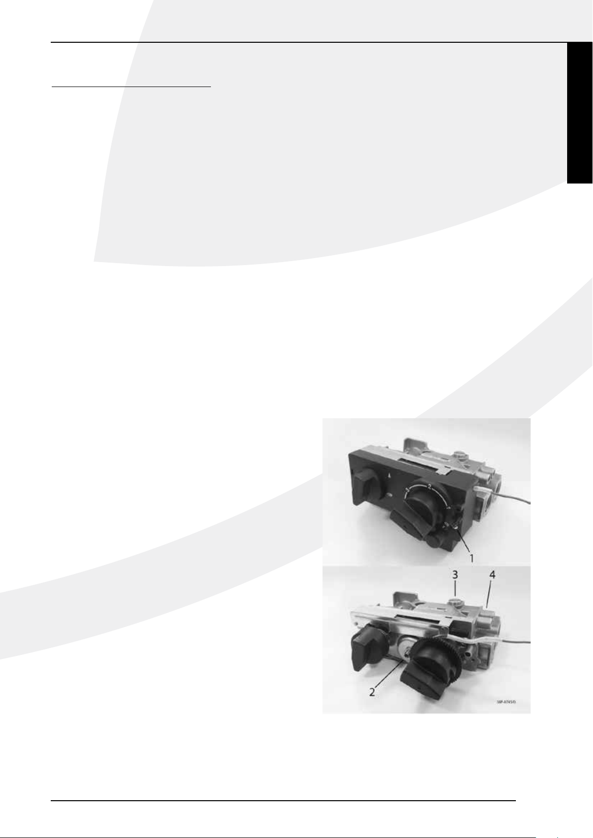
OMBOUWINSTRUCTIES
de branderdruk eenvoudig met een manometer
gecontroleerd kan worden. Draai de
drukmeetpuntschroef (4) los en sluit de
manometer aan.
Voor ombouw naar propaan of aardgas moet de
branderdruk met de drukregelschroef (2) worden
ingesteld, de branderdruk is te vinden in de
technische gegevens. Drukregelschroef (2) bevind
zich achter het kapje op het gasregelblok. Dit kapje
kan verwijderd worden door schroef (1) uit te
draaien en de lip aan de linkerzijde met behulp van
een schroevendraaier los te klikken.
Ontsteek de waakvlam. Zet de thermostaat op de
hoogste stand en stel de branderdruk. in volgens
de tabel. Zet de brander weer uit, verwijder de
manometer en draai drukmeet puntschroef weer
aan. Plaats het kapje weer terug op het
gasregelblok.
Art 2-01, 3-01, 4-01, 5-01, 6-01, 8-02, 10-02
9. Plak tenslotte de nieuwe typeplaat. Plaats de
mantel terug over het toestel.
Nederlands
OMBOUWINSTRUCTIES
De ombouw moet worden uitgevoerd door een erkende
installateur.
1. Sluit de gastoevoerleiding af.
2. Verwijder de mantel.
Wanneer de rechterkant van het toestel moeilijk bereikbaar
is:
3. Ontkoppel de gastoevoerleiding.
4. Haal het toestel van de wand.
Verwisselen van de onderdelen:
Art 2-01, 3-01, 4-01, 5-01, 6-01, 8-02, 10-02
5. Waakvlamspuitstuk
Draai de waakvlam-wartel aan het eind van de
waak-vlamleiding los, trek de waakvlam-leiding met
tonnetje uit de waak-vlambrander en verwijder het
waakvlamspuitstuk. Plaats nieuw waak-vlamspuitstuk en
draai de waakvlam-wartel van de waakvlamleiding stevig
aan.
Art 2-01
6. Hoofdbranderspuitstuk
Draai de wartel rond het spuitstuk los. Draai ook
de wartel in het gasregelblok enkele slagen los. Trek
vervolgens de toevoergasbuis uit het spuitstuk en draai
deze weg van het spuitstuk. Draai met een steeksleutel
het knietje en het spuitstuk uit de brander, verwijder het
spuitstuk uit het knietje en plaats het nieuwe spuitstuk.
Sluit tenslotte de onderdelen in omgekeerde volgorde
weer aan.
Art 3-01, 4-01, 5-01, 6-01, 8-02, 10-02
6. Hoofdbranderspuitstuk
Draai de wartel rond het spuitstuk los. Draai ook
de wartel in het gasregelblok enkele slagen los. Trek
vervolgens de toevoergasbuis uit het spuitstuk en draai
deze weg van het spuitstuk. Draai met een steeksleutel
het spuitstuk uit de brander en plaats het nieuwe
spuitstuk. Sluit tenslotte de onderdelen in omgekeerde
volgorde weer aan.
Art 2-01, 3-01, 4-01, 5-01, 6-01, 8-02, 10-02
8. Instellen van de branderdruk
Koppel de gastoevoerleiding weer aan het toestel en
open de gastoevoer van het nieuwe gas. Het gasregelblok
heeft een druk meetpunt, waarmee de branderdruk
eenvoudig met een manometer gecontroleerd kan
worden. Draai de drukmeetpuntschroef (4) los en sluit
de manometer aan.
Voor ombouw naar propaan of aardgas moet de
branderdruk met de drukregelschroef (2) worden
ingesteld, de branderdruk is te vinden in de technische
gegevens. Drukregelschroef (2) bevind zich achter het
kapje op het gasregelblok. Dit kapje kan verwijderd
worden door schroef (1) uit te draaien en de lip aan de
linkerzijde met behulp van een schroevendraaier los te
klikken.
Ontsteek de waakvlam. Zet de thermostaat op de
hoogste stand en stel de branderdruk. in volgens de
tabel. Zet de brander weer uit, verwijder de manometer
en draai drukmeet puntschroef weer aan. Plaats het kapje
weer terug op het gasregelblok.
Art 2-01, 3-01, 4-01, 5-01, 6-01, 8-02, 10-02
9. Plak tenslotte de nieuwe typeplaat. Plaats de mantel terug
over het toestel.
Art 2-01, 3-01, 4-01, 5-01, 6-01, 8-02, 10-02
7. Kleinstelspuitstuk
Indien nodig schroef het gasregelblok van het toestel.
Draai het kleinstelspuitstuk (3) uit het gasregelblok.
Plaats het nieuwe kleinstelspuitstuk en draai het goed
vast.
ART
7
Page 10

)
(
p
g)
TECHNISCHE GEGEVENS
input
(GCV)
mg/kWh
G20 G31 Eenheid
Art10‐02Art5‐01 Art6‐01 Art8‐02
G25/
G25.3*
G20 G31
G25/
G25.3*
G20 G31
G25/
G25.3*
G20 G31
G25/
G25.3*
Ja
G20 G31
G25/
G25.3*
Nee
Nee
Ja**
Ja**
Ja**Metelektronischesturingvandekamertemperatuurplusdag‐tijdschakelaar
Ja**
Ja**
Ja**Metdeoptievanafstandsbediening
G20 G31
G25/
G25.3*
G20 G31
Art2‐01 Art3‐01 Art4‐01
‐‐‐‐‐‐‐‐‐‐‐‐‐‐‐‐‐‐‐‐‐ kW
‐‐‐‐‐‐‐‐‐‐‐‐‐‐‐‐‐‐‐‐‐ kW
‐‐‐‐‐‐‐‐‐‐‐‐‐‐‐‐‐‐‐‐‐ kW
G25/
G25.3*
102,9 102,7 92,6 99,9 109,9 108,9 118,0 123,0 129,7 88,4 103,2 109,8 81,4 94,6 99,2 95,2 105,9 125,5 102,6 113,8 129,7
x
2,1 2,3 2,0 2,8 3,0 3,4 3,5 3,8 3,8 4,5 4,8 5,1 5,3 5,6 5,7 8,5 9,0 9,2 9,8 10,5 9,9 kW
P
nom
0,5 0,5 0,7 0,9 0,9 1,0 1,0 1,1 0,9 1,1 1,1 1,3 1,2 1,2 1,3 1,8 1,9 1,9 2,4 2,6 3,1 kW
P
81,7 83,4 82,0 83,0 84,1 85,9 83,0 83,9 83,9 87,5 89,1 88,7 87,2 88,0 88,0 90,6 91,1 91,1 87,9 88,4 88,4 %
74,1 75,1 76,6 78,3 78,8 78,5 72,9 75,9 71,5 84,1 84,1 84,3 82,6 81,9 82,2 87,9 88,3 88,5 83,2 84,0 83,5 %
min
th,nom
η
th,min
η
max
el
el
‐‐‐‐‐‐‐‐‐‐‐‐‐‐‐‐‐‐‐‐‐ kW
SB
min
pilot
el
P
Sturingvandekamertemperatuur,metaanwezigheidsdetec�e
Sturingvandekamertemperatuur,metopenraamdetec�e
Anderesturingsopties
assin
Typewarmteafgifte/sturingkamertemperatuur
Metelektronischesturingvandekamertemperatuur
Eentrapswarmteafgifte,geensturingvandekamertemperatuur
Typeaanduiding(en):
Gassoort: Symbool
Directewarmteafgifte 2,1 2,3 2,0 2,8 3,0 3,4 3,5 3,8 3,8 4,5 4,8 5,1 5,3 5,6 5,7 8,5 9,0 9,2 9,8 10,5 9,9 kW
Indirecteverwarmingsfunctionaliteit Nee Nee Nee Nee Nee Nee Nee Nee Nee Nee Nee Nee Nee Nee Nee Nee Nee Nee Nee Nee Nee
Indirectewarmteafgifte ‐‐‐‐‐‐‐‐‐‐‐‐‐‐‐‐‐‐‐‐‐ kW
Warmteafgifte
UitstootbijruimteverwarmingNo
Nominalewarmteafgifte
Minimalewarmteafgifte(indicatief)
TECHNISCHE GEGEVENS
Technischegegevens
Nominalebelasting(Hs) 2,8 3,0 2,6 3,7 3,9 4,3 4,8 5,0 4,9 5,7 6,0 6,2 6,8 7,1 7,1 10,4 11,0 11,0 12,4 13,1 12,2 kW
Nominalebelasting(Hi) 2,5 2,7 2,4 3,3 3,5 4,0 4,3 4,5 4,5 5,1 5,4 5,7 6,1 6,4 6,5 9,4 9,9 10,1 11,2 11,8 11,2 kW
indicatief
Branderspuitstuk 1,40 1,40 0,85 1,65 1,65 0,55 1,70 1,70 1,20 1,90 1,90 1,40 2,00 2,00 1,40 2,45 2,45 1,80 2,80 2,80 1,90 mm
Branderdrukvolstand 15,4 12,5 27,3 12,5 10,0 22,0 19,2 15,2 25,5 18,1 14,3 21,5 19,5 15,6 27,9 21,3 17,1 24,5 16,8 13,4 24,5 mbar
Kleinstelspuitstuk 0,50 0,50 0,40 0,80 0,80 0,55 0,90 0,90 0,55 0,85 0,85 0,65 0,90 0,90 0,65 1,15 1,15 0,80 1,35 1,35 1,05 mm
Branderdrukkleinstand 0,5 0,5 2,6 1,1 0,9 1,8 1,5 1,3 1,5 0,9 0,7 1,2 0,9 0,8 1,4 0,9 0,8 1,0 1,1 0,8 2,4 mbar
Nuttigrendement(NCV)
Rendementsklasse(EN613) 111111111111111111111
Gasverbruikvolstand 303 280 95 396 370 158 504 467 180 606 566 228 728 671 263 1122 1040 402 1317 1231 447 l/h
Gasverbruikkleinstand 74 70 36 133 121 52 160 147 48 145 136 61 168 155 64 245 227 87 340 315 145 l/h
Instand‐bymodus
Bijminimalewarmteafgifte
Bijnominalewarmteafgifte
Energie‐efficiëntie
indienvantoe
Energie‐efficiëntie‐index EEI 82 83 85 83 84 86 83 84 84 88 89 89 87 88 88 91 91 91 88 88 88
Energie‐efficiëntieklasse BBBBBBBBBAAABAAAAAAAA
Aanvullendelektriciteitsverbruik
Nuttigrendementbijminimalewarmteafgifte
Nuttigrendementbijnominalewarmteafgifte
Vermogenseisvoordepermanentewaakvlam
Vermogenseisvoordepermanentewaakvlam
Metmechanischesturingvandekamertemperatuurdoorthermostaat
Metelektronischesturingvandekamertemperatuurplusweek‐tijdschakelaar
Tweeofmeerhandmatigintestellentrappen,geensturingvandekamertemperatuur
*DittoestelisgeschiktvoorG25.3metdesamenstellingvolgensNTA8837.
**DezefunctieszijnalleenvantoepassingincombinatiemethetlosverkrijgbareEcocontrolpack.
8
Page 11

CONTENTS
CONTENTS
English
Foreword .............................................................................10
Unpacking .............................................................................10
Connection ..........................................................................10
Instructions for installation ..............................................10
Type of gas ...........................................................................10
Important .............................................................................10
General .................................................................................10
Installing to a wall of non-flammable material .............10
The standard wall duct .....................................................10
Installation of the standard exterior wall duct ...........10
The exterior wall duct with telescopic inlet pipe ......11
Installation of the wall duct with
telescopic inlet pipe ...........................................................11
Fastening the mounting sheet .........................................11
Installation to a wall of inflammable material ..............11
Connection of the gas supply ........................................11
Operations ...........................................................................12
The low setting ...................................................................12
Pilot light burner ................................................................12
Placing the housing .............................................................12
User manual .........................................................................13
Ignition ..................................................................................13
Controlling the temperature ...........................................13
Switching off ........................................................................13
Important .............................................................................13
Eco control pack ................................................................13
General notes .....................................................................14
Gas safety regulations (for installation & use), 1998 .14
Cleaning and Maintenance................................................14
Discoloration of walls and ceiling ..................................14
Lighting the heater for the first time.............................14
Extra protection .................................................................14
Disposal ................................................................................14
Guarantee ............................................................................14
Conversion insructions .....................................................15
Technical data .....................................................................16
CE-DECLARATION
We hereby declare that the design and construction of DRU’s gas-fired heating appliance comply with theessential
requirements of the Gas Appliance Directive.
Product: gas-fired heating appliance
Type: Art 2-01, 3-01, 4-01, 5-01, 6-01, 8-02, 10-02
EEC directives: 2009/142/EC
Standards: NEN-EN-613 NEN-EN-613/AI
Internal precautions at the company will guarantee that appliances produced in series comply with the essential
requirements of the EC directives in force and the standards derived from them. This declaration will lose its validity if
adjustments are made to the appliance without prior written permission by DRU. A copy of the test certificate can be
downloaded via www.druservice.com.
General manager
Postbus 1021, 6920 BA Duiven
Ratio 8, 6921 RW Duiven
www.dru.nl
ART
9
Page 12

INSTRUCTIONS FOR INSTALLATION
Foreword
Dear Customer,
We would like to thank you for buying this DRU product. Our products have been designed and produced to
meet the highest possible quality, performance and safety
requirements, allowing you to enjoy years of problem-free
use.
In this booklet you will find instructions for the installation
and use of your new appliance. Please read these instructions and the manual carefully to familiarize yourself with
the appliance. If you require any further support, please do
not hesitate to contact your supplier.
Unpacking
Once the heater has been unpacked, all packaging should
be disposed of in the regular manner.
Connection
This appliance should be connected by a registered installer.
INSTRUCTIONS FOR INSTALLATION
Art 2-01,3-01 and 4-01 on propane (G31) can be placed
in vehicles pulling mobile units, provided the following is
observed:
• When the appliance is working, the mobile unit must be
standing still;
• When the vehicle pulling the mobile unit is being filled
with fuel, the appliance must be switched off;
• If glass is broken, switch off the appliance and contact an
installer;
• In case of a gas leak, switch off the appliance as well as the
gas supply tap and contact an installer;
• Flue gas discharge must remain unobstructed at all times.
Installation to a wall of non-flammable material
(fig. 7, 9, 11, pg. 50-52)
ART Models 2-01, 3-01 and 4-01 can are suitable for
hanging installation only, ART Models 5-01, 6-01, 8-02
and 10-02 are suitable for either hanging or freestanding
installation. Allow at least 1 metre’s clearance above the
heater to enable sufficient heat circulation. When installed
hanging, at least 1 m free space should be kept above the
appliance to allow sufficient heat dissipation.
When intalled standing, the bottom of the mounting sheet
(2) should stand on the floor, this is the minimum height
between the floor and centre of wall duct
(size F. fig 7, 9, 11, pg. 50-52).
Type of gas
This appliance can only be used and is only suitable for the
country and the type of gas mentioned on the type identification tag. Please check that the local gas and pressure
correspond with the specifications on the type identification tag. All regulations regarding gas installation, including
any local regulations, must be observed at all times. The
appliance is to be installed by a competend person.
To operate the heater suitable for natural gas on propane,
it should be converted by a competend person. A conversion set can be ordered through your
supplier.
Important
• Keep curtains and any other flammable materials at least
50cm away form the appliance.
• Caution! Touching the heater when hot can cause burns
and blisters!
• The appliance should be installed and maintained by a
registered installer.
• Do not install any so-called dust filter on or under the
casing.
• Do not hang wet clothes and towels etc. on the heater to
dry.
General
The appliance can be mounted either on a wall of incombustible material (e.g. stone or concrete) or on a wall of combustible material (e.g. wood).
The mounting plate (2) serves as a template to mark the
position of the duct. To be able to hang the casing over the
interior, a minimal clearance of 25 mm must be allowed
between the appliance and a windowsill or suchlike. The
minimum clear installation height (Y) required for each of
the various models is listed in the table on page 53.
The standard wall duct
Drill a horizontal hole in the wall, ø E to take the air-supply
pipe. The wall duct should slope at an angle of approx. 2º.
The standard wall duct is suitable for walls with a thickness of 50 – 330 mm and the standard extended wall duct
for walls with a thickness of 50 – 600 mm. Depending on
the thickness of the wall, the inlet and outlet pipes should
be made to length, i.e.:
ART 2-01 Thickness of wall + 20mm Thickness of wall + 40mm
ART 3-01, 4-01 Thickness of wall + 20mm Thickness of wall + 30mm
ART 5-01, 6-01 Thickness of wall + 20mm Thickness of wall + 70mm
ART 8-02,10-02 Thickness of wall + 20mm Thickness of wall + 35mm
Length of inlet pipe Length of outlet pipe
The tension members fixed to the wall grid can be made
to size after installation
Installation of the standard exterior wall duct
(fig. 1, 3, 5, page 49/50)
Slide the adjusted inlet pipe (1) through the mounting
sheet (2), with the turned-back edge facing the mark (45º
top left) in the mounting sheet. Slide the sealing ring (3)
and the wall ring (4) around the inlet pipe, paying
10
Page 13

INSTRUCTIONS FOR INSTALLATION
attention to the order (see figure). Take the whole
and slide the inlet pipe into the wall opening. Press the
mounting sheet up to the wall. Press the inlet pipe back
in such a way that the end of the pipe is level with the
turned-back edge of the mounting sheet.
From the outside, bring the wall grid with its attached
tension members into the inlet pipe. Bend the tension
members a little outwards, so that they will jam slightly
in the inlet pipe, keeping the grid in its place. Keep the
mark “Top” up when placing the wall grid. Slide the two
fastening clamps (5) over the tension members (6), taking
care that the fastening clamps catch on the turned-back
edge of the mounting sheet. Fix the screw-nuts onto the
tension members and tighten them by hand. Place the fastening clamps onto the horizontal centre line of the inlet
pipe. See also the marks in the mounting sheet.
The exterior wall duct with telescopic inlet
pipe
This is suitable for wall thicknesses of 250 – 440 mm
without shortening the parts of the inlet pipe. By shortening the pipe’s parts, this exterior wall duct can be
adapted for thicknesses of 70 – 250 mm. The outlet pipe
should be adjusted. The tension members attached to
the wall grid can be shortened after the wall duct has
been mounted. If the telescopic inlet pipe is applied for
wall thicknesses of 70 – 250 mm, both parts of the pipe
should be shortened, i.e.:
• the part of the inlet pipe on the side of the wall grid
equal to the thickness of the wall
• the part of the pipe on the side of the heater to a length
equalling the wall thickness minus 20 mm.
Fastening the mounting sheet
(fig. 1, 3, 5, page 49/50)
Caution: Level the mounting sheet, make sure that the
inlet pipe goes down towards the outside. (1 cm to 1 m)
and that the wall grid lies straight against the exterior
wall. Then, any condensation will never get into the
heater because of the downwards flow of the pipe.
• Now tighten the screw nuts on the tension members
• Saw or cut the tension members so that they do not
stick out from the fastening clamps (5).
• Drill the hole for the key bolt (7).
• Attach the key bolt and attach the mounting sheet using
the bolt (8) and washer (9).
Installation to a wall of inflammable material
(fig. 8, 10, 12, page 51/52)
When the appliance is installed to a wall of flammable
material, the wall duct should be executed as follows.
• On the spot of the duct, create a square opening in the
wall (
M mm).
• In the case of compressible walls, fill up the space all
round the opening well, so that the wall cannot be
crushed.
• In addition, replace the bolt (8) by e.g. a wood screwed
bolt.
• On the room side, put the heat shield (14) between the
mounting sheet (2) and the wall.
• On the outside of the wall, using 4 screws (16), attach
siluminplate (15).
The heat shield (14) and the silumin plate (15) are packed
together and are available from your dealer. Assembling
the wall duct is otherwise the same as previously
described.
English
CAUTION: do not cut the pipe parts on the side
where the fastening clamps have been applied.
Installation of the wall duct with telescopic
inlet pipe (fig. 1, 3, 5, page 49/50)
From the outside, put the wall grid, together with the
attached half inlet pipe into the created wall opening,
keeping “Top” up when placing the wall grid. Slide the
other half of the inlet pipe through the mounting sheet
(2), making sure that the inserted fastening clamps (5)
lie on the horizontal centre line (see the marks in the
mounting sheet). They should catch on the turned-back
edge of the mounting sheet.
Attach the sealing ring (3) and the wall ring (4) to the
half inlet pipe (see ffigure for the correct order). Take
the whole and, from the inside, slide the half inlet pipe
through the created wall opening into the part of the
inlet pipe already mounted. While doing so, make sure
the the two tension members (6) stick through the fastening clamps. Press the mounting sheet up to the wall.
Appply the screw-nuts onto the tension members (6) and
tighten them by hand against the fastening clamps (5).
N.B. To calculate the length of the inlet and outlet pipe,
the thickness of siluminplate (15) should be included.
Installation of the interior
(fig.2, 4, 6, page 49/50)
Slide the adjusted outlet pipe into the grid opening. Slide
the two Silicon Rubber Tulles (packed with the glass silk
rope) over the bolts (10) and into the holes of the back
plate.
This prevents possible dirt and deposit from settling onto
the wall. Take the interior and put it with the bottom
edge on the two supports of the mounting sheet. Keep
the interior balanced and slide the outlet pipe a little bit
into the outlet opening of the interior for support. Now
slide the interior against the mounting sheet, taking care
that the turned-back edge of the mounting sheet fits
into the inlet bush on the back side of the interior and
that the bolts (10) stick through the clamps (11). Attach
screw nuts and washers to the bolts (10) and tighten
closely up to the stop. Then slide the screw spindle (12)
into the clamp (13). Fix the screw nut and washer to the
screw spindle (12) and tighten until the interior is standing parallel to the wall.
11
ART
Page 14

INSTRUCTIONS FOR INSTALLATION
N.B. If easy accessible, e.g. on the ground floor, the outlet
pipe can also be mounted from the outside after the grid
interior sheet and the basket have been disassembled.
ART 3-01 and 4-01:
After fitting heat-exchanger fix thermostat phial in clip
provided at rear of backplat (R.H.S.).
Connection of the gas supply
For the different types are the connections as mentioned
below:
• ART 2-01, 5-01, 6,-01, 8-02, 10-02 3/8” inner thread
• ART 3-01, 4-01 3/8” outer thread
If the supply pipe enters the appliance through the back
plate, press out the disc in the plate. An approved connecting tap with coupling should be used in the supply
pipe (For Belgium this should be B.G.V. approved). The
connecting tap with coupling should be fitted outside the
casing. Furthermore:
• Expel all air from the supply pipes/hoses before coupling
to the appliance.
• Do not turn the coupling tap when connecting it to the
gas supply.
• Avoid any pressure on the control tap and pipes.
• Check that all connections are gastight.
Operations
The manufacturer has made the appliance suitable for the
type of gas as indicated on the type identification tag. The
thermostat regulates modulatingly between “full power
setting” and “low power setting” and , when little heat is
required, in two settings, i.e. “low” or “off”. In this situation, the pilot light keeps burning. The “low” setting can
only be checked when the room temperature is higher
than
± 15°C (60°F).
The low setting
The low setting has been adjusted to ± 20% of the full
consumption. The low setting screw has been fully tightened and is supplied with the correct low setting bore.
This is not adjustable.
Pilot light burner
Upon delivery, the pilot light burner has the correct consumption by means of a nozzle inside the pilot light burner.
The pilot light burner needs no adjustment.
Putting the casing in its place
From the top, hang the casing over the back sheet, taking
care that the hooks of the casing fit into the notches of
the back sheet and that the operating buttons fit into the
appropriate opening in the casing.
12
Page 15
USER MANUAL
control pack” is needed to get the best out of your
appliance.
This set has a receiver that must be placed in the
tray specifically intended for this purpose.
Art 2-01: The tray is located on the left side of the
gas control.
Art 3-01, 4-01, 5-01, 6-01, 8-02, 10-02: The tray is
located under the gas control.
Prevent cables from making contact with hot
internal components.
USER MANUAL
Ignition
Ignition button A has three positions, i.e.:
O position button points to O
Pilot burner position button points to
Full position button points to
Turn the ignition button to the left from position O, press
down firmly as well and keep turning to the pilot burner
position
ted by means of an electrical spark. When the pilot burner
burns, keep pressing down the button for approx. 10 sec.
and then let go. The pilot burner is visible from the side,
behind the glass window. If the pilot burner does not
ignite at once, the above-mentioned action can be repeated immediately by turning the pressed down button back
towards O and then left again towards the pilot burner
position. After letting go of the ignition button, the pilot
burner should continue to burn. Then turn the ignition
button further towards the full position
thermostat button B, the main burner will be ignited.
. By turning the button, the pilot burner is igni-
. Depending on
This set has a receiver that must be placed in the tray
specifically intended for this purpose.
Art 2-01: The tray is located on the left side of the gas
control.
Art 3-01, 4-01, 5-01, 6-01, 8-02, 10-02: The tray is located
under the gas control.
Prevent cables from making contact with hot internal
components.
1
2
6
5
B
3
4
English
Controlling the temperature
The position of thermostat button B determines the
temperature in the room. Position 6 provides the highest
temperature, position 1 the lowest. The thermostat
controls the burner by modulating between “full position”
and “low position” of the burner. The thermostat will
automatically keep the room at the required set
temperature.
Switching off
Turn ignition button A back to the Pilot Burner position
(
symbol), only the pilot burner will continue to burn.
In order to switch off the appliance fully, you must press
down button A and turn it back to position O.
Important
An incorporated safety lock will be activated if the appliance is set to the ,,OFF” (O) position. Therefore, wait
5 minutes before re-igniting the appliance. Do not try
to press down the ignition button during this time, as it is
locked by means of the safety lock. Do not force the
button, because the mechanism could get damaged.
Eco control pack
It is possible to order a separately available “Eco control
pack” with remote control. The “Eco control pack” is
needed to get the best out of your appliance.
A
38P-0744/0
13
ART
Page 16

GENERAL NOTES
GENERAL NOTES
Art 2-01,3-01 and 4-01 on propane (G31) can
be placed in vehicles pulling mobile units, provided the following is observed:
• When the appliance is working, the mobile unit must be
standing still;
• When the vehicle pulling the mobile unit is being filled
with fuel, the appliance must be switched off;
• If glass is broken, switch off the appliance and contact an
installer;
• In case of a gas leak, switch off the appliance as well as the
gas supply tap and contact an installer;
• Flue gas discharge must remain unobstructed at all times.
Gas Safety Regulations (for installation & use) 1998
In your own interest and that of safety, it is law that all gas
appliances are installed by competent persons in accordance with the above regulations. Failure to install appliances correctly could lead to prosecution.
NB: The Confederation of Registered Gas Installers,
whose members are identified by the emblem shown here,
are all required to work to the recognised standards.
Cleaning and Maintenance
The appliance should be inspected once a year by a qualified company, and cleaned and/or repaired as necessary.
The inspection and maintenance must at least ensure that
the appliance is working correctly and safely. This can be
done by your own gasinstaller or a specialised maintenance company. It is advisable to remove any dust from
the appliance several times before and during the heating
season. Do not use corrosive or abrasive substances to
clean the casing. Any damage to the coating, caused by
things put on or against the casing for example, is not covered by the guarantee.
NB: When replacing the pilot light burner, the coupling
nut in the gas control block should first be tightened by
hand and then tightened a quarter-turn with an
open-ended spanner.
ing will precipitate on cold or damp walls. If you have a
newly cemented chimney or have had any other reconstructions / renovations done, you are advised to wait at
least 6 weeks before lighting your fire, to allow the walls,
floor and ceiling to dry out completely.
Lighting the heater for the first time
There can be an unpleasant smell when you light the heater for the first time. This is caused by the varnish evaporating and will disappear after a few hours. We therefore
advise you, on initial use, to heat the appliance at the highest setting while ventilating the room it is installed in well.
Extra protection
This heater meets the normal safety standards regarding
surface temperatures, but physical contact with heated
surfaces should be avoided where possible. An additional
guard is recommended to protect young children and
elderly, infirmed or handicapped people.
Disposal
When replacing or otherwise removing the appliance, it
should be disposed of in compliance with current regulations.
Shut off the connecting tap with coupling before commencing disassembly. Undo the coupling between the
connecting tap and the appliance. The whole appliance can
now be disassembled and removed.
Guarantee
The warranty for your DRU appliance will be provided by
your supplier. In case of malfunctions, you should always
contact him. You supplier will contact DRU if he feels this
is necessary. The factory warranty for your appliance is
valid for 2 years after date of purchase.
Discoloration of walls and ceiling
Brown discoloration is an annoying problem, which is difficult to solve. It can be caused by dust burning as a result
of poor ventilation, for example, or by cigarette smoke or
candles.
These problems can be avoided by ensuring that the room
the heater is in is properly ventilated. A good guideline for
ventilation is:
New buildings : 3.24 m
3
/ hour per m2 floor
surface of the room.
Existing buildings : 25.20 m3 / hour for a room.
Use candles and oil lamps as little as possible, keeping the
wick as short as possible. While they enhance the atmosphere, candles and oil lamps also cause the formation of
large quantities of unhealthy soot particles in your home.
Cigarette and cigar smoke contains tar, which upon heat-
14
Page 17
CONVERSION INSTRUCTIONS
de branderdruk eenvoudig met een manometer
gecontroleerd kan worden. Draai de
drukmeetpuntschroef (4) los en sluit de
manometer aan.
Voor ombouw naar propaan of aardgas moet de
branderdruk met de drukregelschroef (2) worden
ingesteld, de branderdruk is te vinden in de
technische gegevens. Drukregelschroef (2) bevind
zich achter het kapje op het gasregelblok. Dit kapje
kan verwijderd worden door schroef (1) uit te
draaien en de lip aan de linkerzijde met behulp van
een schroevendraaier los te klikken.
Ontsteek de waakvlam. Zet de thermostaat op de
hoogste stand en stel de branderdruk. in volgens
de tabel. Zet de brander weer uit, verwijder de
manometer en draai drukmeet puntschroef weer
aan. Plaats het kapje weer terug op het
gasregelblok.
Art 2-01, 3-01, 4-01, 5-01, 6-01, 8-02, 10-02
9. Plak tenslotte de nieuwe typeplaat. Plaats de
mantel terug over het toestel.
CONVERSION INSTRUCTIONS
The conversion should be performed by a recognised
installer.
1. Close the gas supply pipe.
2. Remove the mantelpiece.
If the right side of the appliance is difficult to reach:
3. Disconnect the gas supply pipe.
4. Move the appliance away from the wall.
Changing the parts:
Art 2-01, 3-01, 4-01, 5-01, 6-01, 8-02, 10-02
5. Pilot burner injector.
Loosen the pilot burner gland nut at the end of the pilot
burner pipe, pull the pilot burner with catch out of the
pilot burner and remove the pilot burner injector. Place
new pilot burner injector and firmly tighten the pilot
burner gland nut of the pilot burner pipe.
Art 2-01
6. Main burner injector
Loosen the gland nut around the injector. Also loosen
the gland nut in the gas control by a few turns. Then pull
the supply gas pipe out of the injector and turn it away
from the injector. Use an open-end wrench to unscrew
the
knee-piece and injector out of the burner, remove the
injector from the knee-piece and place the new injector.
Finally, reconnect the parts in reverse order.
Art 3-01, 4-01, 5-01, 6-01, 8-02, 10-02
6. Main burner injector
Loosen the gland nut around the injector. Also loosen
the gland nut in the gas control by a few turns. Then pull
the supply gas pipe out of the injector and turn it away
from the injector. Use an open-end wrench to unscrew
the injector from the burner and place the new injector.
Finally, reconnect the parts in reverse order.
Art 2-01, 3-01, 4-01, 5-01, 6-01, 8-02, 10-02
English
8. Setting the burner pressure
Reconnect the gas supply pipe to the appliance and open
the supply of new gas. The gas control has a pressure
gauge point, making it easy to check the burner pressure
by means of a manometer. Loosen the pressure gauge
point screw (4) and connect the manometer.
For conversion to propane or natural gas, the burner
pressure must be set by means of the pressure control
screw (2), the burner pressure can be found in the
technical information. The pressure control screw (2) is
located behind the cover of the gas control. This cover
can be removed by removing screw (1) and clicking loose
the lip on the left side by means of a screwdriver.
Ignite the pilot burner. Set the thermostat to the highest
setting and adjust the burner pressure in accordance
with the table. Turn off the burner again, remove the
manometer and tighten the pressure gauge point screw.
Place the cover back on the gas control.
Art 2-01, 3-01, 4-01, 5-01, 6-01, 8-02, 10-02
9. Finally, attach the new type plate. Place the mantelpiece
back over the appliance.
Art 2-01, 3-01, 4-01, 5-01, 6-01, 8-02, 10-02
7. Low setting injector
If necessary, unscrew the gas control from the appliance.
Unscrew the low setting injector (3) from the gas
control. Place the new low setting injector and tighten
firmly.
ART
15
Page 18

)
TECHNICAL DATA
G20 G31 Unit
Art10‐02Art3‐01 Art4‐01Art2‐01 Art5‐01 Art6‐01 Art8‐02
G25/
G25.3*
G20 G31
G25/
G25.3*
G20 G31
G25/
G25.3*
input
(GCV)
mg/kWh
G20 G31
G25/
G25.3*
G20 G31
G25/
G25.3*
G20 G31
G25/
G25.3*
G20 G31
G25/
G25.3*
102,9 102,7 92,6 99,9 109,9 108,9 118,0 123,0 129,7 88,4 103,2 109,8 81,4 94,6 99,2 95,2 105,9 125,5 102,6 113,8 129,7
x
Gastype: Symbol
Modelidentifier(s):
Directheatoutput 2,1 2,3 2,0 2,8 3,0 3,4 3,5 3,8 3,8 4,5 4,8 5,1 5,3 5,6 5,7 8,5 9,0 9,2 9,8 10,5 9,9 kW
Indirectheatoutput ‐‐‐‐‐‐‐‐‐‐‐‐‐‐‐‐‐‐‐‐‐ kW
Indirectheatingfunctionality No No No No No No No No No No No No No No No No No No No No No
SpaceheatingemissionsNO
TECHNICAL DATA
2,1 2,3 2,0 2,8 3,0 3,4 3,5 3,8 3,8 4,5 4,8 5,1 5,3 5,6 5,7 8,5 9,0 9,2 9,8 10,5 9,9 kW
nom
P
Heatoutput
Nominalheatoutput
0,5 0,5 0,7 0,9 0,9 1,0 1,0 1,1 0,9 1,1 1,1 1,3 1,2 1,2 1,3 1,8 1,9 1,9 2,4 2,6 3,1 kW
min
P
Technicaldata
Nominalheatinput(Hs) 2,8 3,0 2,6 3,7 3,9 4,3 4,8 5,0 4,9 5,7 6,0 6,2 6,8 7,1 7,1 10,4 11,0 11,0 12,4 13,1 12,2 kW
Minimumheatoutput(indicative)
Nominalheatinput(Hi) 2,5 2,7 2,4 3,3 3,5 4,0 4,3 4,5 4,5 5,1 5,4 5,7 6,1 6,4 6,5 9,4 9,9 10,1 11,2 11,8 11,2 kW
No
No
81,7 83,4 82,0 83,0 84,1 85,9 83,0 83,9 83,9 87,5 89,1 88,7 87,2 88,0 88,0 90,6 91,1 91,1 87,9 88,4 88,4 %
th,nom
η
74,1 75,1 76,6 78,3 78,8 78,5 72,9 75,9 71,5 84,1 84,1 84,3 82,6 81,9 82,2 87,9 88,3 88,5 83,2 84,0 83,5 %
th,min
η
‐‐‐‐‐‐‐‐‐‐‐‐‐‐‐‐‐‐‐‐‐ kW
el
Yes
Yes**
‐‐‐‐‐‐‐‐‐‐‐‐‐‐‐‐‐‐‐‐‐ kW
‐‐‐‐‐‐‐‐‐‐‐‐‐‐‐‐‐‐‐‐‐ kW
‐‐‐‐‐‐‐‐‐‐‐‐‐‐‐‐‐‐‐‐‐ kW
SB
min
max
el
pilot
el
P
Yes**
Yes**
Yes**
Yes**
Withdistancecontroleoption
Withelectronicroomtemperaturecontrol
Typeofheatoutput/roomtemperaturecontrol
Singlestageheatoutput,noroomtemperaturecontrol
Withmechanicthermostatroomtemperaturecontrol
Twoormoremanualstages,noroomtemperaturecontrol
Withelectronicroomtemperaturecontrolplusdaytimer
Withelectronicroomtemperaturecontrolplusweektimer Yes**
Roomtemperaturecontrol,withpresencedetection
Othercontroloptions(multipleselectionspossible)
Roomtemperaturecontrol,withopenwindowdetection
indicative
Instandbymode
Consumptionmin 74 70 36 133 121 52 160 147 48 145 136 61 168 155 64 245 227 87 340 315 145 l/h
Consumptionmax 303 280 95 396 370 158 504 467 180 606 566 228 728 671 263 1122 1040 402 1317 1231 447 l/h
Burnerpressuremax 15,4 12,5 27,3 12,5 10,0 22,0 19,2 15,2 25,5 18,1 14,3 21,5 19,5 15,6 27,9 21,3 17,1 24,5 16,8 13,4 24,5 mbar
Lowsettinginjector 0,50 0,50 0,40 0,80 0,80 0,55 0,90 0,90 0,55 0,85 0,85 0,65 0,90 0,90 0,65 1,15 1,15 0,80 1,35 1,35 1,05 mm
Burnerpressuremin 0,5 0,5 2,6 1,1 0,9 1,8 1,5 1,3 1,5 0,9 0,7 1,2 0,9 0,8 1,4 0,9 0,8 1,0 1,1 0,8 2,4 mbar
Mainburnerinjector 1,40 1,40 0,85 1,65 1,65 0,55 1,70 1,70 1,20 1,90 1,90 1,40 2,00 2,00 1,40 2,45 2,45 1,80 2,80 2,80 1,90 mm
Efficiencyclass(EN613) 111111111111111111111
Usefulefficiency(NCV)
Atnominalheatoutput
Atnominalheatoutput
Energyefficiency
Energyefficiencyindex EEI 82 83 85 83 84 86 83 84 84 88 89 89 87 88 88 91 91 91 88 88 88
Energyefficiencyclass BBBBBBBBBAAABAAAAAAAA
Auxiliaryelectricityconsumption
Usefulefficiencyatnominalheatoutput
Usefulefficiencyatminimumheatoutput
Permanentpilotflamepowerrequirement
Pilotflamepowerrequirement(ifapplicable)
*ThisapplianceissuitableforG25.3withthecompositionaccordingNTA8837.
**Thesefunctionsonlyapplyincombinationwiththeseparatelyavailable"Ecocontrolpack".
16
Page 19

INHALT
INHALT
Deutsch
Einige kurze Worte ...........................................................18
Auspacken ............................................................................18
Anschluss ..............................................................................18
Installationsvorschrift ........................................................18
Gassorte ...............................................................................18
Wichtig .................................................................................18
Allgemein ..............................................................................18
Installation an eine Wand von nicht brennbarem
Material .................................................................................18
Giebeldurchfuhr in Standardausführung .......................18
Installation der Standard Giebeldurchführung ............18
Giebeldurchführung met Teleskopeinlassrohr ............19
Installation der Giebeldurchführung mit
Teleskopeinlassrohr ...........................................................19
Befestigung der Montageplatte ........................................19
Installation der Innenausrüstung .....................................19
Anschluss der Gaszuleitung .............................................20
Inbetriebnahme ...................................................................20
Kleinstand .............................................................................20
Zündflammenbrenner ........................................................20
Anbringen des Mantels......................................................20
Bedienungsanleitung ...........................................................21
Zündung ................................................................................21
Temperatur regeln .............................................................21
Ausschalten ..........................................................................21
Wichtiger Hinweis .............................................................21
Eco Control Pack ...............................................................21
Allgemeine Bemerkungen .................................................22
Wartung und Reinigung ....................................................22
Verfärbung von Wänden und Decken ..........................22
Zum ersten Mal heizen .....................................................22
Extra Schutz .........................................................................22
Entsorgen .............................................................................22
Garantie ................................................................................22
Anweisungen zur Umrüstung ..........................................23
Technischen Daten ............................................................24
CE-ERKLÄRUNG
Hiermit erklären wir, dass das von DRU auf den Markt gebrachte Gasheizgerät durch seinen Entwurf und Seine Bauweise
die grundlegenden Anforderungen der Gasgeräterichtlinie erfüllt.
Produkt: Gasheizgerät
Typ: Art 2-01, 3-01, 4-01, 5-01, 6-01, 8-02, 10-02
Geltende EG-Richtlinien: 2009/142/EG
Angewandte harmonisierte Normen: NEN-EN-613 NEN-EN-613/A1
Durch firmeninterne Maßnahmen ist gewährleistet, dass serienmäßig produzierte Geräte die grundlegenden Anforderungen
der geltenden EG-Richtlinien und der davon abgeleiteten Normen erfüllen. Diese Erklärung verliert ihre Gültigkeit, wenn
ohne vorherige schriftliche Genehmigung der DRU irgendwelche Änderungen am Gerät vorgenommen werden.
Eine Kopie des Prüfzertifikats können Sie bei www.druservice.com herunterladen.
Generaldirektor
Postbus 1021, NL-6920 BA Duiven
Ratio 8, NL-6921 RW Duiven
www.dru.nl
ART
17
Page 20

INSTALLATIONSVORSCHRIFT
Einige kurze Worte
Sehr geehrter Kunde,
Herzlichen Dank für den Kauf dieses DRU Produktes.
Unsere Produkte sind nach den höchst möglichen
Qualitäts- Leistungs- und Sicherheitsanforderungen entwickelt und fabriziert. Hierdurch haben Sie jahrelanges,
problemloses Gebrauchsvergnügen.
In diesem Buch finden Sie Instruktionen zur Installation
und zum Gebrauch Ihres neuen Gerät. Lesen Sie die
Instruktionen und die Gebrauchsanleitung gut nach, so daß
Sie sich mit dem Gerät vertraut machen können. Möchten
Sie mehr Unterstützung haben, nehmen Sie dann Kontakt
mit Ihrem Lieferanten auf.
Auspacken
Nach dem Auspacken muss die Verpackung auf dem
regulären Weg entsorgt werden.
Anschluss
Dieses Gerät muß von einem zugelassenen Installateur
angeschlossen werden.
INSTALLATIONSVORSCHRIFT
Gassorte
Dieses Gerät ist bestimmt und geeignet für die auf der
Typenplatte genannten Land und Gassorte. Kontrollieren
Sie, ob die örtliche Gassorte und der Gasdruck mit
dem der Typenplatte übereinstimmt. Halten Sie sich an
die Gasinstallationsvorschriften und eventuelle örtliche
Vorschriften. Das Gerät muss von einem anerkannten
Installateur angeschlossen werden.
Um das Gerät für Erdgas auf Propan arbeiten zu lassen,
muss es von einem anerkannten Installateur umgebaut
werden. Ein Umbausatz kann bei ihm bestellt werden.
Allgemein
Das Gerät kann sowohl an eine Wand von nicht brennbarem Material (z. B. Stein oder Beton), als auch an
eineWand von brennbarem Material (z. B. Holz) installiert
werden.
Die Art 2-01, 3-01 und 4-01, die mit Propan (G31)
betrieben werden, dürfen in mobile (gezogene) Wagen
eingebaut werden, wenn die folgenden Voraussetzungen
erfüllt sind:
• Wenn das Gerät in Betrieb ist, muss der Wagen
stillstehen.
• Wenn das Fahrzeug, das den Wagen zieht, mit Kraftstoff
gefüllt wird, muss das Gerät ausgeschaltet sein.
• Bei Glasbruch muss das Gerät ausgeschaltet werden und
Sie müssen Kontakt mit einem Installateur aufnehmen.
• Bei Gasleckage müssen Sie das Gerät ausschalten,
den Gaszufuhrhahn schließen und Kontakt mit einem
Installateur aufnehmen.
• Der Rauchgasabzug ist immer frei zu halten.
Installation an eine Wand von nicht brennbarem Material (Bild 7, 9, 11, S. 50-52)
Die Modelle ART 2-01, 3-01 und 4-01 können nur hängend installiert werden. Die Modelle ART 5-01, 6-01, 8-02
und 10-02 können hönnen sowohl hängend als auch stehend installiert werden. Beachten Sie bitte, daß über dem
Gerät minimal 1 Meter freier Raum für eine ausreichende
Wärmeabfuhr benötigt wird. Bei einer stehenden
Installation muss die Montageplatte (2) mit der Unterseite
auf dem Boden stehen. Dies ist die Minimumhöhe Boden –
Mitte Mauerdurchführung (Mass F, fig. 7, 9, 11, st. 50-52)
Zum Abzeichnen der Mauerdurchfuhr kann die
Montageplatte (2) als Schablone gebraucht werden. Um
den Mantel um die Innenteile hängen zu können, muß man
daran denken, daß zwischen einer eventuellen Fensterbank
und dem Gerät ein freier Raum von minimal 25 mm nötig
ist. Die minimal benötigte freie Installationshöhe (Mass Y)
der verschiedenen Modelle stehen in der Tabelle auf
Seite 53.
Wichtig
• Sorgen Sie dafür, dass Gardinen und andere brennbare
Materialien mindestens 50 cm vom Gerät entfernt sind.
• Achtung! Anfassen von heissen Teilen kann Brandblasen
verursachen!
• Das Gerät muss von einem anerkannten Installateur installiert und gewartet werden.
• Das Anbringen eines sogenannten Staubfilters auf oder
unter dem Mantel ist nicht erlaubt.
• Nasse Kleidung, Handtücher u. Ä. Nicht zum Trocknen
über den Ofen hängen.
Giebeldurchfuhr in Standardausführung
Machen Sie ein horizontales Loch mit einem Durchmesser
E zum Durchführen des Einlaßrohrs in die Mauer. Sorgen
Sie bitte dafür, daß die Mauerdurchfuhr eine Neigung von
ungefähr 2° hat.
Die Standard Giebeldurchführung ist für Wände von
50-330 mm und die Standardverlängerte Durchführung
für Wandstärken von 50-600 mm. Abhängig von der
Wandstärke muss das Ein- und Auslassrohr auf Länge
gesägt werden, nämlich:
18
Page 21

INSTALLATIONSVORSCHRIFT
Länge Einlassrohr Länge Auslassrohr
ART 2-01 Wandstärke + 20mm Wandstärke + 40mm
ART 3-01, 4-01 Wandstärke + 20mm Wandstärke + 30mm
ART 5-01, 6-01 Wandstärke + 20mm Wandstärke + 70mm
ART 8-02,10-02 Wandstärke + 20mm Wandstärke + 35mm
Die an den Mauerrost montierten Ziehstangen können
nach der Montage auf Länge gesägt werden.
Installation der Standard Giebeldurchführung
(Bild 1, 3, 5, S. 49-50)
Schieben Sie das auf Länge gesägte Einlassrohr (1) durch
die Montageplatte (2) und sorgen Sie dafür, dass sich die
Falznaht gegenüber der Markierung (45 links oben) in der
Montageplatte befindet. Schieben Sie den Dichtungsring
(3) in den Mauerring (4) um das Einlassrohr und achten
Sie dabei auf die richtige Reihenfolge. (siehe Figur).
Schieben Sie danach alles in die Maueröffnung. Die
Montageplatte bis an die Wand andrücken. Das Einlassrohr zurückdrücken, und zwar so, dass das Rohrende mit
dem umgebogenen Rand der Montageplatte gleich liegt.
Bringen Sie von der Aussenseite aus den Mauerrost mit
den daran montierten Ziehstangen in das Einlassrohr.
Die Ziehstangen etwas nach aussen biegen, so dass diese
leicht im Einlassrohr festklemmen, wodurch der Rost
auf seinem Platz bleibt. Die Markierung “Top” beim
Anbringen des Mauerrostes oben halten. Schieben Sie
die zwei Befestigungsbügel (5) über die Ziehstangen (6)
und sorgen Sie dafür, dass die Befestigungsbügel um den
umgebogenen Rand der Montageplatte haken. Schrauben
auf den Ziehstangen anbringen und handfest anziehen.
Die Befestigungsbügel auf der horizontalen Mittellinie des
Einlassrohres anbringen. Siehe auch die Markierungen in
der Montageplatte.
Giebeldurchführung mit Teleskopeinlassrohr
Diese ist für Wandstärken von 250 – 440 mm ohne
Verkürzen der Einlassrohrteile geeignet. Wenn Sie die
Rohrteile verkürzen, ist diese Giebeldurchführung für
Wandstärken von 70 bis 250 mm geeignet. Das Auslassrohr muss auf Länge gesägt werden (siehe Tabelle).
Die an den Mauerrost montierten Ziehstangen können nach Montage der Giebeldurchführung gekürzt
werden. Falls für Wandstärken von 70 bis 250 mm
das Teleskopeinlassrohr gebraucht wird, müssen beide
Rohrteile gekürzt werden, nämlich:
• das Einlassrohr an der Mauerrostseite gleich der
Wanddicke
• der Rohrteil an der Geräteseite, auf eine Länge gleich der
Wanddicke -20 mm
Achtung: Die Rohrteile nicht an der Seite abschneiden,
an der die Befestigungsbügel angebracht sind.
Deutsch
Installation der Giebeldurchführung mit
Teleskopeinlassrohr (Bild 1, 3, 5, S. 49-50)
Bringen Sie den Mauerrost und die daran montierte
Einlassrohrhälfte von aussen in die gemachte Maueröffnung,
beim Anbringen des Mauerrostes muss “Top” nach oben
weisen. Schieben Sie die andere Hälfte des Einlassrohrs
durch die Montageplatte (2) und sorgen Sie dafür,
dass die eingelassenen Befestigungsbügel (5) auf der
horizontalen Mittellinie liegen (siehe Markierung in der
Montageplatte) und um die umgesetzte Montageplatte
haken.
Bringen Sie den Dichtungsring (3) und den Mauerring
(4) an der Hälfte des Einlassrohrs an (siehe Zeichng.
2 für die richtige Reihenfolge). Nehmen Sie das Ganze
und schieben Sie die Einlassrohrhälfte von innen
durch die gemachte Maueröffnung in das bereits angebrachte Einlassrohrteil. Sorgen Sie dafür, dass die zwei
Ziehstangen (6) durch die Befestigungsbügel (5) gesteckt
werden. Die Montageplatte bis zur Wand andrücken.
Bringen Sie die Muttern an den Ziehstangen an (6) und
setzen Sie diese handfest an die Befestigungsbügel.
Befestigung der Montageplatte
(Bild 1, 3, 5, S. 49-50)
Achtung: Stellen Sie die Montageplatte (2) mit der
Wasserwaage waagerecht, sorgen Sie dafür, dass das
Einlassrohr nach aussen hin abläuft (1 cm auf 1 m)
und der Mauerrost gerade an der Aussenmauer liegt.
Eventuelles Kondenswasser wird auf diese Weise nicht
vom Rohr in den Ofen laufen können.
• Drehen Sie nun die Muttern an den Ziehstangen fest
• sägen oder schneiden Sie die Ziehstangen ab, sodass
diese nicht aus den Befestigungsbügeln herausstehen (5).
• Bohren Sie das Loch für die Keilmutter (7).
• Bringen Sie die Keilmutter an
• befestigen Sie die Montageplatte mit z. B. Bolzen (8) und
Verschlussring (9).
Installation an eine Wand von brennbarem
Material (Bild 8, 10, 12, S. 51-52)
Wenn das Gerät an eine Wand von brennbarem Material
installiert wird, muss die Wanddurchführung folgendermassen ausgeführt werden.
• Machen Sie an der Stelle der Durchführung eine viereckige Öffnung in die Wand (Abmessung M).
• Bei Wänden, die man zusammendrücken kann, den Raum
rundherum gut auffüllen, sodass die Wand nicht eingedrückt werden kann.
• Die Keilmutter (8) durch z. B. Einen Gewindebolzen für
Holz ersetzen.
• Bringen Sie an der Zimmerseite zwischen der
Montageplatte (2) und der Wand die StrahlenSchutzplatte (14) an.
• Befestigen Sie an der Aussenseite der Wand mit z. B.
4 Schrauben (16) die Siluminplatte (15).
Die Strahlen-Schutzplatte (14) und die Siluminplatte
(15) sind zusammen verpackt und können bei
19
ART
Page 22

INSTALLATIONSVORSCHRIFT
Ihrem Lieferanten bestellt werden. Die Montage der
Mauerdurchfuhr ist weiterhin wie oben beschrieben.
N.B. Zur Berechnung der Länge des Ein- und Auslassrohrs
muss auch die Dicke der Siluminplatte (15) mitgerechnet
werden.
Installation der Innenausrüstung
(bild 2, 4, 6, S. 49-50)
Schieben Sie das auf Länge gefertigte Auslassrohr in
die Rostöffnung. Schieben Sie die zwei Gewebe aus
Silikongummi (in der Verpackung mit dem Glaswollenseil)
über die Bolzen (10) in die Löcher der hinteren Platte.
Hierdurch wird verhindert, dass sich eventueller Staub
oder Belag an die Wand heftet. Nehmen Sie den inneren
Teil und stellen Sie diesen mit dem unteren Rand auf die
zwei Stützen der Montageplatte. Halten Sie den inneren
Teil im Gleichgewicht und schieben Sie das Auslassrohr
ein kleines Stück zur Unterstützung in die Auslassöffnung
des inneren Teils. Schieben Sie nun den inneren Teil an die
Montageplatte und sorgen Sie dafür, dass der umgesetzte
Montageplattenrand in die Einfuhrbuchse an der Rückseite
des inneren Teils fällt und die Bolzen (10) durch die Bügel
(11) hindurchkommen. Muttern und Verschlussringe an
den Bolzen (10) anbringen und bis zum Anschlag anziehen.
Danach die Metallstange (12) in die Bügel (13) schieben.
Mutter mit Verschlussring an der Metallstange (12) anbringen
und festschrauben, bis der innere Teil parallel zur Wand
steht.
Inbetriebnahme
Das Gerät ist von der Fabrik für die Gasssorte, die auf der
Typenplatte steht, eingerichtet.
Der Thermostat regelt modulierend zwischen „Vollstand”
und „Kleinstand” und bei geringem Wärmebedarf in zwei
Positionen, nämlich „Kleinstand” oder „aus”. Hierbei
brennt die Zündflamme immer. Der Kleinstand kann nur
kontrolliert werden, wenn die Zimmertemperatur höher
ist als ca. 15° C (60° F).
Kleinstand
Der Kleinstand ist auf ± 20 % des Vollverbrauchs eingestellt. Die Kleinstandschraube ist vollkommen eingedreht
und mit der richtigen Kleinstandbohrung versehen. Diese
ist nicht einstellbar.
Zündflammenbrenner
Der Zündflammenbrenner hat bei der Lieferung mittels
Spritzdüse, die sich im Zündflammenbrenner befindet, den
richtigen Verbrauch. Der Zündflammenbrenner braucht
nicht eingestellt zu werden.
Anbringen des Mantels
Hängen Sie den Mantel an der Oberseite über die rückwärtige Platte und sorgen Sie dafür, dass die Mantelhaken
in die Aussparungen der rückwärtigen Platte fallen
und die Bedienungsknöpfe in die dafür vorgesehenen
Mantelöffnungen.
N.B. Bei einfachem Zugang, z. B. ebenerdig, kann das
Auslassrohr auch von aussen angebracht werden, nachdem
die Innenplatte des Rostes und der Korb montiert wurden.
ART 3-01 und 4-01:
Nachdem man de Heizkörper montiert hat, bringt man
den Thermostatfühler in dem Fühlerhalter rechts unten an,
auf die Hinterseite der Hinterplatte.
Anschluss der Gaszuleitung
Für die verscheidenen Gas-Raumheizer geltenn nachfolgende Gasanschlüsse:
• ART 2-01, 5-01, 6-01, 8-02, 10-02 3/8” Innengewinde
• ART 3-01, 4-01 3/8” Aussengewinde
Falls die Zufuhr-leitung durch die rückw. Platte des Geräts
geleitet wird, muß man das Plättchen herausdrücken.
Benutzen Sie bei der Zufuhrleitung einen geprüften
Anschlußhahn mit Koppelung (für Belgien muß dieser
B.G.V. geprüft sein). Der Anschlußhahn mit Koppelung
muß außerhalb des Mantels angebracht werden. Weiterhin
gilt:
• Entlüften Sie die Zufuhrleitung, bevor das Gerät daran festgekoppelt wird.
• Der Bedienungshahn darf beim Anschließen an die
Gaszufuhrleitung nicht verdreht werden.
• Vermeiden Sie Spannungen auf Bedienungshahn und
Leitungen.
• Kontrollieren Sie die Anschlüsse auf Gasdichtheit.
20
Page 23

BEDIENUNGSANLEITUNG
Gewalt zu drehen, dadurch kann der Mechanismus
beschädigt werden.
Eco Control Pack
Für dieses Gerät ist ein separat erhältliches „Eco
Control Pack“ mit Fernbedienung verfügbar. Mit
dem „Eco Control Pack“ erzielen Sie eine optimale
Leistung mit Ihrem Gerät.
Zu diesem Set gehört ein Empfänger; positionieren
Sie diesen in dem dafür vorgesehenen Kasten.
Art 2-01: Der Kasten befindet sich links neben dem
Gasregelblock.
Art 3-01, 4-01, 5-01, 6-01, 8-02, 10-02: Der Kasten
befindet sich unter dem Gasregelblock.
Verhindern Sie, dass die Kabel mit den heißen
Teilen im Inneren des Geräts in Berührung
kommen.
BEDIENUNGSANLEITUNG
Zündung
Der Zündknopf A kann in die folgenden drei Stände
gedreht werden:
Stand O Der Knopf zeigt auf O.
Stand Zündflamme Der Knopf zeigt auf
Stand Voll Der Knopf zeigt auf .
Drehen Sie den Zündknopf aus Stand O links herum.
Drücken Sie ihn dabei gut nach innen und drehen Sie
weiter bis in den Stand Zündflamme . Durch das Drehen
des Knopfes wird der Zündbrenner durch einen
elektrischen Funken gezündet. Wenn die Zündflamme
brennt, halten Sie den Knopf noch etwa 10Sekunden
gedrückt, dann lassen Sie ihn los. Der Zündbrenner ist
an der Seite hinter der Glasscheibe sichtbar. Wenn die
Zündflamme nicht beim ersten Mal zündet, kann die oben
beschriebene Handlung wiederholt werden, indem der
gedrückte Knopf in Richtung O zurückgedreht und dann
wieder links herum in Richtung des Stands Zündflamme
gedreht wird. Nach dem Loslassen des Zündknopfes
muss die Zündflamme weiter brennen. Drehen Sie den
Zündknopf anschließend weiter in den Stand
Voll . Der Hauptbrenner wird jetzt abhängig vom Stand
des Thermostatknopfes B gezündet.
Temperatur regeln
Der Stand von Thermostatknopf B legt die Temperatur
im Raum fest. Stand 6 entspricht der höchsten
Temperatur und Stand 1 der niedrigsten. Das
Thermostat regelt modulierend zwischen „Vollstand“
und „Kleinstand“ des Brenners. Das Thermostat regelt
die Temperatur automatisch, sodass im Raum immer die
gewünschte, eingestellte Temperatur herrscht.
Ausschalten
Drehen Sie den ZündknopfA in den Stand Zündflamme
zurück (Symbol
Zündflamme. Wenn Sie das Gerät ganz ausschalten
möchten, müssen Sie anschließend den Knopf A drücken
und diesen in den Stand O drehen.
), jetzt brennt nur noch die
Deutsch
Control Pack“ erzielen Sie eine optimale Leistung mit
Ihrem Gerät.
Zu diesem Set gehört ein Empfänger; positionieren Sie
diesen in dem dafür vorgesehenen Kasten.
Art 2-01: Der Kasten befindet sich links neben dem
.
Gasregelblock.
Art 3-01, 4-01, 5-01, 6-01, 8-02, 10-02: Der Kasten
befindet sich unter dem Gasregelblock.
Verhindern Sie, dass die Kabel mit den heißen Teilen im
Inneren des Geräts in Berührung kommen.
1
2
6
5
B
3
4
A
38P-0744/0
Wichtiger Hinweis
Wenn das Gerät auf „Aus“ (Stand O) gestellt wird,
wird eine eingebaute Sicherheitsverriegelung aktiviert.
Warten Sie daher immer 5Minuten, bevor Sie das
Gerät erneut zünden. Versuchen Sie in dieser Zeit
nicht, den Zündknopf zu drücken; dieser ist durch die
Sicherheitsverriegelung gesperrt. Versuchen Sie nicht,
den Knopf mit Gewalt zu drehen, dadurch kann der
Mechanismus beschädigt werden.
Eco Control Pack
Für dieses Gerät ist ein separat erhältliches „Eco Control
Pack“ mit Fernbedienung verfügbar. Mit dem „Eco
ART
21
Page 24

ALLGEMEINE BEMERKUNGEN
ALLGEMEINE BEMERKUNGEN
Die Art 2-01, 3-01 und 4-01, die mit Propan
(G31) betrieben werden, dürfen in mobile
(gezogene) Wagen eingebaut werden, wenn
die folgenden Voraussetzungen erfüllt sind:
• Wenn das Gerät in Betrieb ist, muss der Wagen
stillstehen.
• Wenn das Fahrzeug, das den Wagen zieht, mit Kraftstoff
gefüllt wird, muss das Gerät ausgeschaltet sein.
• Bei Glasbruch muss das Gerät ausgeschaltet werden und
Sie müssen Kontakt mit einem Installateur aufnehmen.
• Bei Gasleckage müssen Sie das Gerät ausschalten,
den Gaszufuhrhahn schließen und Kontakt mit einem
Installateur aufnehmen.
• Der Rauchgasabzug ist immer frei zu halten.
Wartung und Reinigung
Ihr Gerät muss einmal pro Jahr von einem qualifizierten
Betrieb kontrolliert werden und falls nötig, repariert oder
gereinigt werden. Die Kontrolle und die Wartung muss
auf jeden Fall eine gute und sichere Funktion des Gerätes
garantieren. Sie können hierfür von Ihrem Gasinstallateur
oder einem spezialisierten Reparaturbetrieb Gebrauch
machen. Es wird empfohlen, vor und während der
Heizsaison das Gerät einige Male staubfrei zu machen.
Beim Reinigen des Mantels keine beissenden oder
scheuernden Mittel gebrauchen. Lackbeschädigungen, weil
z. B .Gegenstände auf oder gegen den Mantel gestellt wurden, fallen nicht unter die Garantie.
Achtung: Beim Ersetzen des Zündflammenbrenners muß
der Warl im Gasregelblock erst handfest angedreht und
danach mit einem Steckschlüssel und einer Vierteldrehung
gut festgedreht werden.
Verfärbung von Wänden und Decken
Braunverfärbung ist ein ärgerliches Problem und ist
schwierig aufzulösen. Braunverfärbung kann z. B. durch
Staubverbrennung verursacht werden, durch zu wenig
Ventilation, durch rauchen von Zigaretten oder brennende
Kerzen.
u.a.Teer, der sich bei Erwärmung ebenfalls auf kältere und
feuchte Mauern niederschlägt. Bei einem neu gemauerten
Kaminumbau oder nach einem Umbau wird empfohlen,
minimal 6 Wochen zu warten, bevor man heizt. Die
Baufeuchtigkeit muß nämlich vollkommen aus Wänden,
Böden und Decken verschwunden sein.
Zum ersten Mal heizen
Wenn zum ersten Mal mit dem Gerät geheizt wird, kann
ein unangenehmer Geruch entstehen. Dieser wird durch
Lackdämpfe verursacht und verschwindet nach einigen
Stunden von selbst. Wir empfehlen Ihnen deshalb, das
Gerät bei der ersten Inbetriebnahme in den höchsten
Stand zu stellen, wobei Sie gleichzeitig den Raum, in dem
der Ofen steht, gut lüften.
Extra Schutz
Sollte das Gerät in einem Raum installiert sein, in dem
sich unbeaufsichtigte kleine Kinder oder hilfsbedürftige
Menschen aufhalten, sollte das Gerät nach Möglichkeit
abgeschirmt werden.
Entsorgen
Sollten Sie das Gerät ersetzen oder entfernen, muss es
auf dem regulären Weg geschehen. Bevor zur Demontage
übergegangen wird, erst den Anschlusshahn mit Koppelung
zudrehen. Die Koppelung zwischen Anschlusshahn und
Gerät lösen. Das ganze Gerät kann nun demontiert und
entfernt werden.
Garantie
Für die Garantie auf Ihr DRU-Gerät ist Ihr Lieferant
zuständig. Bei Störungen wenden Sie sich bitte auf jeden
Fall an ihn. Ihr Lieferant schaltet DRU ein, wenn er das für
notwendig hält. Die fabriksseitige Garantie auf Ihr Gerät
beträgt zwei Jahre ab dem Kaufdatum.
Diese Probleme können vermieden werden, wenn der
Raum, in dem sich das Gerät befindet, gut ventiliert wird.
Eine gute Richtlinie hierfür ist:
Bei Neubau : 3.24 m
3
/ Stunden pro m
2
Bodenoberfläche eines Raums
Bei bestehendem Bau : 25.20 m3 / Stunden für einen
Raum.
Gebrauchen Sie möglichst wenig Kerzen und Öllampen
und halten Sie den Verbrennungsdocht so kurz wie
möglich. Diese “Stimmungsmacher” sorgen für ziemliche
Mengen schmutziger und ungesunder Rußteilchen in Ihrer
Wohnung. Rauch von Zigaretten und Zigarren enthält
22
Page 25

ANWEISUNGEN ZUR UMRÜSTUNG
de branderdruk eenvoudig met een manometer
gecontroleerd kan worden. Draai de
drukmeetpuntschroef (4) los en sluit de
manometer aan.
Voor ombouw naar propaan of aardgas moet de
branderdruk met de drukregelschroef (2) worden
ingesteld, de branderdruk is te vinden in de
technische gegevens. Drukregelschroef (2) bevind
zich achter het kapje op het gasregelblok. Dit kapje
kan verwijderd worden door schroef (1) uit te
draaien en de lip aan de linkerzijde met behulp van
een schroevendraaier los te klikken.
Ontsteek de waakvlam. Zet de thermostaat op de
hoogste stand en stel de branderdruk. in volgens
de tabel. Zet de brander weer uit, verwijder de
manometer en draai drukmeet puntschroef weer
aan. Plaats het kapje weer terug op het
gasregelblok.
Art 2-01, 3-01, 4-01, 5-01, 6-01, 8-02, 10-02
9. Plak tenslotte de nieuwe typeplaat. Plaats de
mantel terug over het toestel.
ANWEISUNGEN ZUR UMRÜSTUNG
Die Umrüstung muss von einem anerkannten Installateur
durchgeführt werden.
1. Schließen Sie die Gaszufuhrleitung.
2. Entfernen Sie die Verkleidung.
Wenn die rechte Seite des Geräts schwer zugänglich ist:
3. Trennen Sie die Gaszufuhrleitung ab.
4. Nehmen Sie das Gerät von der Wand.
Austauschen der Teile:
Art 2-01, 3-01, 4-01, 5-01, 6-01, 8-02, 10-02
5. Zündflammendüse
Lösen Sie die Spannhülse am Ende der
Zündflammenleitung, ziehen Sie die Zündflammenleitung
mit der kleinen Buchse aus dem Zündflammenbrenner
und entfernen Sie die Zündflammendüse. Setzen Sie
eine neue Zündflammendüse ein und drehen Sie die
Spannhülse der Zündflammenleitung wieder gut fest.
Art 2-01
6. Düse des Hauptbrenners
Lösen Sie die Spannhülse rund um die Düse. Lösen
Sie auch die Spannhülse im Gasregelblock um einige
Umdrehungen. Ziehen Sie dann das Zufuhrgasrohr aus
der Düse und drehen Sie dieses von der Düse weg.
Drehen Sie mit einem Maulschlüssel das Kniestück und
die Düse aus dem Brenner, entfernen Sie die Düse
aus dem Kniestück und setzen Sie eine neue Düse ein.
Schließen Sie dann die Teile in umgekehrter Reihenfolge
wieder an.
Art 3-01, 4-01, 5-01, 6-01, 8-02, 10-02
6. Düse des Hauptbrenners
Lösen Sie die Spannhülse rund um die Düse. Lösen
Sie auch die Spannhülse im Gasregelblock um einige
Umdrehungen. Ziehen Sie dann das Zufuhrgasrohr aus
der Düse und drehen Sie dieses von der Düse weg.
Drehen Sie die Düse mit einem Gabelschlüssel aus dem
Brenner und setzen Sie die neue Düse ein. Schließen Sie
dann die Teile in umgekehrter Reihenfolge wieder an.
Deutsch
Art 2-01, 3-01, 4-01, 5-01, 6-01, 8-02, 10-02
8. Einstellen des Brennerdrucks
Schließen Sie die Gaszufuhrleitung wieder an das Gerät
an und öffnen Sie die Gaszufuhr für den neuen Gastyp.
Der Gasregelblock enthält einen Druckmesspunkt,
an dem der Brennerdruck ganz einfach mit einem
Manometer kontrolliert werden kann. Lösen Sie die
Schraube des Druckmesspunktes (4) und schließen Sie
das Manometer an.
Für die Umrüstung auf Propan oder Erdgas muss der
Brennerdruck mit Druckregelschraube (2) eingestellt
werden; den richtigen Brennerdruck finden Sie bei
den technischen Daten. Die Druckregelschraube (2)
befindet sich hinter der kleinen Abdeckung auf dem
Gasregelblock. Diese Abdeckung kann entfernt werden,
indem die Schraube (1) herausgedreht und die Lasche auf
der linken Seite mit einem Schraubendreher gelöst wird.
Zünden Sie die Zündflamme. Stellen Sie das Thermostat
auf den höchsten Stand und stellen Sie den Brennerdruck
konform der Tabelle ein. Schalten Sie den Brenner
wieder aus, entfernen Sie das Manometer und drehen Sie
die Schraube des Druckmesspunktes wieder fest. Bringen
Sie die Abdeckung wieder auf dem Gasregelblock an.
Art 2-01, 3-01, 4-01, 5-01, 6-01, 8-02, 10-02
9. Kleben Sie zuletzt das neue Typenschild auf. Bringen Sie
die Verkleidung wieder auf dem Gerät an.
Art 2-01, 3-01, 4-01, 5-01, 6-01, 8-02, 10-02
7. Kleinstelldüse
Schrauben Sie gegebenenfalls den Gasregelblock vom
Gerät ab. Drehen Sie die Kleinstelldüse (3) aus dem
Gasregelblock. Setzen Sie die neue Kleinstelldüse ein und
drehen Sie diese gut fest.
ART
23
Page 26

g
(
)
TECHNISCHEN DATEN
input
(GCV)
mg/kWh
G20 G31 Einheit
Art10‐02Art5‐01 Art6‐01 Art8‐02
G25/
G25.3*
G20 G31
G25/
G25.3*
G20 G31
G25/
G25.3*
G20 G31
G25/
G25.3*
G20 G31
G25/
G25.3*
Ja
Ja**mitelektronischerRaumtemperaturkontrolle
Nein
Nein
Ja**
Ja**
Ja**
Ja**
Ja**mitFernbedienungsoption
G20 G31
G25/
G25.3*
RaumtemperaturkontrollemitErkennungoffenerFenster
RaumtemperaturkontrollemitPräsenzerkennung
G20 G31
Art2‐01 Art3‐01 Art4‐01
‐‐‐‐‐‐‐‐‐‐‐‐‐‐‐‐‐‐‐‐‐ kW
‐‐‐‐‐‐‐‐‐‐‐‐‐‐‐‐‐‐‐‐‐ kW
‐‐‐‐‐‐‐‐‐‐‐‐‐‐‐‐‐‐‐‐‐ kW
G25/
G25.3*
102,9 102,7 92,6 99,9 109,9 108,9 118,0 123,0 129,7 88,4 103,2 109,8 81,4 94,6 99,2 95,2 105,9 125,5 102,6 113,8 129,7
x
2,1 2,3 2,0 2,8 3,0 3,4 3,5 3,8 3,8 4,5 4,8 5,1 5,3 5,6 5,7 8,5 9,0 9,2 9,8 10,5 9,9 kW
P
nom
0,5 0,5 0,7 0,9 0,9 1,0 1,0 1,1 0,9 1,1 1,1 1,3 1,2 1,2 1,3 1,8 1,9 1,9 2,4 2,6 3,1 kW
P
81,7 83,4 82,0 83,0 84,1 85,9 83,0 83,9 83,9 87,5 89,1 88,7 87,2 88,0 88,0 90,6 91,1 91,1 87,9 88,4 88,4 %
74,1 75,1 76,6 78,3 78,8 78,5 72,9 75,9 71,5 84,1 84,1 84,3 82,6 81,9 82,2 87,9 88,3 88,5 83,2 84,0 83,5 %
min
th,nom
η
th,min
η
max
el
el
‐‐‐‐‐‐‐‐‐‐‐‐‐‐‐‐‐‐‐‐‐ kW
SB
min
pilot
el
P
SonstigeRegelungsoptionen
Richtwert
Gastyp: Symbol
Modellkennung(en):
IndirekteHeizfunktion Nein Nein Nein Nein Nein Nein Nein Nein Nein Nein Nein Nein Nein Nein Nein Nein Nein Nein Nein Nein Nein
DirekteWärmeleistung 2,1 2,3 2,0 2,8 3,0 3,4 3,5 3,8 3,8 4,5 4,8 5,1 5,3 5,6 5,7 8,5 9,0 9,2 9,8 10,5 9,9 kW
IndirekteWärmeleistung ‐‐‐‐‐‐‐‐‐‐‐‐‐‐‐‐‐‐‐‐‐ kW
Wärmeleistung
Nennwärmeleistung
Raumheizungs‐EmissionenNo
Mindestwärmeleistung(Richtwert)
TechnischeDaten
Nom.Belastung(Hs) 2,8 3,0 2,6 3,7 3,9 4,3 4,8 5,0 4,9 5,7 6,0 6,2 6,8 7,1 7,1 10,4 11,0 11,0 12,4 13,1 12,2 kW
Nom.Belastung(Hi) 2,5 2,7 2,4 3,3 3,5 4,0 4,3 4,5 4,5 5,1 5,4 5,7 6,1 6,4 6,5 9,4 9,9 10,1 11,2 11,8 11,2 kW
Verbrauchmax 303 280 95 396 370 158 504 467 180 606 566 228 728 671 263 1122 1040 402 1317 1231 447 l/h
VerbrauchKleineinstellung 74 70 36 133 121 52 160 147 48 145 136 61 168 155 64 245 227 87 340 315 145 l/h
TECHNISCHEN DATEN
Brennerdruckmax 15,4 12,5 27,3 12,5 10,0 22,0 19,2 15,2 25,5 18,1 14,3 21,5 19,5 15,6 27,9 21,3 17,1 24,5 16,8 13,4 24,5 mbar
Kleinstelldüse 0,50 0,50 0,40 0,80 0,80 0,55 0,90 0,90 0,55 0,85 0,85 0,65 0,90 0,90 0,65 1,15 1,15 0,80 1,35 1,35 1,05 mm
DüseHauptbrenner 1,40 1,40 0,85 1,65 1,65 0,55 1,70 1,70 1,20 1,90 1,90 1,40 2,00 2,00 1,40 2,45 2,45 1,80 2,80 2,80 1,90 mm
Wirkungsgradklasse(EN613) 111111111111111111111
BrennerdruckKleineinstellung 0,5 0,5 2,6 1,1 0,9 1,8 1,5 1,3 1,5 0,9 0,7 1,2 0,9 0,8 1,4 0,9 0,8 1,0 1,1 0,8 2,4 mbar
ThermischerWirkungsgrad(NCV)
Hilfsstromverbrauch
BeiNennwärmeleistung
thermischerWirkungsgradbei
BeiMindestwärmeleistung
Mindestwärmeleistun
ImBereitschaftszustand
thermischerWirkungsgradbeiNennwärmeleistung
LeistungsbedarfderPilotflamme
LeistungsbedarfderPilotflamme(soweitvorhanden)
Energieeffizienz
Energieeffizienzindex EEI 82 83 85 83 84 86 83 84 84 88 89 89 87 88 88 91 91 91 88 88 88
ArtderWärmeleistung/Raumtemperaturkontrolle
RaumtemperaturkontrollemitmechanischemThermostat
einstufigeWärmeleistung,keineRaumtemperaturkontrolle
mitelektronischerRaumtemperaturkontrolleundTageszeitregelung
mitelektronischerRaumtemperaturkontrolleundWochentagsregelung
Energieeffizienzklasse BBBBBBBBBAAABAAAAAAAA
zweiodermehrmanuelleinstellbareStufen,keineRaumtemperaturkontrolle
*DiesesGeräteignetsichfürG25.3mitderZusammensetzungnachNTA8837.
**DieseFunktionensindnurinKombinationmitdemseparaterhältlichen„EcoControlPack“verfügbar.
24
Page 27

TABLE DES MATIÈRES
TABLE DES MATIÈRES
Français
Introduction .........................................................................26
Déballage de l’appareil ......................................................26
Branchementl ......................................................................26
Instructions d’ installation ................................................26
Sorte de gaz .........................................................................26
Important .............................................................................26
Généralités .........................................................................26
Installation à un mur en matériau inflammable ..........26
Le conduit de traversée de façade standard ...............26
Installation du conduit standard de
traversée de façade ............................................................27
Le conduit de traversée de façade avec
conduite d’amanée téléscopique ....................................27
Installation du conduit de travesée de façade
avec conduite d’amanée téléscopique ...........................27
Fixation de la plaque de montage ..................................27
Installation contre un mur en matériau inflammable .27
Installation de l’ouvrage interne .....................................28
Connextion de l’alimentation en gaz .............................28
Mise en marche ..................................................................28
Débit réduit .........................................................................28
Brûleur de la veilleuse .......................................................28
Installation du manteau .....................................................28
Manuel de l’utilisateur .......................................................29
Allumage ...............................................................................29
Réglage de la température ...............................................29
Arrêt ....................................................................................29
Important .............................................................................29
Eco control pack ................................................................29
Remarques générales.........................................................30
Entretien et nettoyage ......................................................30
Changement de couleur des murs et plafonds ...........30
La première mise en service ...........................................30
Protection supplémentaire ...............................................30
Mise aux déchets ................................................................30
Garantie ................................................................................30
Instructions de conversion ..............................................31
Données techniques ..........................................................32
DÉCLARATION CE
Nous déclarons par la présente que l’appareil de chauffage au gaz commercialisé par DRU est conforme en termes de
conception et de fabrication aux exigences essentielles de la directive relative aux appareils à gaz.
Produit: appareil de chauffage au gaz
Type: Art 2-01, 3-01, 4-01, 5-01, 6-01, 8-02, 10-02
Directives CE applicable: 2009/142/EC
Normes harmonisées applicables: NEN-EN-613 NEN-EN-613/AI
Par des mesures internes à l’entreprise, nous garantissons que les appareils produits en série satisfont aux exigences
essentielles des directives CE en vigueur et des normes qui en découlent. La présente déclaration n’est cependant plus
valable si des modifications sont apportées à l’appareil sans l’accord préalable écrit de DRU. Vous pouvez télécharger une
copie du certificat de contrôle via www.druservice.com.
Directeur général
Boîte postale 1021, 6920 BA Duiven
Ratio 8, 6921 RW Duiven
www.dru.nl
ART
25
Page 28

INSTRUCTIONS D’INSTALLATION
Introduction
Cher client,
Nous vous remercions d’avoir acheté cet article fabriqué
par DRU. Tous nos articles sont conçus et fabriqués dans
le respect des consignes les plus sévères de qualité, de
performance et de sécurité. Ainsi, vous êtes assuré de
profiter de votre achat pendant des années, sans aucun
problème.
Dans ce livret, vous trouverez des instructions pour
l’installation et l’utilisation de votre nouveau feu de bûches. Lisez avec attention toutes les instructions ainsi que
le manuel de l’utilisateur afin de vous familiariser avec cet
appareil. Pour toute assistance supplémentaire, veuillez
contacter votre fournisseur.
Déballage de l’appareil
Après avoir déballé l’appareil, jetez l’emballage
conformément aux règles en vigueur.
Branchement
Cet appareil doit être branché par un installateur
compétent.
INSTRUCTIONS D’INSTALLATION
Sorte de gaz
Cet appareil est destiné au la pays et adapté au type de
gaz spécifié sur la plaque signalétique. Vérifiez que le type
et la pression du gaz sur les lieux de l’installation sont conformes aux informations figurant sur la plaquette de type.
Respectez les consignes d’installation relatives au gaz ainsi
que toute prescription locale. L’appareil doit être branché
par un installateur compétent.
Généralités
L’appareil peut être aussi bien fixé à un mur fait en matériau ininflammable (comme la pierre ou le béton) qu’à un
mur en matériau inflammable (comme le bois).
Les Art 2-01,3-01 et 4-01 au propane (G31) peuvent être
installés dans des habitations mobiles pour autant qu’ils
remplissent les conditions suivantes:
• Lorsque l’appareil est en marche, l’habitation mobile doit
rester à l’arrêt ;
• Lorsque le véhicule de traction de l’habitation mobile est
rempli de carburant, l’appareil doit être éteint ;
• En cas de bris de glace, éteignez l’appareil et contactez
un installateur ;
• En cas de fuite de gaz, éteignez l’appareil et fermez
l’alimentation de gaz puis contactez un installateur ;
• L’évacuation des fumées de combustion doit toujours
rester dégagée.
Installation contre un mur en matériau ininflammable (schéma 7, 9, 11, p. 50-52)
Les modèles ART 2-01,3-01 et 4-01 peuvent seulement
être installés en suspendant, les modèles ART 5-01, 6-01,
8-02 et 10-02 peuvent être installés aussi bien en suspendant que debout. Il faut laisser au moins un mètre de hauteur sous plafond pour permettre l’évacuation de la chaleur. Pour une installation debout, la plaque de montage
(2) doit être placer avec la face arrière sur le sol. C’est la
mesure minimale hauteur du sol – centre du conduit de
traversée du mur (mesure F fig. 7, 9, 11, pg. 50-52).
L’endroit où doit se faire la traversée du mur peut être
dessiné à l’aide de la plaque de montage (2). Pour pouvoir
placer le manteau autour de l’ouvrage intérieur, il faut laisser un espace libre de 25 mm minimum entre l’éventuel
rebord de cheminée et l’appareil. La hauteur d’installation
minimale nécessaire (mesure Y) des différents modèles est
à retrouver dans les tableaux à la page 53.
Pour faire fonctionner l’appareil au gaz propane, il doit
être converti par un installateur reconnu. Vous pouvez
commander un jeu de conversion par son biais.
Important
• Veillez à ce que les rideaux ou tout autre matériel
inflammable soient au moins à une distance de 50 cm de
l’appareil.
• Attention: vous pouvez vous brûler si vous touchez des
parties chaudes de l’appareil!
• L’appareil doit être installé et entretenu par un installateur
agréé.
• Il est interdit d’installer ce qu’on appelle un filtre à poussières sur ou en dessous du manteau.
• Ne mettez pas de vêtements, serviettes, etc. à sécher sur
le poêle.
Le conduit de traversée de façade standard
Faire un trou horizontal de E mm de diamètre dans le mur
pour le passage du tuyau d’arrivée. Faites en sorte que la
traversée du mur ait une inclinaison d’environ 2º.
Le conduit standard de traversée de façade convient à des
murs de 50 à 330 mm d’épaisseur et le conduit de rallonge standard à des murs de 50 à 600 mm d’épaisseur. En
fonction de l’épaisseur du mur, il faut couper la conduite
d’amenée et la conduite d’échappement à la bonne longueur, à savoir:
26
Page 29

INSTRUCTIONS D’INSTALLATION
longueur de la conduite d’amenée
ART 2-01 épaisseur du mur + 20mm
ART 3-01, 4-01 épaisseur du mur + 20mm
ART 5-01, 6-01 épaisseur du mur + 20mm
ART 8-02,10-02 épaisseur du mur + 20mm
longueur de la conduite d’échappement
ART 2-01 épaisseur du mur + 40mm
ART 3-01, 4-01 épaisseur du mur + 30mm
ART 5-01, 6-01 épaisseur du mur + 70mm
ART 8-02,10-02 épaisseur du mur + 35mm
Les tirants montés sur la grille du mur peuvent être mis à
la bonne longueur après le montage.
Installation du conduit standard de traversée
de façade (fig. 1, 3, 5, p. 49-50)
Faites passer la conduite d’amenée mise à bonne longueur
(1) à travers la plaque de montage (2) en faisant attention
à ce que le joint à sertir se trouve bien en face du repère
(45 en haut à gauche) dans la plaque de montage. Faites
glisser le joint torique (3) et le joint de mur (4) autour
de la conduite d’amenée et faites bien attention à l’ordre
dans lequel vous le faites (voir figure). Prenez l’ensemble
et faites glisser la conduite d’amenée dans l’ouverture du
mur. Poussez la plaque de montage contre le mur.
Repoussez la conduite d’amenée de telle sorte que le
bout de la conduite se trouve au même niveau que le
bord retourné de la plaque de montage. De l’extérieur,
introduisez la grille du mur avec les tirants montés dessus dans la conduite d’amenée. Pliez les tirants quelque
peu vers l’extérieur de façon à ce qu’ils soient légèrement
bloqués dans la conduite d’amenée et donc que la grille ne
puisse pas bouger. Maintenez le repère “Top” vers le haut
en plaçant la grille du mur. Faites glisser les deux colliers
de fixation (5) sur les tirants (6) en prenant garde à ce
qu’ils s’accrochent au bord retourné de la plaque de montage. Mettez les écrous sur les tirants et serrez-les à la
main. Placez les colliers de fixation sur l’axe horizontal de
la conduite d’amenée. Voir aussi les repères dans la plaque
de montage.
Le conduit de traversée de façade avec conduite d’amenée téléscopique
Ce conduit convient à des murs de 250 à 440 mm
d’épaisseur si l’on ne raccourcit pas les composants de la
conduite d’amenée. Si on les raccourcit, il peut alors convenir des murs de 70 à 250 mm d’épaisseur. La conduite
d’échappement doit être mise à la bonne longueur, voir la
table. Les tirants montés à la grille du mur peuvent être
raccourcis après le montage du conduit de traversée de
façade. Si pour des murs de 70 à 250 mm d’épaisseur, on
utilise une conduite d’amenée téléscopique, il faut alors
raccourcir les deux composants de la conduite de la façon
suivante:
• La partie de la conduite d’amenée utilisée du côté de la
grille du mur doit être d’une longueur égale à l’épaisseur
du mur.
• vLa partie de la conduite utilisée du côté de l’appareil doit
être d’une longueur égale à l’épaisseur du mur – 20 mm.
ATTENTION: Ne pas couper les composants de la conduite du côté où les colliers de fixation ont été placés.
Installation du conduit de traversée de façade
avec conduite d’amenée téléscopique
(fig. 1, 3, 5, p. 49-50)
Par l’extérieur, introduisez la grille du mur avec la moitié
de la conduite d’amenée montée dessus dans l’ouverture
du mur faite à cet effet en maintenant le repère “Top”
vers le haut. Faites glisser l’autre moitié de la conduite
d’amenée à travers la plaque de montage (2) en veillant à
ce que les colliers de fixation (5) se trouvent bien sur l’axe
horizontal (voir les repères dans la plaque de montage) et
qu’ils s’accrochent au bord inversé de la plaque de montage.
Placez le joint torique (3) et le joint du mur (4) autour de
la moitié de la conduite d’amenée (voir figure pour l’ordre
dans lequel il faut les mettre). Prenez le tout et, par
l’intérieur, faites passer la moitié de la conduite d’amenée
par l’ouverture du mur faite à cet effet, et glissez-la dans
la partie de la conduite d’amenée déjà placée. Veillez à ce
que les deux tirants (6) dépassent des colliers de fixation
(5). Poussez la plaque de montage contre le mur. Mettez
les écrous sur les tirants (6) et vissez-les à la main contre
les colliers de fixation (5).
Fixation de la plaque de montage
(fig. 1, 3, 5, p. 49-50)
Attention: Mettez la plaque de montage à niveau, veillez
pour cela à ce que la conduite d’amenée sorte inclinée
vers l’extérieur (1 cm sur 1 m) et que la grille du mur soit
bien droit contre le mur extérieur. Ainsi, de l’eau provenant d’une éventuelle condensation s’acheminera vers
l’extérieur grâce à l’inclinaison de la conduite et
n’atteindra jamais la cheminée.
• Vissez maintenant les écrous sur les tirants.
• Sciez ou coupez les tirants de telle sorte qu’ils ne dépassent pas des colliers de fixation (5).
• Percez le trou pour l’écrou à cheville (7).
• Placez l’écrou à cheville.
• Fixez la plaque de montage avec le boulon (8) et la
rondelle de blocage (9).
Installation contre un mur en matériau
inflammable (fig. 8, 10, 12, p. 51-52)
Si l’appareil doit être installé sur un mur construit en un
matériau inflammable, il faut effectuer les opérations suivantes:
• Faites une ouverture carrée dans le mur, à l’endroit du
passage de la conduite. (
• Pour des murs comprimables, bien remplir l’espace tout
autour pour qu’il ne soit pas possible d’écraser le mur.
• Par ailleurs, remplacez l’écrou à cheville (8) par un boulon
fileté pour bois.
M mm).
Français
27
ART
Page 30

INSTRUCTIONS D’INSTALLATION
• Installez à l’intérieur de la pièce, la plaque de protection
(14) entre la plaque de montage (2) et le mur.
• Fixez à l’extérieur du mur, la plaque en silumine (15) au
moyen de 4 vis (16).
La plaque de protection (14) et la plaque en silumine (15)
sont fournies ensemble et peuvent être commandées auprès
de votre fournisseur. Pour le montage du conduit de traversée du mur, procéder comme indiqué précédemment.
N.B. Pour le calcul de la longueur de la conduite
d’amenée et de la conduite d’échappement, il faut aussi
prendre en compte l’épaisseur de la plaque.
Installation de l’ouvrage interne
(fig. 2, 4, 6, p. 49-50)
Faites glisser la conduite d’échappement mise à la bonne
longueur dans l’ouverture de la grille. Faites glisser les
deux Tulles en Caoutchouc Silicone (emballés avec la
corde de laine de verre) sur les boulons (10) et dans les
trous de la plaque arrière. On évite ainsi la formation de
poussière et de dépôt sur le mur.
Prenez l’ouvrage interne et placez-le avec le bord inférieur posé sur les deux supports de la plaque de montage.
Tenez l’ouvrage interne en équilibre et faites glisser la
conduite d’échappement un petit peu dans l’ouverture
d’échappement de l’ouvrage interne pour avoir un appui.
Faites glisser maintenant l’ouvrage interne contre la
plaque de montage en veillant à ce que le bord retourné
de la plaque de montage se place bien dans la conduite
d’amenée à l’arrière de l’ouvrage interne et que les boulons (10) passent dans les colliers (11). Mettez les écrous
et les rondelles de blocage sur les boulons (10) et vissez
à fond jusqu’au butoir. Puis faites glisser la tige filetée
(12) dans le collier (13). Mettez l’écrou avec la rondelle
de blocage sur la tige filetée (12) et vissez jusqu’à ce que
l’échangeur de chaleur soit parallèle au mur.
• Faites le vide d’air du conduit d’alimentation avant de
brancher définitivement l’appareil.
• Il est interdit de tourner le robinet de commande lors du
branchement à l’alimentation en gaz.
• Évitez toute tension sur les conduits et sur le robinet de
commande.
• Vérifiez que les branchements ne laissent pas échapper de gaz.
Mise en marche
L’appareil est réglé par le fabricant pour le type de gaz
qui est indiqué sur la plaque signalétique de l’appareil. Le
thermostat se règle de manière modulante entre “plein
régime” et “débit réduit”, et pour un besoin réduit de
chaleur sur deux positions, à savoir “débit réduit” ou
“éteint”. La flamme de la veilleuse reste toujours allumée.
Le “débit réduit” ne peut être contrôlé que si la température de la pièce est supérieure à environ 15ºC environ
(60ºF).
Débit réduit
La position pour le débit réduit est réglée à environ 20%
du plein régime. La vis du débit réduit est vissée à fond et
munie de l’alésage correct pour le débit réduit. Cette vis
n’est pas réglable.
Brûleur de la veilleuse
A la livraison, le brûleur de la veilleuse est réglé sur la
consommation adéquate grâce à un injecteur qui se trouve
dans le brûleur de la veilleuse. Le brûleur de la veilleuse
n’a donc pas besoin d’être réglé.
Installation du manteau
Accrochez le manteau sur le dessus de l’appareil, audessus de la plaque de derrière en veillant à ce que les
crochets du manteau se mettent bien dans les encoches
de la plaque de derrière et que les boutons de commande
arrivent dans l’ouverture du manteau prévue à cet effet.
N.B. Si l’accès est assez facile, par exemple au rez-dechaussée, la conduite d’échappement peut aussi être
introduite de l’extérieur après avoir démonté la plaque
grillagée intérieure et la corbeille.
ART 3-01, 4-01:
Après montage de l’échancheur de chaleur, poser le palpeur de thermostat dans la gaine en dessous à droite sur l’
arrière de la plaque arrière.
Connexion de l‘alimentation en gaz
Pour les différents types de poêles muraux les raccordements suivants sont applicables:
• ART 2-01, 5-01, 6-01, 8-02, 10-02 3/8” filetage intérieur
• ART 3-01, 4-01 3/8” filetage extérieur
Si le tuyau d’alimentation passe par la plaque arrière de
l’appareil, il faut enfoncer la partie réservée à cet effet.
Utiliser pour le raccordement un robinet à raccord agréé
(pour la Belgique, celui-ci doit avoir l’agrément B.G.V.).
Le robinet doit être fixé en dehors du manteau. Autres
spécificités :
28
Page 31

MANUEL DE L’UTILISATEUR
Eco control pack
Pour cet appareil, un « Eco control pack » avec
télécommande est disponible séparément. Le
« Eco control pack » est nécessaire pour tirer le
meilleur de votre appareil.
Ce pack comprend un récepteur ; placez celui-ci
dans le petit bac prévu à cet effet.
Art 2-01: Le bac se trouve sur la gauche du bloc de
régulation d’alimentation de gaz.
Art 3-01, 4-01, 5-01, 6-01, 8-02, 10-02: Le bac se
trouve sous le bloc de régulation d’alimentation de
gaz.
Évitez que les câbles entrent en contact avec les
parties chaudes de l’intérieur de l’appareil.
MANUEL DE L’UTILISATEUR
Allumage
Le bouton d’allumage A dispose de trois positions, à savoir :
Français
Ce pack comprend un récepteur ; placez celui-ci dans le
petit bac prévu à cet effet.
Art 2-01: Le bac se trouve sur la gauche du bloc de
régulation d’alimentation de gaz.
Position O le bouton pointe vers O
Position veilleuse le bouton pointe vers
Position maximale le bouton pointe vers
Tournez le bouton d’allumage vers la gauche à partir de
la position O ; dans le même temps, appuyez bien sur le
bouton et continuez à tourner vers la position de veilleuse . En tournant le bouton, le brûleur de veilleuse est
allumé par une étincelle électrique. Lorsque la veilleuse est
allumée, maintenez le bouton enfoncé pendant encore 10
secondes, puis relâchez-le. Le brûleur de veilleuse est
visible sur le côté, derrière la vitre. Si la veilleuse ne
s’allume pas du premier coup, vous pouvez renouveler la
manipulation ci-dessus en tournant le bouton enfoncé vers
la position O, puis en le tournant à nouveau sur la gauche, vers la position de veilleuse. Lorsque vous relâchez
le bouton d’allumage, la veilleuse doit continuer à brûler.
Ensuite, tournez le bouton d’allumage vers la position
maximale . En fonction du bouton thermostatique B, le
brûleur principal va être allumé.
Réglage de température
La position du bouton thermostatique B détermine la
température ambiante. La position 6 donne la température
la plus haute et la position 1, la plus basse. Le thermostat
régule en modulant entre la «positionmaximale» et la
«position minimale» du brûleur. Le thermostat permet
de maintenir automatiquement la pièce à la température
souhaitée prédéfinie.
Arrêt
Tournez le bouton d’allumage A vers la position de veilleuse (symbole
éteindre totalement l’appareil, appuyez ensuite sur le
bouton A et faites-le pivoter en position O.
) ; seule la veilleuse reste allumée. Pour
Art 3-01, 4-01, 5-01, 6-01, 8-02, 10-02: Le bac se trouve
sous le bloc de régulation d’alimentation de gaz.
Évitez que les câbles entrent en contact avec les parties
chaudes de l’intérieur de l’appareil.
1
2
6
5
B
3
4
A
38P-0744/0
Important
Un verrouillage de protection intégré se déclenche lorsque
l’appareil est placé à l’arrêt (position O). Par conséquent,
attendez 5 minutes avant d’allumer de nouveau l’appareil.
N’essayez pas d’enfoncer le bouton d’allumage durant
cette période, car celui-ci est bloqué par le verrouillage
de protection. Ne forcez pas sur le bouton, vous risquez
d’endommager le mécanisme.
Eco control pack
Pour cet appareil, un «Eco control pack» avec télécommande est disponible séparément. Le «Eco control pack»
est nécessaire pour tirer le meilleur de votre appareil.
ART
29
Page 32

REMARQUES GÉNÉRALES
REMARQUES GÉNÉRALES
Les Art 2-01,3-01 et 4-01 au propane (G31)
peuvent être installés dans des habitations
mobiles pour autant qu’ils remplissent les
conditions suivantes:
• Lorsque l’appareil est en marche, l’habitation mobile doit
rester à l’arrêt ;
• Lorsque le véhicule de traction de l’habitation mobile est
rempli de carburant, l’appareil doit être éteint ;
• En cas de bris de glace, éteignez l’appareil et contactez
un installateur ;
• En cas de fuite de gaz, éteignez l’appareil et fermez
l’alimentation de gaz puis contactez un installateur ;
• L’évacuation des fumées de combustion doit toujours
rester dégagée.
Entretien et nettoyage
Votre appareil doit être contrôlé chaque année par une
entreprise qualifiée. Le contrôle et l’entretien doivent
dans tous les cas déboucher sur un fonctionnement correct et sans risque de l’appareil. Vous pouvez pour
cela faire appel à votre gazinstallateur ou à une société
d’entretien spécialisée. Il est grandement conseillé de
dépoussiérer l’appareil plusieurs fois avant et pendant la
saison froide. N’utilisez pas de produit détergent ou abrasif pour nettoyer le manteau. Les dégâts causés à la laque,
par des objets posés sur ou contre le manteau notamment, sont exclus de la garantie.
Attention : le remplacement du brûleur de la veilleuse
doit se faire en tournant à la main l’émerillon du bloc de
réglage du gaz.
Changement de couleur des murs et plafonds
La teinte marron que prennent les murs et plafonds est un
véritable problème qui est difficile à résoudre. Cette
pellicule marron peut notamment provenir de la
combustion des matériaux, d’un manque de ventilation, de
la fumée de cigarettes ou de bougies.
Ce problème peut être évité en ventilant suffisamment la
pièce où l’appareil se trouve. La règle à respecter est la
suivante :
déposent sur les murs frais et humides. Au cas où le
manteau de cheminée vient d’être fait ou après des
travaux de modification, il est conseillé d’attendre au
moins 6 semaines pour chauffer jusqu’à ce que l’humidité
de la construction disparaisse complètement des murs, du
sol et du plafond.
La première mise en service
Lors de la première mise en service, l’évaporation de la
laque peut provoquer une odeur désagréable. Cette odeur
disparaîtra après quelques heures. Nous vous conseillons de
chauffer la première fois l’appareil au maximum en prenant
soin de bien aérer la pièce où la cheminée est installée.
Protection supplémentaire
Si l’appareil est installé dans une pièce dans laquelle
peuvent séjourner de petits enfants ou des personnes
moins valides sans surveillance, il est préférable de prévoir
une grille autour de l’appareil.
Mise aux déchets
Si vous remplacez ou enlevez l’appareil, vous êtes tenu de
le mettre aux déchets en respectant les normes prévues à
cet effet. Avant de démonter l’appareil, fermez d’abord le
robinet de raccordement avec le raccord. Dévissez le
raccord entre le robinet de raccordement et l’appareil.
Vous pouvez maintenant démonter l’appareil et l’apporter
à une déchetterie.
Garantie
La garantie sur votre appareil DRU est accordée via votre
fournisseur. En cas de pannes, veuillez toujours prendre
contact avec ce dernier. Votre fournisseur contactera
DRU s’il l’estime nécessaire. La garantie d’usine sur votre
appareil s’étend sur 2 ans à compter de la date d’achat.
Pour les nouvelles constructions : 3.24 m
3
/ heure par
m2 de surface au sol
dans la pièce
Pour les constructions existantes : 25.20 m3 / heure pour
la pièce.
Il est recommandé d’utiliser le moins souvent possible
des bougies et des lampes à huile et, si c’est le cas, la
mèche devrait être la plus courte possible. Ces “éléments
d’ambiance” sont à l’origine de quantités considérables de
particules de suie salissantes et malsaines dans votre
logement. La fumée de sigarettes et sigares contient
notamment des particules de goudron qui, réchauffées, se
30
Page 33

INSTRUCTIONS DE CONVERSION
de branderdruk eenvoudig met een manometer
gecontroleerd kan worden. Draai de
drukmeetpuntschroef (4) los en sluit de
manometer aan.
Voor ombouw naar propaan of aardgas moet de
branderdruk met de drukregelschroef (2) worden
ingesteld, de branderdruk is te vinden in de
technische gegevens. Drukregelschroef (2) bevind
zich achter het kapje op het gasregelblok. Dit kapje
kan verwijderd worden door schroef (1) uit te
draaien en de lip aan de linkerzijde met behulp van
een schroevendraaier los te klikken.
Ontsteek de waakvlam. Zet de thermostaat op de
hoogste stand en stel de branderdruk. in volgens
de tabel. Zet de brander weer uit, verwijder de
manometer en draai drukmeet puntschroef weer
aan. Plaats het kapje weer terug op het
gasregelblok.
Art 2-01, 3-01, 4-01, 5-01, 6-01, 8-02, 10-02
9. Plak tenslotte de nieuwe typeplaat. Plaats de
mantel terug over het toestel.
INSTRUCTIONS DE CONVERSION
La conversion doit être exécutée par un installateur agréé.
1. Fermez la conduite d’alimentation de gaz.
2. Déposez l’habillage de l’appareil.
Lorsque le côté droit de l’appareil est difficilement
accessible :
3. Désaccouplez la conduite d’alimentation de gaz.
4. Détachez l’appareil de la paroi.
Remplacement des pièces :
Art 2-01, 3-01, 4-01, 5-01, 6-01, 8-02, 10-02
5. Injecteur de la veilleuse
Desserrez complètement l’écrou de veilleuse situé à
l’extrémité de la conduite d’alimentation de la veilleuse,
dégagez du brûleur de veilleuse la conduite d’alimentation
de la veilleuse et son barillet et déposez l’injecteur de
la veilleuse. Placez le nouvel injecteur de veilleuse et
resserrez fermement l’écrou de veilleuse de la conduite
d’alimentation de la veilleuse.
Art 2-01
6. Injecteur du brûleur principal
Desserrez complètement l’écrou autour de l’injecteur.
Desserrez également de quelques tours l’écrou situé au
niveau du bloc de régulation de l’alimentation de gaz.
Tirez ensuite la conduite d’alimentation de gaz hors de
l’injecteur et dégagez-la de l’injecteur. À l’aide d’une clé
plate, desserrez le coude et l’injecteur pour les éloigner
du brûleur, retirez l’injecteur du boude et placez le
nouvel injecteur. Pour finir, remontez les éléments dans
l’ordre inverse.
Art 3-01, 4-01, 5-01, 6-01, 8-02, 10-02
6. Injecteur du brûleur principal
Desserrez complètement l’écrou autour de l’injecteur.
Desserrez également de quelques tours l’écrou situé
au niveau du bloc de régulation d’alimentation de gaz.
Tirez ensuite la conduite d’alimentation de gaz hors de
l’injecteur et dégagez-la de l’injecteur. À l’aide d’une
clé plate, desserrez l’injecteur et retirez-le du brûleur ;
ensuite, placez le nouvel injecteur. Pour finir, remontez
les éléments dans l’ordre inverse.
Français
Art 2-01, 3-01, 4-01, 5-01, 6-01, 8-02, 10-02
8. Réglage de la pression du brûleur
Raccordez de nouveau la conduite d’alimentation de gaz
à l’appareil et ouvrez l’alimentation de gaz, sachant qu’il
s’agit désormais d’un nouveau gaz Le bloc de régulation
d’alimentation de gaz est doté d’un point de mesure de la
pression, qui permet de contrôler facilement la pression
du brûleur au moyen d’un manomètre. Desserrez la
vis du point de mesure de pression (4) et raccordez le
manomètre.
Pour la conversion vers le propane ou le gaz naturel, la
pression du brûleur doit d’abord être réglée à l’aide de la
vis de réglage de pression (2). Vous trouverez la pression
du brûleur dans les données techniques. La vis de réglage
de pression (2) se trouve derrière le couvercle sur le
bloc de régulation d’alimentation de gaz. Ce couvercle
peut être retiré en desserrant la vis (1) et en dégageant
la lèvre sur le côté gauche à l’aide d’un tournevis plat.
Allumez la veilleuse. Réglez le thermostat sur la position
maximale et réglez la pression du brûleur, selon le
tableau. Éteignez à nouveau le brûleur, retirez le
manomètre et resserrez la vis du point de mesure de
pression. Replacez le couvercle sur le bloc de régulation
d’alimentation de gaz.
Art 2-01, 3-01, 4-01, 5-01, 6-01, 8-02, 10-02
9. Collez pour finir la nouvelle plaque signalétique. Placez à
nouveau l’habillage sur l’appareil.
Art 2-01, 3-01, 4-01, 5-01, 6-01, 8-02, 10-02
7. Injecteur débit réduit
Si nécessaire, vissez le bloc de régulation d’alimentation
de gaz de l’appareil. Desserrez l’injecteur de débit réduit
(3) et retirez-le du bloc de régulation d’alimentation de
gaz. Placez le nouvel injecteur de débit réduit et serrez-le
fermement.
ART
31
Page 34

)
(
)
DONNÉES TECHNIQUES
input
(GCV)
mg/kWh
G20 G31 Unité
Art10‐02Art5‐01 Art6‐01 Art8‐02
G25/
G25.3*
G20 G31
G25/
G25.3*
G20 G31
G25/
G25.3*
G20 G31
G25/
G25.3*
G20 G31
G25/
G25.3*
Non
Non
Oui
Oui**
Oui**
Oui**
Oui**
Oui**
Oui**
G20 G31
G25/
G25.3*
G20 G31
Art2‐01 Art3‐01 Art4‐01
‐‐‐‐‐‐‐‐‐‐‐‐‐‐‐‐‐‐‐‐‐ kW
‐‐‐‐‐‐‐‐‐‐‐‐‐‐‐‐‐‐‐‐‐ kW
‐‐‐‐‐‐‐‐‐‐‐‐‐‐‐‐‐‐‐‐‐ kW
G25/
G25.3*
102,9 102,7 92,6 99,9 109,9 108,9 118,0 123,0 129,7 88,4 103,2 109,8 81,4 94,6 99,2 95,2 105,9 125,5 102,6 113,8 129,7
x
2,1 2,3 2,0 2,8 3,0 3,4 3,5 3,8 3,8 4,5 4,8 5,1 5,3 5,6 5,7 8,5 9,0 9,2 9,8 10,5 9,9 kW
P
nom
0,5 0,5 0,7 0,9 0,9 1,0 1,0 1,1 0,9 1,1 1,1 1,3 1,2 1,2 1,3 1,8 1,9 1,9 2,4 2,6 3,1 kW
P
81,7 83,4 82,0 83,0 84,1 85,9 83,0 83,9 83,9 87,5 89,1 88,7 87,2 88,0 88,0 90,6 91,1 91,1 87,9 88,4 88,4 %
74,1 75,1 76,6 78,3 78,8 78,5 72,9 75,9 71,5 84,1 84,1 84,3 82,6 81,9 82,2 87,9 88,3 88,5 83,2 84,0 83,5 %
min
min
th,nom
η
η
th,min
max
el
el
‐‐‐‐‐‐‐‐‐‐‐‐‐‐‐‐‐‐‐‐‐ kW
SB
pilot
el
P
contrôledelatempératuredelapièce,avecdétecteurdeprésence
Autresoptionsdecontrôle
contrôledelatempératuredelapièce,avecdétecteurdefenêtreouverte
optioncontrôleàdistance
contrôleélectroniquedelatempératuredelapièce
lecaséchéant
Rendementutileàlapuissancethermiquenominale
32
indicative
Rendementutileàlapuissancethermiqueminimale
Consommationd'électricitéauxiliaire
Àlapuissancethermiquenominale
Typedegaz: Symbole
Consommationmin 74 70 36 133 121 52 160 147 48 145 136 61 168 155 64 245 227 87 340 315 145 l/h
Consommationmax 303 280 95 396 370 158 504 467 180 606 566 228 728 671 263 1122 1040 402 1317 1231 447 l/h
Donnéestechniques
Référence(s)dumodèle:
DONNÉES TECHNIQUES
Fonctiondechauffageindirect Non Non Non Non Non Non Non Non Non Non Non Non Non Non Non Non Non Non Non Non Non
Puissancethermiquedirecte 2,1 2,3 2,0 2,8 3,0 3,4 3,5 3,8 3,8 4,5 4,8 5,1 5,3 5,6 5,7 8,5 9,0 9,2 9,8 10,5 9,9 kW
Puissancethermiqueindirecte ‐‐‐‐‐‐‐‐‐‐‐‐‐‐‐‐‐‐‐‐‐ kW
ÉmissionsduesauchauffagedeslocauxNo
Puissancethermique
Puissancethermiquenominale
Puissancethermiqueminimale(indicative)
Débitcalorifiquenominal(Hs) 2,8 3,0 2,6 3,7 3,9 4,3 4,8 5,0 4,9 5,7 6,0 6,2 6,8 7,1 7,1 10,4 11,0 11,0 12,4 13,1 12,2 kW
Débitcalorifiquenominal(Hi) 2,5 2,7 2,4 3,3 3,5 4,0 4,3 4,5 4,5 5,1 5,4 5,7 6,1 6,4 6,5 9,4 9,9 10,1 11,2 11,8 11,2 kW
Pressiondubrûleurmax 15,4 12,5 27,3 12,5 10,0 22,0 19,2 15,2 25,5 18,1 14,3 21,5 19,5 15,6 27,9 21,3 17,1 24,5 16,8 13,4 24,5 mbar
Injecteurdubrûleur 1,40 1,40 0,85 1,65 1,65 0,55 1,70 1,70 1,20 1,90 1,90 1,40 2,00 2,00 1,40 2,45 2,45 1,80 2,80 2,80 1,90 mm
Injecteurdébitréduit 0,50 0,50 0,40 0,80 0,80 0,55 0,90 0,90 0,55 0,85 0,85 0,65 0,90 0,90 0,65 1,15 1,15 0,80 1,35 1,35 1,05 mm
Pressiondubrûleurmin 0,5 0,5 2,6 1,1 0,9 1,8 1,5 1,3 1,5 0,9 0,7 1,2 0,9 0,8 1,4 0,9 0,8 1,0 1,1 0,8 2,4 mbar
Rendementutile(PCI)
Classederendement(EN613) 111111111111111111111
Enmodeveille
Àlapuissancethermiqueminimale
ermanente
Puissanceélectriquerequiseparlaveilleuse
ermanente
Puissanceélectriquerequiseparlaveilleuse
D'efficacitéénergétique
Indiced'efficacitéénergétique IEE 82 83 85 83 84 86 83 84 84 88 89 89 87 88 88 91 91 91 88 88 88
Classed'efficacitéénergétique BBBBBBBBBAAABAAAAAAAA
Typedecontrôledelapuissancethermique/delatempératuredelapièce
contrôledelapuissancethermiqueàunseulpalier,pasdecontrôledelatempératuredelapièce
contrôledelatempératuredelapièceavecthermostatmécanique
contrôleàdeuxouplusieurspaliersmanuels,pasdecontrôledelatempératuredelapièce
contrôleélectroniquedelatempératuredelapièceetprogrammateurjournalier
contrôleélectroniquedelatempératuredelapièceetprogrammateurhebdomadaire
*CetappareilestconformepourG25.3aveclacompositionselonNTA8837.
**Cesfonctionss’appliquentuniquementencombinaisonavecle«Ecocontrolpack»disponibleséparément.
Page 35

INDICE
INDICE
Italiano
Prefazione .............................................................................34
Disimballaggio ......................................................................34
Allacciamento ......................................................................34
Prescrizioni per l’installazione .........................................34
Tipo di gas ............................................................................34
Importante ...........................................................................34
Informazioni generali .........................................................34
Installazione ad una parete in materiale
non infiammabile ...............................................................34
Condotto standard attraverso il muro esterno .........34
Installazione del condotto standard attraverso
il muro ..................................................................................35
Condotto attraverso il muro esterno con tubo
telescopico d’immissione ..................................................35
Installazione del condotto attraverso il muro
esterno con tubo telescopico d’immissione ................35
Fissaggio della piastra di montaggio ...............................35
Installazione della parte interna della stufa ..................35
Allacciamento alla rete del gas ........................................36
Messa in funzione ...............................................................36
Consumo ridotto ...............................................................36
Bruciatore della fiamma pilota ........................................36
Posizionamento dell’involucro ........................................36
Manuale utente ...................................................................37
Accensione ...........................................................................37
Regolazione della temperatura .......................................37
Spegnimento ........................................................................37
Importante ...........................................................................37
Eco control pack ................................................................37
Indicazioni generali .............................................................38
Manutenzione e pulizia ......................................................38
Inscurimento delle pareti e dei soffitti ..........................38
Prima accensione ................................................................38
Misure extra di sicurezza .................................................38
Messa fuori uso ...................................................................38
Garanzia ................................................................................38
Instruzioni di conversione ................................................39
Specifiche tecniche .............................................................40
DICHIARAZIONE CE
Con la presente dichiariamo che gli apparecchi di riscaldamento a gas forniti da DRU sono progettati e costruiti in
ottemperanza ai requisiti essenziali contenuti nella Direttiva sugli apparecchi a gas.
Prodotto: apparecchio di riscaldamento a gas
Tipo: Art 2-01, 3-01, 4-01, 5-01, 6-01, 8-02, 10-02
CE applicabili: 2009/142/EC
Norme armonizzate applicabili: NEN-EN-613 NEN-EN-613/AI
Grazie ad alcune misure aziendali interne si garantisce che gli apparecchi prodotti in serie soddisfano i requisiti essenziali
delle direttive CE in vigore e delle norme ad esse correlate. La presente dichiarazione perde la propria validità in caso di
modifiche effettuate sull’ apparecchio senza aver prima ottenuto un’autorizzazione scritta da parte di DRU.
Potete scaricare una copia del certificato di approvazione dal sito www.druservice.com.
Direttore generale
Postbus 1021, 6920 BA Duiven
Ratio 8, 6921 RW Duiven
www.dru.nl
ART
33
Page 36

PRESCRIZIONI PER L’INSTALLAZIONE
Prefazione
Gentile cliente,
Siamo lieti che abbia scelto di acquistare questo apparecchio DRU. I nostri prodotti sono studiati e fabbricati per
soddisfare le norme più severe di qualità, di rendimento
e di sicurezza e per questo possono essere usati per anni
senza problemi.
Il libretto riporta le istruzioni per l’installazione e l’uso
del nuovo apparecchio. Legga con attenzione le istruzioni e le indicazioni per l’uso, per imparare a conoscere
l’apparecchio. Se desidera avere maggiore assistenza, si
rivolga al suo fornitore.
Disimballaggio
Una volta terminato il disimballaggio, i materiali di imballo
vanno eliminati secondo le norme vigenti.
Allacciamento
L’apparecchio deve essere allacciato alla rete del gas da un
tecnico autorizzato.
PRESCRIZIONI PER L’INSTALLAZIONE
Tipo di gas
L’apparecchio è destinato per questo paese ed è idoneo
per il tipo di gas riportato sulla targhetta di fabbricazione.
Controllare che il tipo di gas e la pressione del gas del
posto siano conformi a quanto riportato sulla targhetta
d’identificazione. Osservare le norme per l’installazione
di apparecchi a gas e le norme vigenti sul posto.
L’allacciamento dell’apparecchio alla rete del gas deve
essere effettuato da un tecnico autorizzato.
Per far funzionare l’apparecchio a propano, esso dovrà
venire convertito da un tecnico qualificato.
Il tecnico può ordinare per l’acquirente un apposito set di
conversione.
Importante
• Fare attenzione a che eventuali tende o altri materiali
infiammabili non si trovino mai ad una distanza inferiore
ai 50 cm dall’apparecchio.
• Attenzione! Il contatto con le parti calde può causare
scottature e vesciche!
• L’apparecchio deve essere installato da un installatore
autorizzato.
• Non è permesso montare un cosiddetto filtro della
polvere sull’involucro o sotto di esso;
• Non appendere sulla stufa abiti bagnati, asciugamani ecc.
ad asciugare!
Informazioni generali
L’apparecchio può essere installato sia a una parete in
materiale non infiammabile (ad es. in mattoni o in cemento), sia a una parete in materiale infiammabile (ad es. in
legno).
Gli Art 2-01, 3-01 e 4-01 a propano (G31) sono installabili
in carrelli da traino sempre che soddisfino i seguenti requisiti:
• Quando l’apparecchio è in funzione il carrello da traino
deve rimanere fermo;
• Quando il carrello da traino viene riempito di combustibile l’apparecchio deve essere spento;
• In caso di rottura del vetro, spegnere l’apparecchio e
contattare un installatore;
• In caso di perdita di gas, spegnere l’apparecchio e anche
il rubinetto di arrivo del gas, e contattare un installatore;
• L’evacuazione dei fiumi deve rimanere sempre libera.
Installazione ad una parete di materiale non
infiammabile (fig. 7, 9, 11, p. 50-52)
I modelli ART 2-01, 3-01 e 4-01 possono venire installati
soltanto appesi, i modelli ART 5-01, 6-01, 8-02 e 10-02
possono venire installati sia appesi che posati al suolo.
È necessario tenere conto che sopra l’apparecchio dovrà
rimanere libero uno spazio di almeno 1 metro per
garantire una sufficiente emissione di calore. Nel caso in
cui l’apparecchio venga installato appoggiandolo al suolo, il
lato posteriore della piastra di montaggio (2) dovrà essere
posato al suolo. Questa è l’altezza minima pavimento centro del condotto che attraversa il muro
(misura F, fig. 7, 9, 11, pg. 50-52)
Il profilo del condotto che attraversa il muro può essere
tracciato usando come sagoma la piastra di montaggio
(2). Per poter appendere l’involucro sulla parte interna
della stufa è necessario che tra un eventuale davanzale
e l’apparecchio rimanga libero uno spazio di almeno 25
mm. Lo spazio libero minimo in altezza necessario per
l’installazione (misura Y) dei diversi modelli è riportato
nella tabella a pagina 53.
Condotto standard attraverso il muro esterno
Eseguire un foro orizzontale nel muro con un diametro di
E per inserire il condotto del tubo d’immissione dell’aria. Il
condotto attraverso il muro dovrà avere una pendenza di
circa 2º.
Il condotto standard attraverso il muro esterno è adatto
a muri con uno spessore di 50-330 mm, mentre il condotto standard con prolunga dovrà essere usato per muri
con uno spessore di 50-600 mm. In base allo spessore
del muro sarà necessario accorciare la lunghezza del tubo
d’immissione e di scarico, e cioè:
34
Page 37

PRESCRIZIONI PER L’INSTALLAZIONE
lunghezza del tubo d’immissione
ART 2-01 spessore della parete + 20mm
ART 3-01, 4-01 spessore della parete + 20mm
ART 5-01, 6-01 spessore della parete + 20mm
ART 8-02,10-02 spessore della parete + 20mm
lunghezza del tubo di scarico
ART 2-01 spessore della parete + 40mm
ART 3-01, 4-01 spessore della parete + 30mm
ART 5-01, 6-01 spessore della parete + 70mm
ART 8-02,10-02 spessore della parete + 35mm
I tiranti montanti alla griglia a muro possono venire regolati dopo il montaggio.
Italiano
ATTENZIONE: non tagliare i pezzi del tubo al lato in
cui sono montate le staffe di fissaggio.
Installazione del condotto attraverso il muro
esterno con tubo telescopico d’immissione
(fig. 1, 3, 5, p. 49-50)
Dall’esterno inserire la griglia a muro con metà del tubo
d’immissione montato nell’apertura fatta nel muro, prestando attenzione a sistemarla secondo l’indicazione “Top”.
Inserire l’altra metà del tubo d’immissione attraverso la
piastra di montaggio (2), assicurandosi che le staffe di fissaggio saldate (5) si trovino sulla linea centrale orizzontale
(vedere le indicazioni sulla piastra di montaggio) e si
aggancino al bordo rovesciato della piastra di montaggio.
Installazione del condotto standard attraverso
il muro (fig. 1, 3, 5, p. 49-50)
Inserire il tubo d’immissione (1) già accorciato attraverso
la piastra di montaggio (2) e assicurarsi che l’aggraffatura
si trovi di fronte all’indicazione (45 a sinistra in alto) nella
piastra di montaggio. Inserire la guarnizione (3) e l’anello al
muro (4) sul tubo d’immissione, prestando attenzione ad
eseguire le operazioni nella corretta sequenza (vedere figure). Prendere la piastra con il tubo montato e inserire il
tubo d’immissione nell’apertura del muro. Spingere la piastra di montaggio fino a che essa viene a trovarsi contro la
parete. Spingere il tubo d’immissione indietro in modo che
l’estremità del tubo si trovi allineata con il bordo rivoltato
della piastra di montaggio.
Dall’esterno inserire nel tubo d’immissione la griglia a
muro con i tiranti già montati. Piegare leggermente i tiranti
verso l’esterno in modo che vengano a stringere il tubo
d’immissione, tenendo così la griglia al suo posto. Fare
attenzione all’indicazione “In alto” “Top” nel posizionare
la griglia a muro. Inserire le due staffe di fissaggio (5) sui
tiranti (6) e assicurarsi che esse si aggancino al bordo
rovesciato della piastra di montaggio. Mettere i dadi sui
tiranti e avvitarli a mano. Collocare le staffe di fissaggio
sulla linea centrale orizzontale del tubo d’immissione.
Vedere anche le indicazioni sulla piastra di montaggio.
Condotto attraverso il muro esterno con tubo
telescopico d’immissione
Il condotto è adatto a muri con spessore di 250 - 440
mm, senza dover accorciare le parti del tubo d’immissione.
Accorciando i pezzi del tubo questo condotto che attraversa il muro esterno può essere adattato per venire
usato con muri dallo spessore da 70 a 250 mm. La lunghezza del tubo di scarico deve essere regolata. I tiranti
montati alla griglia a muro possono venire accorciati dopo
il montaggio del condotto attraverso il muro esterno.
Nel caso in cui si usi un tubo telescopico per il condotto
d’immissione per muri con spessore da 70 a 250 mm,
entrambi i pezzi di tubo dovranno venire accorciati nel
modo seguente:
• il pezzo di tubo d’immissione al lato della griglia a muro
deve essere uguale allo spessore del muro;
• il pezzo di tubo al lato dell’apparecchio deve avere una
lunghezza uguale allo spessore del muro - 20 mm.
Inserire la guarnizione (3) e l’anello al muro (4) sulla
metà del tubo d’immissione (vedere fig. 2 per la corretta
sequenza delle operazioni). Prendere il tutto e spingere,
dall’interno attraverso l’apertura fatta nel muro, la metà
del tubo d’immissione nella parte già inserita del tubo
d’immissione. Assicurarsi che i due tiranti (6) sporgano
attraverso le staffe di fissaggio (5). Spingere la piastra di
montaggio fino a che venga a trovarsi contro il muro.
Mettere i dadi sui tiranti (6) e serrarli a mano alle staffe di
fissaggio (5).
Fissaggio della piastra di montaggio
(fig. 1, 3, 5, p. 49-50)
Attenzione: Allineare la piastra di montaggio perfettamente orizzontale, assicurandosi che il tubo d’immissione
cammini con un’inclinazione verso l’esterno (1cm su 1 m)
e che la griglia a muro sia dritta contro il muro esterno.
Grazie all’inclinazione verso l’esterno del tubo, l’acqua di
condensa che eventualmente si forma non entrerà mai nel
focolare.
• Serrare i dadi sui tiranti e segare o tagliare i tiranti in
modo che non sporgano dalle staffe di fissaggio (5).
• Trapanare il foro per il tassello ad espansione (7).
• Collocare il tassello ad espansione e fissare la piastra di
montaggio con il bullone (8) e la rondella (9).
Installazione ad una parete di materiale infiammabile (fig. 8, 10, 12, p. 51-52)
Quando l’apparecchio viene installato ad un muro di materiale infiammabile, il condotto che attraversa la parete
dovrà essere eseguito come spiegato qui di seguito.
• Fare un’apertura quadrata nel muro, dove verrà posizion-
ato il condotto (
• Se le pareti sono comprimibili, riempire bene lo spazio
circostante in modo da evitare che la parete possa venire
compressa.
• Sostituire anche il tassello ad espansione (8) con, ad esem-
pio, una vite a legno.
• Dalla parte della stanza posizionare la piastra d’irraggia-
mento (14) tra la piastra di montaggio (2) e il muro.
• Fissare alla parte esterna del muro con 4 viti (16) la piastra
in Silumin (15).
La piastra d’irraggiamento 14 e la piastra in Silumin (15)
sono imballate insieme e possono essere ordinate presso
il vostro rivenditore. Il montaggio del condotto che attraversa il muro continua come sopra descritto.
M mm).
35
ART
Page 38

PRESCRIZIONI PER L’INSTALLAZIONE
N.B. Per il calcolo della lunghezza del tubo d’immissione e
di scarico è necessario tenere conto anche dello spessore
della a piastra in Silumin (15).
Installazione della parte interna della stufa
(fig. 2, 4, 6, p. 49-50)
Inserire il tubo di scarico, già nella giusta lunghezza,
nell’apertura della griglia. Inserire le due retine di tulle in
gomma siliconica (imballate con la corda in lana di vetro)
sui bulloni (10) e nei fori della piastra posteriore, allo
scopo di prevenire il deposito di polvere e di altro sporco
sulla parete.
Prendere la parte interna della stufa e collocarla con il
bordo inferiore sui due supporti della piastra di montaggio.
Tenere la parte interna in equilibrio ed inserire una piccola parte del tubo di scarico nell’apertura di scarico della
parte interna come supporto. Spingere ora la parte interna
contro la piastra di montaggio e assicurarsi che il bordo
rivoltato della piastra di montaggio sia posizionato nella
presa d’aria che si trova sul retro della parte interna della
stufa e che i bulloni (10) sporgano attraverso le staffe (11).
Inserire i dadi e le rondelle sui bulloni (10) e serrarli fino a
che sono fissati contro il fermo. Quindi inserire l’asta filettata (12) nella staffa (13). Collocare il dado con la rondella
sull’asta filettata (12) ed avvitare fino a che la parte interna della stufa si trovi in posizione parallela con il muro.
N.B. Quando vi sia facilità d’accesso, ad es. se
l’apparecchio viene installato al pianterreno, il tubo di scarico può venire posizionato anche dall’esterno dopo che la
piastra interna della griglia e la gabbia sono stati smontati.
Messa in funzione
L’apparecchio è regolato in fabbrica per il tipo di gas che
viene indicato sulla targhetta d’identificazione. Il termostato regola in maniera modulare il passaggio tra “consumo
pieno” e “consumo ridotto” e, in caso di scarsa necessità
di calore, tra due posizioni, cioè “consumo ridotto” o
“spento”. In questo caso la fiamma pilota rimane sempre
accesa. Il consumo ridotto può venire controllato ad una
temperatura ambiente superiore a circa 15° C (60° F).
Consumo ridotto
La regolazione per il consumo ridotto è pari a ± 20% del
consumo pieno. La vite di regolazione per il consumo
ridotto è completamente serrata e provvista del corretto
diametro interno, che non è regolabile.
Bruciatore della fiamma pilota
Al momento della consegna, il bruciatore della fiamma
pilota ha il corretto consumo grazie ad un iniettore che
si trova nel bruciatore della fiamma pilota. Esso non deve
quindi venire regolato.
Posizionamento dell’involucro
Appendere l’involucro al lato superiore sulla piastra posteriore ed assicurarsi che i ganci dell’involucro vengano
ad inserirsi nei fori della piastra posteriore e che le manopole dei comandi si inseriscano nell’apposita apertura
dell’involucro.
DRU-ART3, 4:
Dopo aver installato il termoconvettore, sistermare il
buldo del termostato nelle apposite forcelle a “clip” che si
trovano applicate dietro lo scudo a piastra posteriore, in
basso.
Allacciamento alla rete del gas
Per i vari tipi di stufa a muro valgono i seguenti allacciamenti:
• ART 2-01, 5-01, 6-01, 8-02, 10-02 3/8” filettatura femmina
• ART 3-01, 4-01 3/8” filettatura omi’no
Qualora la tubatura d’adduzione del gas entri
nell’apparecchio passando attraverso la piastra posteriore, sarà necessario spingere la targhetta verso l’esterno.
Utilizzare nella tubatura d’adduzione un rubinetto omologato con accoppiamento (per il Belgio deve avere il marchio B.G.V.). Il rubinetto con accoppiamento dovrà essere
inserito all’infuori dell’involucro. Inoltre vale:
• Sfiatare la tubatura d’alimentazione prima che
l’apparecchio venga collegato.
• Non torcere il rubinetto di comando facendo
l’allacciamento alla tubatura d’alimentazione del gas.
• Evitare tensioni sul rubinetto rubinetto di comando e le
tubature.
• Controllare che gli allacciamenti siano a tenuta.
36
Page 39

MANUALE UTENTE
manopola, poiché potrebbe danneggiarsi il
meccanismo.
Eco control pack
Per questo apparecchio si può richiedere
separatamente il dispositivo "Eco control pack"
dotato di comando a distanza. L' "Eco control pack"
serve a far funzionare in modo ottimale il vostro
apparecchio.
In questo set c'è un ricevitore, che andrà messo
nell'apposita vaschetta.
Art 2-01: La vaschetta si trova a sinistra del blocco
di regolazione del gas.
Art 3-01, 4-01, 5-01, 6-01, 8-02, 10-02: La vaschetta
si trova sotto il blocco di regolazione del gas.
Non consentire ai cavi di toccare le parti calde della
struttura interna.
MANUALE UTENTE
Accensione
La manopola di accensione A ha tre posizioni, che sono:
Posizione O la manopola indica O
Fiamma pilota la manopola indica
Massima potenza la manopola indica
Girare la manopola di accensione dalla posizione O verso
sinistra, premendo e girando contemporaneamente sulla
posizione di fiamma pilota . Girando la manopola, il
bruciatore della fiamma pilota viene acceso da una scintilla elettrica. Quando compare la fiamma pilota, tenere
premuta la manopola ancora per circa 10 secondi, quindi
rilasciarla. Il bruciatore della fiamma pilota è visibile sul
lato dietro alla finestra di vetro. Se la fiamma pilota non si
accenda al primo colpo, si può ripetere subito l’operazione
sopraindicata girando la manopola premuta in direzione O
e ancora a sinistra verso la posizione della fiamma pilota.
Dopo aver rilasciato la manopola di accensione, la fiamma
pilota deve rimanere accesa. In seguito girare la manopola
di accensione sulla posizione di massima potenza .
In funzione della manopola termostato B, il bruciatore
principale verrà acceso.
Regolazione della temperatura
La posizione della manopola termostato B determina la
temperatura nella camera. La posizione 6 indica la temperatura massima, mentre la posizione 1 indica quella
minima. Il termostato regola modulando fra la posizione
“massima potenza” e “portata ridotta” del bruciatore. Il
termostato mantiene automaticamente la camera alla
temperatura desiderata impostata
Spegnimento
Girare la manopola di accensione A riportandola alla
posizione fiamma pilota (simbolo
accesa solo la fiamma pilota. Per spegnere completamente
l’apparecchio, premere la manopola A e girarla sulla
posizione O.
), così facendo rimarrà
In questo set c’è un ricevitore, che andrà messo
nell’apposita vaschetta.
Art 2-01: La vaschetta si trova a sinistra del blocco di
regolazione del gas.
Art 3-01, 4-01, 5-01, 6-01, 8-02, 10-02: La vaschetta si
trova sotto il blocco di regolazione del gas.
Non consentire ai cavi di toccare le parti calde della
struttura interna.
1
2
6
5
B
3
4
A
38P-0744/0
Italiano
Importante
Un blocco di sicurezza integrato entra in funzione quando
l’apparecchio viene messo in posizione “SPENTO”
(posizione O). Bisogna quindi attendere 5 minuti prima di
accendere nuovamente l’apparecchio. Durante questi
5 minuti non premere la manopola di accensione, perché
questa è bloccata dal blocco di sicurezza. Non forzare la
manopola, poiché potrebbe danneggiarsi il meccanismo.
Eco control pack
Per questo apparecchio si può richiedere separatamente
il dispositivo “Eco control pack” dotato di comando a
distanza. L’ “Eco control pack” serve a far funzionare in
modo ottimale il vostro apparecchio.
ART
37
Page 40

INDICAZIONI GENERALI
INDICAZIONI GENERALI
Gli Art 2-01, 3-01 e 4-01 a propano (G31) sono
installabili in carrelli da traino sempre che
soddisfino i seguenti requisiti:
• Quando l’apparecchio è in funzione il carrello da traino
deve rimanere fermo;
• Quando il carrello da traino viene riempito di combusti-
bile l’apparecchio deve essere spento;
• In caso di rottura del vetro, spegnere l’apparecchio e
contattare un installatore;
• In caso di perdita di gas, spegnere l’apparecchio e anche
il rubinetto di arrivo del gas, e contattare un installatore;
• L’evacuazione dei fiumi deve rimanere sempre libera.
Manutenzione e pulizia
L’apparecchio deve essere controllato una volta l’anno da
un’impresa abilitata e, se necessario, riparato o pulito. Il
controllo e la manutenzione devono in ogni caso compren
dere un funzionamento ottimo e sicuro dell’apparecchio.
Per questi interventi rivolgetevi al vostro installatore o
un’impresa di manutenzione specializzata.
Per la pulizia dell’involucro, non usare prodotti corrosivi
o abrasivi. Danni alla verniciatura, causati ad esempio da
oggetti posati su o contro l’involucro, non sono coperti
dalla garanzia.
Attenzione: quando si sostituisce il bruciatore della fiamma pilota, il manicotto nel blocco comandi dovrà essere
girato manualmente e quindi serrato per un altro quarto di
giro con una chiave doppia fissa.
Prima accensione
Quando si accende l’apparecchio per la prima volta,
è possibile che emani un odore sgradevole, causato
dall’evaporazione della lacca. L’odore svanisce dopo
poche ore. Per questo consigliamo, quando si accende
l’apparecchio per la prima volta, di mantenerlo acceso al
massimo, assicurando una buona ventilazione del locale in
cui si trova il caminetto.
Misure extra di sicurezza
È consigliabile rendere impossibile l’accesso
all’apparecchio, se è collocato alla porta di bambini, invalidi
o disabili senza sorveglianza.
Messa fuori uso
Se l’apparecchio viene sostituito o rimosso, deve essere
eliminato come previsto dalle norme vigenti. Prima
di procedere allo smontaggio, chiudere il rubinetto
dell’allacciamento. Svitare il manicotto che collega il rubinetto all’apparecchio. A questo punto è possibile smontare
e rimuovere tutto l’apparecchio.
Garanzia
La garanzia sul vostro apparecchio DRU viene data dal
vostro rivenditore. In caso di guasti dovete sempre prendere contatto con lui. Il rivenditore coinvolgerà DRU se lo
riterrà necessario. La garanzia di fabbrica sul vostro apparecchio è di 2 anni dalla data di acquisto.
Inscurimento delle pareti e dei soffitti
L’inscurimento è un problema fastidioso e di difficile soluzione. Esso può essere causato, tra l’altro,
dalla combustione della polvere provocata da una
scarsa ventilazione, dal fumo di sigarette o di candele.
Il problema può essere prevenuto arieggiando bene la
stanza dove si trova l’apparecchio. Una buona direttiva a
tale proposito è la seguente:
in edifici di nuova costruzione: 3,24 m3/ora per m2 di
superficie di una stanza
in edifici già esistenti: 25,20 m3/ora per una
stanza.
Limitare l’uso di candele e di lumi ad olio e tenere lo stoppino più corto possibile. Queste luci creano un’atmosfera
accogliente, ma producono una notevole quantità di particelle di fuliggine inquinanti e sporche nelle abitazioni. Il
fumo di sigarette e sigari contiene, tra l’altro, sostanze
catramose che in caso di riscaldamento si depositeranno
sui muri più freddi e umidi. Con un camino di nuova
costruzione o dopo una ristrutturazione, si consiglia
di attendere almeno 6 settimane prima di iniziare a
riscaldare, per dare il tempo all’umidità di evaporare da
pareti, pavimenti e soffitti.
38
Page 41

ISTRUZIONI DI CONVERSIONE
de branderdruk eenvoudig met een manometer
gecontroleerd kan worden. Draai de
drukmeetpuntschroef (4) los en sluit de
manometer aan.
Voor ombouw naar propaan of aardgas moet de
branderdruk met de drukregelschroef (2) worden
ingesteld, de branderdruk is te vinden in de
technische gegevens. Drukregelschroef (2) bevind
zich achter het kapje op het gasregelblok. Dit kapje
kan verwijderd worden door schroef (1) uit te
draaien en de lip aan de linkerzijde met behulp van
een schroevendraaier los te klikken.
Ontsteek de waakvlam. Zet de thermostaat op de
hoogste stand en stel de branderdruk. in volgens
de tabel. Zet de brander weer uit, verwijder de
manometer en draai drukmeet puntschroef weer
aan. Plaats het kapje weer terug op het
gasregelblok.
Art 2-01, 3-01, 4-01, 5-01, 6-01, 8-02, 10-02
9. Plak tenslotte de nieuwe typeplaat. Plaats de
mantel terug over het toestel.
ISTRUZIONI DI CONVERSIONE
La conversione deve essere eseguita da un installatore
autorizzato.
1. Chiudere l’alimentazione del gas.
2. Rimuovere la cappa.
Se il lato destro dell‘apparecchio è difficile da raggiungere:
3. Staccare l’alimentazione del gas.
4. Allontanare l‘apparecchio dalla parete.
Sostituzione dei componenti:
Art 2-01, 3-01, 4-01, 5-01, 6-01, 8-02, 10-02
5. Iniettore fiamma pilota
Svitare completamente il dado di fissaggio della fiamma
pilota che si trova nella parte finale del cavetto di
alimentazione della fiamma pilota, staccare il cavetto di
alimentazione della fiamma pilota e il raccordo a gomito
dal bruciatore della fiamma pilota e staccare l‘iniettore
della fiamma pilota. Inserire il nuovo iniettore e stringere
bene il dado di fissaggio del cavetto di alimentazione della
fiamma pilota.
Art 2-01
6. Iniettore del bruciatore principale
Svitare il dado di fissaggio dell‘iniettore. Svitare di qualche
giro anche il dado di fissaggio del blocco di regolazione
del gas. Quindi staccare la condotta di alimentazione
del gas dall‘iniettore e toglierla. Utilizzando una chiave a
tubo togliere il raccordo a gomito e l‘iniettore, togliere
quest‘ultimo dal raccordo a gomito e montare il nuovo
iniettore. Quindi ricollegare i componenti in ordine
inverso.
Art 3-01, 4-01, 5-01, 6-01, 8-02, 10-02
6. Iniettore del bruciatore principale
Svitare il dado di fissaggio dell‘iniettore. Svitare di qualche
giro anche il dado di fissaggio del blocco di regolazione
del gas. Quindi staccare la condotta di alimentazione
del gas dall‘iniettore e toglierla. Utilizzando una chiave
a tubo, togliere l‘iniettore dal bruciatore e montare
il nuovo iniettore. Quindi ricollegare i componenti in
ordine inverso.
Italiano
Art 2-01, 3-01, 4-01, 5-01, 6-01, 8-02, 10-02
8. Regolazione della pressione del bruciatore
Raccordare nuovamente la condotta di alimentazione
del gas ed aprire l‘alimentazione del nuovo gas. Il blocco
di regolazione del gas ha un punto di rilevazione della
pressione che consente di controllare con facilità la
pressione del gas del bruciatore con un manometro.
Svitare completamente la vite del punto di misurazione
della pressione (4) e collegare il manometro.
Prima di procedere alla conversione al gas propano o
al gas naturale, si deve regolare la vite del regolatore di
pressione (2), la pressione del bruciatore si trova nei
dati tecnici. La vite di regolazione della pressione (2) si
trova dietro al coperchietto sul blocco di regolazione del
gas. Questo coperchietto si può togliere girando la vite
(1) e staccando con un clic la linguetta sul lato sinistro
utilizzando un cavviavite.
Accendere la fiamma pilota. Regolare il termostato
sulla posizione massima e regolare la pressione del
bruciatore come indicato nella tabella. Spegnere
nuovamente il bruciatore, rimuovere il manometro e
rimontare nuovamente la vite del punto di rilevamento
della pressione. Rimontare il coperchietto sul blocco di
regolazione del gas.
Art 2-01, 3-01, 4-01, 5-01, 6-01, 8-02, 10-02
9. Quindi attaccare la nuova targhetta d’identificazione.
Rimontare la cappa sull‘apparecchio.
Art 2-01, 3-01, 4-01, 5-01, 6-01, 8-02, 10-02
7. Iniettore regolazione fine
Se necessario, avvitare il blocco di regolazione del gas
dell‘apparecchio. Rimuovere l’iniettore di regolazione fine
(3) dal blocco di regolazione del gas. Inserire il nuovo
iniettore di regolazione fine e stringerlo bene.
ART
39
Page 42

)
pp
)
SPECIFICHE TECHNICHE
input
(GCV)
mg/kWh
G20 G31 Unità
Art10‐02Art2‐01 Art3‐01 Art4‐01 Art5‐01 Art6‐01 Art8‐02
G25/
G25.3*
G20 G31
G25/
G25.3*
G20 G31
G25/
G25.3*
G20 G31
G25/
G20 G31
G25/
G20 G31
G25/
G20 G31
G25/
G25.3*
G25.3*
G25.3*
G25.3*
102,9 102,7 92,6 99,9 109,9 108,9 118,0 123,0 129,7 88,4 103,2 109,8 81,4 94,6 99,2 95,2 105,9 125,5 102,6 113,8 129,7
x
2,1 2,3 2,0 2,8 3,0 3,4 3,5 3,8 3,8 4,5 4,8 5,1 5,3 5,6 5,7 8,5 9,0 9,2 9,8 10,5 9,9 kW
P
nom
0,5 0,5 0,7 0,9 0,9 1,0 1,0 1,1 0,9 1,1 1,1 1,3 1,2 1,2 1,3 1,8 1,9 1,9 2,4 2,6 3,1 kW
P
Sì
No
No
Sì**
Sì**
Sì**
Sì**
Sì**
Sì**
controllodellatemperaturaambienteconrilevamentodipresenza
‐‐‐‐‐‐‐‐‐‐‐‐‐‐‐‐‐‐‐‐‐ kW
‐‐‐‐‐‐‐‐‐‐‐‐‐‐‐‐‐‐‐‐‐ kW
‐‐‐‐‐‐‐‐‐‐‐‐‐‐‐‐‐‐‐‐‐ kW
81,7 83,4 82,0 83,0 84,1 85,9 83,0 83,9 83,9 87,5 89,1 88,7 87,2 88,0 88,0 90,6 91,1 91,1 87,9 88,4 88,4 %
74,1 75,1 76,6 78,3 78,8 78,5 72,9 75,9 71,5 84,1 84,1 84,3 82,6 81,9 82,2 87,9 88,3 88,5 83,2 84,0 83,5 %
min
min
th,nom
η
th,min
η
max
el
el
‐‐‐‐‐‐‐‐‐‐‐‐‐‐‐‐‐‐‐‐‐ kW
SB
pilot
el
P
Altreopzionidicontrollo
conopzionedicontrolloadistanza
concontrolloelettronicodellatemperaturaambiente
Indicediefficienzaenergetica EEI 82 83 85 83 84 86 83 84 84 88 89 89 87 88 88 91 91 91 88 88 88
Classediefficienzaenergetica BBBBBBBBBAAABAAAAAAAA
Tipodipotenzatermica/controllodellatemperaturaambiente
potenzatermicaafaseunicasenzacontrollodellatemperaturaambiente
dueopiùfasimanualisenzacontrollodellatemperaturaambiente
concontrollodellatemperaturaambientetramitetermostatomeccanico
concontrolloelettronicodellatemperaturaambienteetemporizzatoregiornaliero
concontrolloelettronicodellatemperaturaambienteetemporizzatoresettimanale
controllodellatemperaturaambienteconrilevamentodifinestreaperte
*QuestoapparecchioèadattoperilgasditipoG25.3conlacomposizionesecondolanormaNTA8837.
**Questefunzionisonoapplicabilisoloincombinazioneconilpacchetto"Ecocontrolpack"fornitoseparatamente.
ermanente
potenzanecessariaperlafiammapilota
licabile
a
Diefficienzaenergetica
potenzanecessariaperlafiammapilota(se
Tipodigas: Simbolo
Potenzatermicadiretta 2,1 2,3 2,0 2,8 3,0 3,4 3,5 3,8 3,8 4,5 4,8 5,1 5,3 5,6 5,7 8,5 9,0 9,2 9,8 10,5 9,9 kW
Identificativodelmodello:
Potenzatermicaindiretta ‐‐‐‐‐‐‐‐‐‐‐‐‐‐‐‐‐‐‐‐‐ kW
Funzionalitàdiriscaldamentoindiretto No No No No No No No No No No No No No No No No No No No No No
SPECIFICHE TECHNICHE
Emissionidovutealriscaldamentod'ambienteNo
Potenzatermica
Potenzatermicanominale
Potenzatermicaminima(indicativa)
Datitecnici
Potenzanominale(Hs) 2,8 3,0 2,6 3,7 3,9 4,3 4,8 5,0 4,9 5,7 6,0 6,2 6,8 7,1 7,1 10,4 11,0 11,0 12,4 13,1 12,2 kW
Potenzanominale(Hi) 2,5 2,7 2,4 3,3 3,5 4,0 4,3 4,5 4,5 5,1 5,4 5,7 6,1 6,4 6,5 9,4 9,9 10,1 11,2 11,8 11,2 kW
Consumopieno 303 280 95 396 370 158 504 467 180 606 566 228 728 671 263 1122 1040 402 1317 1231 447 l/h
Consumoridotto 74 70 36 133 121 52 160 147 48 145 136 61 168 155 64 245 227 87 340 315 145 l/h
Pressionebruciatorepieno 15,4 12,5 27,3 12,5 10,0 22,0 19,2 15,2 25,5 18,1 14,3 21,5 19,5 15,6 27,9 21,3 17,1 24,5 16,8 13,4 24,5 mbar
Classediresa(EN613) 111111111111111111111
Iniettoredelbruciatore 1,40 1,40 0,85 1,65 1,65 0,55 1,70 1,70 1,20 1,90 1,90 1,40 2,00 2,00 1,40 2,45 2,45 1,80 2,80 2,80 1,90 mm
Iniettoreregolazionefine 0,50 0,50 0,40 0,80 0,80 0,55 0,90 0,90 0,55 0,85 0,85 0,65 0,90 0,90 0,65 1,15 1,15 0,80 1,35 1,35 1,05 mm
Pressionebruciatoreridotto 0,5 0,5 2,6 1,1 0,9 1,8 1,5 1,3 1,5 0,9 0,7 1,2 0,9 0,8 1,4 0,9 0,8 1,0 1,1 0,8 2,4 mbar
Efficienzautile(NCV)
40
Efficienzautileallapotenzatermicaminima
Efficienzautileallapotenzatermicanominale
indicativa
Allapotenzatermicanominale
Consumoausiliariodienergiaelettrica
Inmodostand‐by
Allapotenzatermicaminima
Page 43

CONTENIDO
CONTENIDO
Español
Preámbulo ............................................................................42
Desembalaje.........................................................................42
Instalación .............................................................................42
Instrucciones de instalacion .............................................42
Tipo de gas ..........................................................................42
Importante ...........................................................................42
En general ...........................................................................42
Instalación en una pared de materiales
incombustibles .....................................................................42
La salida estandar de pared ............................................42
Instalación de la salida de pared estandar ....................42
Salida de pared con tubo de salida telescópico ..........43
Instalación salida de pared con tubo telescópico .......43
Fijación de la plancha de montaje ..................................43
Instalación en pared de material combustible .............43
Instalación del interior del aparato ................................43
Conexión a la conducción de gas ..................................44
Puesta en servicio ..............................................................44
Posición de mínimo ...........................................................44
Quemador de llama contínua ..........................................44
Colocación de la cubierta ................................................44
Manual del usuario .............................................................45
Encendido ...........................................................................45
Regulación de temperatura ..............................................45
Apagado ................................................................................45
Importante ...........................................................................45
Eco control pack ................................................................45
Recomendaciones generales ............................................46
Mantenimiento y limpieza ................................................46
Cambios en el color de paredes y technos .................46
Puesta en servicio por primera vez ...............................46
Protección extra .................................................................46
Puesta fuera de servicio ....................................................46
Garantía ................................................................................46
Instrucciones de modificación .........................................47
Especificaciones técnicas...................................................48
DECLARATIÓN CE DE CONFORMIDAD
Declaramos por la presente que el aparato de gas para calefacción producido por DRU cumple los criterios esenciales de la
Directiva sobre aparatos de gas por su diseño y método de construcción.
Producto calefactor de gas
Tipo: Art 2-01, 3-01, 4-01, 5-01, 6-01, 8-02, 10-02
Son de aplicación las Directivas CE: 2009/142/EC
Normas armonizadas aplicadas: NEN-EN-613 NEN-EN-613/AI
Mediante medidas internas de la empresa se garantiza que los aparatos fabricados en serie cumplen los requisitos esenciales
de las Directivas CE que están en vigor y las normas derivadas pertinentes. Esta declaración perderá su validez en caso de
que se lleven a cabo modificaciones en el aparato sin la autorización previa por escrito de DRU. Puede descargar una copia
del certificado de inspección a través de www.druservice.com.
Director general
Postbus 1021 6920 BA Duiven
Ratio 8, 6921 RW Duiven
www.dru.nl
ART
41
Page 44

INSTRUCCIONES DE INSTALACION
Preámbulo
Estimado cliente:
Muchas gracias por la compra de este producto DRU.
Nuestros productos han sido fabricados según las más
altas exigencias de calidad, prestaciones y seguridad, por
ello puede Vd. confiar durante años de un disfrute y uso
sin problemas.
En este libro encuentra Vd. las instrucciones para la instalación y uso de su nuevo aparato. Lea con atención la guía
de instrucciones y uso de forma que Vd. llegue a conocer
bien el aparato. Si necesita más ayuda póngase en contacto
con su proveedor.
Desembalaje
Una vez que Vd. la haya desembalado, el material de
embalaje tiene que ser desechado segun las normas
locales.
Instalación
Este aparato tiene que ser instalado por un instalador
autorizado
INSTRUCCIONES DE INSTALACION
Tipo de gas
Este aparato está destinado al país y es adecuado al tipo
de gas indicado en la placa de identificación. Controle si el
tipo de gas y la presión del mismo coinciden con los mencionados en la plaquita de especificación del tipo de gas.
Tenga en cuenta con las normas de instalación para gas
además las posibles normas locales. El aparato tiene que
ser instalado por un instalador autorizado.
Para que el aparato funcione a propano tiene que ser
adaptado por un instalador reconocido.
Las piezas para la adaptación pueden ser encargadas por
medio de este instalador.
Importante
• Preste atención de que cortinas u otro tipo de material
combustible guarde como mínimo una distancia de 50 cm
del aparato.
• No olvide que tocar zonas incandescentes puede originar
quemaduras.
• La instalación y mantenimiento del aparato tienen que ser
realizados por un instalador reconocido
• La colocación de un filtro contra el polvo debajo de la
cubierta no está permitido.
• No poner a secar encima del aparato ropa mojada, toallas
o cosas parecidas.
En general
El aparato puede ser instalado tanto en una pared de
materiales incombustibles (de ladrillo o cemento por
ejemplo) como en una pared de materiales combustibles
(madera por ejemplo).
Los Art 2-01, 3-01 y 4-01 a propano (G31) se pueden colocar en vehículos que remolquen vehículos móviles, siempre
que cumplan lo siguiente:
• Cuando el aparato esté en funcionamiento, el vehículo
deberá estar parado;
• Cuando el vehículo que remolca el vehículo móvil se llene
de combustible, el aparato tendrá que estar apagado;
• En caso de que se rompa el cristal, apague el aparato y
póngase en contacto con el instalador;
• En caso de que haya una fuga de gas, apague el aparato,
cierre la llave de gas y póngase en contacto con el
instalador;
• La salida de gas de escape se deberá mantener libre en
todo momento.
Instalación en pared de material
incombustible (figura 7, 9, 11 página 50-52)
Los modelos ART 2-01, 3-01 y 4-01 sólo pueden ser
instalados colgandolos, los modelos ART 5-01 , 6-01, 8-02
y 10-02 pueden ser instalados tanto colgandolos como de
manera erguida. Preste atención de que en la parte superior del aparato se necesita como mínimo un espacio libre
de 1 metro para la correcta dispersión del calor. En caso
de instalación erguida la pancha de montaje (2) tienen que
estar con el revés en el suelo, ésta es la distancia mínima
desde el centro de la salida en del muro hasta el suelo’.
Para marcar la salida de pared pueder usarse la placa de
montaje (2) como plantilla.
Para colgar la cubierta al interior del aparato hay que
tener en cuenta que se necesita una distancia libre entre el
aparato y una posible repisa de 25 mm como mínimo.
Las alturas mínimas necesarias de instalación ( medida Y)
de los diferentes modelos han sido integradas en la tabla
de la página 53.
La salida de pared estandar
Haga u agujero horizontal en la pared con un diámetro de E
para la salida de los tubos de entrada / salida. Preste atención de que la salida de pared tenga una pendiente hacia
fuera de 2°.
La salida de pared estandar es apropiada para paredes de
un grosor entre 50 y 330 mm y el prolongador de salida
estandar para paredes de grosor entre 50 y 600 mm.
Dependiendo del grosor de la pared el tubo de salida
entrada de humos tiene que ser hecho a la medida de la
siguiente manera:
42
Page 45

INSTRUCCIONES DE INSTALACION
Longitud tubo de entrada Longitud tubo salida
ART 2-01 Grosor de pared + 20mm Grosor de pared + 40mm
ART 3-01, 4-01 Grosor de pared + 20mm Grosor de pared + 30mm
ART 5-01, 6-01 Grosor de pared + 20mm Grosor de pared + 70mm
ART 8-02,10-02 Grosor de pared + 20mm Grosor de pared + 35mm
Las barras de ajuste montadas en la rejilla de pared
pueden ser acortadas después del montaje de la salida de
muro.
Instalación de la salida de pared estandar
(figura 1, 3, 5 página 49-50)
Recorre el tubo de entrada hecho a la medida (1) en la
plancha de montaje (2) ten cuidado de que la costura del
tubo esté frente al lugar marcado en la plancha de montaje
( 45° encima a la izquierda). Recorre la arandela de cierre
(3) y la arandela de la pared (4) en el tubo de entrada y
presta atención al orden de colocación. (ver figura). Coge
todo el conjunto e introduce el tubo de entrada en la
apertura del muro. Sugetar la plancha de montaje contra
la pared.
Tirar del tubo de entrada de tal manera que el final del
tubo coincida con el borde ligeramente doblado de la
plancha de montaje. Coloca desde la parte exterior la
regilla del muro con las barras montadas de ajuste en el
tubo de entrada. Doblar ligeramente hacia fuera las barras
de ajuste de tal manera que estas aprisionen ligeramente
en el tubo de entrada por lo que la regilla se mantiene en
su lugar. En la instalación de la regilla del muro mantener
la marca “Top”en la parte de arriba. Recorrer los estribos
de sujeción (5) en las barras de ajuste (6) y ten cuidado de
que los estribos de sujeción se agarren al borde doblado
de la plancha de montaje. Enroscar las tuercas en las barras de ajuste, enroscar con la firmeza de la mano, no muy
fuerte. Colocar los estribos de sujeción en la línea central
horizontal del tubo de entrada. Ver tambien las marcas en
la plancha de montaje.
Español
Instalación de salida de pared con tubo
telescópico (figura 1, 3, 5 página 49-50)
Introduzca la regilla de pared con la mitad del tubo de
entrada montada desde fuera en el agujero de la pared
con la marca “Top” hacia arriba al montar la regilla.
Introduzca la otra mitad del tubo en la plancha de montaje
(2) preste atención de que los estribos de sujeción soldados (5) esten en el centro (ver las marcas en la plancha de
montaje) y se sujeten en el borde ligeramente doblado de
la plancha de montaje.
A continuación coloque la arandela de cierre (3) y la arandela de pared (4) en la mitad del tubo (ver figura para un
orden correcto). Tome todo el conjunto e introduzca
la mitad del tubo interior en la apertura de la pared en
que ha sido previamente montada la otra mitad del tubo.
Preste atención de que las dos barras de ajuste (6) sobresalgan de los estribos de sujeción (5). Sujetar la plancha de
montaje contra la pared. Enrosque las tuercas en las barras de ajuste (6) y asegurelas con firmeza de mano a los
estribos de fijación (5).
Fijación de la plancha de montaje
(figura 1, 3, 5 página 49-50)
Atención, ponga perfectamente nivelada la plancha de
montaje (2), ponga cuidado de que el tubo de salida tenga
una ligera inclinación hacia fuera de ( 1cm por cada 1m) y
de que la regilla de pared este derecha en el muro exterior. De esta forma las posibles gotas de condensación
nunca podrán escurrir hacia la chimenea.
• Enrosque las tuercas en las barras de ajuste hasta estar
bien fijas.
• Corte el trozo sobrante de las barras de ajuste de forma
que no sobresalgan de los estribos de fijación (5).
• Taladre el agujero para el taco de muro (7)
• Introduzca el taco de muro en el agugero
• Sujete la plancha de montaje a la pared con el tornillo y
tuerca (8) incluida la arandela de cierre (9).
Salida de pared con tubo de salida telescópico
Este es apropiado para paredes de grosor entre 250 y
440 mm sin acortar los elementos del tubo de entrada.
Acortando los elementos del tubo puede ser adaptado a
paredes de grosor entre 70 y 250 mm. El tubo de salida
tiene que ser hecho a la medida con arreglo a la tabla
de arriba. Las barras de ajuste montadas en la regilla del
muro pueden ser acortadas después de la instalación de
la salida. En caso de que el tubo de salida telescópico se
aplique para paredes de grosor entre 70 y 250 mm los
dos elementos del tubo tienen que ser acortados de la
siguiente manera:
• El elemento del tubo de entrada del lado de la regilla del
muro igual al grosor de la pared
• El elemento del tubo de entrada del lado del aparato igual
al grosor de la pared menos 20 mm.
Atención: no cortar los elementos del tubo por la parte
en que se han montado los estribos de sujeción.
Instalación en pared de material combustible
(figura 8, 10, 12 página 51-52)
Cuando el aparato se instale en una pared de material com-
bustible la salida der la pared tiene que ser realizada de la
siguiente manera:
• Haga en el lugar de la salida una apertura cuadrada en la
pared (
M mm)
• En paredes de carga rellenar el hueco bien de manera que
este no se pueda hundir
• Sustituir la tuerca (8) por otra de madera por ejemplo
• Colocar en la parte de la habitación entre la plancha de
montaje (2) y la pared la placa de protección (14)
• Asegure en la parte exterior de la pared por medio de 4
tornillos (16) la placa de silumen (15)
La placa de protección (14) y la placa de silumen (15) han
sido envueltas juntas y se pueden encargar en su proveedor. El montaje de la salida de pared es como se ha
descrito antes.
ART
43
Page 46

INSTRUCCIONES DE INSTALACION
NB. Para el cálculo de la longitud del tubo de entrada y
salida no debe Vd. olvidar el grosor de la placa de silumen
(15), este grosor tiene que sumarlo tambien.
Instalación del interior del aparato
(figura 2, 4, 6 página 49-50)
Introduce el tubo de salida cortado a la medida en la salida
de la regilla. Introduce las dos canículas de silicona (empaquetadas junto con el aislante) sobre las tuercas (10) y en
los agujeros de la placa trasera.
Coge el interior y ponlo con la parte baja encima de los
soportes de la plancha de montaje. Manten el interior en
posición de equilibrio y recorre el tubo de salida un poco
hacia la salida del interior como apoyo. Recorre todo el
interior contra la plancha de montaje y presta atención de
que el borde doblado de la plancha de montaje coincida
con la salida del interior y de que las roscas (10) sobresalgan del interior de los estribos (11). Colocar las tuercas
y arandelas de cierre en las roscas (10) y enroscar hasta
fijar bien. Después introducir la barra de rosca (12) en el
estribo (13). Enroscar la tuerca y la arandela de cierre a la
barra de rosca hasta que el interior del aparato esté paralelo a la pared.
Cuando el montaje del tubo de salida sea más fácil, por
ejemplo en el piso de la altura de la calle, desde el exterior puede hacerse así siempre y cuando la regilla interior
y la cesta hayan sido desmontadas.
DRU-ART 3-01, 4-01:
Fijar el buldo del tesmostato en el soporte guia situado en
la placa de atras delbajo lado derecho.
Puesta en servicio
El aparato ha sido adaptado desde fábrica al tipo de gas
indicado en la placa que especifica el tipo.
El termostato regula de manera modular entre máximo y
mínimo y en caso de una necesidad pequeña de calor en
dos posiciones, a saber mínimo o apagado en ambos casos
la llama continua permanece encendida. La posición de
mínimo sólo puede ser controlada cuando la temperatura
de la habitación es de alrededor de 15°C (60°F)
Posición de mínimo
La posición de mínimo ha sido regulada al 20% del consumo máximo. El tornillo de posición mínima está completamente enroscado y provisto de un taladro preciso de
posición de mínimo. Este no es regulable.
Quemador de llama contínua
El quemador de llama contínua tiene en el momento de
entrega el consumo preciso por medio de una pieza de
espulsión que se encuentra en el quemador. El quemador
de la llama contínua no tiene que ser regulado.
Colocación de la cubierta
Cuelgue la cubierta en la parte superior de la placa trasera
preste atención de que los enganches de la cubierta coincidan con los agujeros para ello perforados en la placa
trasera y que los botones de mando coincidan con las
aperturas de la cubierta.
Conexión a la conducción de gas
Para los diferentes tipos de chimeneas de pared se aplican
las siguientes conexiones:
• ART 2-01, 5-01, 6-01, 8-02, 10-02 3/8 rosca interior
• ART 3-01, 4-01 3/8 rosca exterior
En caso de que la cañería de gas tenga que introducirse al
aparato por la placa trasera haga saltar la pieza preperforada. Utilice en la cañería de conducción del gas una llave de
paso aprobada con conexión.(en Bélgica tiene que tener
la aprobación B.G.V.). La llave de paso con conexión tiene
que encontrarse fuera de la cubierta. Además se aplica lo
siguiente:
• Deje salir el aire de la cañería del gas antes de conectar el
aparato
• La llave de paso no puede ser forzada al conectarla a la
cañería del gas
• Evite toda tensión en la llave de paso y en las cañerías
• Compruebe si las conexiones de gas están bien ajustadas
44
Page 47

MANUAL DEL USUARIO
Eco control pack
Para este aparato se dispone de un “Eco control
pack” con mando a distancia que se puede obtener
por separado. Se necesita el “Eco control pack”
para sacar el máximo partido del aparato.
Con este set hay un receptor, colóquelo en la
bandeja destinada al mismo.
Art 2-01: la bandeja se encuentra a la izquierda del
bloque regulador de gas.
Art 3-01, 4-01, 5-01, 6-01, 8-02, 10-02: la bandeja
se encuentra debajo del bloque regulador de gas.
Evite que los cables toquen las piezas calientes de
la estructura interior.
MANUAL DEL USUARIO
Encendido
El botón de encendido A tiene tres etapas:
Español
Con este set hay un receptor, colóquelo en la bandeja
destinada al mismo.
Art 2-01: la bandeja se encuentra a la izquierda del bloque
regulador de gas.
Posición O el botón indica O
Posición de llama piloto el botón indica
Posición máxima potencia el botón indica
Gire el botón de encendido desde la posición O a la
izquierda; al mismo tiempo presione con fuerza y gire
a la posición de llama piloto . Al girar el botón, el
quemador de la llama piloto se encenderá mediante una
chispa eléctrica. Si la llama piloto se enciende, mantenga
pulsado el botón unos 10 seg. y luego suéltelo. El quemador de la llama piloto se puede ver en el lateral detrás de
la ventana. Si la llama piloto no se enciende de una sola
vez, el paso anterior se podrá repetir de inmediato
volviendo a girar el botón apretado en la dirección O yde
nuevo a la izquierda en dirección a la posición de la llama
piloto. Después de soltar el botón de encendido, la llama
piloto se deberá quedar encendida. A continuación, siga
girando el botón de encendido a la posición de máxima
potencia . El quemador principal se encenderá
dependiendo del botón del termostato B.
Regulación de la temperatura
La posición del botón del termostato B determina la
temperatura de la habitación. La posición 6 proporciona la
temperatura más alta y la posición 1 la más baja.
El termostato regula de forma moduladora entre la
“posición de máxima potencia” y la “posición pequeña”
del quemador. El termostato mantiene automáticamente la
habitación a la temperatura ajustada deseada.
Apagado
Vuelva a girar el botón de encendido A hacia la posición
de la llama piloto (símbolo
la llama piloto. Para apagar por completo el aparato,
pulse a continuación el botón A y vuelva a girarlo a la
posición O.
); solo deberá estar encendida
Art 3-01, 4-01, 5-01, 6-01, 8-02, 10-02: la bandeja se
encuentra debajo del bloque regulador de gas.
Evite que los cables toquen las piezas calientes de la
estructura interior.
1
2
6
5
B
3
4
A
38P-0744/0
Importante
Cuando el aparato se pone en “UIT” (posición O), entrará
en funcionamiento un bloqueo de seguridad. Espere
5 minutos antes de volver a encender el aparato.
Durante este tiempo no intente pulsar el botón de
encendido, ya que éste está bloqueado por el bloqueo de
seguridad. No fuerce el botón, ya que se puede dañar el
mecanismo.
Eco control pack
Para este aparato se dispone de un “Eco control pack”
con mando a distancia que se puede obtener por separado. Se necesita el “Eco control pack” para sacar el
máximo partido del aparato.
ART
45
Page 48

RECOMENDACIONES GENERALES
RECOMENDACIONES GENERALES
Los Art 2-01, 3-01 y 4-01 a propano (G31) se
pueden colocar en vehículos que remolquen
vehículos móviles, siempre que cumplan lo
siguiente:
• Cuando el aparato esté en funcionamiento, el vehículo
deberá estar parado;
• Cuando el vehículo que remolca el vehículo móvil se llene
de combustible, el aparato tendrá que estar apagado;
• En caso de que se rompa el cristal, apague el aparato y
póngase en contacto con el instalador;
• En caso de que haya una fuga de gas, apague el aparato,
cierre la llave de gas y póngase en contacto con el instalador;
• La salida de gas de escape se deberá mantener libre en
todo momento.
Mantenimiento y limpieza
Su aparato debe ser revisado una vez al año, y si es necesario, reparado o limpiado, por una empresa cualificada. La
revisión y el mantenimiento deberán incluir por lo menos
la comprobación de que el aparato funciona correctamente y su uso no entraña riesgos. Esta revisión puede ser
realizada por su instalador de gas o una empresa especializada en mantenimiento.
Es recomendable eliminar el polvo del aparato varias veces
antes y durante la temporada de encendido.
No utilice productos corrosivos ni abrasivos para limpiar el revestimiento. Los daños a la laca, como por
ejemplo los derivados de la colocación de objetos en el
revestimiento, no están cubiertos por la garantía.
Atención: Al cambiar el quemador de llama contínua la
clema en el bloque regulador del gas tiene que ser apretada con firmeza de mano para lo cual hay que girarla con
una llave interior un cuarto de vuelta.
calienta se adhiere a las paredes frias o humedas. En
caso de una chimenea de construcción o después de una
renovación es aconsejable esperar 6 semanas antes de
encenderla por primera vez, la humedad del cemento y los
ladrillos tiene que haber desaparecido de los laterales, del
suelo y del techo.
Puesta en servicio por primera vez
Durante el primer encendido puede aparecer un olor
desagradable, esto se produce por los vapores de la pintura.despues de unas horas desaparece este olor por eso
le aconsejamos que la primera vez encienda el aparato en
su posición de máximo y ventile bien la habitación en que
está instalado el mismo.
Protección extra
En caso de que el aparato se instale en un lugar dedicado
al juego para niños o personas que necesiten ayuda y no
haya supervisión es recomendable una protección exterior
del aparato.
Puesta fuera de servicio
En caso de que Vd. sustituya o retire de servicio el aparato tiene que hacerlo Vd. según las normas regulares.
Antes de la desconexión cierre en primer lugar la llave de
paso. Desconecte la conexión entre la llave y el aparato,
una vez hecho esto puede Vd. desmontar el aparato completamente.
Garantía
La garantía de su aparato DRU será prestada a través de
su proveedor. Es la persona a quien siempre debe recurrir
en caso de avería. Si su proveedor lo estima necesario, se
pondrá en contacto con DRU. La garantía de fábrica de su
aparato es de 2 años a partir de la fecha de compra.
Cambios en el color de paredes y techos
El obscurecido marrón que aparece es un problema de
difícil solución.
Puede estar ocasionado entre otras cosas por la quema de
polvo, por una mala ventilación, por el humo del tabaco o
por quema de velas.
Estos problemas puede ser evitados ventilando la habitación donde se encuentra el aparato de manera adecuada.
A título de información:
3
Para construcciones nuevas : 3.24 m
m
/ hora por cada
2
de suelo de habitación
Para construcciones existentes : 25.20m3 / hora por habit-
ación.
Use velas y lámparas de aceite lo menos posible y mantenga la mecha lo más corto posible. Estos dos tipos de crear
ambiente en su interior originan muchos humos, suciedad
y son poco sanos en su vivienda.
El humo del tabaco contiene alquitrán que cuando se
46
Page 49

INSTRUCCIONES DE MODIFICACIÓN
de branderdruk eenvoudig met een manometer
gecontroleerd kan worden. Draai de
drukmeetpuntschroef (4) los en sluit de
manometer aan.
Voor ombouw naar propaan of aardgas moet de
branderdruk met de drukregelschroef (2) worden
ingesteld, de branderdruk is te vinden in de
technische gegevens. Drukregelschroef (2) bevind
zich achter het kapje op het gasregelblok. Dit kapje
kan verwijderd worden door schroef (1) uit te
draaien en de lip aan de linkerzijde met behulp van
een schroevendraaier los te klikken.
Ontsteek de waakvlam. Zet de thermostaat op de
hoogste stand en stel de branderdruk. in volgens
de tabel. Zet de brander weer uit, verwijder de
manometer en draai drukmeet puntschroef weer
aan. Plaats het kapje weer terug op het
gasregelblok.
Art 2-01, 3-01, 4-01, 5-01, 6-01, 8-02, 10-02
9. Plak tenslotte de nieuwe typeplaat. Plaats de
mantel terug over het toestel.
INSTRUCCIONES DE MODIFICACIÓN
Las modificaciones las deberá realizar un instalador
autorizado.
1. Cierre el conducto de suministro de gas.
2. Quite el revestimiento.
Cuando sea difícil acceder a la parte derecha del aparato:
3. Desacople la tubería de suministro de gas.
4. Quite el aparato de la pared.
Cambio de las piezas:
Art 2-01, 3-01, 4-01, 5-01, 6-01, 8-02, 10-02
5. Inyector de la llama piloto
Desenrosque el manguito de la llama piloto al final del
conducto de la llama piloto, saque este con barrilete del
quemador de la llama piloto y quite el inyector. Coloque
un nuevo inyector y enrosque el manguito con fuerza.
Art 2-01
6. Inyector del quemador principal
Desenrosque el manguito alrededor del inyector.
Desenrosque también algunas vueltas el manguito del
bloque regulador de gas. A continuación, saque el tubo
de suministro de gas del inyector y desenrósquelo del
inyector. Desenrosque con una llave de tubo el codo
y el inyector del quemador, quite el inyector del codo
y coloque el nuevo inyector. Para terminar, vuelva a
acoplar las piezas en el orden contrario.
Art 3-01, 4-01, 5-01, 6-01, 8-02, 10-02
6. Inyector del quemador principal
Desenrosque el manguito alrededor del inyector.
Desenrosque también algunas vueltas el manguito del
bloque regulador de gas. A continuación, saque el tubo
de suministro de gas del inyector y desenrósquelo del
inyector. Con una llave de tubo desenrosque el inyector
del quemador y coloque el nuevo inyector. Para terminar,
vuelva a acoplar las piezas en el orden contrario.
Español
Art 2-01, 3-01, 4-01, 5-01, 6-01, 8-02, 10-02
8. Ajuste de la presión del quemador
Vuelva a acoplar el conducto de suministro de gas al
aparato y abra el suministro del nuevo gas. El bloque
regulador de gas tiene un punto de medición de presión,
de modo que se pueda controlar fácilmente la presión
del quemador con un manómetro. Desatornille el
tornillo del punto de medición de presión (4) y acople el
manómetro.
Para modificar a propano o gas natural se deberá ajustar
la presión del quemador con el tornillo regulador de
presión (2); la presión del quemador se podrá encontrar
en los datos técnicos. El tornillo regulador de presión (2)
se encuentra detrás de la tapa del bloque regulador de
gas. Esta tapa se podrá quitar desatornillando el tornillo
(1) y soltando la lengüeta del lado izquierdo con un
destornillador.
Encienda la llama piloto. Ajuste el termostato a la
posición más alta y ajuste la presión del quemador
conforme a la tabla. Vuelva a apagar el quemador, quite
el manómetro y vuelva a apretar el tornillo del punto de
medición de presión. Vuelva a poner la tapa en el bloque
regulador de gas.
Art 2-01, 3-01, 4-01, 5-01, 6-01, 8-02, 10-02
9. ara terminar, adhiera la nueva placa de características.
Vuelva a poner el revestimiento sobre el aparato.
Art 2-01, 3-01, 4-01, 5-01, 6-01, 8-02, 10-02
7. Inyector de caudal reducido
Si es necesario, atornille el bloque regulador de gas del
aparato. Desenrosque el inyector de caudal reducido (3)
del bloque regulador de gas. Coloque el nuevo inyector y
enrósquelo firmemente.
ART
47
Page 50

ESPECIFICACIONES TÉCNICAS
)
input
(GCV)
mg/kWh
G20 G31 Unidad
G25/
G25.3*
G20 G31
G25/
G25.3*
G20 G31
G25/
G25.3*
G20 G31
Art5‐01 Art6‐01 Art8‐02
G25/
G25.3*
G20 G31
G25/
G25.3*
G20 G31
G25/
G25.3*
controldetemperaturainteriorcondeteccióndeventanasabiertas Sì**
controldetemperaturainteriorcondeteccióndepresencia Sì**
G20 G31
Art2‐01 Art3‐01 Art4‐01 Art10‐02
‐‐‐‐‐‐‐‐‐‐‐‐‐‐‐‐‐‐‐‐‐ kW
‐‐‐‐‐‐‐‐‐‐‐‐‐‐‐‐‐‐‐‐‐ kW
‐‐‐‐‐‐‐‐‐‐‐‐‐‐‐‐‐‐‐‐‐ kW
G25/
G25.3*
102,9 102,7 92,6 99,9 109,9 108,9 118,0 123,0 129,7 88,4 103,2 109,8 81,4 94,6 99,2 95,2 105,9 125,5 102,6 113,8 129,7
2,1 2,3 2,0 2,8 3,0 3,4 3,5 3,8 3,8 4,5 4,8 5,1 5,3 5,6 5,7 8,5 9,0 9,2 9,8 10,5 9,9 kW
P
nom
0,5 0,5 0,7 0,9 0,9 1,0 1,0 1,1 0,9 1,1 1,1 1,3 1,2 1,2 1,3 1,8 1,9 1,9 2,4 2,6 3,1 kW
P
81,7 83,4 82,0 83,0 84,1 85,9 83,0 83,9 83,9 87,5 89,1 88,7 87,2 88,0 88,0 90,6 91,1 91,1 87,9 88,4 88,4 %
74,1 75,1 76,6 78,3 78,8 78,5 72,9 75,9 71,5 84,1 84,1 84,3 82,6 81,9 82,2 87,9 88,3 88,5 83,2 84,0 83,5 %
min
th,nom
η
th,min
η
max
el
‐‐‐‐‐‐‐‐‐‐‐‐‐‐‐‐‐‐‐‐‐ kW
SB
min
pilot
el
el
P
Otrasopcionesdecontrol
x
conopcióndecontroladistancia Sì**
concontrolelectrónicodetemperaturainterior Sì**
Tipodecontroldepotenciacalorífica/detemperaturainterior
dosomásnivelesmanuales,sincontroldetemperaturainterior No
concontroldetemperaturainteriormediantetermostatomecánico Sì
potenciacaloríficadeunsolonivel,sincontroldetemperaturainterior No
Clasedeeficienciaenergética BBBBBBBBBAAABAAAAAAAA
Identificador(es)delmodelo
Tipodegas: Símbolo
Funcionalidaddecalefacciónindirecta No No No No No No No No No No No No No No No No No No No No No
Potenciacaloríficadirecta 2,1 2,3 2,0 2,8 3,0 3,4 3,5 3,8 3,8 4,5 4,8 5,1 5,3 5,6 5,7 8,5 9,0 9,2 9,8 10,5 9,9 kW
Potenciacaloríficaindirecta ‐‐‐‐‐‐‐‐‐‐‐‐‐‐‐‐‐‐‐‐‐ kW
Datostécnicos
Carganom.(Hi) 2,5 2,7 2,4 3,3 3,5 4,0 4,3 4,5 4,5 5,1 5,4 5,7 6,1 6,4 6,5 9,4 9,9 10,1 11,2 11,8 11,2 kW
Potenciacaloríficanominal
Potenciacaloríficamínima(indicativa)
Carganom.(Hs) 2,8 3,0 2,6 3,7 3,9 4,3 4,8 5,0 4,9 5,7 6,0 6,2 6,8 7,1 7,1 10,4 11,0 11,0 12,4 13,1 12,2 kW
Inyectordelquemador 1,40 1,40 0,85 1,65 1,65 0,55 1,70 1,70 1,20 1,90 1,90 1,40 2,00 2,00 1,40 2,45 2,45 1,80 2,80 2,80 1,90 mm
Inyectordecaudalreducido 0,50 0,50 0,40 0,80 0,80 0,55 0,90 0,90 0,55 0,85 0,85 0,65 0,90 0,90 0,65 1,15 1,15 0,80 1,35 1,35 1,05 mm
Consumodegasenestadolleno 303 280 95 396 370 158 504 467 180 606 566 228 728 671 263 1122 1040 402 1317 1231 447 l/h
Consumodegasenposiciónpequeña 74 70 36 133 121 52 160 147 48 145 136 61 168 155 64 245 227 87 340 315 145 l/h
Presióndelquemadorenestadolleno 15,4 12,5 27,3 12,5 10,0 22,0 19,2 15,2 25,5 18,1 14,3 21,5 19,5 15,6 27,9 21,3 17,1 24,5 16,8 13,4 24,5 mbar
Clasederendimiento(EN613) 111111111111111111111
Presióndelquemadorposiciónpequeña 0,5 0,5 2,6 1,1 0,9 1,8 1,5 1,3 1,5 0,9 0,7 1,2 0,9 0,8 1,4 0,9 0,8 1,0 1,1 0,8 2,4 mbar
Potenciacalorífica
EmisionesdecalefacciónNo
Eficienciaútil(NCV)
Eficienciaútilapotenciacaloríficamínima
Eficienciaútilapotenciacaloríficanominal
indicativa
Apotenciacaloríficanominal
Consumoauxiliardeelectricidad
Enmododeespera
Apotenciacaloríficamínima
Deeficienciaenergética
Necesidaddeenergíadelpiloto(siprocede)
Necesidaddeenergíadelpilotopermanente
ÍndicedeEficienciaEnergética EEI 82 83 85 83 84 86 83 84 84 88 89 89 87 88 88 91 91 91 88 88 88
ESPECIFICACIONES TÉCNICAS
48
concontrolelectrónicodetemperaturainteriorytemporizadordiario Sì**
concontrolelectrónicodetemperaturainteriorytemporizadorsemanal Sì**
*EsteaparatoesaptoparaG25.3conlacomposiciónconformealanormaholandesaNTA8837.
**Estasfuncionessolosonaplicablesencombinaciónconel“Ecocontrolpack”disponibleporseparado.
Page 51

fig 1 DRU-ART 2 fig 2 DRU-ART 2
fig 3 DRU-ART 3,4 fig 4 DRU-ART 3,4
49
ART
Page 52

fig. 5 DRU-ART 5,6,8,10 fig. 6 DRU-ART 5,6,8,10
fig 5 DRU-ART 5,6,8,10 fig 6 DRU-ART 5,6,8,10
320
(A)
175
(E)
539
(B)
(F)
min 450
min45
(G)
min50
121
(J)
fig. 7 DRU-ART 2 fig. 8 DRU-ART 2
fig 7 DRU-ART 2
50
38C-2455
Page 53

202
232
(D)
290
490
405 134
G3/8"
48
(K)
(H)
167
(C)
14
235
160
84.7
(S)
(R)
(M)
38C-2455
16
15
fig 8 DRU-ART 2
A
U
G min.
fig 9 DRU-ART 3,4
266
408
2
3
186
(C)
(D)
175
J
84
(E)
38C-2491/0
14 15
160
235
(S)
(R)
(M)
Ø235
T
F min.
16
G3/8"
(K)
H
fig 10 DRU-ART 3,4
51
38C-2491/0
ART
Page 54

A
H
K
B
G Min.
20 Min.
J
U
S
E
R
T
F min.
38C-2460
fig 11 DRU-ART 5,6,8,10
512
350
fig 12 DRU-ART 5,6,8,10
D
C
2
14
M
16
15
38C-2460
52
Page 55

Fig.7 & 8 Fig.9 & 10 Fig.9 & 10 Fig.11 & 12 Fig.11 & 12 Fig.11 & 12 Fig. 11 & 12
A 320 545 695 782 1034 1286 1538 mm
B 539 503 503 517 517 547 547 mm
C 167 186 186 220 220 270 270 mm
D 202 232 232 260 260 310 310 mm
E ø 175 ø 175 ø 175 ø 230 ø 230 ø 260 ø 260 mm
F 450 310 417 190 190 205 205 mm
G 50 75 75 310 310 442 442 mm
H 48 223 295 316 442 568 691 mm
J 121 63 70 160 160 170 170 mm
K 3/8” 3/8” 3/8” 3/8” 3/8” 3/8” 3/8”
M
R ø 160 ø 160 ø 160 ø 210 ø 210 ø 240 ø 240 mm
S ø 84,7 ø 84 ø 84 ø 110 ø 110 ø 130 ø 130 mm
T
U 80 80 80 80 80 92 92 mm
ART 2-01 ART 3-01 ART 4-01 ART 5-01 ART 6-01 ART 8-02 ART 10-02 Unit
q
q
235
210
q
q
235
210
q
q
235
210
q
q
280
270
q
q
280
270
q
q
310
300
q
310 mm
q
300 mm
53
ART
Page 56

 Loading...