

Page 1
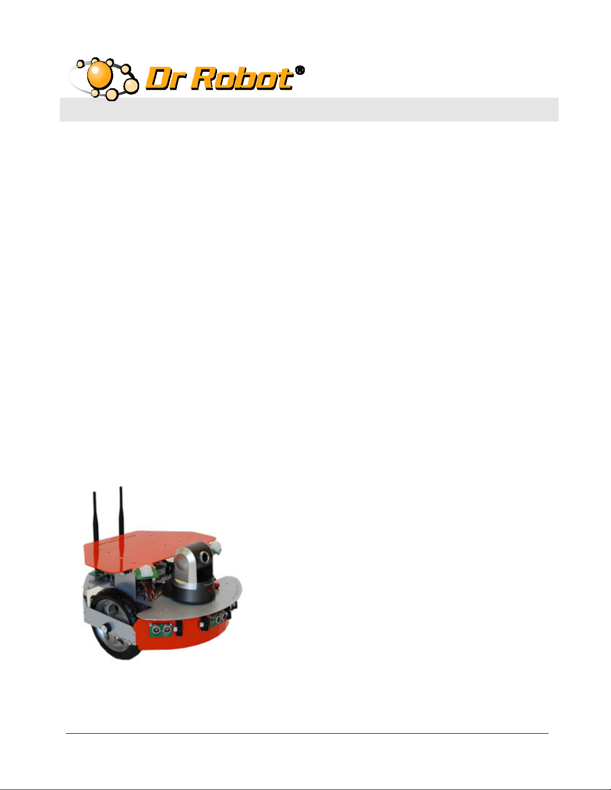
WiFi Mobile Robot Development Platform
with High Resolution Pan-Tilt-Zoom Camera
X80SV
Quick Start Guide
Copyright © 2001 - 2013, Dr Robot Inc. All Rights Reserved.
www.DrRobot.com
Page 2

WARNINGS
Do NOT power on the robot before reading and fully understanding the
operation procedures explained in this manual.
Neither the robot, nor the program is bug free, accidence could happen; you
have to make sure that the robot always maintains a safe distance from
people during operation.
The robot should be turn off (i.e. the power switch should be on OFF
position) when not in used. Battery should be fully charged before
storage. Battery pack should be recharged every two weeks while in
storage.
Failure to follow these warnings could cause serious injury or death and/or
damage to the robot.
Copyright © 2001 - 2013, Dr Robot Inc. All Rights Reserved.
www.DrRobot.com
Page 3

Copyright Statement
This manual or any portion of it may not be copied or duplicated without the expressed written consent of Dr
Robot.
All the software, firmware, hardware and product design accompanying with Dr Robot’s product are solely owned
and copyrighted by Dr Robot. End users are authorized to use for personal research and educational use only.
Duplication, distribution, reverse-engineering, or commercial application of the Dr Robot or licensed software and
hardware without the expressed written consent of Dr Robot is explicitly forbidden.
www.DrRobot.com
Contact
Technical Support: [email protected]
25 Valleywood Drive, Unit 20
Markham, Ontario, L3R 5L9, Canada
Tel: (905) 943-9572 Fax: (905) 943-9197
Copyright © 2001 - 2013, Dr Robot Inc. All Rights Reserved.
www.DrRobot.com
Page 4

Table of Contents
Introduction 5
Key Features 5
Sensors and External Components 6
Operation Scenario 8
Software Installation 9
Robot Operations 10
Recharging 13
Open the Sample Source Code 13
Further Development & Programming 13
Network Connection and Login Information 14
Network Settings 14
Advanced Network Settings 14
Copyright © 2001-2013, Dr Robot Inc. All Rights Reserved.
- 4 -
www.DrRobot.com
Page 5

Introduction
X80SV is designed and built on X80 robot base, featuring high resolution Pan-Tilt-Zoom camera.
Key Features
High resolution Pan-Tilt-Zoom Camera with two-way audio capability
Two 12V motors with over 300oz.-inch (22kg.cm) torque each
Fully wireless networked 802.11g
OS independent application development tools
Max speed of 1 m/sec
128x64 graphic LCD, Display image, message or sensor data
Collision detection sensors include 3 Ultrasonic range sensors and 7 IR range sensors
2 Pyroelectric Human Motion Sensors
Comprehensive circuit protection
Max payload 10 kg (optional 40 kg) with robot weight of 3 kg
Dimension 38cm (L) x 35cm (W) x 28cm (H)
Extended operating time. 3 hours nominal operation time for each recharging
Upgrade options:
o
Supplementary sonar sensors, temperature sensors, acceleration/tilting sensor, or customized
sensors can be added.
o
Vision-landmark base indoor localization (indoor GPS, position/orientation) sensor and the
landmarks together provide precise position and direction information covering every inch of the
floor.
o
Laser scanner.
o
Power and battery systems for 6-hour operation time are available.
Copyright © 2001-2013, Dr Robot Inc. All Rights Reserved.
- 5 -
www.DrRobot.com
Page 6
Sensors and External Components
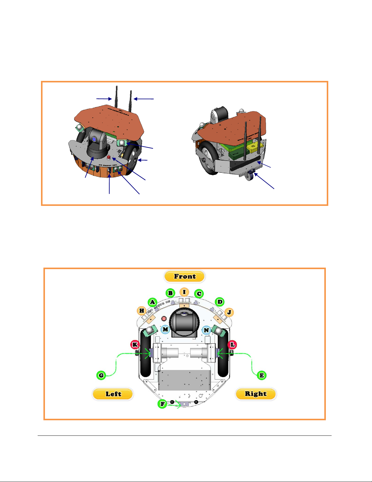
The figure below illustrates the key functional components you will identify on the outside of X80SV robot.
Robot WiFi
Module Antenna
Pan-Tilt-Zoom
Camera
IR Range
Camera Antenna
Human Sensor
Quadrature
Encoder
Main Power Switch
Ultrasonic Sensor
12V Battery Pack
IR Range
X80SV Overview
The robot comes with 3 ultrasonic range sensors and 7 IR range sensors. These range sensors are for
environment detection and collision avoidance.
X80SV Sensor Module Location (Top View)
Copyright © 2001-2013, Dr Robot Inc. All Rights Reserved.
- 6 -
www.DrRobot.com
Page 7
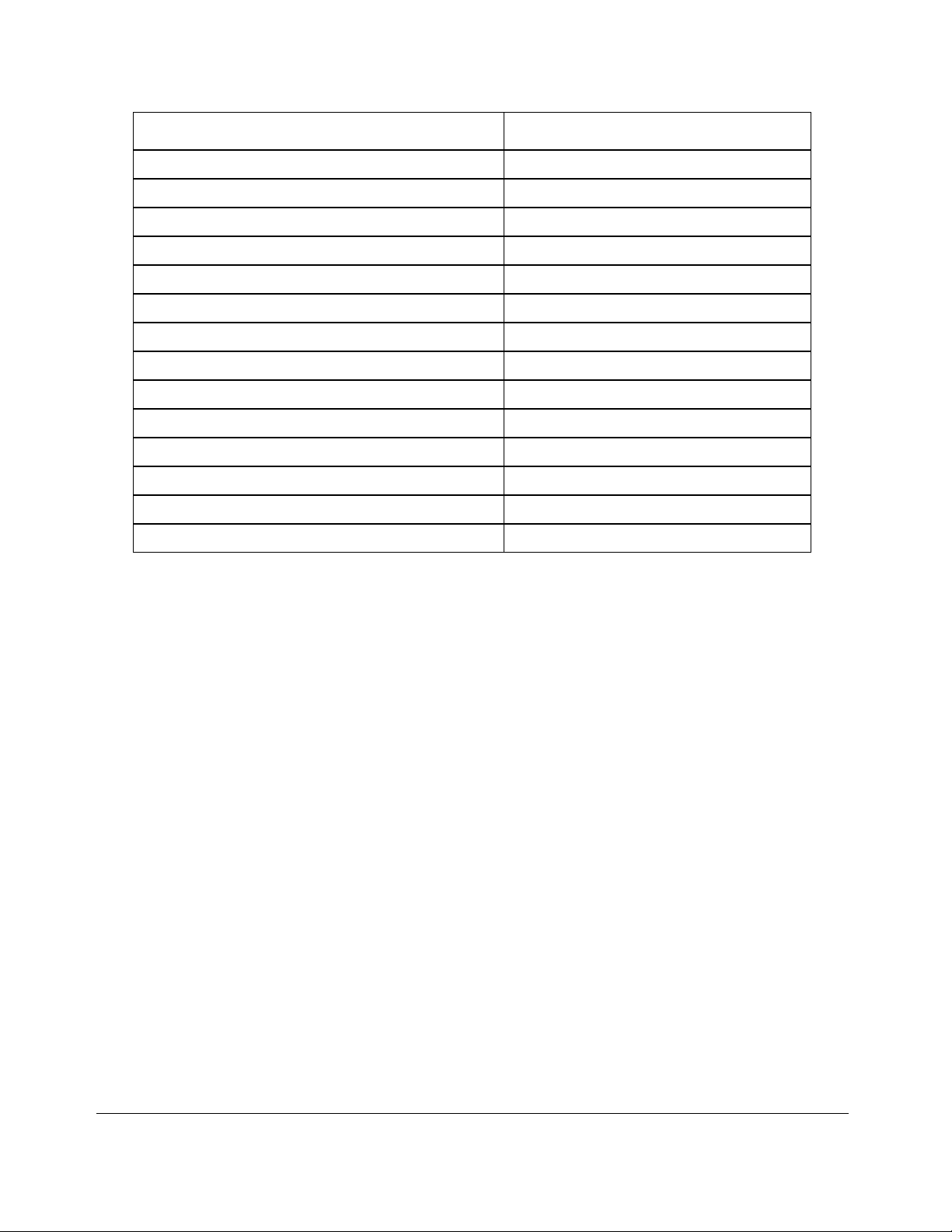
Sensor Module Location
Ultrasonic #1 H – Left front
Ultrasonic #2 I – Middle front
Ultrasonic #3 J – Right front
Human Sensor #1 M – Left front
Human Sensor #2 N – Right front
Infrared Range Sensor #1 A – Front left
Infrared Range Sensor #2 B – Front middle
Infrared Range Sensor #3 C – Front middle
Infrared Range Sensor #4 D – Front right
Infrared Range Sensor #5 E – Right
Infrared Range Sensor #6 F – Rear
Infrared Range Sensor #7 G – Left
Quadrature Encoder #1 K - Left , use channel 1
Quadrature Encoder #2 L - Right, use channel 2
Copyright © 2001-2013, Dr Robot Inc. All Rights Reserved.
- 7 -
www.DrRobot.com
Page 8
Operation Scenario
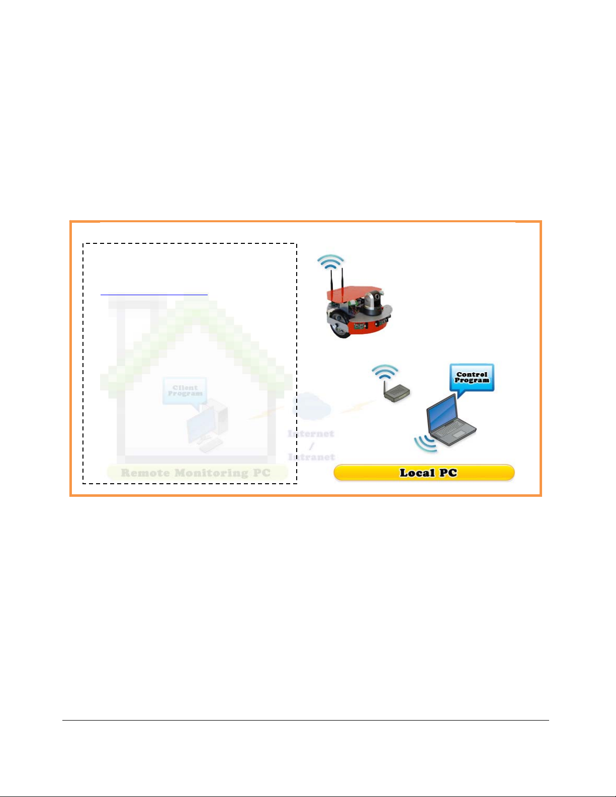
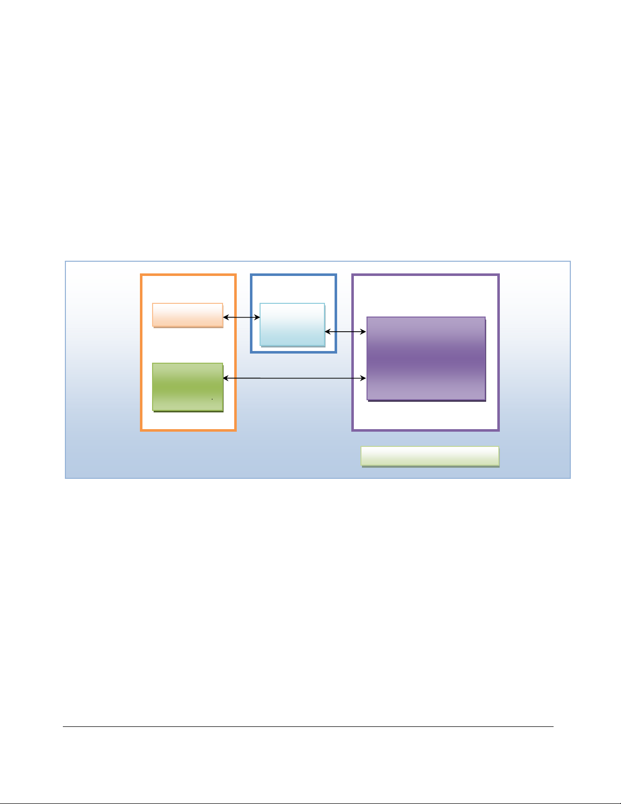
Diagram below shows the typical operation scenario. The X80SV is a wireless networked robot. It connects to
the wireless AP or router via IEEE 802.11b/g network. The Local PC running the X80SV Control program could
connect to this network via either:
Network cable – Connect the host PC to one of the LAN ports on the back of the router (DO NOT
connect to the WAN port), or
Wireless – To connect the Local PC to the wireless router, configure the Local PC’s wireless settings
using the default wireless configuration settings found in the Network Connection session of this manual.
User could write his own remote
control program or contact
[email protected] for further
support.
Typical Operation Scenario
Note: The Local PC could also be mounted on the robot instead off the robot if your application requires so.
User could be able to control the robot, see, talk and listen through the robot via the Dr Robot
Copyright © 2001-2013, Dr Robot Inc. All Rights Reserved.
- 8 -
www.DrRobot.com
® Control program.
Page 9
Software Installation
You should install the “X80SVControl” program from the installation CD.
After program installation, you will find the following programs under the “Start-All Programs” list, and they are
installed under the “Program Files” folder.
Dr Robot Inc – X80SV Control
Dr Robot Inc – WiRobotGateway.exe
“SourceCode” folder contains a copy of X80SV sample code for Visual Studio 2008. It is locate under default
installation folder (such as “C:\Program Files\Dr Robot Inc\Dr Robot X80SV Control Program\”)
* DirectX
® SDK is required. You could download it from Internet
* Microsoft
Robot
Motion/Sensor
System
Pan-Tilt-Zoom
Camera
(192.168.0.199:
8081 *)
WiFi
Motion Control
Gateway
(Port 10001*)
* Default Setting
® .Net 3.5 Framework is required. You could download it from
Local PC
X80SV
Control Program
Copyright © 2001-2013, Dr Robot Inc. All Rights Reserved.
- 9 -
www.DrRobot.com
Page 10
Robot Operations
Step 1: If you have not installed the demo and support programs, insert the
installation CD to CDROM and run the “Setup.exe” program that is under “X80SV
Control Installation” folder.
Step 2: Connect the PC to the wireless router (one of the LAN ports) (the router
has IP 192.168.0.200) included in the package.
Step 3: Push red power switch on the front to turn on the robot.
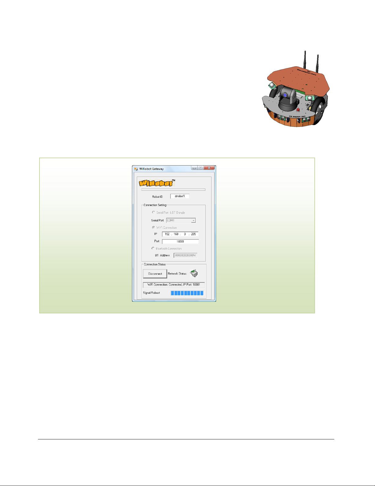
Step 4: Run the “WiRobotGatewayforWiFi.exe” from Start -> All Programs -> Dr
Robot Inc -> WiRobotGateway.exe, Use “drrobot1” as robot ID, enter your robot IP address to “IP” textbox,
“10001”as “Port”, and then click “Connect”.
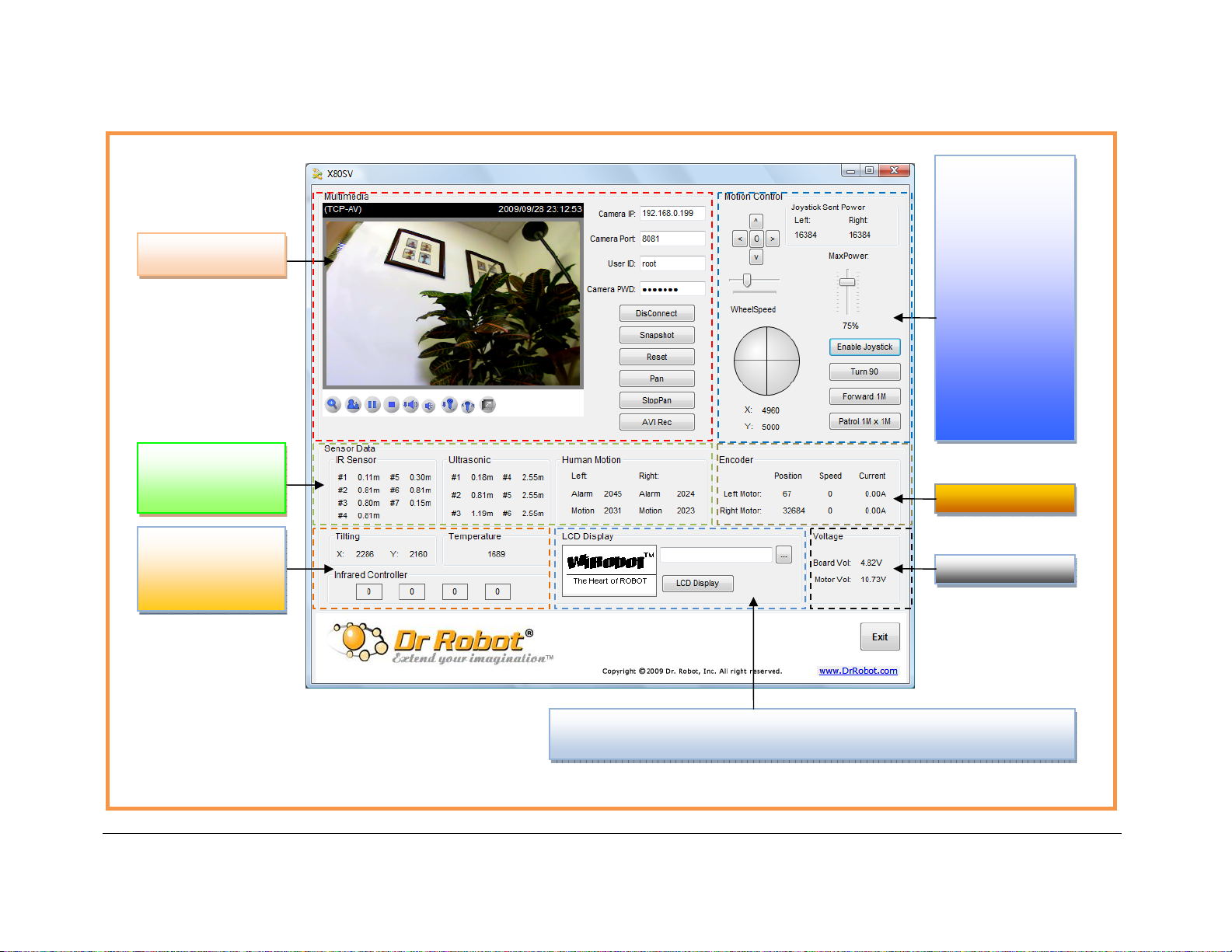
Step 5: Run the “X80SV.exe” from Start -> All Programs -> Dr Robot Inc -> X80SV Control. Once the GUI popup,
enter the camera login information, and then click “Connect”.
Copyright © 2001-2013, Dr Robot Inc. All Rights Reserved.
- 10 -
www.DrRobot.com
Page 11
g
Camera display and
IR, Ultrasonic,
Human sensors
reading
Motion control
* Joystick Control
(Optional)
* Click “Turn 90”
to command robot
to turn 90º
* Click “Forward
1M” to command
robot to go
forward by 1 meter
* Click “Patrol 1M x
1M” to command
robot to patrol on 1
meter by 1 meter
Encoder reading
Tilting, Temperature
sensor reading and
Infrared Controller
reading (Optional)
Copyright © 2001-2013, Dr Robot Inc. All Rights Reserved.
Voltage readin
* Select 128x64 monochrome Bitmap file to display on LCD (Optional)
* Click “LCD Display” to display the battery voltage reading on LCD (Optional)
- 11 -
www.DrRobot.com
Page 12
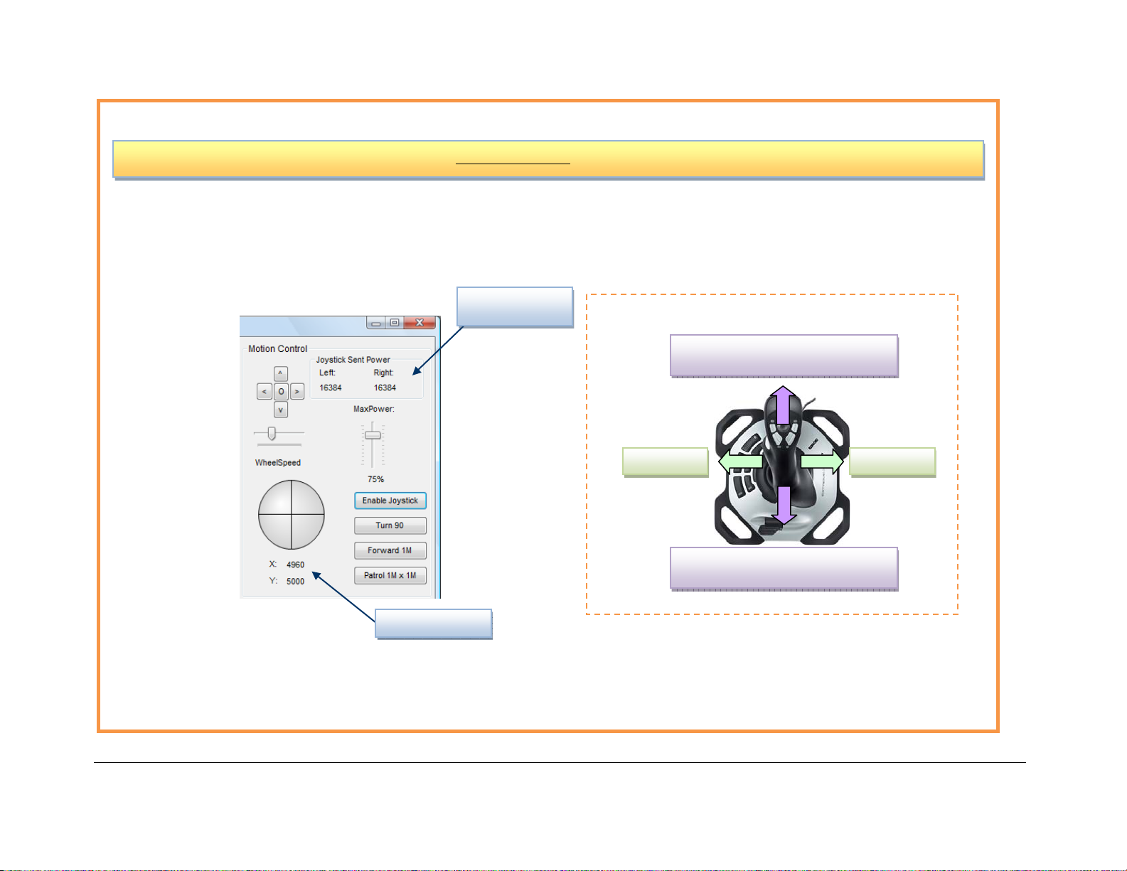
Joystick Control (Optional)
y
y
The value for
Driving with Joystick
Go Forward
ou push, faster the robot goes
More
Turn RightTurn Left
Go Backward
ou push, faster the robotgoes
More
Joystick reading
Copyright © 2001-2013, Dr Robot Inc. All Rights Reserved.
- 12 -
www.DrRobot.com
Page 13

Recharging
To keep the battery at ideal condition, we recommend recharging the robot at least once every two weeks during
storage (e.g. robot is not in use).
Open the Sample Source Code
Open “C:\Program Files\Dr Robot Inc\Dr Robot X80SV Control Program\SourceCode” folder, run
“X80SV.csproj” to open project in Microsoft
® Visual Studio 2008.
Further Development & Programming
The X80SV Control program is written with C# program with Visual Studio 2008 express under .Net 3.5
framework. You could download the development tools (Visual Studio 2008 express under .Net 3.5 framework)
free from Microsoft. Please refer to the “Dr Robot Application Development Notes on C# Programming for Robot
Control” for further information.
The control program uses the supporting components and libraries that should have been installed when you
install the control programs from the installation CD:
1. DRROBOTSentinelCONTROL.OCX: Please refer to “WiRobot SDK API Reference Manual.pdf” for
detail.
2. WiRobotGatewayforWiFi.exe
3. VitaminCtrl.dll
4. DirectX® SDK
5. Microsoft® .Net 3.5 Framework
For support on development using Microsoft Robotics Studio, development on operation system other than MS
Windows, or obtaining raw communication protocol, please contact [email protected].
Copyright © 2001-2013, Dr Robot Inc. All Rights Reserved.
- 13 -
www.DrRobot.com
Page 14
Network Connection and Login Information
Network Settings
The included pre-configured wireless 802.11 b/g router has the following pre-set settings:
SSID dri Router LAN 192.168.0.200
WEP 128bits Login ID admin
KEY 112233445566778899AABBCCDD Password drrobot
Key Type Open Key
WiFi module connects to two serial devices through channel I and II (TCP/IP port 10001 and 10002
respectively). They are pre-configured as below:
Name Robot WiFi Module IP
Channel-I
(10001)
115200, 8,N,1, flow control, UDP, Datagram
01, remote IP:0.0.0.0
Channel-II
(10002)
192.168.0.205
115200, 8,N,1, flow control, UDP, Datagram
01, remote IP:0.0.0.0
Advanced Network Settings
It’s possible to use different network settings (e.g. IP) for the server PC, but the “Virtual Server” settings on the
router must also be changed accordingly in order for the Internet remote monitoring feature to work properly.
You could also change the router settings such as IP and SSID etc. If you need to do so, you are required to
change the network settings on the WiFi modules on the robot by following the guidelines as illustrated on the
WiFi Module manual.
Support Team Contact Information:
Copyright © 2001-2013, Dr Robot Inc. All Rights Reserved.
- 14 -
www.DrRobot.com
 Loading...