

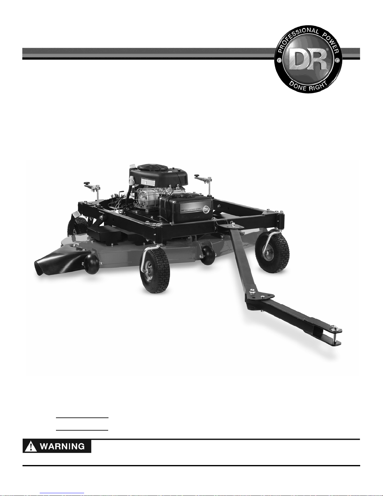
TOW-BEHIND DR
SAFETY & OPERATING INSTRUCTIONS
Models: Mow Pro-44
Mow Pro-60
®
FIELD and FINISH MOWER
Serial No.
Order No.
Read and understand this manual and all instructions before operating the TOW BEHIND DR FINISH MOWER.
DR Power Equipment
Toll-free phone: 1-800-DR-OWNER (376-9637)
Fax: 1-802-877-1213
Website: www.DRpower.com

2 TOW BEHIND DR
®
FIELD and FINISH MOWER
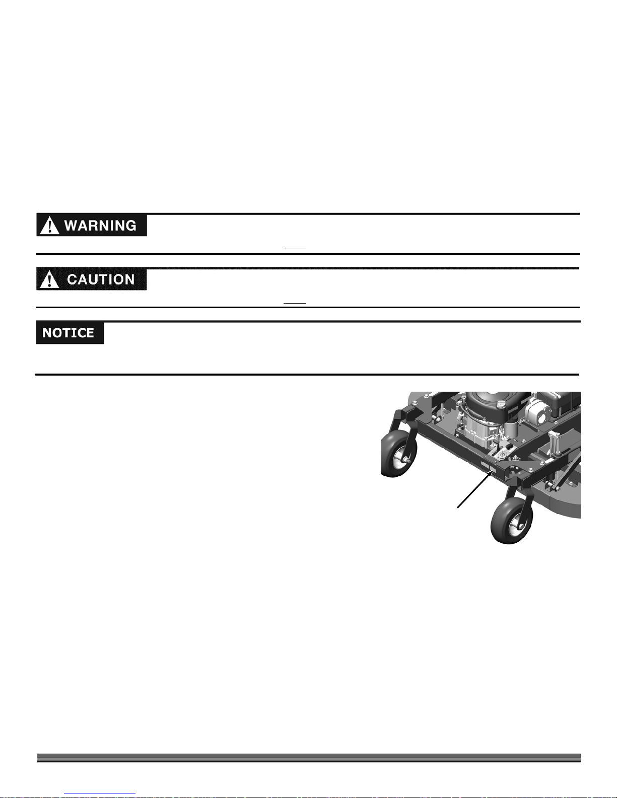
Table of Contents
Chapter 1: General Safety Rules ............................................................................................................................................................ 5
Chapter 2: Setting up The TOW-BEHIND DR FIELD and FINISH MOWER ...................................................................................... 8
Chapter 3: Operating the TOW-BEHIND DR FIELD and FINISH MOWER ........................................................................................ 16
Chapter 4: Maintaining the TOW-BEHIND DR FIELD and FINISH MOWER .................................................................................... 21
Chapter 5: Troubleshooting .................................................................................................................................................................. 28
Chapter 6: Parts Lists and Schematic Diagrams .................................................................................................................................. 30
Conventions used in this manual
This indicates a hazardous situation, which, if not avoided, could result in death or serious injury.
This indicates a hazardous situation, which, if not avoided, could result in minor or moderate injury.
This information is important in the proper use of your machine. Failure to follow this instruction could result in damage to your
machine or property.
Serial Number and Order Number
A Serial Number is used to identify your machine and is located on the Serial
Number Label on your machine (Figure 1). An Order Number is used to check
and maintain your order history and is located on the upper left portion of your
packing slip. For your convenience and ready reference, enter the Serial
Number and Order Number in the space provided on the front cover of this
manual.
Additional Information and Potential Changes
DR Power Equipment reserves the right to discontinue, change, and improve its
products at any time without notice or obligation to the purchaser. The
descriptions and specifications contained in this manual were in effect at
printing. Equipment described within this manual may be optional. Some
illustrations may not be applicable to your machine.
Serial Number Label
Figure 1
CONTACT US AT www.DRpower.com 3

4 TOW BEHIND DR
®
FIELD and FINISH MOWER
Chapter 1: General Safety Rules
#
#
#
#
#
#
#
#
#
#
Read this Safety & Operating Instructions manual before you use the TOW BEHIND DR FINISH MOWER. Become familiar with
the operation and service recommendations to ensure the best performance from your machine. If you have any questions or
need assistance, please contact us at www.DRpower.com or call toll-free 1-800-DR-OWNER (376-9637) and one of our Technical
Support Representatives will be happy to help you.
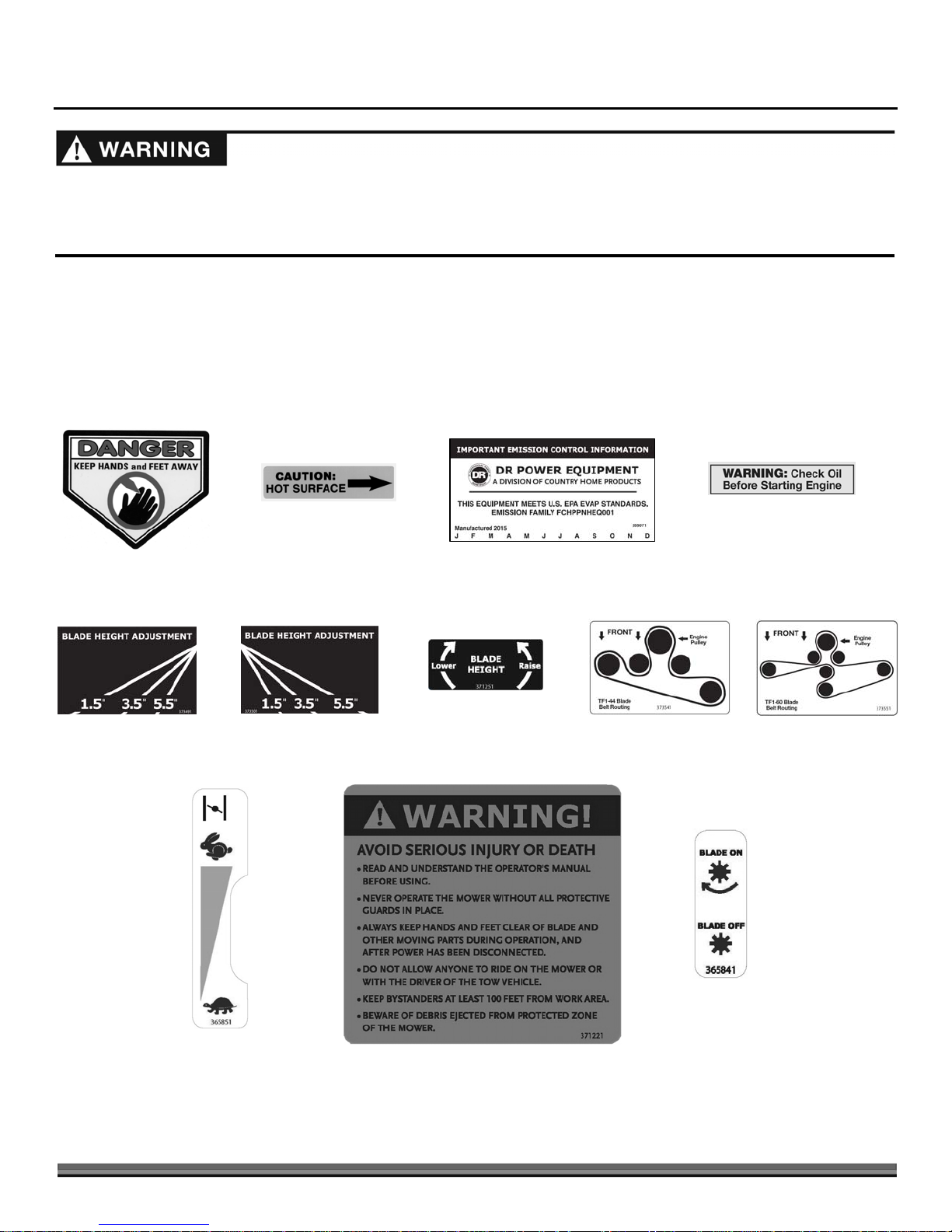
Labels
Your TOW-BEHIND DR FIELD and FINISH MOWER carries prominent labels as reminders for its proper and safe use. Shown
below are copies of all the Safety and Information labels that appear on the equipment. Take a moment to study them and make a
note of their location on your Mower as you set up and before you operate the unit. Replace damaged or missing safety and
information labels immediately.
13683
13649
37349
37350
37125
#35507
37354
37355
36584
36585
37122
CONTACT US AT www.DRpower.com 5

Protecting Yourself and Those around You
This is a high-powered machine with moving parts operating at high speeds. Always take the following precautions when
operating this machine:
Always wear protective goggles or safety glasses with side shields.
We recommend wearing sturdy shoes with non-slip tread, long pants, and gloves while using this machine. Be sure the
gloves fit properly and do not have loose cuffs or drawstrings.
Use ear protectors or ear plugs.
Allow only responsible adults who are familiar with these safety rules and operating instructions to use your DR FINISH
MOWER.
Keep your hands and feet away from the blades, belt, pulley, and concealed areas while the engine is running.
Keep people and pets away from your machine and out of the work area at all times. Disengage the blade and stop the engine
if a person or pet is within 100 feet of the machine.
Children are often attracted to the machine and the mowing activity. Never assume that children will remain where you last
saw them.
Never allow people to ride on the mower.
Before mowing, clear the area of objects such as rocks, toys, wire, bones, sticks, etc.
Never remove or alter standard parts or add anything to the DR FINISH MOWER, especially all shields and guards.
Before and while moving backwards, look behind, and down for small children.
Use extra care when approaching blind corners, shrubs, trees, or other objects that may obscure your vision.
Safety with Gasoline - Powered Machines
Gasoline is a highly flammable liquid that gives off flammable vapor that can be ignited and cause a fire or explosion. Always
follow these precautions:
Never run the engine in an enclosed area or without proper ventilation as the exhaust contains carbon monoxide, an odorless,
tasteless, and poisonous gas.
Store all fuel and oil in containers specifically designed and approved for this purpose. Keep away from heat and open flame
and out of the reach of children.
Replace rubber fuel lines and grommets when worn or damaged or after 5 years of use, whichever comes first.
Fill the gasoline tank outdoors with the engine off and after the engine has cooled completely. Don't handle gasoline if you or
anyone nearby is smoking.
If you spill gasoline do not start the engine. Move the machine away from the area until the gas vapors have dissipated.
Before performing engine maintenance or repairs, shut down the engine, disconnect the spark plug wire, and wait 5 minutes
for the engine to cool.
Never change the engine governor settings or modify the engine speed.
Never check for an ignition spark with the spark plug or spark plug wire(s) removed. Always use an approved spark tester.
Never tamper with safety devices. Regularly check their proper operation.
Allow the engine to cool completely before storing in any enclosed area.
Keep combustible substances away from the engine when it is hot. Never cover the machine while the muffler is still hot.
To reduce fire hazard, keep the engine and muffler free of debris build-up.
Do not operate the engine with the air cleaner or the carburetor air intake cover removed.
Do not use flammable solutions to clean the air filter.
Never operate the engine without the muffler and deflector, if so equipped. Inspect the muffler and deflector periodically and
replace if necessary.
The muffler and engine become very hot and can cause a severe burn. Do not touch.
6 TOW BEHIND DR
®
FIELD and FINISH MOWER

Slope Operation
Use of machinery on slopes is a major factor in outdoor power equipment accidents. All slopes require caution. If you feel uneasy
on a slope, do not mow it. Always take the following precautions when using this machine on slopes:
Operate the machine up and down the face of slopes. Exercise extreme caution when changing direction on slopes.
Never operate near drop-offs, ditches, or embankments or on slopes greater than 20 degrees.
Never operate on wet or slippery slopes.
Never park the tow vehicle on a steep grade or slope.
General Safety
Safe operation of the TOW-BEHIND DR FINISH MOWER is necessary to prevent death or serious injury. Always take the
following precautions when operating this machine:
The TOW-BEHIND DR FINISH MOWER is designed to mow grass. Do not use it for any other purpose.
If the machine makes an unusual noise or vibration or if there are obstructions underneath the machine, shut off the tow
vehicle and the DR FINISH MOWER engines. Wait five minutes for the engine to cool. Disconnect the spark plug wire and
then inspect the machine for clogs or loose parts. Clear any obstructions and repair and/or replace damaged parts.
The mower blades are sharp. Wrap the blades or wear gloves and use extra caution when servicing.
Always keep the machine in good, safe operating condition. Always make certain nuts and bolts are tight. Do not use
substitute hardware.
Use the TOW-BEHIND DR FINISH MOWER only in daylight.
Always give undivided attention to the machine and your surroundings. Watch for traffic when mowing near roadways.
Disengage the mower blades and exercise extreme caution when on or crossing drives, walks, or roads.
If leaving the machine, shift the tow vehicle into neutral and set the parking brake; turn off the tow vehicle engine and remove
its key. Turn off the DR FINISH MOWER engine and remove its key.
Do not operate the mower when under the influence of alcohol, drugs, or medication.
Do not operate the mower when there is a risk for lightening.
California Proposition 65
California Proposition 65:
Engine exhaust and some of its constituents are known to the State of California to cause cancer, birth defects, and other
reproductive harm.
This product contains or emits chemicals known to the State of California to cause cancer, birth defects, and other
reproductive harm.
A Note to All Users
Under California law, and the laws of some other states, you are not permitted to operate an internal combustion engine using hydrocarbon
fuels without an engine spark arrester. This also applies to operation on US Forest Lands. All TOW-BEHIND DR FIELD and FINISH MOWERS
shipped to California, New Mexico and Washington State are provided with spark arresters. Failure of the owner or operator to maintain this
equipment in compliance with state regulations is a misdemeanor under California law and may be in violation of other state and/or federal
regulations. Contact your State Park Association or the appropriate state organization for specific information in your area.
No list of warnings and cautions can be all-inclusive. If situations occur that are not covered by this manual, the operator must apply common
sense and operate this TOW-BEHIND DR FIELD and FINISH MOWER in a safe manner. Contact us at www.DRpower.com or call 1-800-DROWNER (376-9637) for assistance.
CONTACT US AT www.DRpower.com 7

Chapter 2: Setting up The TOW-BEHIND DR FIELD and FINISH MOWER
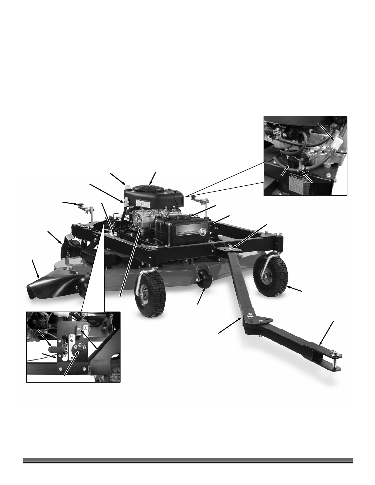
It may be helpful to familiarize yourself with the controls and features of your TOW-BEHIND DR FIELD and FINISH MOWER by
reviewing Figure 2 before beginning these procedures. If you have any questions at all, please feel free to contact us at
www.DRpower.com.
TOW-BEHIND DR FIELD and FINISH MOWER Controls and Features (Mow Pro-44 Model)
Note: The model shown in Figure 1 may look slightly different from your machine.
Fuel Filter
Pull Start
Fuel Fill
Oil Fill
Cap/Dipstick
Handle
DR 13.3 TQ
Engine
Fuel Filter
Hand Crank
Height Adjusters
Rear Fixed
Wheels
Discharge
Guard
Throttle
Control
Control
Panel
Oil Drain Tube
Muffler
Tow Bar
Carbon
Canister
Left Side
Tow Bar Locking Pin
Front Caster
Wheels
Tow Hitch
Blade
Engage
Switch
Key Switch
8 TOW BEHIND DR
®
FIELD and FINISH MOWER
Figure 2
A
r
TOW-BEHIND DR FIELD and FINISH MOWER Controls and Features (Mow Pro-60 Model)
Note: The model shown in Figure 1 may look slightly different from your machine.
Fuel Filter
Oil Drain Hose
Hand Crank
Height Adjusters
Rear Fixed
Wheels
Discharge
Guard
Throttle
Control
Oil Fill
Cap/Dipstick
Battery
Muffler
Briggs and
Stratton 14.5 HP
Engine
Wheels
nti-Scalping
Fuel Fill
Fuel Tank
Fuel Filter
Fuel Shutoff
Valve
Front Caster
Wheels
Oil
Filte
Left Side14.5 HP Engine
Tow Bar Locking Pin
Tow Hitch
Control
Panel
Key Switch
Blade
Engage
Switch
Tow Bar
Figure 3
CONTACT US AT www.DRpower.com 9

Specifications
g
Engine See your Engine Manual for oil capacity and other
Starting System Manual Start Electric Start
Fuel Tank 3.5 L (.92 gal), Gasoline, Unleaded 2.5 Gal. (9.46 L), Gasoline, Unleaded
Battery NA 12V, 9Ah
Wheels Front: 11 X 4 Turf Tread
Distance From
Centerline of Tow
Vehicle to Outer
Cutting Edge
Number of Offset
Positions
Adjustable Cutting
Height
Cutting Width 44" 60"
Cutting Capacity 2' high grass 2' high grass
Blade Tip Speed 18,500 - 19,000 ft/min 17,500 - 18,000 ft/min
No. of Blades 2 3
Blades Type Air Tipped Air Tipped
Deck 12 GA Welded Steel 12 GA Welded Steel
Discharge Side Side
Spindle 1" Dia. Shaft with 2 Sealed 20 mm Bearings 1" Dia. Shaft with 2 Sealed 20 mm Bearings
Belt A76 AK124
Electric Clutch 75 ft-lb 75 ft-lb
Max Speed Mow/Tow 5mph 5mph
Tongue Weight 10 lbs. 10 lbs.
Machine Dimensions 132" L x 60" W x 29" T 132" L x 75" W x 26" T
Machine Weight 270 lbs. 320 lbs.
13.3 TQ Mow Pro-44 Model 14.5 HP Mow Pro-60 Model
See your Engine Manual for oil capacity and other
ine specifications.
En
Rear: 11 X 4 Turf Tread
Straight Back: 22"
Offset Position 1 (either L or R): 49.5"
Offset Position 2 (either L or R): 68"
5 5
From 1-1/2"min. to 5-1/2" max. From 1-1/2"min. to 5-1/2" max.
Engine specifications.
Front: 11 X 4 Turf Tread
Rear: 11 X 4 Turf Tread
Straight Back: 30"
Offset Position 1 (either L or R): 57.5
Offset Position 2 (either L or R): 76"
1
2
6
Figure 4
10 TOW BEHIND DR
®
FIELD and FINISH MOWER
3
5
Assembling the TOW-BEHIND DR FIELD and FINISH MOWER
Hardware Supplied in Product Package (Figure 4 and Table below):
4
Item #
Part # Description Qty
1 ............. 23499 .......... Washer, SAE Flat, 1/2", ZP ...............................................4
2 ............. 35281 .......... Bolt, Hex, Flange, Tri Lobe, 3/8-16 X 3/4", GR5 ZP ........5
3 ............. 25549 .......... Pin, Clevis, 1/2" x 2 1/2", TRT ..........................................3
4 ............. 18737 .......... Pin, Clevis, 1/2" OD X 4.5" LG .........................................1
5 ............. 16003 .......... Pin, Hair, 1/2" To 9/16", .12" Wire ..................................4
6 ............. 15720 .......... Key Ignition Switch ...........................................................2
Compare the hardware of the Product Package with Figure 4 and the “Hardware
Supplied” list above. If you have any questions, please contact us at
www.DRpower.com.
The Mow Pro-44 Model is shipped mostly assembled. Go to “Installing the
A
A
A
k
Discharge Guard” section if you have a Mow Pro-44 Model.
Tools and Supplies Needed:
Wire Cutters
Two 3/4" Wrenches
7/8" Socket with Torque Wrench
1-1/16" Wrench*
5/16" Wrench
Blocking
*or Adjustable Wrench
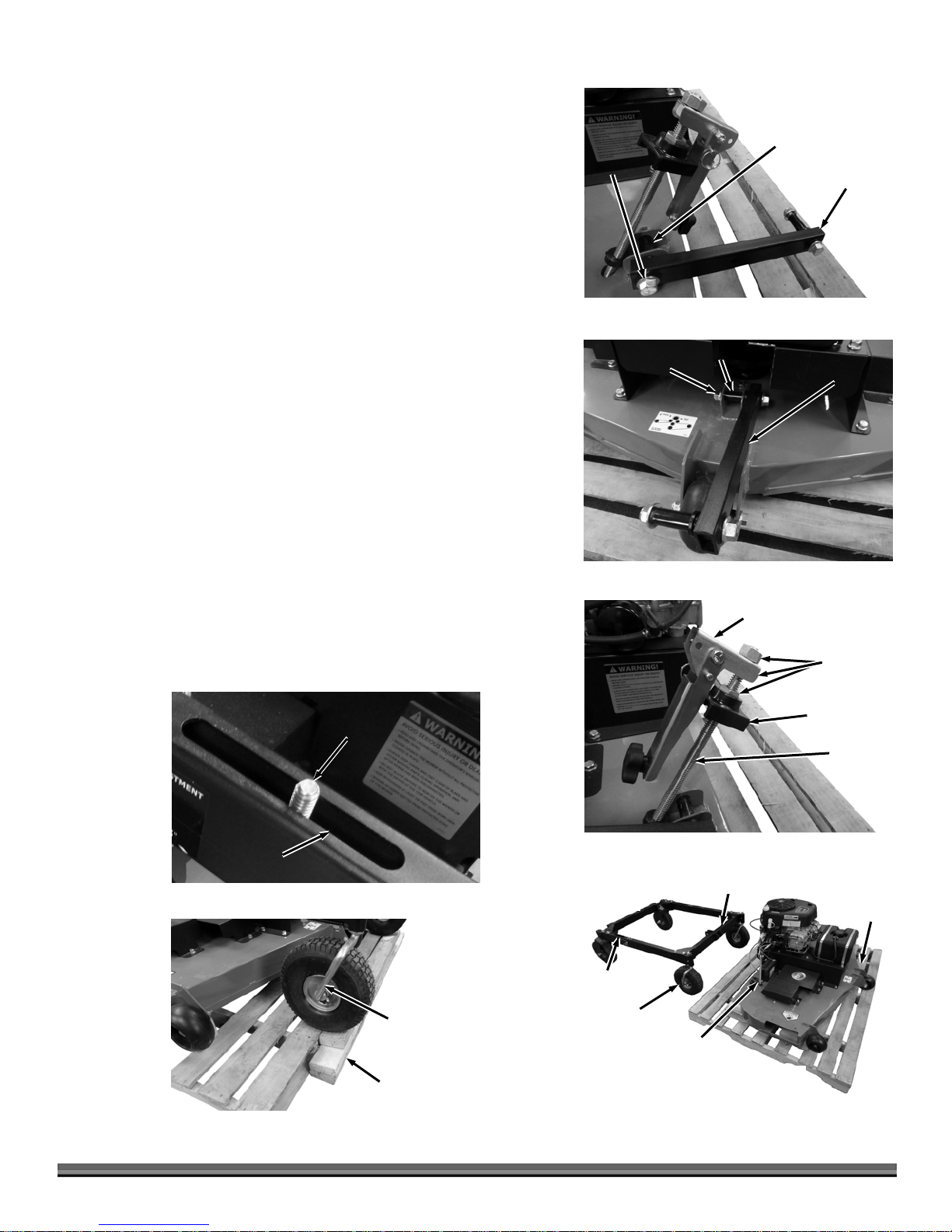
Assembling the Deck to the Frame (Mow Pro-60 Model only)
Bolt and
Locknut
Figure 5
Bushing
Sway Brace
1. Leave the Deck Bushings in place as you remove the Bolt and Locknut (by
hand) that secures the two side Sway Braces to the Deck (Figure 5).
2. Leave the Deck Bushing in place as you remove the Bolt and Locknut (by
hand) that secures the front Sway Brace to the Deck (Figure 6).
3. Remove the remaining Bolts and Locknuts from the three Sway Braces.
4. Remove the three Nuts, Hand Crank and Height Adjust Block from both
threaded Rods (Figure 7).
5. Position the two Threaded Rods so they are vertical.
6. Place the Frame Assembly as shown with the Caster Wheels next to the back
of the Deck Assembly. Turn the Casters toward the rear wheels (Figure 8).
7. With the help of another person, position the Frame over the Deck
Assembly with the Threaded Rods through the slots in the Frame (Figure 9).
Note: We recommend adding Blocking at both sides of the Pallet to help stabilize
the Wheels (Figure 10).
Threaded
Rod
Bolt and
Locknut
Figure 6
Bushing
Sway Brace
Hand Crank
Nuts
Height
djust Bloc
Threaded
Rod
Slot in
Frame
Figure 9
Figure 10
Caster Turned
towards Rear
Blocking
Figure 7
Frame
ssembly
Slot
Caster
Turned
this way
Figure 8
CONTACT US AT www.DRpower.com 11
Front
Threaded
Rod
Front
Deck
ssembly
Bolt and Locknut
Figure 11
Bolt and
Locknut
Figure 12
Bushing
Bushing
Bushing
Shoulder
Bushing
Threaded Rod
Bushing
Shoulder
Sway Brace
Height Adjust
Block
Bushing
Shoulder
Sway
Brace
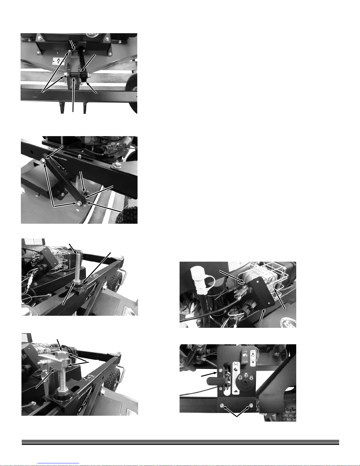
Note: The Bushings in the Deck Brackets should still be in place as instructed in
earlier steps.
8. Install the Bushing into the Bracket at the front of the Frame with the long
portion of the Bushing fully into the Frame Bracket (Figure 11). The Bushing
shoulder should be tight against the Bracket.
9. Install and secure the front Sway Brace with the two Bolts and Locknuts
using two 3/4" Wrenches.
10. Install the Bushings into the sides of the Frame with the long portion of the
Bushing fully into the Frame Bracket (Figure 12). The Bushing shoulder
should be tight against the Bracket.
11. Install and secure the two side Sway Braces with the Bolts and Locknuts
using two 3/4" Wrenches.
12. Pull up on the Threaded Rod and install the Height Adjust Block as far as it
will go followed by a Nut (Figure 13). When the Nut touches the Block, turn
the Rod so the Nut can set inside the Block.
13. Install a Nut at the top of the Threaded Rod, followed by the Hand Crank
and then another Nut (Figure 14).
Note: When tightened in the next step, the top nut must be flush with the end of the
Threaded Rod.
14. Hold the Hand Crank with a 1-1/16" Wrench (or Adjustable Wrench) as you
tighten the top Nut against the Hand Crank using a 7/8" Socket and Torque
Wrench to 25-30 ft-lbs.
15. Cut the Cable Tie that is securing the Control Panel to the Muffler Guard
using Wire Cutters (Figure 15).
16. Remove the Screws from the Frame using a 5/16" Wrench and install
Control panel to the Frame (Figure 16).
Nut
Figure 13
Top of Threaded Rod
Hand
Crank
Figure 14
12 TOW BEHIND DR
Nut
®
FIELD and FINISH MOWER
Cable Tie
Muffler
Control Panel
Figure 15
Control
Panel
Frame
Screws
Figure 16
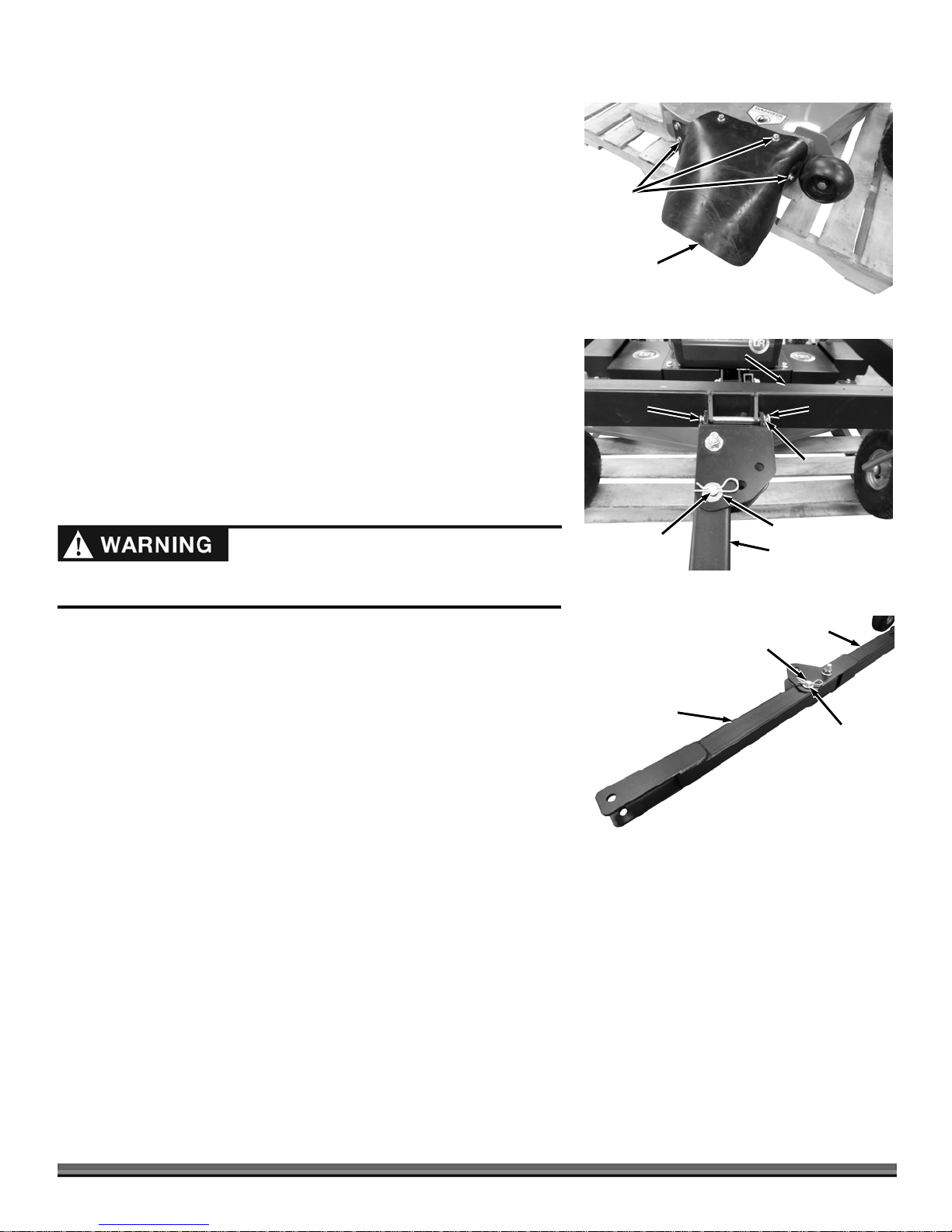
Installing the Discharge Guard
1. Install the Discharge Guard with five 3/8-16 X .75" Bolts using a 9/16"
Wrench (Figure 17).
Note: If it is difficult to install the Bolt at the front (Mow Pro-60 Model) the Anti-
scalping Wheel can removed using a 9/16" Wrench and Adjustable Wrench
to make it easier.
Bolts
Attaching the Tow Bar to the Push Bar
The Tow Bar can be installed for offsetting to the right or left depending on
which side of the Tow Vehicle you choose to mow. See section “Offset
Mowing” in Chapter 3 to determine how the Tow Bar should be installed for
your needs. The following steps describe positioning the Offset Bracket to
allow offset to the right side of the Tow Vehicle.
1. Secure the Offset Bracket to the Push Bar in the configuration shown (for
right side offset) using the 4.5" long Clevis Pin, Washer, and Hair Pin
(Figure 18).
2. Align the Tow Bar so it is pointed straight out from the Mower and install a
Clevis Pin, Washer, and Hair Pin in the Offset Bracket to lock the Tow Bar in
position.
Always install the Clevis Pins from the bottom with the Washers and Hair Pins
on top to prevent the Hair Pin from being pulled out by tall grass or bushes.
3. Align the Tow Bar Extension with the Tow Bar and install a Clevis Pin,
Washer, and Hair Pin in the Tow Bar to lock the Tow Bar Extension in place
(Figure 19).
4. Raise the Deck (see “Adjusting the Mower Deck Height” in Chapter 3) and
with a helper, roll machine backwards off Pallet. You May need to use a bar
to lift deck over the Blocks if it gets hung up.
Discharge
Guard
Figure 17
Clevis
Pin
Clevis Pin
and Hair Pin
Figure 18
Tow Bar
Extension
Push Bar
Offset
Bracket
Clevis Pin
and Hair Pin
Hair Pin
Washer
Washer
Tow Bar
Tow Bar
Washer
Figure 19
CONTACT US AT www.DRpower.com 13

g
Oil Fill
Fuel Fill
Adding Oil and Gasoline
Tip: To avoid confusion, we recommend leaving the caps on the Fuel and Oil
Fills until you are ready to pour either gasoline or oil into the correct Fill.
ine Oil and Fuel Capacities
En
DR – 13.3 TQ 37 oz (1.1 L) 0.92 gal (3.5 L)
Briggs and Stratton – 14.5 HP 48 oz. w/Filter 2.5 Gal (9.46 L)
Oil (SAE 30 HD) Fuel (Unleaded)
Figure 20a: DR 13.3 TQ Engine
Oil Fill
Figure 20b: Briggs and Stratton 14.5 HP Engine
Oil Lower
Limit
Oil Upper
Limit
Figure 21
Fuel Fill
Oil Dipstick
Green
Negative
(ground)
Wire
Note: Use only SAE 30 HD (High Detergent) oil. Other types of oil could cause
problems with the operation of your machine.
Please refer to your Engine Owner’s Manual for detailed information for Oil and Fuel
procedures.
You must add oil before starting the engine. This machine is shipped
without oil. Traces of oil may be in the reservoir from factory testing, but
YOU MUST ADD OIL BEFORE STARTING THE ENGINE
. Fill the
reservoir slowly, checking the level frequently to avoid overfilling.
To get an accurate reading when checking the oil level:
- The machine should be on a level surface.
- 13.3 TQ Engine: The dipstick SHOULD NOT
- 14.5 HP Engine: The dipstick SHOULD
1. Place the machine on a level surface and remove the Oil Fill Cap/Dipstick
(Figure 20a: Mow Pro-44) (20b: Mow Pro-60).
2. Initially add 32 oz. of SAE 30 High Detergent oil (recommended by the
Engine Manufacturer) into the Oil Fill and wait one minute for the oil to
settle.
3. 13.3 TQ Engine
: Replace the Dipstick but DO NOT screw on, and then
remove it to check the oil level (Figure 21). Continue adding a few ounces of
oil at a time, rechecking the Dipstick until the oil reaches the fill mark. Be
careful not to overfill.
14.5 HP Engine
: Replace the Dipstick and screw on fully, and then remove it to
check the oil level (Figure 21). Continue adding a few ounces of oil at a time,
rechecking the Dipstick until the oil reaches the fill mark. Be careful not to
overfill.
4. Remove the Fuel Cap and fill the gas tank to within 1-1/2" below top of fill
neck (to allow for fuel expansion) with fresh, unleaded gas (Figure 20a: Mow
Pro-44) (20b: Mow Pro-60). Replace the Fuel Cap when finished.
be screwed down.
be screwed down.
Battery
Figure 22
14 TOW BEHIND DR
®
FIELD and FINISH MOWER
Connecting the Battery Wire (Electric Start Model only)
We ship all Electric-Starting machines with the green negative (ground) Battery
Wire disconnected. This prevents the Battery from discharging during
shipment. Before using your TOW-BEHIND DR FIELD and FINISH MOWER,
you must connect the green negative Battery Wire.
1. Push the negative Wire Connector fully onto the negative terminal of the
Battery (Figure 22).

Connecting the TOW-BEHIND DR FIELD and FINISH MOWER to your Tow Vehicle
The Pin type Hitch that comes standard on the TOW-BEHIND DR FIELD and FINISH MOWER Tow Bar is quick and easy to attach
to Tow Vehicles with a hole in the Hitch Plate. A ball Hitch Kit is also available if you would prefer attachment to a 2" Ball on the
Tow vehicle. Visit our website at www.DRpower.com to order Ball Hitch Kit #36578.
1. Move your Tow Vehicle to a flat area and set the Parking Brake.
2. Align the Tow Hitch to the tow vehicle Hitch Plate with the top portion of the
Tow Hitch above the Hitch Plate and the bottom portion below (Figure 23).
3. Secure the Hitch with the Clevis Pin and Hair Pin.
Checking the Tire Pressure
Tools Needed:
Tire Pressure Gauge
Air Compressor
1. Remove the Valve Stem Protective Cap (Figure 24) and check the tire pressure
with a Tire Pressure Gauge.
Note: Figure 24 shows the fixed rear Wheels. Use the same procedure for the front
Caster Wheels.
2. Compare the tire pressure reading from with the manufacturer's
recommended tire pressure stamped on the side of the tire.
3. If the pressure is too low, add air through the Valve Stem with an air hose.
4. Replace the Valve Stem Protective Cap when finished.
Do not over inflate the tires. Inflate to the manufacturers recommended
pressure found on the tires.
Tow Hitch
Figure 23
Figure 24
Valve Stem
Protective Cap
Washer
Tow Vehicle
Hitch Plate
Clevis Pin and
Hair Pin
CONTACT US AT www.DRpower.com 15

Chapter 3: Operating the TOW-BEHIND DR FIELD and FINISH MOWER
This chapter covers the procedures for starting and stopping your new TOW-BEHIND DR FIELD and FINISH MOWER and
discusses basic operation features. You may find it helpful to review the TOW-BEHIND DR FIELD and FINISH MOWER Controls
and Features in Chapter 2 before reading this chapter.
This machine is designed for cutting grass. Never use this machine for any other purpose as it could cause serious injury.
Contact with internal rotating parts will cause serious personal injury. Never put hands, face, feet, or clothing under the deck
or near the discharge area with the engine running.
Before performing any maintenance procedure or inspection, stop the engine and wait five minutes to allow all parts to stop
and cool. Disconnect the spark plug wire, keeping it away from the spark plug.
Operating Parameters
We recommend a few types of Tow Vehicles for the TOW-BEHIND DR FIELD and FINISH MOWER. The Tow Vehicle may be
either 2 or 4 wheel drive. See the Tow Vehicle Restrictions section below.
ATV
Lawn/Garden Tractor (17 HP and above and weighing at least 500 pounds)
Riding Lawn Mower (14 HP and above and weighing at least 400 pounds)
Utility Vehicle
Compact or Sub-Compact Tractor
Tow Vehicle Restrictions:
- Riding Lawn Mowers with Engines under 17 HP and weighing less than 500 pounds are not suitable for use on slopes greater
than 5º.
- Never operate your TOW-BEHIND DR FIELD and FINISH MOWER on slopes greater than 20º using any type of Tow Vehicle.
We do not recommend driving over 5 mph While towing or operating your TOW-BEHIND DR FIELD and FINISH MOWER.
Never use a truck (2 or 4wd) or jeep to operate the TOW-BEHIND DR FIELD and FINISH MOWER. It would be difficult to
see the Mower. Using these vehicles will void the TOW-BEHIND DR FIELD and FINISH MOWER warranty.
Before Starting the Engine
Inspect the area where you will be working. The site must be free of
Open
Fuel Shut-Off
Valve
Figure 25: Mow Pro 60
potentially hazardous obstacles such as glass, large stones, sticks, wire, rope,
and string-like materials. Make sure there are no people or animals in the
area around the TOW-BEHIND DR FIELD and FINISH MOWER.
1. Check the oil level every time you use the machine. See your Engine
Owner’s Manual.
2. Check the gasoline level.
3. Open the Fuel Shut-Off Valve (Mow Pro-60) on the left hand side of the
Mower (Figure 25).
16 TOW BEHIND DR
®
FIELD and FINISH MOWER

4. Make sure the Blade Switch Safety Cover is pushed down to the disengaged
position (Figure 26).
Note: The Blade Switch Safety Cover must be pushed down or the Engine will not
start.
Starting (Mow Pro-44 Model)
1. Ensure the Blade Switch Safety Cover is down (Figure 26).
2. When starting a cold Engine, push the Throttle Control Lever up to the
Blade Switch
Safety Cover
Choke
push the Throttle Control Lever to the Run
3. Turn the Key Switch to the run
position (Figure 15). When starting an already warm Engine,
position.
position.
4. Grasp the Recoil Starter Handle and slowly pull until you feel resistance
(Figure 27). Let the Cord retract a little bit, and then pull the Cord rapidly to
start the Engine.
Note: One or two pulls usually starts the Mower, but more pulls may be necessary if
the Tank was completely empty before filling.
5. As the Engine warms up, slowly adjust the Throttle to the Run
position.
Wait until the Engine runs smoothly before each Throttle adjustment. For
maximum performance, operate the Engine with the Throttle in the Run
position.
Starting (Mow Pro-60 Model)
1. Ensure the Blade Switch Safety Cover is down (Figure 26).
2. When starting a cold Engine, push the Throttle Control Lever up to the Choke
already warm Engine, push the Throttle Control Lever to the Run
3. Turn the Key Switch to the Start
position until the Engine starts, then release. The Key will snap back to the center
position.
Key Switch
Throttle
Lever
Figure 26
Recoil Starter
Handle
Figure 27
position (Figure 26). When starting an
Run
4. As the Engine warms up, slowly adjust the Throttle to the Run
position and the Engine will continue to run.
position. Wait until the Engine runs smoothly before each
Throttle adjustment. For maximum performance, operate the Engine with the Throttle in the Run position.
Stopping the Engine
1. Disengage the Blades by pushing the Blade Control Safety Cover down (Figure 25).
2. Move the Throttle Control Lever all the way down to the Idle
3. Remove the Key for safety.
Note: Close the Fuel Shut-Off Valve when transporting or storing the TOW-BEHIND DR FIELD and FINISH MOWER (Figure 24).
Never stop the engine by moving the throttle control lever to the choke position. This could cause an engine backfire resulting in
engine damage.
position and turn the Key to Stop (Figure 26).
CONTACT US AT www.DRpower.com 17

A
l
Blade Switch
Safety Cover
Figure 28
Figure 29
Height Adjuster Handle
1
2
Locking
Pin
Height Adjuster
Handle
Blade Switch
Engaging the Blades
1. Engage the Blades by pulling up on the Blade Switch Safety Cover and
pushing forward on the Blade Control Switch (Figure 28).
Stopping the Blades
1. Push down on the Blade Control Safety Cover (Figure 26).
Adjusting the Mower Deck Height
Shut off the engine before adjusting the deck height or serious injury may
result. The blades could sever your foot if it goes under the deck with the
engine running.
Never get off the Tow Vehicle without shutting off the Tow Vehicle engine
and engaging the parking brake.
Keep your foot clear of the mower deck when adjusting the height. You could
pinch your foot if it is under the deck.
Note: The TOW-BEHIND DR FIELD and FINISH MOWER Deck cutting Height
ranges from a minimum of 1-1/2" to a maximum of 5-1/2".
1. Remove the Locking Pin from the Height Adjuster (Figure 29).
2. Lift the Handle up to the operating position and re-install the Locking Pin
(Figure 30).
3. Repeat Steps 1 and 2 for the Height Adjuster on the opposite side.
Locking
Pin
Figure 30
Sway Brace
Figure 31
18 TOW BEHIND DR
Blade Height
djustment Labe
®
FIELD and FINISH MOWER
Note: Rotating the Height Adjusters Clockwise will lower the Mower Deck. Rotating
the Height Adjusters Counter Clockwise will raise the Mower Deck. Ten full rotations
equal 1" of height change.
4. Rotate both Height Adjusters in the desired direction, switching sides about
every ten full turns, until the top of the Sway Brace is aligned with the
desired cutting height lines on the Height Adjust label. (Figure 31).
5. After the height is set the same on both sides of the machine, rotate the
Handle to the inside of the Frame, pull the Locking Pin, fold the Handle
down and insert the Locking Pin to secure the Handle in the down position.
The Height Adjust Handle should always be pinned on the inside of the
Frame and in the down position for mowing. This prevents the Height
Adjuster from rotating and lowering the Deck during use.

Offset Mowing
The Tow Bar allows you to offset the cutting path of the TOW-BEHIND DR FIELD and FINISH MOWER up to 68" (Mow Pro-44
Model) and 76" (Mow Pro-60 Model) from the center of the Tow Vehicle. The various offset positions are listed in the
“Specifications” section in Chapter 2. Offset mowing allows you to mow closer to equipment, trees, and fences while the Tow
Vehicle stays at a safer distance. It also allows you to drive in an area already cut and not through grass that hasn’t been cut yet.
See the section “Changing the Tow Bar Offset Direction” on the next page to allow offsetting the Mower to the left side of the Tow
Vehicle.
When performing offset mowing, always be sure that the Tow Bar offset and the Tow Bar Extension offset match (Figure 32). This
ensures the Tow-Behind DR Field and Finish Mower will track parallel to the tow vehicle path.
Offsetting the Tow Bar:
1. Remove the Hair Pin, Washer, and Clevis Pin that secures the Tow Bar in
the Offset Bracket (Figure 33).
2. Rotate the Tow bar to the Desired Offset (No Offset, Middle Offset, or Full
Offset).
3. Reinstall the Clevis Pin, Washer, and Hair Pin to Lock the Tow Bar in Place.
Center of
Mower
Always install the Clevis Pins from the bottom with the Washers and Hair Pins
on top to prevent the Hair Pin from being pulled out by tall grass or bushes.
Offsetting the Tow Bar Extension:
1. Remove the Hair Pin, Washer, and Clevis Pin that secures the Tow Bar
Extension to the Tow Bar (Figure 34).
2. Rotate the Tow bar Extension so that the Offset angle is the same as at the
Offset Bracket (No Offset, Middle Offset, or Full Offset).
3. Reinstall the Clevis Pin, Washer, and Hair Pin to Lock the Tow Bar
Extension in Place.
Tow Bar
Full
Offset
Clevis Pin
Middle
Offset
Figure 34
No
Offset
Washer
Tow Bar
Extension
and Hair
Pin
Tow Bar
Extension
Figure 32: Full Offset Shown
Washer
Clevis Pin
and Hair
Pin
Figure 33
No
Offset
Tow
Bar
Tow Bar
Center of
Tow Vehicle
Middle
Offset
Offset
Bracket
Full
Offset
CONTACT US AT www.DRpower.com 19

Clevis
Pin
Figure 35
Clevis Pin
Clevis Pin
and Hair
Pin
Offset
Bracket
Offset
Bracket
Washer
Tow Bar
Washer
Push Bar
Hair Pin
Push Bar
Hair Pin
Washer
Changing the Tow Bar Offset Direction
The Tow Bar can be installed for offsetting to the right or left depending on
which side of the tow vehicle you choose to mow. The following steps describe
installing the Offset Bracket to allow offsetting to the left side of the Tow
Vehicle.
1. Support the Tow Bar as you remove the Hair Pin, Washer and Clevis Pin that
secures the Offset Bracket to the Push Bar (Figure 35).
2. Turn the Tow Bar over to position the Offset Bracket for left side offset
(Figure 36).
3. Reinstall the Offset Bracket to the Push Bar with the Hair Pin, Washer and
Clevis Pin.
4. Remove the Hair Pins, Washers and Clevis Pins that are at the Tow Bar and
Tow Bar Extension offsets and reinstall with the Washers and Hair Pins on
top.
Always install the Clevis Pins from the bottom with the Washers and Hair Pins
on top to prevent the Hair Pin from being pulled out by tall grass or bushes.
5. To adjust the offset see section “Offset Mowing” on the previous page.
Tow Bar
Figure 36
Slopes and Uneven Terrain
Check the owner’s manual for your tow vehicle to determine its recommended towing capabilities on slopes.
When operating the TOW-BEHIND DR FIELD and FINISH MOWER over uneven terrain or slopes, use extreme caution not to
tip over the machine.
Never use the TOW-BEHIND DR FIELD and FINISH MOWER on slopes greater than 20 degrees. Doing so could result in
serious injury or damage to your machine.
If you have to mow on sloping terrain, mow up and down, never across the slope, for better control.
Cutting Wet and Heavy Growth
Avoid steep slopes and other slippery areas.
Use a lower, slower speed when mowing in wet conditions.
20 TOW BEHIND DR
®
FIELD and FINISH MOWER

Chapter 4: Maintaining the TOW-BEHIND DR FIELD and FINISH MOWER
This chapter covers regular maintenance procedures that will ensure the best performance and long life of your TOW-BEHIND DR
FIELD and FINISH MOWER. For Engine maintenance, please refer to the Engine Owner’s Manual that came with your machine.
When performing any adjustment or maintenance, you must first disengage the Blade, shut off the engine, wait five minutes to
allow parts to cool and disconnect the spark plug wire, keeping it away from the spark plug.
Service intervals listed in the checklist below supersede those listed in the Engine Owner’s Manual.
Regular Maintenance Checklist
Note: Consider the service intervals shown as maximum under normal operating conditions. Increase frequencies under extremely dirty
or dusty conditions.
PROCEDURE BEFORE EACH
USE
Check Engine Oil Level
Check General Condition, e.g. nuts, bolts, welds, etc.
Check the Blades Sharpness
Clean Engine Exterior & Cooling Fins
Check Tire Pressure of front and rear Wheels (psi on side of tire)
Change Engine Oil and Filter. Note: 1st time after 5 hours
Replace Air Filter
Lubricate rear Wheel Bearings and Caster Shaft
Lubricate Height Adjustment Threads
Check Drive Belt Condition
Replace Spark Plug
Replace In-line Gas Filter
Lubrication
Tools and Supplies Needed:
Grease gun with Multipurpose Automotive Grease
Clean Rags
Lubricate Wheel Bearings and Casters:
1. Clean the Grease Fitting with a clean Rag (Figure 37 and 38).
2. Lubricate each Rear Wheel and Caster Shaft with Multipurpose Automotive
Grease using a grease gun on the Grease Fitting.
Figure 37
E
VERY 25
HOURS
E
VERY 100
HOURS
Grease
Fitting
Grease Fitting
Caster
Figure 38
CONTACT US AT www.DRpower.com 21

p
/Dip
Height
A
djuster
Threads
Figure 39
Lubricate Height Adjuster Threads
Tools and Supplies Needed:
Wire Brush and Rags
Super Lube
1. Raise the Deck to its highest position.
2. Clean any dirt or debris from the Height Adjuster threads with a Wire Brush
and Rags (Figure 39).
3. Apply Super Lube to the full length of threads above and below the Frame
Rail. It is very important to also lube at the base of the threads where they
go through the Deck.
4. Lower the Deck to distribute the lubrication.
Removing and Replacing the Engine Oil (Mow Pro-44)
Battery
Figure 40
Oil Fill
Ca
stick
Oil Drain
Plug
Note: Refer to the Engine Owner’s manual for more detailed instructions for Engine
maintenance. Drain the oil when the Engine is warm. Warm oil drains quickly and
completely.
Tools and Supplies Needed:
7/16" Wrench
10mm Wrench
12mm Wrench
Rags and an approved container for used oil
SAE 30 High Detergent Oil
1. Remove the Oil Fill Cap/Dipstick (Figure 40).
2. Position an appropriate drain container near the Drain Plug.
3. Secure the Drain Tube by using a 12mm Wrench on the flats while you
remove the Drain Plug using a 10mm Wrench. Replace the Drain Plug when
finished draining.
4. Refill the oil by following the instructions in Chapter 2.
Note: Be sure to use environmentally safe disposal procedures in the disposing of the
used oil.
22 TOW BEHIND DR
®
FIELD and FINISH MOWER

Removing and Replacing the Engine Oil and Filter (Mow Pro-60)
Note: Refer to the Engine Owner’s manual for more detailed instructions for Engine
maintenance. Drain the oil when the Engine is warm. Warm oil drains
quickly and completely.
Tools and Supplies Needed:
Oil Drain
Cap/Dipstick
Oil Drain
Hose
Oil Filter Wrench (available at local auto parts or hardware store)
Rags and an approved container for used oil
SAE 30 High Detergent Oil
1. Remove the Oil Fill Cap/Dipstick (Figure 41).
2. Turn the Oil Drain Cap a quarter turn counterclockwise and open the end of
the Drain Hose Assembly.
3. Position an appropriate drain container near the Drain Hose.
4. Remove the Oil Drain Hose Assembly from the Bracket and lower the Cap
end over the Container to drain.
5. The Engine Oil Filter is located on the left side of the Engine (Figure 42).
Using an Oil Filter Wrench, or grasping the Oil Filter firmly with your hand,
unscrew the Oil Filter counterclockwise from the Engine. BE SURE THAT
THE OLD FILTER GASKET COMES OFF WITH THE FILTER.
6. Wipe the mounting base for the Oil Filter with a clean cloth.
7. Apply a thin coat of clean motor oil to the new Oil Filter Gasket. DO NOT
USE GREASE OR USED OIL.
8. Line up the threads carefully to avoid cross threading and screw the new Oil
Filter on until the Filter Gasket contacts the base, and then tighten the Oil
Filter 3/4 to 1 turn. DO NOT OVER TIGHTEN.
9. Mount the Oil Drain Hose Assembly onto the Bracket and replace the Oil Fill
Cap.
10. Refill the oil by following the instructions in Chapter 2.
Note: Be sure to use environmentally safe disposal procedures in the disposing of the used oil.
Figure 41
Figure 42
Oil Fill Cap
Bracket
Oil Filter
CONTACT US AT www.DRpower.com 23

Removing and Replacing the Drive Belt
t
r
r
p
Tools Needed:
9/16" Wrench
Gloves
Use only DR belts on your machine. They have been thoroughly tested and
roven for many hours of use.
Figure 43
Figure 44
Fuel Shut-Off
Valve Closed
Belt
Cover
Pulley
Cove
Front Bel
Cove
Removing the Belt
1. Mow Pro-60 model only: Turn the Fuel Shut-Off Valve to the Closed position
(Figure 43).
2. Remove the two bolts from each of the two Pulley Covers using a 9/16"
Wrench and remove the Covers (Figure 44).
3. Remove the two bolts from each of the two Belt Covers (Mow Pro-60 model
only) using a 9/16" Wrench and remove the Covers.
4. Remove the six Bolts (Mow Pro-44 Model) or four bolts (Mow Pro-60
Model) securing the Front Belt Cover using a 9/16" Wrench and remove the
Cover (Figure 45).
5. Mow Pro-60 model only: Position the Front Belt Cover with Tank at the left
rear corner of the Frame (Figure 46).
6. At the rear of the machine, use a 9/16" Wrench to remove the three (Mow
Pro-44) or four (Mow-Pro-60) Bolts securing the Rear Belt Cover and remove
the Cover (Figure 47).
7. Loosen the Bolts securing the Belt Guides (two for Pro-44 and three for Pro-
60) at the Blade Pulleys using a 9/16" Wrench (Figure 48). Rotate the Belt
Guides away from the Pulleys.
Bolts
Figure 45
Front Belt
Cover with
Tank
Figure 46
24 TOW BEHIND DR
®
FIELD and FINISH MOWER
Frame
Figure 47
Pulley
Figure 48
Rear Belt
Cover
Bolts
Belt Guide
Bolt

8. The Belt for the Mow Pro-44 can now be rolled off the pulleys and removed.
r
9. Mow Pro-60 model only: Release tension on the Belt by placing a 9/16"
Wrench on the nut against the Tensioner Pulley and roll the Belt off the
Blade Pulley (Figure 49).
10. Mow Pro-60 model only: Move the Belt up off the other Pulleys and remove
the Belt between the Tensioner Pulley and left side Idler Pulley (Figure 50).
Note: The Mow Pro-60 Belt can only be removed and installed between the
Tensioner Pulley and Idler Pulley.
11. Install the new Belt in the reverse order.
When positioning the Front Belt Cover, be careful not to stretch the Fuel and
Vapor Lines. Ensure that the Fuel and Vapor Lines are routed through the
opening and not pinched under the Gas Tank Plate (Figure 51).
Wrench
Tensioner
Pulley
Blade Pulley
Figure 49
Removing and Replacing the Blades
Note: Replace the Blades when worn or damaged.
Tools and Supplies needed:
3/4" Socket with 1/2" Breaker Bar
Torque Wrench
2 x 4 Block or equivalent, length as needed
Gloves
Wear gloves and use caution when pushing or pulling the Breaker Bar
next to the blade. If the Bar slips off the bolt you may be seriously
injured.
You will need a helper or a Jack to lift the rear of the machine to install
Jack Stands. It is too heavy for one person to lift safely and could cause
injury.
1. Disconnect the TOW BEHIND DR FIELD and FINISH MOWER from the
Tow Vehicle.
2. Use Jack Stands or Ramps to support the front of the Mower off the Ground.
Chock the rear wheels to prevent the Mower from moving.
3. Position the 2 x 4 between the Blades and Deck to stop the Blades from
turning.
4. Remove the Bolts securing the Blades to Spindle using a 3/4" Socket and
Breaker Bar. (Figure 52).
5. Secure the new or sharpened Blades with the Bolts using the 3/4" Socket
and Torque Wrench. Torque Bolts to 30-35 ft-lbs
6. Lower the machine to the ground.
Tensioner
Pulley
Figure 50
Front Belt
Cover
Figure 51
Deck
2 X 4
Block
Figure 52
Vapor Line
(on top of
cover)
Idler Pulley
Fuel Line
Spindle
Blade
Socket and
Breaker Ba
CONTACT US AT www.DRpower.com 25

t
r
Tank Hose
C
s
Purge
Hose
Replacing the Carbon Canister (Mow Pro-44 Model)
Tools needed:
5/16" Wrench
Wire Cutters
Pliers
Figure 53
Bolts
Figure 54
able Tie
Figure 55
Front Belt
Cover
Bracket
Filter
Carbon
Canister
Vapor Line
(on top of
cover)
Bolt
Purge Hose
Carbon
Canister
Front Bel
Tank Hose
Hose
Clamps
Fuel Line
Cove
1. Pull the two hoses from the top of the Carbon Canister (Figure 53).
2. Remove the bolt that secures the Canister Bracket using a 5/16" Wrench.
3. Remove the Bracket and Canister.
4. Install a new Carbon Canister and secure with the Bracket and Bolt using a
5/16" Wrench.
Note: The Hoses MUST be installed onto the new Canister in the same location as
they were on the old Canister.
5. Install the Hoses at the top of the Canister.
Replacing the Carbon Canister (Mow Pro-60 Model)
Tools needed:
9/16" Wrench
Wire Cutters
Pliers
1. Remove the four bolts securing the Front Belt Cover using a 9/16" Wrench
and remove the Cover (Figure 54).
2. Position the Front Belt Cover so you have access to the Carbon Canister
(Figure 55).
3. Cut the two Cable Ties that are securing the Carbon canister to the Gas Tank
Plate using Wire Cutters.
4. Remove the rubber Filter Housing for better access to the Hose Clamps.
5. Slide the Hose Clamps away from the Hose connections using Pliers. Twist
and pull the Hoses from the Canister.
6. Install the Hoses onto the new Carbon Canister and position the Hose
Clamps with Pliers.
Note: The Hoses MUST be installed onto the new Canister in the same location as
they were on the old Canister. The Canister is labeled “Purge” (this hose is from the
engine) and “Tank” (this hose is from the top of the fuel tank).
7. Slide new Cable Ties through the cutouts in the Front Belt Cover and
position the Canister.
8. Tighten the Cable Ties around the Canister and cut the excess with Wire
Cutters.
9. Reinstall the Gas Tank Support making sure that the Hose are in the proper
location and do not get pinched (Figure 56).
Figure 56
26 TOW BEHIND DR
®
FIELD and FINISH MOWER

Battery Care (Electric Start Model Only)
Proper care can extend the life of a Battery. Follow these recommendations to ensure your Battery’s best performance and long
life:
Do not allow the Battery charge to get too low. If the machine is not used, charge the Battery every 4 – 6 weeks. Operate the
Engine for at least 45 minutes to maintain proper Battery charge.
Store an unused Battery in a dry area that does not freeze.
Do not charge an already charged Battery. In theory, you cannot overcharge our Battery with a trickle Charger; however, when a
Battery is fully charged and the Charger is still on, it generates heat that could be harmful to the Battery. A fully charged Battery
will read 12V-13.2V with a Voltmeter.
Do not continue to crank the Engine when the Battery charge is low.
Disposing of the Battery Responsibly
The Battery is a sealed lead-acid Battery. Recycle or dispose of it in an environmentally sound way.
Do not dispose of a lead-acid Battery in a fire; the Battery may explode or leak.
Do not dispose of a lead-acid Battery in your regular, household trash. Laws in most areas prohibit incinerating, disposing in a
landfill, or mixing a sealed lead-acid Battery with household trash.
Charging the Battery
Operate the Mower Engine for at least 45 minutes to maintain proper Battery charge. If the Battery loses its charge, you'll need to
use a trickle Charger (like the DR Battery Charger) to recharge it. The Charger should have an output of 12 volts at no more than 2
amps.
Note: The charging system of a running engine is designed to maintain a battery’s present charge. Starting a machine that has a
significantly discharged or dead Battery using the Recoil Starter or Jumper Cables will not recharge the Battery.
To connect a Battery Charger to your TOW BEHIND DR FIELD and FINISH MOWER, follow the steps listed below.
1. Detach the two Battery wires going to the Battery on your Mower.
2. Attach the black (-) Battery Charger wire to the Battery negative (-) terminal, and attach the red (+) Battery Charger wire to the
Battery positive (+) terminal.
3. Plug the Battery Charger into an outlet.
4. Charge until Battery Charger indicates that it is charged or Battery measures to 12-14V
At 1 amp, you may have to charge the Battery for as long as 24 hours.
At 2 amps, you may have to charge the Battery for as long as 12 hours.
5. Once Charged, disconnect Charger from outlet
6. Disconnect Battery from the Charger.
7. Reconnect the Battery Wires.
Recycling a Used Battery
Please dispose of used batteries responsibly, according to your local hazardous materials regulations. Never throw away used
batteries in your household trash.
Please dispose of your used Batteries responsibly by recycling them. Call your local Solid Waste Management District or your
local waste handler to locate the collection site nearest you. Some collection sites recycle Batteries year-round; others collect
them periodically.
Visit these sites for more information:
-Web site of Earth 911 [www.earth911.com]
-International Metals Reclamation Company [www.inmetco.com]
-Battery Council International [www.batterycouncil.org]
-Environmental Protection Agency [www.epa.gov]
CONTACT US AT www.DRpower.com 27

Chapter 5: Troubleshooting
Most problems are easy to fix. Consult the Troubleshooting Table below for common problems and their solutions. If you
continue to experience problems, contact us at www.DRpower.com or call toll-free 1-800-DR-OWNER (376-9637) for support.
When performing any adjustment or maintenance, you must first shut off the engine, wait five minutes to allow parts to cool and
disconnect the spark plug wire, keeping it away from the spark plug.
Troubleshooting Table
SYMPTOM POSSIBLE CAUSE
The Engine will not
start.
(Please refer to the
Engine Owner’s Manual
for Engine-specific
procedures.)
The Engine lacks power
or is not running
smoothly.
(Please refer to the
Engine Owner’s Manual
for Engine-specific
procedures.)
Check all the items under the section called “Starting” in Chapter 3.
Check that the Blade Switch Safety Cover is DOWN in the Disengaged position.
Make sure the Spark Plug wire is attached.
If the Engine is cold, make sure the Throttle is in the CHOKE position. See “Starting” in
Chapter 3.
The gas must be fresh and clean. If the gas is old, change it. Use a fuel stabilizer if you keep
gas longer than one month.
The Spark Plug may be dirty or cracked, change it.
If the Spark Plug is oily, leave it out, hold a rag over the Plug hole and crank the Engine over a
couple of times using the Electric Starter (Mow Pro-60) or Starter Cord (Mow Pro-44) to blow
out any oil in the Cylinder, then wipe off the Plug and reinsert it.
The Air Filter may be dirty, change it following the procedure in the Engine Owner’s Manual.
There are two Fuses in the Wiring Harness. Check the Fuses and replace if needed.
Check the wire connections—especially the ground connection, the large green wire coming
from the Battery, where it connects to the Engine.
The Battery may not be charged. Check the voltage yourself or at a service station. If it is low,
charge it with a 12-volt, 1 to 2-amp trickle charger. If you do not use your machine for at least
45 minutes at a time, the Battery may need to be periodically charged. See the “Battery Care”
section in Chapter 4.
If the Battery is charged and the DR TOW-BEHIND FIELD and FINISH MOWER still will not
start (Mow Pro-60), visit our website at www.DRpower.com.
The Throttle Lever may be in the wrong position; Make sure the Throttle Lever is in the RUN
position.
The Air Filter may be dirty, change it following the procedure in the Engine Owner’s Manual.
The Spark Plug may be dirty or cracked, change it.
If the Spark Plug is oily, leave it out, hold a rag over the Plug hole and crank the Engine over a
couple of times using the Electric Starter (Mow Pro-60) or Starter Cord (Mow Pro-44) to blow
out any oil in the Cylinder, then wipe off the Plug and reinsert it.
The gas must be fresh and clean. If the gas is old, change it. Use a fuel stabilizer if you keep
gas longer than one month.
The Engine may not have the right amount of clean oil. If it is dirty, change it following the
procedure in Chapter 4.
If the Engine still lacks power, visit our website at www.DRPower.com.
28 TOW BEHIND DR
®
FIELD and FINISH MOWER

When performing any adjustment or maintenance, you must first shut off the engine, wait five minutes to allow parts to cool and
disconnect the spark plug wire, keeping it away from the spark plug.
Troubleshooting Table (Continued)
SYMPTOM POSSIBLE CAUSE
Engine smokes.
The Belt frays or rolls
over the Pulley.
Blades vibrate when
engaged.
The Blades are not
cutting or are loose.
The Blades will not
Engage and/or
Disengage.
Uneven cut.
Check the oil level and adjust as needed.
You may be operating the machine on too great an incline. See “Slopes and Uneven Terrain” in
Chapter 3
Check the Air Filter(s) and clean or replace if needed.
You may be using the wrong oil—too light for the temperature. Refer to your Engine Owner’s
Manual for detailed information.
Clean the Cooling Fins and the Carburetor housing if they are dirty.
If the Engine still smokes, visit our website at www.DRPower.com for assistance
There may be a nick in a Pulley groove. Check the Belt for wear and hard spots. File off any
nicks on the Pulley.
The Belt may be stretched; replace it. See Chapter 4.
The Blade Mounting Bolt may not be tight enough. Tighten the Bolt as tight as possible with a
Breaker Bar and 3/4" Wrench.
Replace a Blade if it is chipped, bent, or broken.
The Spindle Bearings may be damaged or the Spindle Shaft is bent.
If the Blades still vibrate, visit our website at www.DRpower.com for assistance.
The Blade Mounting Bolt may not be tight enough. Tighten the Bolt as tight as possible with a
Breaker Bar and 3/4" Wrench.
Sharpen the Blades; they may be dull or nicked.
Faulty Blade Control Switch. Remove and replace the Switch on the Control Panel.
Faulty Electric Clutch. Visit our website at www.DRpower.com for assistance.
Low or weak battery may cause electric clutch to not engage. Check battery for sufficient voltage.
Left and Right Deck Height Adjusters are not at the same setting.
Excessive Engine stalling.
The grass is too heavy at the current cutting height or at the current Tow Vehicle speed. Raise
the cutting height and drive slower when cutting.
CONTACT US AT www.DRpower.com 29

Chapter 6: Parts Lists and Schematic Diagrams
Parts List – Frame and Tow Bar
Note: Part numbers listed are available through DR Power Equipment.
Ref# Part# Description
Ref# Part# Description
1 35495 Bracket, Offset
2 37366 Support, Wheels, Finish, Right, With Labels
3 37367 Support, Wheels, Finish, Left, With Labels
4 37349 Label, Height Adjust, Right
5 37125 Label, Crank Direction
6 37350 Label, Height Adjust, Left
7 37383 Push Bar
8 36272 Brace, Rear
9 37168 Bracket, Push Bar
10 37145 Wheel, Pneumatic, Turf Saver Tread, 11 X 4
Tire, 5" Hub
11 37144 Caster
12 37342 Wheel, Pneumatic, Turf Saver Tread, 11 X 4,
Sealed Bearing
13 35496 Tow Bar
14 35497 Extension, Tow Bar
15 34324 Bolt, HCS, 3/4-10 X 7", ZP
16 34511 Bolt, Hex, Flange, 1/2-13 X 3", Gr5, ZP
17 36573 Bolt, Hex, Flange, 1/2-13 X 4.5", Gr5, ZP
18 33348 Bolt, Hex, Flange, 3/8-16 X 2.5"
19 33338 Nut, Nylon Lock, Flanged, 3/4-10
20 33335 Nut, Nylon Lock, Flanged, 1/2-13
21 33333 Nut, Nylon Lock, Flanged, 3/8-16
22 18064 Washer, .8" ID, 1.5" OD X .11"
23 23499 Washer, SAE Flat, 1/2", ZP
24 18655 Pin, Cotter, 3/16" x 2"
25 25549 Pin, Clevis, 1/2" X 2 1/2"
26 18737 Pin, Clevis, 1/2" OD X 4.5" Lg
27 16003 Pin, Hair, 1/2" To 9/16", .12" Wire
28 10189 Grease Fitting 1/4-28 Straight
29 37353 Label, QR Code
30 12376 Bushing, .766" ID, 1.0" OD
30 TOW BEHIND DR
®
FIELD and FINISH MOWER

Schematic – Frame and Tow Bar
CONTACT US AT www.DRpower.com 31

Parts List – Deck and Deck Lift (Mow Pro-44)
Note: Part numbers listed are available through DR Power Equipment.
Ref# Part# Description
Ref# Part# Description
1 37369 Deck, Finish Mowing, 44" Wide, With
Labels
2 13649 Label, Danger, Blade
3 37354 Label, Belt Routing
4 37381 Cover, Pulleys, With Labels
5 36574 Shim, Nylon, .76" ID X .1.31" OD X .06"
THK
6 34139 Label, DR Logo,4" Black
7 36298 Guard, Discharge
8 37158 Rod Assembly, Height Adjust, Acme
Thread
9 36289 Bushing, Sway Brace
10 35494 Brace, Sway
11 35499 Block, Height Adjust
12 36254 Crank, Hand
13 37121 Crank, Hand, Break-Away
14 36576 Knob, 4-Lobe, 5/16-18 X 1/2" Stud, ZP
15 32341 Collar, Shaft, 1/2", Clamp-On
16 36280 Spindle, Assembly, Finish
17 36264 Pulley, 5" OD, 0.75" Bore, A/B Profile
18 37169 Key, ANSI #605 Woodruff, 3/16" X 5/8"
19 37382 Idler Arm
20 37166 Spacer, 3/8" ID, 1-3/8" OD, 3/4" THK
21 15127 Pulley, Flat Idler, 4"
22 36281 Belt, A76
23 15094 Spring, E, .750" OD X .112" Wire
24 37159 Belt Guide, Wire
25 37157 Blade, Mowing, 22-1/4"
26 36572 Bolt, Hex, Flange, 1/2-13 X 3.5", GR5, ZP
27 36563 Bolt, Hex, Flange, 1/2-13 X 1.25", GR5,
ZP
28 11465 Bolt, HCS Ft, 3/8-16 X 3", GR5, ZP
29 33348 Bolt, Hex, Flange, 3/8-16 X 2.5"
30 15712 Bolt, HCS, 3/8-16 X 2-1/4", GR5, ZP
31 35281 Bolt, Hex, Flange, Tri Lobe, 3/8-16 X
3/4", GR5 ZP
32 11148 Bolt, HCS, 1/4-20 X 1.75", GR5, ZP
33 33335 Nut, Nylon Lock, Flanged, 1/2-13
34 36575 Nut, Acme, 1/2-10, GR2, ZP
35 33333 Nut, Nylon Lock, Flanged, 3/8-16
36 18755 Nut, Nylon Lock, 5/16-18, LP
37 11073 Nut, Nylon Lock, 1/4-20, ZP
38 11239 Washer, Flat, 3/8", USS
39 22253 Washer, Lock, 3/8"
40 36577 Detent Pin, Grip Ring, 1/4" X 1-1/4", ZP
41 36258 Bushing, .380" X .664" X .9"
32 TOW BEHIND DR
®
FIELD and FINISH MOWER

Schematic – Deck and Deck Lift (Mow Pro-44)
CONTACT US AT www.DRpower.com 33

Parts List – Deck and Deck Lift (Mow Pro-60)
Note: Part numbers listed are available through DR Power Equipment.
Ref# Part# Description
Ref# Part# Description
1 37368 Deck, Finish Mowing, 60" Wide, With
Labels
2 36574 Shim, Nylon, .76" ID X .1.31" OD X .06"
THK
3 13649 Label, Danger, Blade
4 37355 Label, Belt Routing, 60
5 36577 Detent Pin, Grip Ring, 1/4" X 1-1/4", ZP
6 37384 Cover, Belt, 60, With Labels
7 34139 Label, DR Logo, 4" Black
8 37161 Cover, Pulleys
9 36298 Guard, Discharge
10 15708 Wheel Anti-Scalping
11 37158 Rod Assembly, Height Adjust, Acme
Thread
12 36289 Bushing, Sway Brace
13 35494 Brace, Sway
14 35499 Block, Height Adjust
15 36254 Crank, Hand
16 37121 Crank, Hand, Break-Away
17 36576 4-Lobe Knob, 5/16-18 X 1/2" Stud, ZP
18 37156 Blade, Mowing, 20-1/2"
19 36280 Spindle, Assembly, Finish
20 37159 Belt Guide, Wire
21 36264 Pulley, 5" OD, 0.75" Bore, A/B Profile
22 37169 Key, ANSI #605 Woodruff, 3/16" X 5/8"
23 37166 Spacer, 3/8" ID, 1-3/8" OD, 3/4" Thk
24 15127 Pulley, Flat Idler, 4"
25 36258 Bushing, .380" X .664" X .9"
26 37382 Idler Arm
27 38551 Belt, AK124, General Purpose Cover
28 37341 Spring, 1.00" OD, .135" Wire, 5.5"L
29 36563 Bolt, Hex, Flange, 1/2-13 X 1.25", Gr5,
ZP
30 36572 Bolt, Hex, Flange, 1/2-13 X 3.5", Gr5, ZP
31 36573 Bolt, Hex, Flange, 1/2-13 X 4.5", Gr5, ZP
32 11465 Bolt, HCS Ft, 3/8-16 X 3", Gr5, ZP
33 33348 Bolt, Hex, Flange, 3/8-16 X 2.5"
34 15712 Bolt, HCS, 3/8-16 X 2-1/4", GR5, ZP
35 35281 Bolt, Hex, Flange, Tri Lobe, 3/8-16 X
3/4", GR5 ZP
36 15713 Screw, Shoulder, 3/8-16
37 33335 Nut, Nylon Lock, Flanged, 1/2-13
38 36575 Nut, Acme, 1/2-10, Gr2, ZP
39 33333 Nut, Nylon Lock, Flanged, 3/8-16
40 18755 Nut, Nylon Lock, 5/16-18, LP
41 11239 Washer, Flat, 3/8", USS
42 22253 Washer, Lock, 3/8"
43 32341 Collar, Shaft, 1/2", Clamp-On
44 11148 Bolt, HCS, 1/4-20 X 1.75", GR5, ZP
45 11073 Nut, Nylon Lock, 1/4-20, ZP
34 TOW BEHIND DR
®
FIELD and FINISH MOWER

Schematic – Deck and Deck Lift (Mow Pro-60)
CONTACT US AT www.DRpower.com 35

Parts List – Drive, Gas and Control (Mow Pro-44)
Note: Part numbers listed are available through DR Power Equipment.
Ref# Part# Description
Ref# Part# Description
1 37371 Rail Support, Left, 44, With Labels
2 37122 Label, Warnings
3 37165 Rail Support, Right, 44
4 36275 Mount, Engine, Finish
5 37376 Cover, Belt, Front, 44, With Labels
6 37348 Label, Branding
7 37167 Cover, Belt, Rear, 44
8 37136 Control Panel, With Labels
9 36585 Label, Throttle Control
10 36584 Label, Blade Engage
11 36549 Cable, Throttle, 30 L
12 36305 Safety Cover, Toggle Switch
13 36304 Switch, Toggle, Dpdt
14 22142 Spacer, 1.00" ID X 1.75" OD X 1.25"
15 33386 Clutch, Electric, 75 Ft-Lbs
16 16520 Switch, Snap-In, M/S
17 38571 Engine, DR, 13.3tq, 340cc, M/S, 50st/CE,
W/ Labels
18 11239 Washer, Flat, 3/8", USS
19 37147 Tube, Oil Drain, RV340
20 13758 Label, Check Oil, 2.75" x .63"
21 13683 Label, Caution, Hot Surface
22 22252 Washer, Lock, 7/16", Split, ZP
23 19130 Washer, Flat, .469" X 1.62" X .25"
24 37132 Bolt, HCS, M10-1.25 X 50, Cl10, ZP
25 11465 Bolt, HCS Ft, 3/8-16 X 3", GR5, ZP
26 35281 Bolt, Hex, Flange, Tri Lobe, 3/8-16 X
3/4", GR5 ZP
27 11250 Washer, Lock, 1/4", External Tooth
28 15045 Bolt, HCS, 5/16-18 X 1-3/4", GR5, ZP
29 11069 Nut, Hex, 5/16-18, GR2, ZP
30 11170 Screw, 10-32 X 1/2", Type F, Hex, ZP
31 15049 Screw 8-32 x 1/2"
32 33333 Nut, Nylon Lock, Flanged, 3/8-16
33
Not Shown
37347 Wire Harness, Machine, Local, M/S
15720 Key Ignition Switch
37386 Carbon Canister, RV340
36 TOW BEHIND DR
®
FIELD and FINISH MOWER

Schematic – Drive, Gas and Control (Mow Pro-44)
CONTACT US AT www.DRpower.com 37

Parts List – Drive, Gas and Control (Mow Pro-60)
Note: Part numbers listed are available through DR Power Equipment.
Ref# Part# Description
Ref# Part# Description
1 39111 Rail Support, Left, 3/8" Straps, 60, With
Labels
2 12797 Cable Tie, 17", # 50
3 37122 Label, Warnings
4 39107 Rail Support, Right, 3/8" Straps, 60
5 36275 Mount, Engine
6 39106 Support, Gas Tank, 3/8" Straps, Finish
7 36276 Cover, Belt, Rear, 60
8 13447 Battery, 12V, 9Ah
9 38570 Fuel Tank Assy, 2.5 Gal, With Labels
10 11250 Washer, Lock, 5/16", Ext Tooth, ZP
11 37348 Label, Branding
12 38581 Strap, Tank, 3/8" Studs
13 38530 Carbon Canister, 300cc, 1/4" Tank, 3/16"
Purge
14 37067 Engine, B&S, 14.5hp Intek, E/S, 6- Pin,
W/ Labels
15 22252 Washer, Lock, 7/16", Split, ZP
16 13758 Label, Check Oil, 2.75" X .63"
17 13683 Label, Caution, Hot Surface
18 22142 Spacer, 1.00" ID X 1.75" OD X 1.25"
19 33386 Clutch, Electric, 75 Ft-Lbs
20 37136 Control Panel, With Labels
21 19130 Washer, Flat, .469" X 1.62" X .25"
22 36585 Label, Throttle Control
23 36584 Label, Blade Engage
24 36549 Cable, Throttle, 30" L
25 22223 Switch, Snap-On, E/S
26 36304 Switch, Toggle, DPDT
27 36305 Safety Cover, Toggle Switch
28 31283 Nut, Lock, 1/4-20, Serrated Flange
29 33333 Nut, Nylon Lock, Flanged, 3/8-16
30 24230 Strap, Battery, 9Ah
31 11069 Nut, Hex, 5/16-18, GR2, ZP
32 15049 Screw, 8-32 x 1/2"
33 36554 Wire Harness, Machine, Local, E/S
34 11170 Screw, 10-32 X 1/2", Type F, Hex, ZP
35 37113 Hose Fuel Ca Cert, 2" Long, W/ Clamps
36 10066 Clamp Fuel Line
37 31117 Bolt, HWH, 1/4-20 x .75", Taptite
38 37373 Hose Fuel Ca Cert, 22" Long, W/ Clamps
39 15045 Bolt, HCS, 5/16-18 X 1-3/4", Gr5, ZP
40 36286 Valve, Fuel Shutoff
41 22214 Bolt, 7/16-20 X 2-1/4", GR8, ZP
42 38568 Hose, Vapor, 1/4" ID, 15" Long, W/
Clamps
43 26581 Clamp, Vapor Line
44 35281 Bolt, Hex, Flange, Tri Lobe, 3/8-16 X
3/4", Gr5 ZP
45 37374 Hose, Vapor, 3/16" ID, 42" Long, W/
Clamps
Not Shown
342751 Wire, Battery, Ground
343331 Deflector, Briggs
343311 Muffler Guard, B&S
343341 Static Cover, Briggs
15720 Key Ignition Switch
34332 Screw, Guard, B&S
34335 Screw, B&S, Static Cover
38 TOW BEHIND DR
®
FIELD and FINISH MOWER

Schematic – Drive, Gas and Control (Mow Pro-60)
CONTACT US AT www.DRpower.com 39

Notes:
40 TOW BEHIND DR
®
FIELD and FINISH MOWER

TOW-BEHIND
R
D
®
FIELD and FINISH MOWER
2-Year Limited Warranty
Terms and Conditions
The TOW-BEHIND DR
workmanship when put to ordinary and normal consumer use; ninety (90) days for any other use. The Engine
manufacturer warrants the Engine separately. The Battery is warranted for one (1) year.
For the purposes of all the above warranties, “ordinary and normal consumer use” refers to non-commercial
residential use and does not include misuse, accidents, or damage due to inadequate maintenance.
DR Power Equipment certifies that the DR
product of this type is used. DR Power Equipment however, limits the implied warranties of merchantability and
fitness in duration to a period of two (2) years in consumer use, ninety (90) days for any other use except all emission
related components. DR Power Equipment limits the implied warranties of merchantability and fitness in duration to
a period of two (2) years for all emissions related components. The Engine manufacturer warrants the Engine
separately. The Battery is warranted for one (1) year.
The 2-Year Limited Warranty on the TOW-BEHIND DR
ships from our factory. The 2-Year Limited Warranty is applicable only to the original owner.
FIELD and FINISH MOWER is warranted for two (2) years against defects in materials or
FIELD and FINISH MOWER is fit for ordinary purposes for which a
FIELD and FINISH MOWER starts on the date the machine
The warranty holder is responsible for the performance of the required maintenance as defined by the manufacturer's
owner's manuals. The warranty holder is responsible for replacement of normally wearing parts such as the Drive
Belts, Blades, Battery, Spark Plug and Filters (Air and Oil). This warranty does not cover attachments and accessories
to the machine.
During the warranty period, the warranty holder is responsible for the machine transportation charges, if required.
During the warranty period, warranty parts will ship by standard method at no charge to the warranty holder.
Expedited shipping of warranty parts is the responsibility of the warranty holder.
SOME STATES DO NOT ALLOW LIMITATIONS ON THE LENGTH OF IMPLIED WARRANTIES, SO THE ABOVE
LIMITATIONS MAY NOT APPLY TO YOU.
DR
Power Equipment shall not be liable under any circumstances for any incidental or consequential damages or
expenses of any kind, including, but not limited to, cost of equipment rentals, loss of profit, or cost of hiring services
to perform tasks normally performed by the TOW-BEHIND DR
SOME STATES DO NOT ALLOW THE EXCLUSION OR LIMITATION OF INCIDENTAL OR CONSEQUENTIAL
DAMAGES, SO THE ABOVE LIMITATIONS MAY NOT APPLY TO YOU.
THIS WARRANTY GIVES YOU SPECIFIC LEGAL RIGHTS, AND YOU HAVE OTHER RIGHTS, WHICH VARY FROM
STATE TO STATE.
FIELD and FINISH MOWER.
CONTACT US AT www.DRpower.com 41

Warranty
CALIFORNIA EVAPORATIVE EMISSION CONTROL WARRANTY STATEMENT
YOUR WARRANTY RIGHTS AND OBLIGATIONS
The California Air Resources Board and Country Home Products, Inc. are pleased to explain the evaporative emission control
system warranty on your 2018 DR® Field and Finish Mower. In California, new equipment that use small off-road engines
must be designed, built and equipped to meet the State’s stringent anti-smog standards. Country Home Products, Inc. must
warrant the evaporative emission control system on your DR® Field and Finish Mower for the period of time listed below
provided there has been no abuse, neglect or improper maintenance of your equipment.
Your evaporative emission control system may include parts such as the carburetor, fuel-injection system, the ignition
system, catalytic converter, fuel tanks, fuel lines, fuel caps, valves, canisters, filters, vapor hoses, clamps, connectors, and
other associated emission-related components.
MANUFACTURER’S WARRANTY COVERAGE:
This evaporative emission control system is warranted for two years. If any evaporative emission-related part on your
equipment is defective, the part will be repaired or replaced by Country Home Products, Inc.
OWNER’S WARRANTY RESPONSIBILITIES:
As the DR® Field and Finish Mower owner, you are responsible for performance of the required maintenance listed in your
owner’s manual. Country Home Products, Inc. recommends that you retain all receipts covering maintenance on your DR®
Field and Finish Mower, but Country Home Products, Inc. cannot deny warranty solely for the lack of receipts.
As the DR® Field and Finish Mower owner, you should however be aware that Country Home Products, Inc. may deny you
warranty coverage if your DR® Field and Finish Mower or a part has failed due to abuse, neglect, or improper maintenance or
unapproved modifications.
You are responsible for presenting your DR® Field and Finish Mower to Country Home Products, Inc.’s distribution center or
service center as soon as the problem exists. The warranty repairs should be completed in a reasonable amount of time, not
to exceed 30 days. If you have a question regarding your warranty coverage, you should contact the Country Home Products,
Inc. Technical Service Department by dialing our TOLL-FREE Hotline at 1-800-DR-OWNER (376-9637).
GENERAL EMISSIONS WARRANTY COVERAGE:
Country Home Products, Inc. warrants to the ultimate purchaser and each subsequent purchaser that the DR® Field and
Finish Mower is:
(1) Designed, built and equipped so as to conform with all applicable regulations; and
(2) Free from defects in materials and workmanship that cause the failure of a warranted part to be identical in all material
respects to that part as described in Country Home Products, Inc.’s application for certification.
The warranty period begins on the date the DR® Field and Finish Mower is delivered to an ultimate purchaser. The warranty
period is two years.
Subject to certain conditions and exclusions as stated below, the warranty on emission-related parts is as follows:
(1) Any warranted part that is not scheduled for replacement as required maintenance in the written instructions supplied, is
warranted for the warranty period stated above. If the part fails during the period of warranty coverage, the part will be
repaired or replaced by Country Home Products, Inc. according to subsection (4) below. Any such part repaired or replaced
under warranty will be warranted for the remainder of the period.
42 TOW BEHIND DR
®
FIELD and FINISH MOWER

(2) Any warranted part that is scheduled only for regular inspection in the written instructions supplied is warranted for the
warranty period stated above. Any such part repaired or replaced under warranty will be warranted for the remaining warranty
period.
(3) Any warranted part that is scheduled for replacement as required maintenance in the written instructions supplied is
warranted for the period of time before the first scheduled replacement date for that part. If the part fails before the first
scheduled replacement, the part will be repaired or replaced by Country Home Products, Inc. according to subsection (4)
below. Any such part repaired or replaced under warranty will be warranted for the remainder of the period prior to the first
scheduled replacement point for the part.
(4) Repair or replacement of any warranted part under the warranty provisions herein must be performed at a warranty station
at no charge to the owner.
(5) Notwithstanding the provisions herein, warranty services or repairs will be provided at all of our distribution centers that
are franchised to service the subject engines or equipment.
(6) The DR® Field and Finish Mower owner will not be charged for diagnostic labor that is directly associated with diagnosis
of a defective, emission-related warranted part, provided that such diagnostic work is performed at a warranty station.
(7) Country Home Products, Inc. is liable for damages to other engine or equipment components proximately caused by a
failure under warranty of any warranted part.
(8) Throughout the DR® Field and Finish Mower warranty period stated above, Country Home Products, Inc. will maintain a
supply of warranted parts sufficient to meet the expected demand for such parts.
(9) Any replacement part may be used in the performance of any warranty maintenance or repairs and must be provided
without charge to the owner. Such use will not reduce the warranty obligations of Country Home Products, Inc.
(10) Add-on or modified parts that are not exempted by the Air Resources Board may not be used. The use of any nonexempted add-on or modified parts by the ultimate purchaser will be grounds for disallowing a warranty claims. Country
Home Products, Inc. will not be liable to warrant failures of warranted parts caused by the use of a non-exempted add-on or
modified part.
WARRANTED PARTS:
The repair or replacement of any warranted part otherwise eligible for warranty coverage may be excluded from such warranty
coverage if COUNTRY HOME PRODUCTS, Inc. demonstrates that the DR® Field and Finish Mower has been abused,
neglected, or improperly maintained, and that such abuse, neglect, or improper maintenance was the direct cause of the need
for repair or replacement of the part. That notwithstanding, any adjustment of a component that has a factory installed, and
properly operating, adjustment limiting device is still eligible for warranty coverage. The following emission warranty parts list
are covered (use portions of this list applicable to your DR® Field and Finish Mower:
(1) Fuel Tank
(2) Fuel Cap
(3) Fuel Line
(4) Fuel Line Fittings
(5) Fuel Line Clamps
(7) Control Valve
(14) Vapor Hoses
(15) Liquid/Vapor Separator
(16) Carbon Canister
(17) Canister Mounting Brackets
(18) Carburetor Purge Port Connector
If you have any questions, please contact us at www.DRpower.com or call 1-800-DR-OWNER (376-9637)
CONTACT US AT www.DRpower.com 43

Daily Checklist for the TOW-BEHIND DR FIELD and FINISH MOWER
When performing any adjustment or maintenance, you must first shut off the engine, wait five minutes to allow parts to cool and
disconnect the spark plug wire, keeping it away from the spark plug.
To help maintain your TOW-BEHIND DR FIELD and FINISH MOWER for optimum performance, we recommend you follow
this checklist each time you use your machine.
[ ] Check the engine oil and Gas Tank level.
[ ] Check that Engine is clean of debris.
[ ] Check the general condition of the Mower, e.g.; nuts, bolts, welds, etc.
[ ] Check Tire Pressure and wear.
[ ] Check the Frame for wear and damage.
[ ] Check the Blades and Spindle for tightness, nicks, cracks, wear or debris that has wrapped around.
End of Season and Storage
When performing any adjustment or maintenance, you must first shut off the engine, wait five minutes to allow parts to cool and
disconnect the spark plug wire, keeping it away from the spark plug.
Note: Please refer to the Engine Owner's Manual for Engine-specific procedures.
Change the Engine Oil and Oil Filter (Mow Pro-60) and replace the Fuel Filter.
Remove the Spark Plug and pour about 1 ounce of motor oil into the Cylinder hole. Replace the Plug and crank the Engine over a couple
of times using the Starter Pull Cord or the Electric Starter (Mow Pro-60). This will coat the pistons and seat the valves to prevent
moisture buildup.
Clean or replace the Air Filter(s).
Clean dirt and debris from the Cylinder Head Cooling Fins, Blower Housing, Debris Screen, and Muffler area of the Engine.
If your TOW-BEHIND DR FIELD and FINISH MOWER will be idle for more than 30 days, we recommend using a gas stabilizer. This will
prevent sediment from gumming up the Carburetor. If there is dirt or moisture in the gas or tank, remove it by draining the tank.
Completely fill the tank with fresh, unleaded gas and add the appropriate amount of stabilizer or gasoline additive. Run the Engine for a
short time to allow the additive to circulate.
Remove any wrapped weeds from the Blades Carrier Housing. Clean grass and debris from the top and underneath the mower Deck
with a stiff brush.
Check the Blades for nicks and wear. Remove the Blades and sharpen them, or have them professionally sharpened if needed.
Touch-up all rusted or chipped paint surfaces. Sand them lightly before painting.
Be sure all nuts, bolts, and screws are securely fastened.
Inspect moving parts and the Blades’ Drive Belt for damage and wear; replace if necessary.
Store the Battery in a dry area that will not freeze. If you will not use the machine over a long period, charge the Battery every four to six
weeks.
If possible, store your TOW-BEHIND DR FIELD and FINISH MOWER inside, but not near an open flame or spark such as found in a
water heater.
After the TOW-BEHIND DR FIELD and FINISH MOWER has cooled, cover the machine with a suitable protective cover that does not
retain moisture. Do not use plastic, as this material cannot breathe; it also allows condensation to form, which will cause your machine
to rust.
75 MEIGS ROAD, P.O. BOX 25, VERGENNES, VERMONT 05491
©2017 Country Home Products, Inc. All rights reserved 373571B
 Loading...