

R
D
®
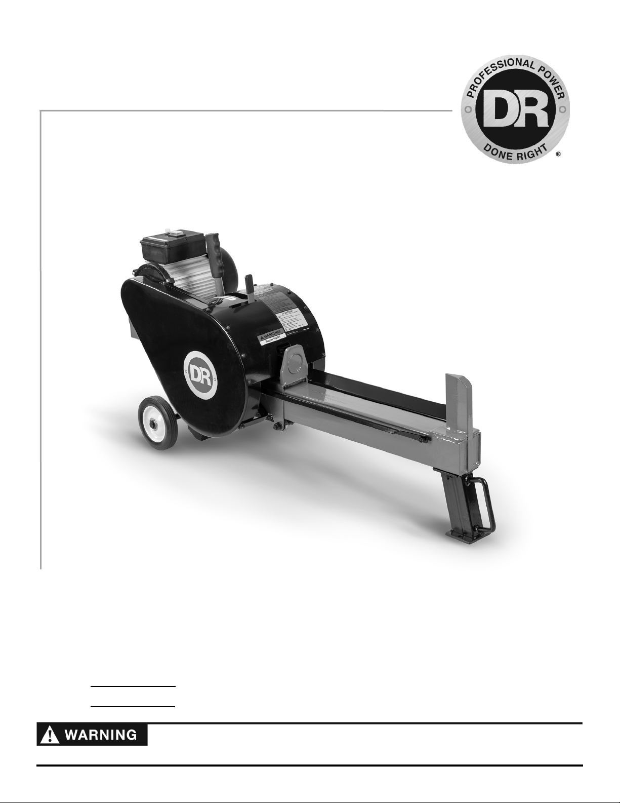
K10 RAPIDFIRE™ LOG SPLITTER
SAFETY & OPERATING INSTRUCTIONS
Model:
K10
Serial No.
Order No.
Read and understand this manual and all instructions before operating the DR K10 RAPIDFIRE LOG SPLITTER.
DR Power Equipment
Toll-free phone: 1-800-DR-OWNER (376-9637)
Website: www.DRpower.com

Table of Contents
Chapter 1: General Safety Rules ............................................................................................................................................................ 3
Chapter 2: Setting Up the DR K10 RAPIDFIRE LOG SPLITTER ........................................................................................................... 7
Chapter 3: Operating the DR K10 RAPIDFIRE LOG SPLITTER ........................................................................................................... 9
Chapter 4: Maintaining the DR K10 RAPIDFIRE LOG SPLITTER ........................................................................................................ 12
Chapter 5: Troubleshooting .................................................................................................................................................................. 16
Chapter 6: Parts Lists and Schematic Diagrams .................................................................................................................................. 18
Conventions used in this manual
This indicates a hazardous situation, which, if not avoided, could result in death or serious injury.
This indicates a hazardous situation, which, if not avoided, could result in minor or moderate injury.
This information is important in the proper use of your machine. Failure to follow this instruction could result in damage to
your machine or property.
Serial Number and Order Number
A Serial Number is used to identify your machine and is located on the Serial Number Label on your machine. An Order Number
is used to check and maintain your order history and is located on your packing slip. For your convenience and ready reference,
enter the Serial Number and Order Number in the space provided on the front cover of this manual.
Additional Information and Potential Changes
DR Power Equipment reserves the right to discontinue, change, and improve its products at any time without notice or obligation
to the purchaser. The descriptions and specifications contained in this manual were in effect at printing. Equipment described
within this manual may be optional. Some illustrations may not be applicable to your machine.
California Proposition 65
2 DR® K10 RAPIDFIRE™ LOG SPLITTER
Chapter 1: General Safety Rules
Read this Safety & Operating Instructions manual before you use the DR RAPIDFIRE LOG SPLITTER. Become familiar with the
operation and service recommendations to ensure the best performance from your machine. If you have any questions or need
assistance, please contact us at www.DRpower.com or call toll-free 1-800-DR-OWNER (376-9637) and one of our Technical
Support Representatives will be happy to help you.
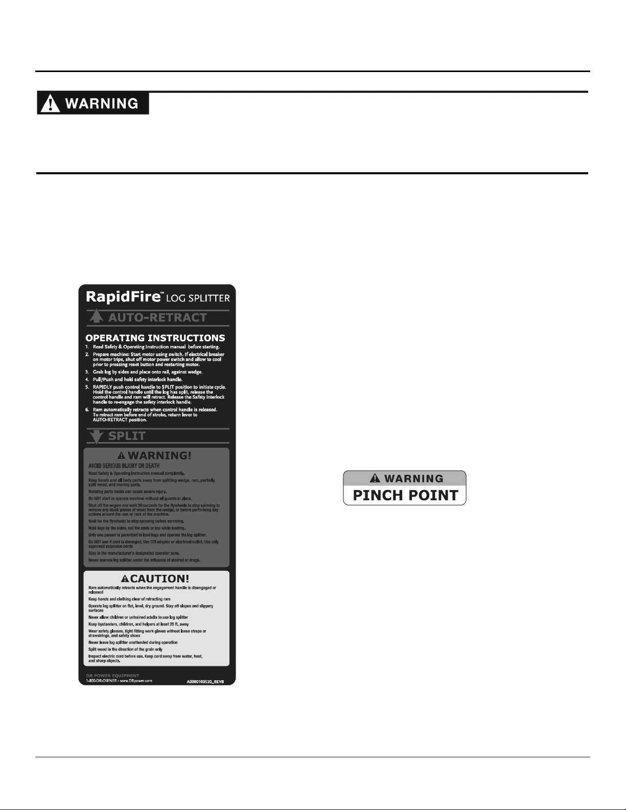
Labels
Your DR K10 RAPIDFIRE LOG SPLITTER carries prominent labels as reminders for its proper and safe use. Shown below are
copies of all the Safety and Information labels that appear on the equipment. Take a moment to study them and make a note of
their location on your LOG SPLITTER as you set up and before you operate the unit. Replace damaged or missing safety and
information labels immediately.
#A0000103520
#25044
CONTACT US AT www.DRpower.com 3

Protecting Yourself and Those Around You
This is a high-powered machine, with moving parts operating with high energy. You must operate the machine safely. Unsafe
operation can create a number of hazards for you, as well as anyone else in the nearby area. Always take the following precautions
when using this machine:
Keep in mind that the operator or user is responsible for accidents or hazards occurring to other people, their property, and
themselves.
Always wear protective goggles or safety glasses with side shields while using the Log Splitter to protect your eyes from
possible thrown debris.
Avoid wearing loose clothing or jewelry, which can catch on moving parts.
We recommend wearing gloves while using the Log Splitter. Be sure your gloves fit properly and do not have loose cuffs or
drawstrings.
Wear shoes with non-slip treads when using your Log Splitter. If you have safety shoes, we recommend wearing them. Do
not use the machine while barefoot or wearing open toed sandals.
Wear long pants while operating the Log Splitter.
Use ear protectors or ear plugs rated for at least 20 dba to protect your hearing.
Keep bystanders at least 50 feet away from your work area at all times. Stop the motor when another person or pet
approaches.
Safety for Children and Pets
Tragic accidents can occur if the operator is not alert to the presence of children and pets. Children are often attracted to the
machine and the splitting activity.
precautions:
Never
assume that children will remain where you last saw them. Always follow these
Keep children and pets at least 50 feet from the working area and ensure they are under the watchful care of a responsible
adult.
Be alert and turn the machine off if children or pets enter the work area.
Never allow children to operate the Log Splitter.
4 DR® K10 RAPIDFIRE™ LOG SPLITTER

Safety with Electric - Powered Machines
Never overlook the hazards of electricity. Always follow these precautions:
Never open the switch box or motor cover. Never attempt any electrical repairs yourself. If in doubt, consult a qualified
electrician, visit our website at www.DRpower.com or contact DR Power Equipment for toll-free support at: 1-800-dr-owner
(376-9637) for help or information.
Never use an extension cord that is not rated for outdoor use.
Never operate the Log Splitter if there is an electrical hazard present.
Never operate the Log Splitter in wet conditions and always store under cover.
Never operate the Log Splitter with a damaged electrical cord or damaged extension cord.
Never pull on the electrical cord to move the machine.
Always grasp the electrical cord plug when unplugging the cord from the outlet; never pull the plug out by the cord. Make
sure your fingers do not touch the metal prongs when plugging or unplugging.
Never operate the Log Splitter unless the electrical cord is plugged into a properly grounded GFCI protected electrical outlet,
which supplies 110-120v power, and is protected by a 20-amp circuit breaker.
Never tamper with safety devices. Check their proper operation regularly.
If you are using an extension cord, keep the connection between the electrical cord and the extension cord well away from any
water.
Never use an extension cord longer than 25 feet and smaller than 12 awg in diameter, or longer than 50 feet and smaller than
10 awg in diameter; the cord will produce a voltage drop that will prevent the motor from supplying full power and may cause
damage to the motor. Use of a smaller diameter (larger awg number) extension cord could result in melting of the insulation
or even create a fire.
Always keep the electrical cord and/or extension cord away from excessive heat, oil, and sharp objects.
CONTACT US AT www.DRpower.com 5

General Safety
Operating this Log Splitter safely is necessary to prevent or minimize the risk of death or serious injury. Unsafe operation can
create a number of hazards for you. Always take the following precautions when operating this Log Splitter:
Your Log Splitter is a powerful tool, not a plaything. Exercise extreme caution at all times. The machine is designed to split
logs. Do not use it for any other purpose.
Know how to stop the Log Splitter quickly; see “stopping the motor” in chapter 3.
Never operate your unit on a slippery, wet, muddy, or icy surface. Exercise caution to avoid slipping or falling.
See manufacturer’s instructions for proper operation and installation of accessories. Only use accessories approved by DR
Power Equipment.
Never use the machine without ensuring that all guards and shields are in place.
Never, under any conditions, remove, bend, cut, fit, weld, or otherwise alter standard parts on the Log Splitter. This includes
all shields and guards. Modifications to your machine could cause personal injuries and property damage and will void your
warranty.
Allow only one person to operate the Log Splitter at any time. This includes placing the log on the beam.
If the machine should start making an unusual noise or vibration, Shut off the Motor, Unplug the Power Cord. Wait 5
minutes for machine to cool down then inspect for damage. Vibration is generally a warning of trouble. Check for damaged
parts and clean, repair and replace as necessary.
Never tamper with safety devices. Check their proper operation regularly.
Before performing any maintenance or inspection procedure on the Log Splitter, Shut off the Motor, Unplug the Power Cord.
Wait 5 minutes for machine to cool down.
Never allow people who are unfamiliar with these instructions to use the Log Splitter. Allow only responsible individuals who
are familiar with these rules of safe operation to use your machine.
Never overload or attempt to split logs beyond the recommendations listed in this manual. Personal injury or damage to the
machine could result.
While using the Log Splitter, don't hurry or take things for granted. When in doubt about the equipment or your surroundings
stop the machine and take the time to look things over.
Never operate the machine when under the influence of alcohol, drugs, or medication.
Use the machine only in daylight.
Stay alert for hidden hazards or traffic.
Keep all nuts and bolts tight and keep the equipment in good operating condition.
A Note to All Users
No list of warnings and cautions can be all-inclusive. If situations occur that are not covered by this manual, the operator must
apply common sense and operate this DR K10 RAPIDFIRE LOG SPLITTER in a safe manner. Contact us at www.DRpower.com or
call 1-800-DR-OWNER (376-9637) for assistance.
6 DR® K10 RAPIDFIRE™ LOG SPLITTER
Chapter 2: Setting Up the DR K10 RAPIDFIRE LOG SPLITTER
r
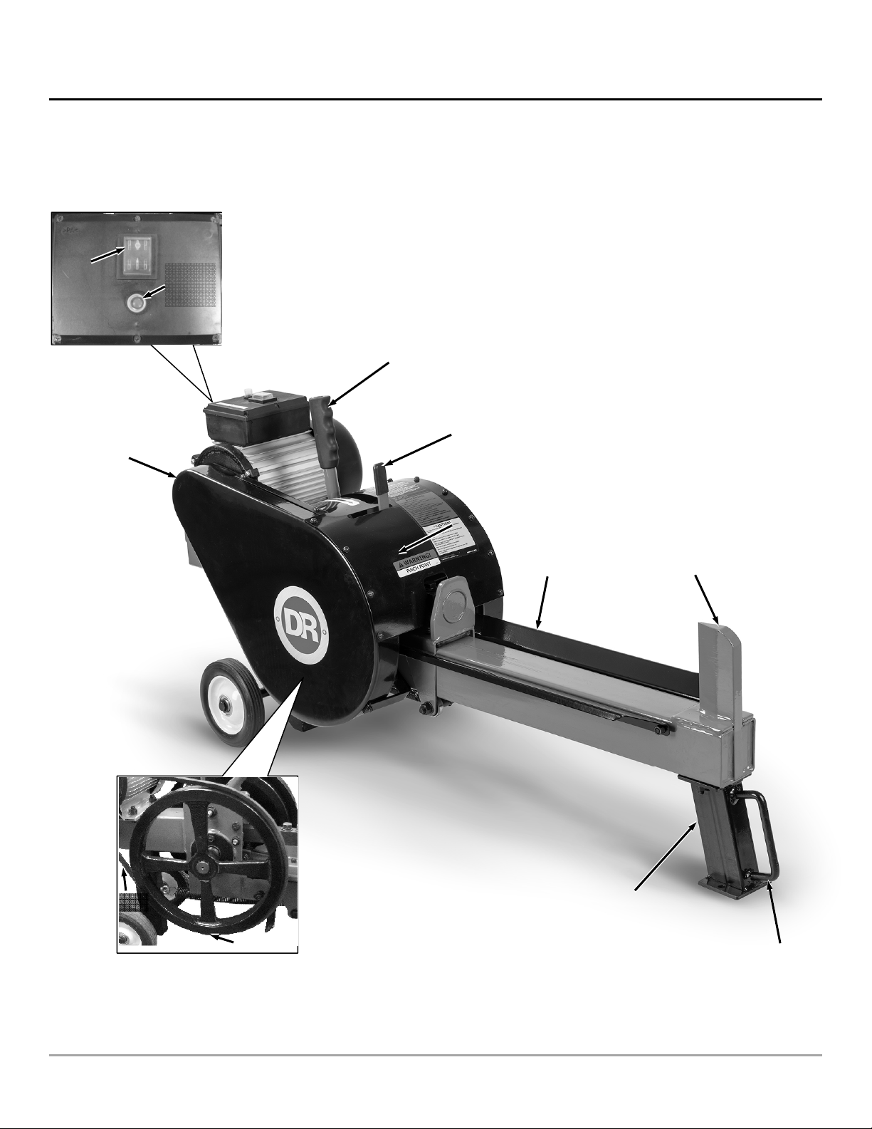
It may be helpful to familiarize yourself with the controls and features of your DR K10 RAPIDFIRE LOG SPLITTER as shown in
Figure 1 before beginning these procedures. If you have any questions at all, please feel free to contact us at www.DRpower.com.
DR K10 RAPIDFIRE LOG SPLITTER Controls and Features
ON/ OFF
Switch
Belt Guard
Circuit
Breaker
Switch
Engagement
Handle
Two Hand
Operation
Leve
Ram
Cradle
Splitting Wedge
Belt
Flywheel
Figure 1
Frame Stand
Handle
CONTACT US AT www.DRpower.com 7
Specifications
@
r
HP 2
Output Torque .025 in-lbs
Voltage 110
Full Load Current (Amps) 14.5
Power (Watts) 1060
Hertz 60
Phase 1
Overload Protection Thermal Breaker
Outlet Cord 6'
Frame Gauge 3mm
Belt Size A-1180
Flywheel Weight (lbs.) 13
Flywheel RPM 490
Maximum Log Length 16"
Maximum Log Diameter* 12"
Cycle Time (sec.) 1
Splitting Ability Out splits 10 ton Hydraulic
Wedge Height 5"
Wheel size 6"
Machine Height 24.5"
Machine Length 49"
Machine Width 11.875"
Weight 132
*The diameter listed is indicative of the maximum suggested size. A small log can be difficult to split when it contains knots or a
particularly tough fiber. On the other hand, it may not be difficult to split logs with regular fibers even if its diameter exceeds the
maximum indicated above.
Full Load
Assembling the DR K10 RAPIDFIRE LOG SPLITTER
Tools needed:
14mm Wrench
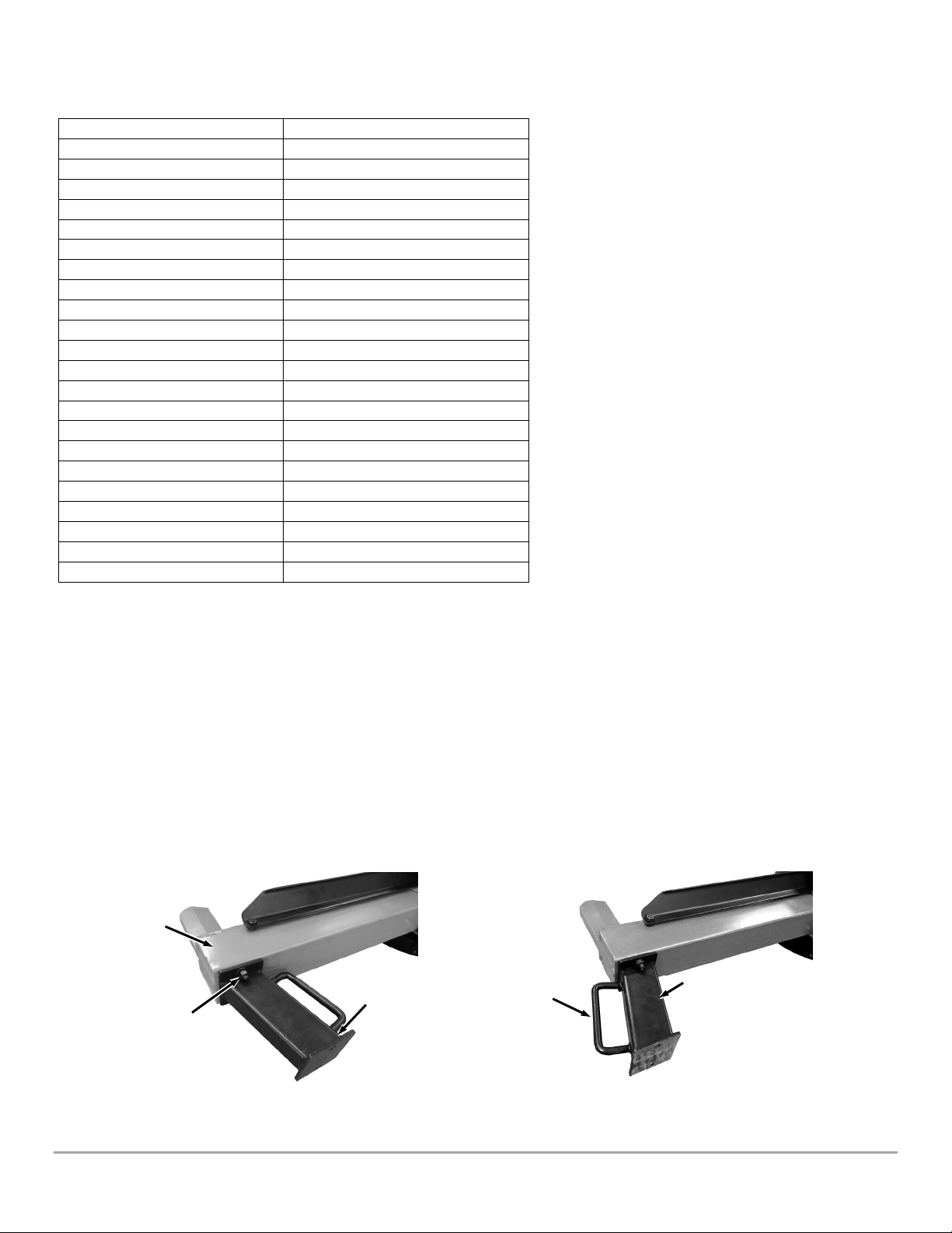
Note: The Frame Stand comes on the machine but needs to be rotated 180 degrees to be in the operating orientation.
1. Use a 14mm Wrench to remove the two Nuts and Lock Washers that hold the Frame Stand onto the Frame (Figure 2).
2. Remove the Frame Stand and rotate it 180 degrees. Reinstall it with the handle on the outside using the Nuts and Lock
Washers removed in step 1 (Figure 3).
Frame
Frame
Nut and
Lock Washe
( 1 per side)
Figure 2
Frame
Stand
Handle
Figure 3
Stand
8 DR® K10 RAPIDFIRE™ LOG SPLITTER

Chapter 3: Operating the DR K10 RAPIDFIRE LOG SPLITTER
It may be helpful to better familiarize yourself with the features of your Log
Splitter by reviewing Figure 1 in Chapter 2 before beginning the steps outlined in
this chapter.
Read and understand all instructions, safety precautions, and/or
warnings listed in “Chapter 1 General Safety Rules” before operating this
DR K10 RAPIDFIRE LOG SPLITTER. If any doubt or question arises
about the correct or safe method of performing anything found in this
manual, please contact our Customer Service Representatives at our toll
free number: 1-800-DR-OWNER (376-9637).
When operating the Log Splitter, make sure you are standing in the safe
operating area (OPERATOR ZONE) as shown in Figure 4. You must stay
in the safe operating areas at all times when the ram is in motion
(whether extending or retracting). Never place any part of your body into
a position that causes an unsafe operating condition.
Operator
Zone
Operator
Zone
Figure 4
CONTACT US AT www.DRpower.com 9

Figure 5
Circuit
Breaker
Switch
On/ Off
Switch
K 10 Operation
Refer to the “Safety with Electric - Powered Machines” section in Chapter 1
before using the Electric Motor for safety warnings and specific power and
connection requirements.
Starting the Motor
1. Position your Log Splitter on a flat, dry surface and chock the Wheels or
screw down the Frame Stand to prevent the Splitter from moving during
use.
2. Make sure the Log Splitter is plugged into a properly grounded 20 Amp,
GFCI protected outlet.
3. Push the red Toggle Switch to the on position (Figure 5).
Stopping the Motor
1. Push the red Toggle Switch to the off position to shut the Motor off (Figure
5).
Note: Unplug the Power Cord when not using the Splitter.
Resetting the Circuit Breaker
If the Motor will not run when the power Switch is turned on and power is
connected to the machine, the Circuit Breaker Switch may need resetting. Read
all instructions in the “Safety with Electric - Powered Machines” section in
Chapter 1 to eliminate the typical causes for Circuit Breaker activation.
Figure 6
Figure 7
1. Push the Circuit Breaker Switch in to reset (Figure 5).
Splitting Logs
Note: All logs should be no longer than 16". Refer to the following photos for the
correct and incorrect methods of splitting logs. Never split a log using an incorrect or
unsafe method.
Do not place your hands on the ends of the log when loading the Log
Splitter. This is a very UNSAFE method and could result in injury to your
hands (Figure 6).
Do not reach or step across the beam while the Log Splitter is running.
This is a very UNSAFE method which could cause personal injury or even
death.
Never attempt to split wood across the grain. The Log Splitter was not
designed for cross-grain splitting. Doing so could damage the Log
Splitter and may cause personal injury (Figure 7).
Make sure both ends of the log you are splitting are cut as square as
possible. This will prevent the log from sliding out of position while under
pressure (Figure 8).
Figure 8
10 DR® K10 RAPIDFIRE™ LOG SPLITTER

2
THE RAPIDFIRE LOG SPLITTER OPERATES DIFFERENTLY THAN A
HYDRAULIC SPLITTER. NOT OPERATING THE MACHINE PROPERLY WILL
RESULT IN DAMAGE TO THE MACHINE. ALWAYS FOLLOW THESE
NOTICES:
Do not be timid. A rapid movement of the Engagement Handle is
necessary for the Rack and Pinion to engage and disengage fully without
damage.
The Engagement Handle should never be stopped in any location
between the fully forward or fully backward positions.
Do not hold the Handle in the forward position when the Ram stops
moving forward. Always pull the Engagement Handle RAPIDLY to the
back (Auto-Retract) position as soon as the Log is split or when the Ram
is at the end of the stroke or when the Ram stops moving forward due to
a tough log.
Wood against
Wedge
Figure 9
Two Hand
Operation
Handle
Hands on Sides
of Wood
Engagement
Handle
1. Place the log on the Log Splitter. Grasp the log on the sides near the middle
of the block (Figure 9). Center the log, side-to-side, on the rail of the Log
Splitter, making sure that one end is against the Splitting Wedge.
The engagement Handle must be held fully in the Split Position against
the hard stop when splitting. Failure to do so may result in kickback of
the Handle.
2. With one hand, actuate and hold the Two Hand Operation Handle towards
you, then RAPIDLY actuate the Engagement Handle fully towards the Motor
until it contacts the hard stop and hold firmly until the Ram stops (Figure
10).
3. IMMEDIATELY AFTER the log is split, actuate and hold the Engagement
Handle to the Auto-Retract position to allow the Ram to return. If the Ram
stops before the end of the stroke while splitting a tough log, quickly actuate
the Engagement Handle back to the Auto-Retract position.
Splitting Tough Logs
If the Ram stops before the end of the stroke while splitting a tough Log, quickly
actuate the Engagement Handle back to the Auto-Retract position. Let the Ram
return and allow the Flywheels to gain momentum for another full power split.
1
Figure 10
CONTACT US AT www.DRpower.com 11

Chapter 4: Maintaining the DR K10 RAPIDFIRE LOG SPLITTER
Regular maintenance is the way to ensure the best performance and long life of your machine. Please refer to this manual for
proper maintenance procedures.
Before performing any maintenance procedure or inspection, stop the motor, unplug the power cord and wait five (5) minutes to
allow all parts to cool.
Regular Maintenance Checklist
PROCEDURE BEFORE EACH
USE
Check General Equipment Condition
Perform Rail Maintenance
Check Belt
Check the condition of the electrical cord.
Grease Rack
Clean Motor Exterior and Cooling Fins
▲
▲
▲
▲
▲
Lubrication
Top of Rail
Figure 11
All Bearings of your Splitter are sealed units and should have sufficient lubricant
to last the life of your machine with normal use. Perform machine lubrication
per the following instructions.
Rail Maintenance
Between each use of the LOG SPLITTER, we recommend removing any debris
caught on the Rail or Ram and applying a rust preventative (Fluid Film or
equivalent) to any bare metal areas on the top of the Rail (Figure 11). This will
assure the smoothest return action of the Ram.
E
VERY 5
HOURS
▲
E
VERY 25
HOURS
12 DR® K10 RAPIDFIRE™ LOG SPLITTER

Greasing the Rack
r
Note: It is important to grease the Rack every 5 hours for proper operation.
Tools and Supplies needed:
General Purpose Grease
Clean Rags
Phillips Screwdriver
1. Use a Phillips Screwdriver to remove the 11 Guard Screws, Washers and
Lock Washers that secure the Center Guard (Figure 12).
2. Remove the Guard Screws, Washers and Lock Washers that secure the
Flywheel and Belt Guard.
3. Disconnect the Return Spring from the Eye Bolt on the Frame (Figure 13).
Right Side
Flywheel Cover
Bracket
Screws
(Qty 2 each side)
Figure 12
Right Side Belt Cover
(Qty 2 Screws)
Center Cover Screw to Frame
(Qty 1 Screw)
Left Side
Flywheel
Cover with
Center Cove
Center Cover
Screws (Qty 4)
4. Pull the Rack out and grease the Rack Teeth, top side of the Rack and the
Pinion (Figure 14).
5. Push the Rack back in and reinstall the Return Spring to the Eye Bolt when
finished greasing.
6. Reinstall the Guards.
Figure 13
Figure 14
Eye Bolt
Pinion
Return Spring
Rack
Teeth
CONTACT US AT www.DRpower.com 13

Straight Edge
Pulley
Figure 15
Tension Nut
Motor Hardware
(2 per side)
Figure 16
1/2"-5/8"
Flywheel
Belt
Adjusting and Replacing the Belt
Checking and Adjusting the Belt Tension
Tools and Supplies needed:
Phillips Screwdriver
14mm Wrench
17 mm Wrench
1. Remove the Center Guard, Flywheel Guard, and Belt Guard (see “Greasing
the Rack” in this Chapter).
2. Place a Straight Edge across the top of the belt (Figure 15).
3. Push on the top of the Belt with about 10 pounds of pressure. The Belt
should deflect approximately 1/2" to 5/8". If the distance is not between
1/2" and 5/8", adjust per the following directions.
4. Loosen the Motor Hardware using a 14mm Wrench on the bolt and a 17mm
Wrench on the nut (Figure 16).
5. Use a 17mm Wrench to turn the Tension Nut in against the Frame to tighten
(if Belt is too loose) or out to loosen (if Belt is too tight) for the correct Belt
tension.
Note: The Belt performs best with a slight amount of slack to allow the belt to slip
on the pulley when the Wedge encounters a tough log. Too much tension may stall
the Motor.
6. When the Belt is at the proper tension, tighten the Motor Hardware.
7. Reinstall the Guards.
Replacing the Belt
Tools and Supplies needed:
Phillips Screwdriver
14mm Wrench
17 mm Wrench
DR Belt
1. Remove the Center Guard, Flywheel Guard, and Belt Guard (see “Greasing the Rack” in this Chapter).
2. Loosen the Motor Hardware using a 14mm Wrench on the bolt and a 17mm Wrench on the nut (Figure 16).
3. Use a 17mm Wrench to loosen the Tension Nut until the Belt can be easily removed.
4. Install a new Belt onto the Pulley and Flywheel (Figure 15).
5. Tighten the Tension Nut against the Frame and follow the steps in the “Checking and Adjusting the Belt Tension” section to
set the Belt tension.
6. Tighten the Motor Hardware.
7. Reinstall the Guards.
14 DR® K10 RAPIDFIRE™ LOG SPLITTER

Adjusting the Steel Bushing Over Center
A
Only perform this adjustment if your Engagement Handle is kicking back excessively when splitting a log. If you confirm that the
Engagement handle is adjusted properly as shown in Figure 17, there may be another issue. If you have any questions, contact us
at www.DRpower.com or call 1-800-DR-OWNER (376-9637) for assistance.
Tools needed:
14mm Wrench
Two 17mm Wrenches
Phillips Screwdriver
1. Remove the Center Guard, Flywheel Guard, and belt Guard (see “Greasing
the Rack” in this Chapter).
2. Push the Two Hand Operation Lever to the side and move the Engagement
Handle forward until it contacts the Vertical Adjustment Bolt (Figure 17).
Note: You May have to pull out on the Ram so that the Teeth on the Rack and
Pinion line up.
3. Use a 17mm Wrench to loosen the Locking and Handle Retention Nuts on
the Vertical Adjustment Bolt.
Vertical
djustment
Bolt
Locking
Nut
Figure 17
Engagement
Handle
1°-3°
Handle Retention
Nut
Do not adjust more than 1-1/4 revolutions when adjusting off center.
Adjustments too far off center will not allow the Rack Teeth to engage fully
Two Hand
Operation
Handle
2mm Gap
and will cause damage to the Splitter.
4. Use a 14mm Wrench to adjust the Vertical Adjustment Bolt so the
Engagement Handle is approximately 1 to 3 degrees off center towards the
Vertical Adjustment Bolt.
The Engagement Handle must move just past center as it contacts the
Vertical Adjustment Bolt. If it is at the center position, or off center in the
wrong direction, the force of splitting a log will be transferred through the
Stopping
Bolt
Figure 18
Nut and
Lock Washer
Engagement
Handle
Engagement Handle and could cause injury.
5. Use a 17mm Wrench to tighten the Locking Nut and Handle Retention Nut. Make sure the Two Hand Operation Handle is
able to move freely and return to the locked position. If the Handle cannot move freely, loosen the Handle Retention Nut 1/4
rotation at a time until it can move freely.
6. Push the Engagement Handle all the way to the Return Position then back into the Split Position to confirm the Steel Bushing
is moving just past center.
7. Check the gap at the end of the Stopping Bolt and the Engagement handle (Figure 18). The gap should be approximately 2mm.
If the gap needs adjustment, hold the head of the Bolt using a 17mm Wrench and loosen the Nut using another 17mm
Wrench. Adjust the Bolt as needed to correct the gap and retighten the Nut against the Two hand Operation Handle.
8. Reinstall the Guards.
When using the Splitter for the first time after this adjustment, split smaller diameter logs with no knots to verify that the
adjustments are correct before trying larger diameter tougher logs.
If you have any questions please contact us at www.DRpower.com or call 1-800-DR-OWNER (376-9637) for assistance.
CONTACT US AT www.DRpower.com 15

Chapter 5: Troubleshooting
Most problems are easy to fix. Consult the Troubleshooting Table below for common problems and their solutions. If you
continue to experience problems, contact us at www.DRpower.com or call toll-free 1-800-DR-OWNER (376-9637) for support.
Before performing any maintenance procedure or inspection, stop the electric motor, wait five minutes to allow all parts to cool.
Disconnect the power cord from the source of Electricity.
Troubleshooting Table
SYMPTOM POSSIBLE CAUSE
The Motor does not run
Motor Reset
continuously trips
Log fails to split.
Rack returning very slow
or not returning
properly.
Operator Lever snapping
out of gear or not
staying in gear.
With Motor running and
the handle is pushed,
the ram does not move
or is slow to respond.
Splitter unplugged; plug Splitter in.
Splitter Cord may be damaged; visit our website at www.DRPower.com or call 1-800-DR-
OWNER (376-9637) for assistance.
The motor Reset has tripped; push the Reset Button.
If the above causes are not the problem, a circuit breaker might need to be reset; Reset Circuit
Breaker.
If the Motor still does not run, visit our website at www.DRPower.com or call 1-800-DR-
OWNER (376-9637) for assistance.
Make sure the voltage at the outlet or extension cord connection to the Splitter is 110-
120VAC.
If you are using an extension cord, make sure that the cord is no more than 25 feet long, is
not smaller than 12 AWG wire or no more than 50 feet long, and is not smaller than 10 AWG
wire.
The Belt is too tight. Check the Belt Tension and adjust to allow for slipping.
Incorrect positioning of the log; re-position the log flat on the splitting beam with the end
squarely against the Wedge.
Log exceeds permitted dimensions, or the wood is too hard for the capacity of the machine.
The maximum log length is 16" with a maximum diameter of 12" for the Splitter
Check for wood chips or debris between ram and rail. Clean beam of built up/caked on
debris.
Check rack lift bearing for alignment or damage.
Check interference between Ram and Tray.
Return spring is unhooked or damaged. Reconnect or replace as needed.
Lever not all the way in the Split Position when rack comes under full load. Push lever quicker
and more forcefully into the full Split Position. A hard stop should be felt at the end of the
stroke when engaging the handle.
Vertical adjustment is not adjusted correctly. See the “Adjusting the Steel Bushing over
Center” section in Chapter 4.
Ram has been overloaded at lower part of face. Check rack gear for straightness.
Make sure the voltage at the outlet or extension cord connection to the Splitter is 110-
120VAC.
If you are using an extension cord, make sure that the cord is no more than 25 feet long, is
not smaller than 12 AWG wire or no more than 50 feet long, and is not smaller than 10 AWG
wire.
If the Wedge will still not move or is slow to respond, Visit our website at www.DRPower.com,
or call 1-800-DR-OWNER (376-9637) for assistance.
16 DR® K10 RAPIDFIRE™ LOG SPLITTER

Troubleshooting Table (Continued)
Before performing any maintenance procedure or inspection, stop the electric motor, wait five minutes to allow all parts to cool.
Disconnect the power cord from the source of Electricity.
SYMPTOM POSSIBLE CAUSE
Rack slamming back too
fast.
Wedge end of machine too high. Must be almost level with ram end or just slightly higher.
Springs not operating properly. Fix or replace as needed.
Machine does not seem
to have full splitting
power.
Operator Lever not
engaging rack with
pinion gear.
Rack not disengaging
from pinion when
handle is released
The belt may be too loose. Adjust or replace belt as needed.
Clean wood chips or other debris from under rack.
Clean accumulated dirt from frame where carriage assembly rests against rubber bumpers.
Belt must be loosened to allow for slipping while disengaging
CONTACT US AT www.DRpower.com 17

Chapter 6: Parts Lists and Schematic Diagrams
Parts List – Flywheel and Cover Assembly
NOTE: Part numbers listed are available through DR Power Equipment.
Ref# Part# Description
72 353971 Leg Assembly
73 361031 Nut, Finish, M8, ZP
74 337431 Washer, Lock, M8
75 A0000381386 Frame, Forward Handle w/Labels
76 364291 Bolt, HCS, M8 - 1.25 mm X 110 mm, CL
8.8, ZP
77 337431 Washer, Lock, M8
78 361031 Nut, Finish, M8, ZP
79 354051 Cradle, Log
80 354061 Spacer, Cradle, Log
81 302601 Bolt, HCS, M8-1.25 X 100 mm, CL 8.8, ZP
82 361031 Nut, Finish, M8, ZP
82-1 337431 Washer, Lock, M8
83 337031 Bolt, HCS, M8-1.25 X 25 mm, CL 8.8, ZP
83-1 337431 Washer, Lock, M8
83-2 361031 Nut, Finish, M8, ZP
97 387701 Cover, Flywheel, Right, w/Labels
98 354031 Bracket, Cover
Ref# Part# Description
84 354081 Key, Flywheel, 8 mm X 7 mm X 20 mm
85 353991 Pinion
86 387691 Cover, Flywheel, Left, w/Labels
87 337031 Bolt, HCS, M8-1.25 X 25 mm, CL 8.8, ZP
87-1 337431 Washer, Lock, M8
87-2 361031 Nut, Finish, M8, ZP
88 353911 Flange, Bearing
89 353921 Flywheel
89-1 363181 Screw, Set, M8 X 1.0 X 8mm
90 361011 Snap Ring, External, 24 mm X 1.2 mm
91 360931 Bearing, Roller, 30mm X 55mm X 13mm
92 363251 Screw, M5-.8 mm X 10 mm
93 364321 Washer, Flat, M5
93-1 364331 Washer, Split-Lock, M5
94 364271 Belt, A1180
95 A0000381387 Cover, Center, w/Labels
96 364371 Cover, Belt, Right, Small
18 DR® K10 RAPIDFIRE™ LOG SPLITTER

Schematic – Flywheel and Cover Assembly
CONTACT US AT www.DRpower.com 19

Parts List – Frame and Motor Assembly
Note: Part numbers listed are available through DR Power Equipment.
Ref# Part# Description
1 36095 Motor, 1060w
2 36108 Key, 6mm X 6mm X 25mm
3 36427 Pulley, Single Belt, 51mm X 19mm
3-1 37202 Bolt, Hcs, M8-1.25 Mm X 15 Mm, Cl 8.8, Zp
3-2 33743 Washer, Lock, M8
3-3 29251 Washer, Flat, M8
4 364221 Bolt, HCS, M10 - 1.50 mm X 30 mm, CL 8.8,
ZP
5 302501 Washer, M10
6 364231 Washer, Split-Lock, M10
7 303591 Nut, Hex, M10-1.5
8 360911 Spring, Return, 2 Hand Op
9 364241 Bolt, HCS, M10 X 75mm, CL 8.8, ZP
10 360871 Bolt, HCS, M10 X 50mm, CL 8.8, ZP
11 303591 Nut, Hex, M10-1.5
12 364231 Washer, Split-Lock, M10
13 302491 Nut, Locking, M10
14 A0000322112 Handle, Forward Two-Hand Op
14-1 360891 Cover, Handle Grip, 2 Hand Op
15 360901 Cover, Handle Grip, Actuation
16 A0000322111 Handle - Forward Actuation
16-1 A0000322117 Spring, Actuation Handle
17 A0000322483 Cord, Power
18 A0000322477 Box - Electrical
18-1 A0000381388 Cover - Electrical Box w/Labels
18-2 A0000322946 Capacitor - 50 Uf 250 Vac
18-3 A0000322948 Switch - Rocker
18-4 A0000322949 Screw - #6 X 5/8" Pan Head
18-5 A0000322951 Screw - M4 X 10mm Pan Head W/ Washer
18-6 A0000322953 Fuse
19 303591 Nut, Hex, M10-1.5
19-1 302501 Washer, M10
19-2 364231 Washer, Split-Lock, M10
20 A0000381394 Bolt, HCS, M10 - 1.50 mm X 105 mm, CL
12.9, ZP
20-1 360991 Bolt, HCS, M10 - 1.50 mm X 110 mm, CL
12.9, ZP
21 364251 Bolt, HCS, M12 - 1.75 mm X 50 mm, CL 8.8
ZP
22 364351 Bushing, Handle
23 302521 Washer, M12
24 303591 Nut, Hex, M10-1.5
25 364361 Nut, Finish, M12, ZP
26 364221 Bolt, HCS, M10 - 1.50 mm X 30 mm, CL 8.8,
ZP
27 303591 Nut, Hex, M10-1.5
28 364231 Washer, Split-Lock, M10
29 392801 Roller Assembly, Spring, 2 Bolt
31 361021 Bolt, Carriage, M10 - 1.50 mm X 50 mm, CL
8.8, ZP
Ref# Part# Description
32 303591 Nut, Hex, M10-1.5
33 364231 Washer, Split-Lock, M10
34 363241 Bearing, Lift, 10 mm X 22 mm X 6 mm
34-1 394961 Spacer, Lift, Rack
35 360871 Bolt, M10 X 30 mm, CL 8.8, ZP
36 303591 Nut, Hex, M10-1.5
36-1 364231 Washer, Split-Lock, M10
37 36106 Spring, Ram, Lifter
38 392811 Bolt, SHCS, M8-1.25 x 16mm
38-1 337431 Washer, Lock, M8
39 354151 Rack
40 364261 Bolt, HCS, M12 - 1.25 mm X 60 mm
41 360981 Washer, Split-Lock, M12
42 30252 Washer, M12
43 39279 Ram Assembly
44 36434 Nut, Finish, M5
45 36433 Washer, Split-Lock, M5
45-1 36432 Washer, Flat, M5
46 35420 Slider
47 36431 Bolt, SH Counter Sink, M5-.8 mm X 20 mm,
ZP
48 30359 Nut, Hex, M10-1.5
49 30250 Washer, M10
49-1 36423 Washer, Split-Lock, M10
50 36086 Bearing, Roller, 10 mm X 25 mm X 11 mm
51 30250 Washer, M10
52 36096 Spacer, Ram
53 36099 Bolt, HCS, M10 - 1.50 mm X 110 mm, CL
12.9, ZP
54 36327 Pin, Roll, 3 mm X 20 mm
55 30361 Washer, Flat, M16
56 35409 Wheel
57 37201 Spring, Return
58 35394 Mount Assembly, Axle
59 36105 Tension, Belt
60 30359 Nut, Hex, M10-1.5
61 33743 Washer, Lock, M8
62 36104 Bumper, Ram Stop
63 36103 Nut, Finish, M8, Zp
64 29251 Washer, Flat, M8
67 30250 Washer, M10
68 30359 Nut, Hex, M10-1.5
69 36423 Washer, Split-Lock, M10
Not Illustrated
A0000103520 Label, Warning, Operator
36321 Label Branding
25044 Label, Warning, Pinch Point, 3.5x1
35187 Label, 5" Silver DR
20 DR® K10 RAPIDFIRE™ LOG SPLITTER

Schematic – Frame and Motor Assembly
CONTACT US AT www.DRpower.com 21

Notes:
22 DR® K10 RAPIDFIRE™ LOG SPLITTER

DR
®
K10 RAPIDFIRE™ LOG SPLITTER
2-Year Limited Warranty
Terms and Conditions
The DR
workmanship when put to ordinary and normal consumer use; ninety (90) days for any other use.
For the purposes of all the above warranties, “ordinary and normal consumer use” refers to non-commercial
residential use and does not include misuse, accidents, or damage due to inadequate maintenance.
DR
product of this type is used. DR Power Equipment however, limits the implied warranties of merchantability and
fitness in duration to a period of two (2) years in consumer use, ninety (90) days for any other use.
The 2-Year Limited Warranty on the DR
our factory. The 2-Year Limited Warranty is applicable only to the original owner.
K10 RAPIDFIRE™ LOG SPLITTER is warranted for two (2) years against defects in materials or
Power Equipment certifies that the DR
K10 RAPIDFIRE™ LOG SPLITTER is fit for ordinary purposes for which a
K10 RAPIDFIRE™ LOG SPLITTER starts on the date the machine ships from
The warranty holder is responsible for the performance of the required maintenance as defined by the manufacturer's
owner's manuals. The warranty holder is responsible for replacement of normally wearing parts such as the Drive
Belt. This warranty does not cover attachments and accessories to the machine.
During the warranty period, the warranty holder is responsible for the machine transportation charges, if required.
During the warranty period, warranty parts will ship by standard method at no charge to the warranty holder.
Expedited shipping of warranty parts is the responsibility of the warranty holder.
SOME STATES DO NOT ALLOW LIMITATIONS ON THE LENGTH OF IMPLIED WARRANTIES, SO THE ABOVE
LIMITATIONS MAY NOT APPLY TO YOU.
DR
Power Equipment shall not be liable under any circumstances for any incidental or consequential damages or
expenses of any kind, including, but not limited to, cost of equipment rentals, loss of profit, or cost of hiring services
to perform tasks normally performed by the DR
SOME STATES DO NOT ALLOW THE EXCLUSION OR LIMITATION OF INCIDENTAL OR CONSEQUENTIAL
DAMAGES, SO THE ABOVE LIMITATIONS MAY NOT APPLY TO YOU.
THIS WARRANTY GIVES YOU SPECIFIC LEGAL RIGHTS, AND YOU HAVE OTHER RIGHTS, WHICH VARY FROM
STATE TO STATE.
K10 RAPIDFIRE™ LOG SPLITTER.

Daily Checklist for the DR K10 RAPIDFIRE LOG SPLITTER
To help maintain your DR K10 RAPIDFIRE LOG SPLITTER for optimum performance, we recommend you follow this checklist
each time you use your Log Splitter.
Before performing any maintenance procedure or inspection, stop the motor, wait five minutes to allow all parts to cool.
Disconnect the power cord from the source of Electricity.
Check that motor cooling fins are clean of debris.
Check the general condition of the Log Splitter, e.g.; Nuts, Bolts, Welds, etc.
Check the Frame for wear and damage.
Check the Wedge for nicks and wear. Sharpen if needed.
Apply a rust preventative (Fluid Film or equivalent) to any bare metal areas on the top of the Rail. This will assure the longest
possible service life of the Wedge.
Before performing any maintenance procedure or inspection, stop the motor, wait five minutes to allow all parts to cool.
Disconnect the power cord from the source of Electricity.
End of Season and Storage
Check the Wedge for nicks and wear. Sharpen if needed.
Apply Grease to the Rack and Pinion Teeth.
Apply a rust preventative (Fluid Film or equivalent) to any bare metal areas on the top of the Rail.
Clean the exterior of the unit to remove all dirt, grease, and any other foreign material. Clean dirt and debris from the motor
cooling Fins. To prevent rust, touch up painted surfaces that have been scratched or chipped.
Be sure all Nuts, Bolts, and Screws are securely fastened.
If possible, store the Log Splitter in a dry, protected place. If it is necessary to store the Log Splitter outside, cover it with a
protective material (especially the Motor).
800 HINESBURG ROAD, SOUTH BURLINGTON, VERMONT 05403
©2019 DR Power Equipment. All rights reserved 372181_C
 Loading...