

DROPSA VIP4Air Panel User And Maintenance Manual

1
Lubrication
User and Maintenance Manual
Warranty
Original text translation
C2033IE - WK 28/11
Manual drawn up in accordance with CE Directive
06/42
www.dropsa.com
1. INTRODUCTION
2. GENERAL DESCRIPTION
3. PRODUCT-MACHINE IDENTIFICATION
4. TECHNICAL SPECIFICATIONS
5. MACHINE COMPONENTS
6. UNPACKING AND INSTALLING THE MACHINE
7. INSTRUCTIONS FOR USE
8. TROUBLESHOOTING
9. MAINTENANCE PROCEDURE
10. DISPOSAL
11. ORDERING INFORMATION
12. DIMENSIONS
13. HANDLING AND TRANSPORTATION
14. OPERATING HAZARDS
15. PRECAUTIONS
16. WARRANTY INFORMATION
17. DECLARATION OF COMPLIANCE WITH STANDARDS
18. DROPSA LOCATIONS
TABLE OF CONTENTS
System
VIP4Air Panel

2
1. INTRODUCTION
This user and maintenance manual refers to the VIP4Air air/oil lubrication system.
This manual should be conserved in such a way that it remains undamaged over time and is readily available to personnel
needing to consult it.
Further copies of this manual, updates or clarifications can be obtained by directly contacting the Technical Sales Office at
Dropsa.
The manufacturer reserves the right to update the product and/or the user and maintenance manual without the obligation to
revise previous versions. It is however, possible to contact the Technical Sales Office for the latest revision in use, or to consult
our web site at http://www.dropsa.com.
The use of the equipment referred to in this manual must be entrusted to qualified personnel with a basic knowledge of
mechanics, hydraulics and electrical systems.
It is the responsibility of the installer to use tubing suitable for the system; the use of inadequate tubing can cause problems
with the pump, injury to persons and create pollution.
Loosening of connections can cause serious safety problems; carry out a check before and after installation and, if necessary
retighten them.
Never exceed the maximum working pressure values permitted for the panel and the components connected to it.
Before any maintenance or cleaning operation disconnect the power supply, close off the air supply and discharge the pressure
from inside the equipment and the tubing connected to it.
Do not subject the panel, the connections, the tubing or parts under pressure to violent impacts; damaged tubing or
connections are dangerous and should be immediately replaced.
After long periods of inactivity check air tightness of all parts subjected to pressure.
Personnel must use personal protection equipment, clothing and tools adequate for the location and the use of the panel both
during its operation and during maintenance operations.
The panel, and any accessories mounted on it, should be carefully checked immediately on receipt and in the event of any
discrepancy or complaint the Dropsa SpA Sales department should be contacted without delay.
Dropsa SpA declines to accept any responsibility for injuries to persons or damage to property in the event of the nonobservance of the information presented in this manual.
Any modification to component parts of the system or the different destination of use of this system or its parts without prior
written authorization from Dropsa SpA will absolve the latter from any responsibility for injury to persons and/or damage to
property and will release them from all obligations arising from the guarantee.
2. GENERAL DESCRIPTION
The VIP4Air panel is to be utilized for ‘on mandrel’ applications and machine tools.
Designed for high performance at a low cost, it is distinguished by its compactness.
The system is composed of a central unit which controls and manages the entire system.
The central unit regulates and controls the functioning of the modular doses and mixers, which are composed of pneumatically
controlled mini-pumps and the mixer bases. The mini-pumps can be fitted with a series of spacers in order to vary the flow rate
so as to cover a wide range of needs. Integrated inside the mixer base is a flow control, which is utilized by the central unit to
verify the correct functioning of the equipment.
The modular design of the system makes it extremely versatile; up to a maximum of 8 mixer bases can be installed.
The high technology utilized in this system permits a total control of the lubrication combined with a simplicity of installation
without resorting to superfluous connections.
3. IDENTIFICATION OF THE MACHINE
A yellow plate showing the product code, the supply voltage and the basic characteristics is mounted on the front of the oil tank.
3
4. TECHNICAL SPECIFICATIONS
CHARACTERISTICS
VIP4Air lubrication panel
Power supply voltage
24 V dc
110 V ac
Absorbed power
10 W
Air supply pressure
5 - 8 bar
Output signals
Remote alarm contact: max. 250 V 1 A NO/NC
Working temperature
-5 - +55 °C
Working humidity
90% max.
Protection class
IP-44
Admissible lubricants
Oil
Oil viscosity at working temp.
32 - 220 cSt
Conservation temperature
-20 - +65 °C
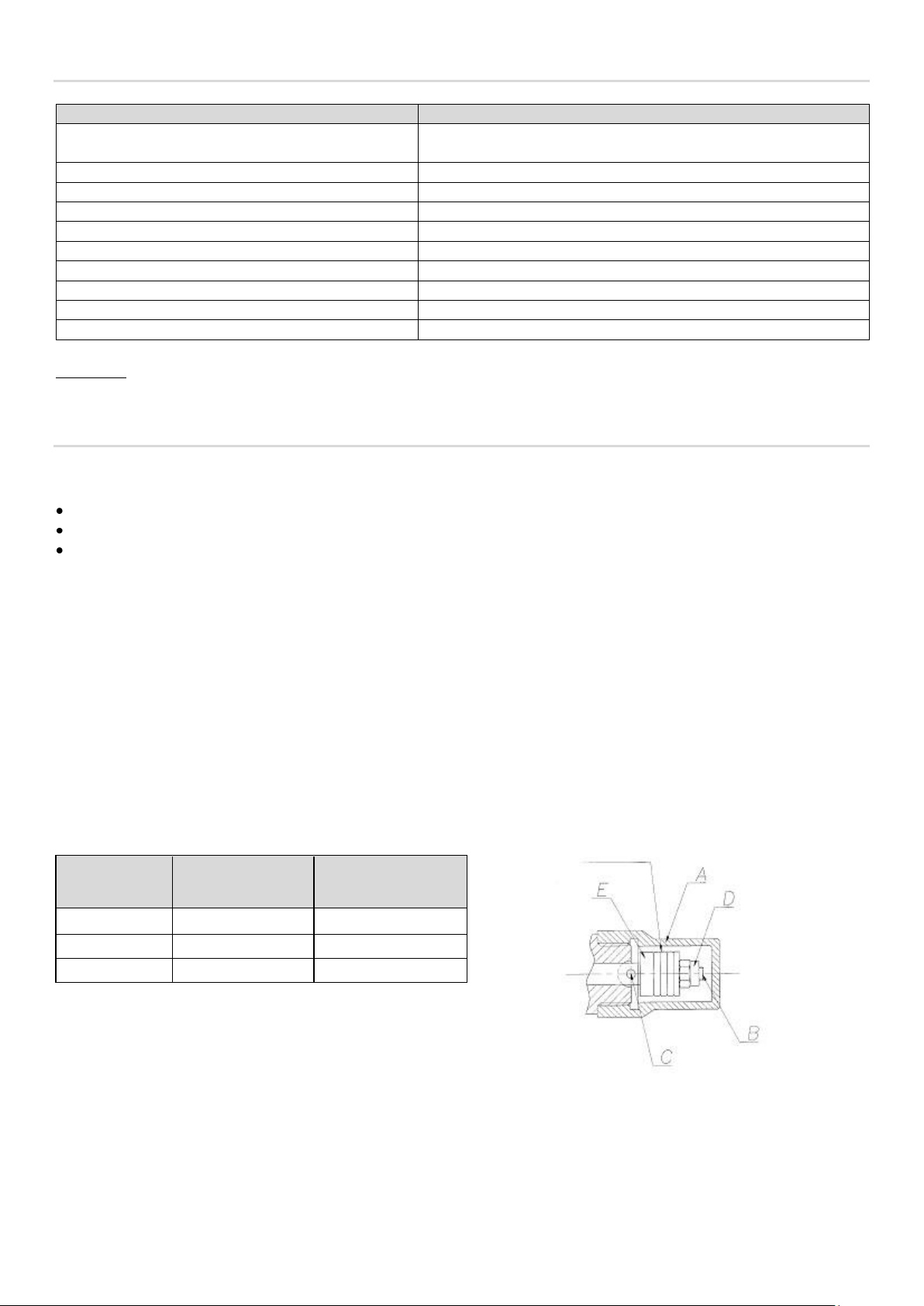
N° OF NOTCHES
FLOW RATE
(mm3/cycle)
SPACER
PART NUMBER
1
30
3233188
3
15
3233191
4 7 3233193
Notches
WARNING: DO NOT supply the machine with voltages or pressures other than those indicated on the specification plate.
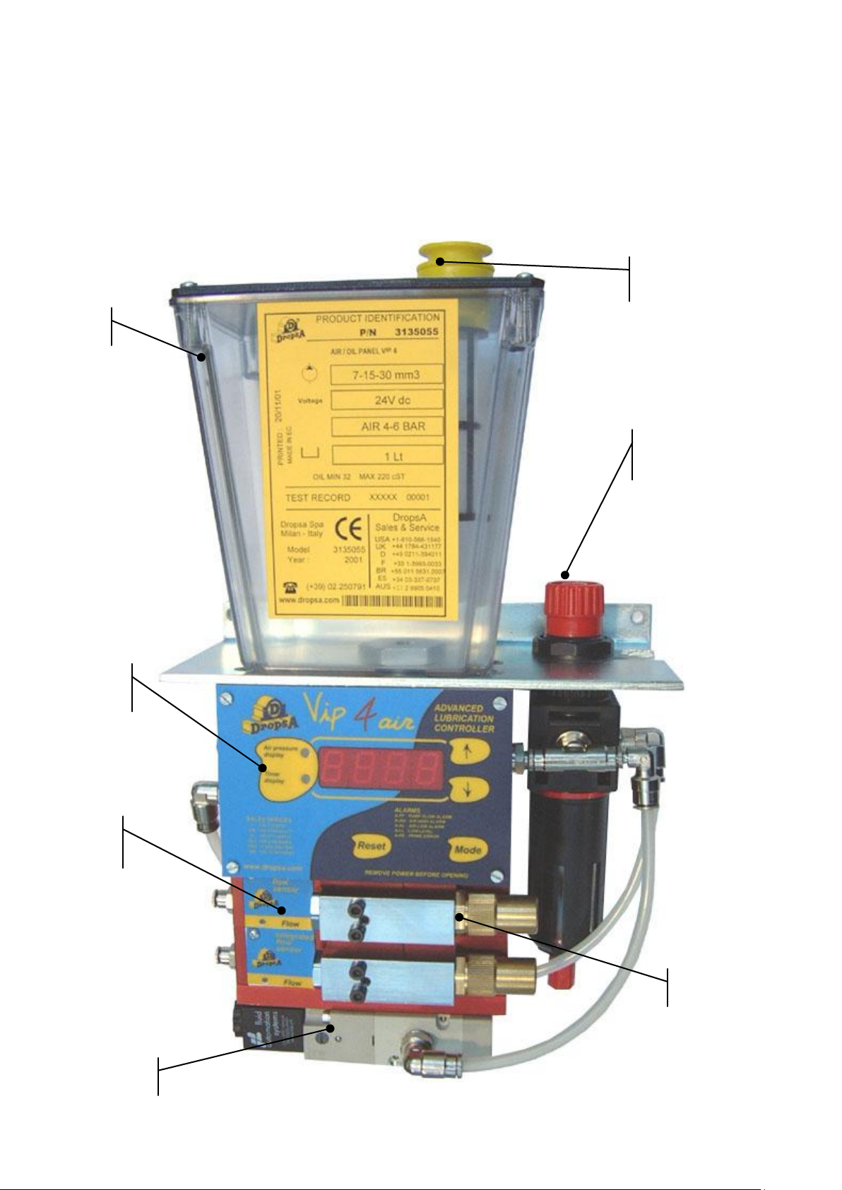
5. DESCRIPTION OF COMPONENTS
Central VIP4Air Unit
The central unit of the lubrication system is composed of the three elements:
a Tank, made of transparent plastic material, compatible with lubricants on the market.
an air control system composed of a pressure regulator, applied laterally, and a solenoid valve, which can block the air flow.
the VIP4Air panel manages and controls the entire lubrication process: the time intervals, the lubrication flow rate, the air
pressure and the oil level. In addition it provides for priming cycles (air venting).
Pneumatic Mini-pump
The mini-pumps employed are particularly small and are installed on the mixer bases. They can be fitted with a range of spacers
which serve to vary the flow rate. The following table details how to recognize these and indicates the relative part numbers. To
change the spacers proceed as follows:
1. Unscrew and remove the brass cap (A).
2. Rotate shaft (B) until the hole (C) aligns with the relative slot.
3. Insert a Ø2 mm tommy bar in hole (C).
4. Unscrew hex. nut (D) using a 5,5 mm spanner.
5. Slide off the spacer (E) and replace it with the required one.
6. Replace and fully tighten nut (D), remove the tommy bar and replace cap (A).
4
Mixer base with flow rate sensor
Oil filler
cap
Pressure
regulator
Mini-pump
Solenoid valve
Mixer base
Central
unit
Tank
In the mixer base there is an integrated lubrication detector system with a self-setting sensor. This sensor does not require to be
regulated or calibrated as it automatically adapts to the functioning conditions and the type of lubricant.
The detection system is interfaced, by means of an electrical connection completely integrated into the mixer base, with the
VIP4Air panel mounted on the central unit. Where an anomaly occurs this is detected by the central unit, which signals the
error.
The functioning is also indicated by an LED mounted on the base itself.
When the VIP4Air starts a lubrication cycle, the LED located on the mixer base illuminates (ON) until the end of the lubrication
cycle. During the pause the LED is not illuminated (OFF).
 Loading...