

DROPSA VIP4Air Series, VIP4Air 110 V AC, VIP4Air 24 V DC User And Maintenance Manual
VIP4Air
Minimal Air/Oil
Lubrication System
Automatic Lubrication Systems

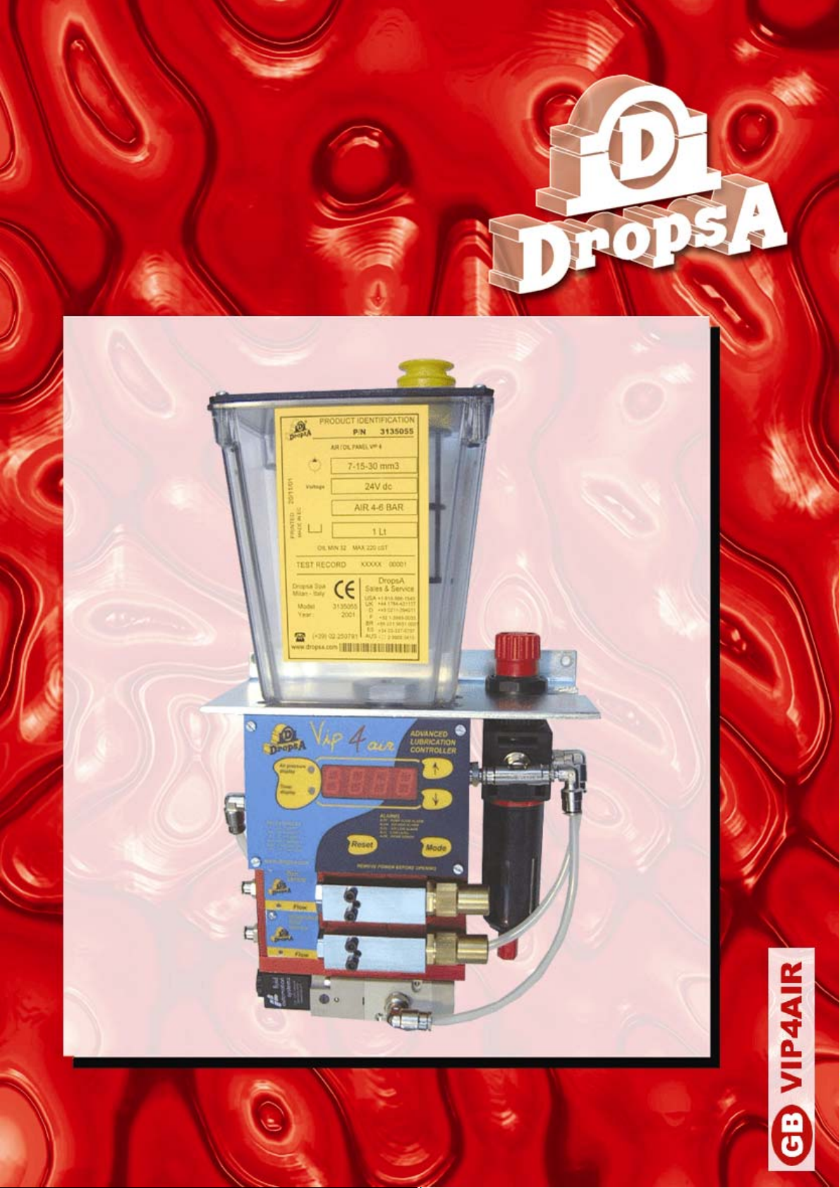
The VIP4Air is the most complete and compact
A
A
Minimal Air/Oil Lubrication System available today.
ir/Oil Minimal lubrication is a relatively new technology that has
been used successfully to substitute costly Oil Re-circulation and
non environmentally-sound Mist Systems.
It has provided excellent results both in terms of performance and
total system cost.
It is ideal for use on Bearings, High Speed Bearings, Gears and
also in certain circumstances on Guides. It is particularly suited to
Spindle Lubrication.
In the past, excessive oil has been used often only to ensure that
the ‘system is working’. This oil generates heat and has to be
collected away from the lubrication point.
Dropsa has taken the ‘minimal lubrication’ concept one step further
with the VIP4Air that can achieve ultra-low volume oil discharge
and at the same time provide electronic monitoring (using a custom
designed differential flow sensor integrated into the unit). This
allows true minimal lubrication by applying micro-amounts of
lubricants at more frequent intervals whilst giving positive feedback
that oil is correctly being injected and mixed into the air stream.
The VIP4Air System contains all components necessary to
achieve and monitor optimum minimal Air/Oil Lubrication.
PRODUCT FEATURES :
• 1 – 8 Lubrication Points each with independent monitoring
• 0.005 – 0.030 cm3 (0.0003 – 0.0018 cu.in) of oil per discharge
(standard settings 7-15-30 mm
3
)(0.0004 – 0.0009 – 0.018 cu.in).
• Tamperproof adjustment ‘rings’ avoids end-user modifications.
• Integrated Differential Flow sensor gives positive feedback of
Air/Oil lubrication.
• Fully Electronic Controls = quick Set-up and interfacing to host.
• Integrated Mixing Air Pressure Transducer provides accurate
and quick setting of Air Pressure on the electronic display, as
well as providing alarms for blocked or broken lubrication lines
via high/low air pressure monitoring.
• Automated Priming Sequence for quick and easy installation.
• Integrated & Compact – Connections are internal to the unit
Air/Oil Minimal Lubrication :
Continuous Air Flow: Cyclic micro-oil Injection:
Provides Cooling
Provides Transport Medium
Prevents Contamination and
ingress of water or dirt.
Reduces friction
Minimal quantities avoid
‘churning’ and heat generation.
No Excess Oil
Frequent lubrication intervals
help thermal stability of system.
Dropsa is a leading international manufacturer of Automatic
Lubrication Systems and can assist with a wide range of technical
and application advice, systems and components. Contact one of
our offices or distributors for more information.
N°
Pumps
VIP4Air 24 V DC VIP4Air 110 V AC
1 3135064 3135065
2 3135055 3135056
3 3135067 3135068
4 3135070 3135071
5 3135073 3135074
6 3135076 3135077
7 3135079 3135080
8 3135082 3135083
ttention: connector not included, to be ordered
separately; connector, p/n 1639115 + cable 2 mt
Technical Characteristics
VIP4Air Lubrication System
Voltage
Power
Air Pressure Inlet
Output Signal
Operating
Temperature
Humidity
Protection
Lubricants
Oil Viscosity
Reservoir capacity
Elements Y X Z Depth
24 V DC
110 V AC
10 W
5 ÷ 8 bar
(73.5 ÷ 117.6 psi)
Remote Alarm
relay: max 250 V
1 A NO / NC
-5 ÷ +55 °C
(23 ÷ 131°F)
90% max
IP-44
Mineral Oils
32 ÷ 220 cSt
(150 ÷ 1018 SUS)
1 lt
1 331
2 359
3 387
4 415
5 443
200 125
270
6 471
7 499
8 527
Web site:
http://www.dropsa.com
E-mail:
sales@dropsa.com
WK 32/03
C2033PE
ITALIA
Dropsa SpA
t.(+39) 02-250791
f.(+39) 02-25079767
ESPAÑA
Polydrop, S.A.
t.(+34) 93-260-22-50
f.(+34) 93-260-22-51
U.S.A.
Dropsa Corporation
t.(+1) 586-566-1540f.(+1) 586-566-1541
U.K.
Dropsa (UK) Ltd
t.(+44) 01784-431177
f.(+44) 01784-438598
BRAZIL
Dropsa
t.(+55) 011-563-10007
f.(+55) 011-563-19408
GERMANY
Dropsa Gmbh
t.(+49) 0211-394-011
f.(+49) 0211-394-013
AUSTRALIA
Dropsa Australia Ltd.
t.(+61) 02-9938-6644
f.(+61) 02-9938-6611
FRANCE
Dropsa Ame
t.(+33) 01-3993-0033
f.(+33) 01-3986-2636
VIP4Tools
LUBRICATION SYSTEM
User and
Maintenance Manual
Warranty Information
TABLE OF CONTENTS
1. INTRODUCTION
2. IDENTIFICATION
3. GENERAL DESCRIPTION
4. DESCRIPTION OF COMPONENTS
5. TECHNICALSPECIFICATION
6. HANDLING AND TRANSPORT
7. PRECAUTION IN USE
8. CONTRAINDICATIONS
9. INSTALLATION
10. INSTRUCTIONS FOR USE
11. MAINTENANCE
12. DISPOSAL
13. REPLACEMENT PART LIST
14. DIMENSIONS VIP 1 LITER
15. DIMENSIONS VIP 3 LITER
16. GARANTEE
17. DECLARATION OF CONFORMITY
18. DISTRIBUTORS
http://www.dropsa.com
Manufacturer
Product VIP4Tools
Year 2001
Certification
DropsA SpA
Manual drawn up in accordance with CE
Directive 98/37 Att. I, paragraph 1.7.4
C2040IE - WK 51/02

1. INTRODUCTION
This user’s and maintenance manual refers to VIP4Tools air/oil lubrication system.
This manual should be conserved in such a way that it remains undamaged over time and is readily
available to personnel needing to consult it.
Further copies of this manual, updates or clarifications can be obtained by directly contacting the
Technical Sales Office at Dropsa.
The manufacturer reserves the right to update the product and/or the user’s and maintenance manual
without the obligation to revise previous versions. It is however, possible to contact the Technical
Sales Office for the latest revision in use, or to consult our web site at http://www.dropsa.com.
The use of the equipment referred to in this manual must be entrusted to qualified personnel with a
basic knowledge of mechanics, hydraulics and electrical systems.
It is the responsibility of the installer to use tubing suitable for the system; the use of inadequate
tubing can cause problems with the pump, injury to persons and create pollution.
Loosening of connections can cause serious safety problems; carry out a check before and after
installation and, if necessary retighten them.
Never exceed the maximum working pressure values permitted for the panel and the components
connected to it.
Before any maintenance or cleaning operation disconnect the power supply, close off the air supply
and discharge the pressure from inside the equipment and the tubing connected to it.
Do not subject the panel, the connections, the tubing or parts under pressure to violent impacts;
damaged tubing or connections are dangerous and should be immediately replaced.
After long periods of inactivity check air tightness of all parts subjected to pressure.
Personnel must use personal protection equipment, clothing and tools adequate for the location and
the use of the panel both during its operation and during maintenance operations.
The panel, and any accessories mounted on it, should be carefully checked immediately on receipt
and in the event of any discrepancy or complaint the Dropsa SpA Sales department should be
contacted without delay.
Dropsa SpA declines to accept any responsibility for injuries to persons or damage to property in the
event of the non-observance of the information presented in this manual.
Any modification to component parts of the system or the different destination of use of this system or
its parts without prior written authorization from Dropsa SpA will absolve the latter from any
responsibility for injury to persons and/or damage to property and will release them from all
obligations arising from the guarantee
2. IDENTIFICATION OF THE MACHINE
A yellow plate showing the product code and the basic characteristics is mounted on the front of the
oil tank.
3. GENERAL DESCRIPTION
The VIP4Tools panel is to be utilized for ‘on mandrel’ applications, without controls on the machine,
for the lubrication of tooling and chains.
Designed for high performance at a low cost, it is distinguished by its compactness.
The system comprises a pneumatically controlled mini-pump and the mixer base. The mini-pump can
be manually regulated to cover a wide range of needs (0-30 mm³). The modular design of the system
makes it extremely versatile; up to a maximum of 8
timed by adding the pneumatic impulse generator kit P/N 3132572 or by controlling it from the
machine PLC.
mixer bases can be installed. The system can be
2
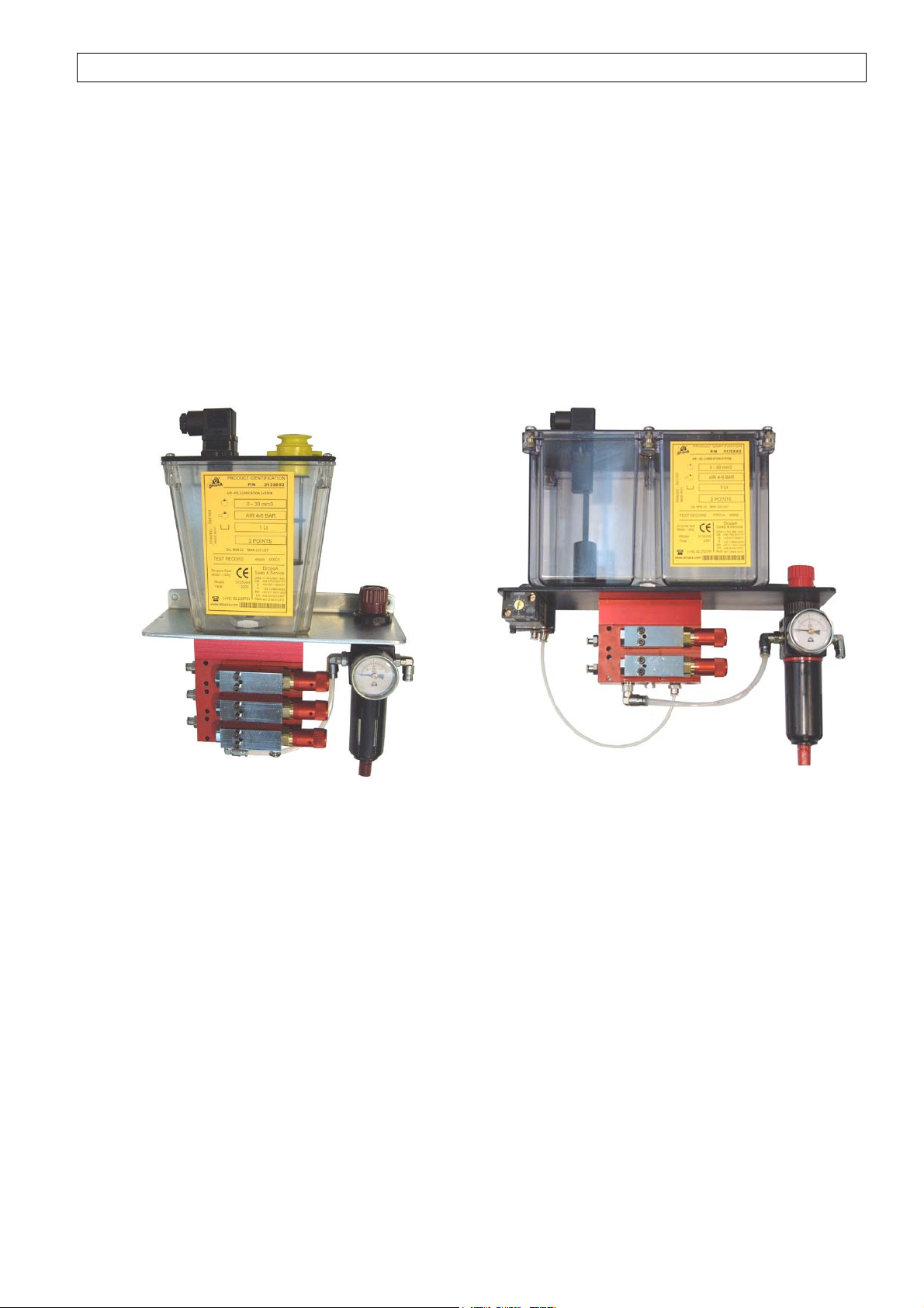
4. DESCRIPTION OF COMPONENTS
Central VIP4Tools Unit
The central unit of the lubrication system is composed of the following items:
• a Tank, made of transparent plastic material, compatible with lubricants on the market.
• a System for the regulation of the mixer air
• a modular Subframe
• a Samba type Minimum level indicator,
• an adjustable Mini-pump
1 Liter tank
3 Liter tank
ES:(version complete with timer kit)
3
 Loading...