

DROPSA MiQueL EXT, MiQueL EXT PRO - i, MiQueL EXT BASE, MiQueL EXT BASE - i, MiQueL EXT PRO User Operating And Maintenance Manual
http://www.dropsa.com
MiQueL EXT
Air/oil modular minimal system
With external pump
User Operating and
Maintenance Manual
Original text translation
Warranty Information
CONTENT
1. INTRODUCTION
2. GENERAL DESCRIPTION
3. IDENTIFICATION OF THE MACHINE
4. TECHNICAL FEATURES
5. MACHINE COMPONENTS
6. UNPACKING AND INSTALLATION
7. INSTRUCTIONS FOR USE
8. PROBLEMS AND SOLUTIONS
9. MAINTENANCE PROCEDURES
10. DISPOSAL
11. ORDER INFORMATION
12. DIMENSIONS
13. HANDLING AND TRANSPORT
14. PRECAUTIONS FOR USE
15. OPERATIONAL HAZARDS
16. WARRANTY
17. DECLARATION OF COMPLIANCE
18. DISTRIBUTORS
The manual has been prepared in compliance with Directive C2168IE – WK 01/12
EC 06/42
2
1. INTRODUCTION
Serbatoio pressurizzato
(Optional)
1
2
3
4 5 5
6
7
This user and maintenance manual relates to the MiQueL EXT.
Using this pump means that oils and greases can be distributed within lubrication systems even at high pressures of up to 400
bar (5880 psi).
The latest version may be obtained from the Technical-Commercial Office, or by consulting our web site
http://www.dropsa.com.
The pump subject of this manual must be used by qualified personnel with basic hydraulic and electrical knowledge.
This user and maintenance manual contains important information about protecting the health and safety of the personnel who
intend to use this apparatus. You must read and look after it carefully, making sure that it is available at all times for the
operators who intend to consult it.
2. GENERAL DESCRIPTION
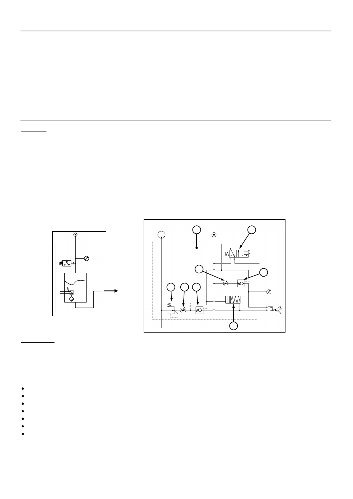
Operation
The system consists of a pressurised lubricant tank, one or more mixture regulation modules, pipes and spray nozzles (see
hydraulic diagram below).
The lubricant is sent to mixing valve through an external pump or a pressurised reservoir.
Each module has oil and air check valves that are controlled manually by the operator. The outward oil and air flow can
be managed independently between the different modules using a mini solenoid valve (“-i”version only) that activates the
control valves on the module. The module has a compensation valve (“PRO” version only) is able to keep the flow rate
constant as the inlet tank pressure and outlet counter-pressure varies.
The lubrication pipes can be traditional or coaxial. In the latter case, the lubricant and nebulisation air are transported
separately to the nozzle. The piston keeps the oil from dripping from the nozzle when the lubrication operation is complete.
Hydraulic diagram
Spray nozzles
When traditional pipes are used, the air and oil are already mixed when they arrive at the nozzle.
If coaxial pipes are used, the nozzle mixes the air and oil at the point to be lubricated. The lubricant is atomised in minuscule
particles by the air flow that passes in front of the oil outlet hole.
The geometry of the nozzle is designed based on the type of spray to be obtained (conic, blade-shaped, etc.).
Advantages
Easy to install on the machine
Reduction in tool wear
Improved surface finish on the part
No lubricant residuals left on the part when the work is complete
The nozzles do not drip after being turned off
Large spray range (up to 300 mm)
Greater safety and environmental hygiene at the workplace
3
Application
TECHNICAL SPECIFICATIONS
Pumping system
External pump
Maximum number of modules
8
Maximum Oil inlet pressure
2,5:1 in relation with air inlet pressure
Air inlet pressure
4bar ÷ 7bar [87psi ÷ 101,5psi]
Maximum air consumption at the outlet
~50Nl/min (per module)
Air inlet pipe
Ø6mm
Oil inlet pipe
Ø6mm
Air outlet pipe
Ø6mm
Oil outlet pipe
Ø3mm
Oil flow rate per element (with compensation valve)
0 ÷ 2cc/min (oil 10cSt ÷ 32 cSt)
0 ÷ 0,5cc/min (oil 32cSt ÷ 100 cSt)
Lubricant
10cSt ÷ 100cSt
Pressure switch calibration
6bar [87psi]
Element solenoid valve power supply
24Vdc
Operating temperature
+5°C ÷ +50°C
Storage temperature
-10°C ÷ +80°C
Max relative humidity without operating condensate
90%
Sound level pressure
< 70 db (A)
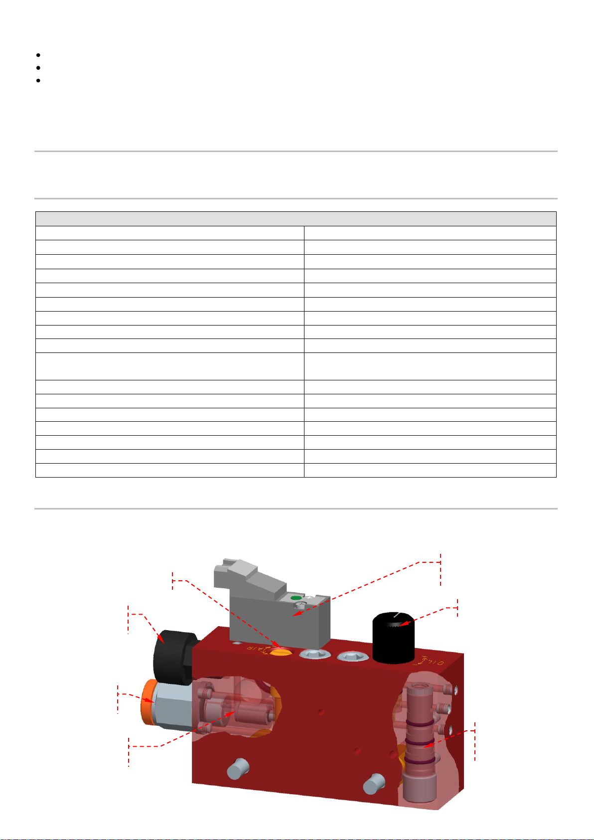
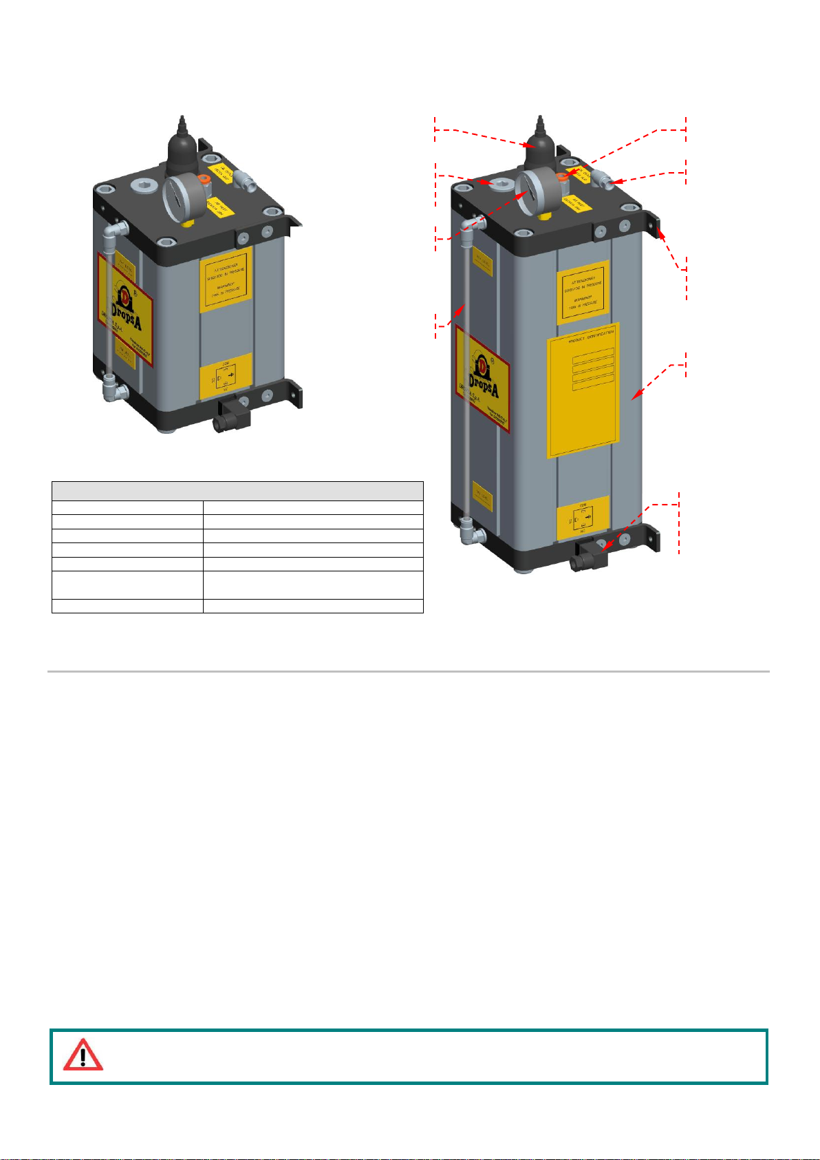
Solenoid valve
(“-i ” version only)
Pressure gauge
(optional)
Push-in pipe Ø6 air
outlet
Air regulation
Oil regulation
Compensation valve
(“PRO” version only)
Push-in pipe Ø3 oil
outlet
Machine tools
Machines for cutting and bending plate
Steelworks
The units are supplied without accessories. The installer is responsible for providing the accessories needed for safe and
correct operation (condensate separator, filters, pressure gauges, by-pass, etc…).
3. MACHINE IDENTIFICATION
There is a plate on the side of the unit that displays the product code, the power supply voltages and the basic characteristics.
4. TECHNICAL SPECIFICATIONS
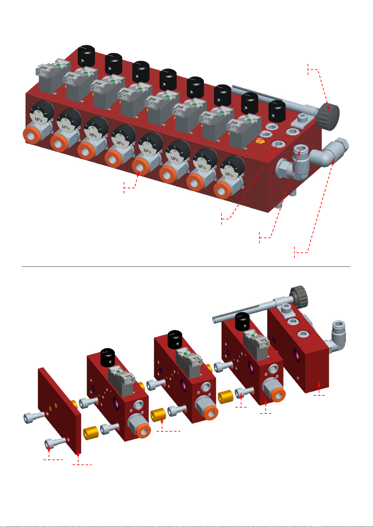
5. MACHINE COMPONENTS
MODULAR ELEMENT
4
Assembly system / increasing modular elements
Final closure
screws
Modular element
Screw assembly modules
Fixing intermidia set screw
Starting element
End cover
Modular element outlets
Air inlet
Mounting screws
Ø3 pipe removal tool
Oil inlet
MiQueL PRO-i EXT Module
5
Pressurized reservoir for MiQueL EXT (optional)
ATTENTION: Always install a regulator filter with condensate recovery on the air inlet. Any unfiltered deposits
or sediments could irreparably damage the product.
TECHNICAL SPECIFICATIONS
Reservoir capacity
1lt – 3lt
Air inlet pressure
4bar ÷ 7bar [87psi ÷ 101,5psi]
Air inlet pipe
Ø6mm
Oil outlet pipe
Ø6mm
Pressure switch calibration
6bar [87psi]
Maximum pressure switch load
Voltage free contact maximum voltage 250V
Maximum power 100W
Maximum electric level load
0,2A @ 30V
1lt Reservoir
3lt Reservoir
Pressure switch
Pressure gauge
Loading cap
Visible level
Air inlet
Oil Outlet
Mounting
brackets
Reservoir
Minimum electric
level
6
6. UNPACKING AND INSTALLATION
6.1 UNPACKING
Once the suitable location for installation has been identified, open the package and remove the unit.
Check that it was not damaged during transport or storage.
The packaging material does not require special disposal precautions as it is not in any way dangerous or polluting.
6.2 INSTALLATION
Allow a sufficient amount of space for installation, leaving a minimum perimeter space of 100 mm (3,93 in.).
Install the unit at “shoulder height” to prevent abnormal positions or the possibility of impacts.
Use the brackets with the holes (see chap. 12) to fix the unit properly. It is also possible to disassemble the brackets from their
current position and reassemble them in the prepared threaded holes for side or corner installation.
It is prohibited to use the unit if submersed in fluids or in a particularly aggressive or explosive/inflammable environment if not
previously prepared for that purpose by the supplier.
Use safety gloves or glasses as specified in the safety sheet for the lubricant.
Do not use aggressive lubricants with NBR gaskets. In the case of doubt, contact the Dropsa SpA technical office to receive a
detailed card about the recommended oils.
Do not ignore the hazards to health and comply with the health regulations.
6.3 PNEUMATIC CONNECTIONS
Before making the connection, check that the valve for the main air, the manual sliding valve and the check valves (air and oil)
are closed. Make sure that the inlet pressure does not exceed 7bar.
Use fittings and pipes that are suitable for the operating pressures, push-in connection for Ø10mm pipe.

6.4 ELECTRIC CONNECTIONS
AIR
AIR
OIL
2
1 4 3
AIR
OIL
Connect the unit to the pump or to the pressurized reservoir using suitable piping for the working pressure that must not be
greater than 2.5 times the air pressure (es.: air 6bar [87psi] – oil 15bar [217,5psi] max.).
6.5 AIR/OIL HYDRAULIC CONNECTIONS TO THE LUBRICATION NOZZLE
Using coaxial pipes, connect the Ø3mm pipe to the oil outlet push-in on the module, slide the Ø6mm tube outside the
Ø3mm tube until connect it to the air outlet push-in .
Then connect the same coaxial pipes to the lubrication nozzle push-in as shown below:
1. Insert the Ø6 air pipe in the push-in on the nozzle connection.
2. Remove the nozzle head from the articulated pipe, through which the Ø3 oil tube should pass, making it protrude approx.
20/25mm.
3. Insert the Ø3 oil pipe in the push-in on the nozzle head.
4. Replace the nozzle head on the articulated pipe.
To make it easier to remove the pipes exiting the module, use the supplied device: unscrew the Ø6 push-in, insert the device in
the Ø3 pipe, push the device on the collar of the Ø3 push-in, push and pull the Ø3 pipe.

7
7. INSTRUCTIONS FOR USE
DIAGNOSTICS TABLE
ANOMALY
CAUSE
SOLUTION
Lubrication does not take place
activating the solenoid valve.
Solenoid valve broken.
Replace the solenoid valve.
The air supply pressure is below 4 bar
[58psi].
Increase the supply pressure up to a
minimum of 4 bar.
The lubricant exits irregularly and with
large air bubbles visible in the Ø3 oil
pipe.
The Ø3 oil pipe is not perfectly engaged
into push-in of module.
Top up the tank with new lubricant.
Insert the pipe, making sure to insert it to
the end.
ATTENTION: Make sure that the pneumatic power supply is disconnected before carrying out any maintenance
work.
ATTENTION: The unit may only be opened and repaired by authorised Dropsa personnel.
Operations to perform before start-up.
Check the integrity of the unit.
Check the power supply pressure.
Check that the electric connection was carried out correctly.
Check that the unit is at the operating temperature.
7.1 USE
Open the manual cursor valve;
Press the start button on the machine to which the unit is connected or start it;
Check that the solenoid valves on the elements are correctly activated;
At the first start-up, it may be necessary to fill the oil pipes, wait until the lubricant exits;
Check that the lubrication is suitable (if there are doubts about correct operation, the Dropsa SpA technical office can be
contacted to request the inspection procedure).
7.2 REGULATION
The modular elements are normally supplied with the oil regulation and the air regulation completely closed. To regulate the
air/oil mixture for the individual elements, proceed as follows:
Turn the oil regulation knob clockwise to increase the flow rate or anticlockwise to decrease the flow rate.
Use a screwdriver to turn the air regulation pin clockwise to increase the flow rate or anticlockwise to decrease the flow rate,
until the desired spray is obtained.
8. PROBLEMS AND SOLUTIONS
A diagnostics table is provided below that indicates the main anomalies, the probable causes and the possible solutions.
If you were not able to solve the problem after consulting the diagnostics table, do not try to find the fault by disassembling
machine parts but contact the Dropsa technical office and report the discovered anomalies, with a detailed description.
9. MAINTENANCE PROCEDURES
The units were designed and built in order to minimise maintenance requirements.
To simplify maintenance, it is recommended to install them in an easy to reach position.
(See paragraph 6.2).
Periodically check the pipe joints to detect any leaks.
Always keep the modules clean to be able to quickly detect any leaks.
The machine does not require any special equipment for any control and/or maintenance activity. It is recommended to use
tools and personal protective devices suitable for use in ref. to leg. Decree 81/2008, and that are in good condition according to
current regulations to prevent damage to people or machine parts.

8
10. DISPOSAL
VERSION
DESCRIPTION
CODE
MiQueL PRO
Air/Oil modular minimal system with compensation valve
without a solenoid valve for independent control N(1-8) modules
313558N
N=1÷8 (Modules)
MiQueL PRO - i
Air/Oil modular minimal system with compensation valve
with a solenoid valve for independent control N(1-8) modules
313559N
N=1÷8 (Modules)
MiQueL BASE
Air/Oil modular minimal system without compensation valve
without a solenoid valve for independent control N(1-8) modules
313560N
N=1÷8 (Modules)
MiQueL BASE - i
Air/Oil modular minimal system without compensation valve
with a solenoid valve for independent control N(1-8) modules
313561N
N=1÷8 (Modules)
ACCESSORIES AND SPARE PARTS
CODE
DESCRIPTION
CODICE
DESCRIPTION
1525430
MiQueL PRO- i - Modular element
5717301
Ø6 AIR outlet pipe
1525440
MiQueL PRO - Modular element
3226664
Oil MK 150 20 lt.
1525450
MiQueL BASE- i - Modular element
3226665
Oil MK 100 25 lt.
1525460
MiQueL BASE - Modular element
3226666
Oil MK High Performance 29 lt.
3133561
Pressurized Reservoir for MiQueL EXT – 1lt
3225465
Oil MK Stainless 20 lt
3133560
Pressurized Reservoir for MiQueL EXT – 3lt
3133455
Coaxial nozzle - Narrow Cone Pattern
0020694
Pressure gauge for module AIR outlet (-i
3133558
65° Coaxial nozzle – flat cone
1525446
Module solenoid valve connector (-i)with 600mm cable
3133564
FULL cone monotube nozzle
1525476
Module solenoid valve connector (-i)with M8 connector
3133565
65° monotube nozzle flat cone
1525442
Module solenoid valve (-i)
1525050
Monotube nozzle for 50mm BLADE
5717232
Outlet oil Ø3 tube
1525051
Monotube nozzle for 70mm BLADE
During machine maintenance, or if it is demolished, do not dispose of the polluting parts in an improper manner. Refer to the
local regulations for their correct disposal. When demolishing the machine, the identification plate and all other documents
must be destroyed.
11. ORDER INFORMATION
11.1 ACCESSORIES AND SPARE PARTS
For more information about accessories and spare parts, contact our technical sales office.

9
12. DIMENSIONS
MiQueL - EXT
Reservoir for MiQueL EXT (optional)
Dimensions in mm [inch].

10
13. HANDLING AND TRANSPORT
Note: Personnel must use protective devices, garments and tools in compliance with current standards with
regard to the location and the use of the unit both during work as well as during maintenance operations.
Lift the equipment according to the direction shown on the cardboard package.
The machine components can be stored at temperatures between -30 and + 80 °C; however, to prevent
damage, it must only be started up after the machine has reached a temperature of +5 °C.
ATTENTION!
Never try to stop or deviate any leaks with your hands or other body parts.
Before shipping, the units are carefully packed inside cardboard boxes. When transporting and storing the equipment, pay
attention to the direction indicated on the boxes themselves.
Upon receipt, check that the package has not been damaged and store the equipment in a dry location.
14. PRECAUTIONS FOR USE
The warnings about the risks involved in using a unit for lubricants must be read.
The operator must understand its operation and clearly understand the hazards connected to pumping pressurised oils.
Therefore we recommend the following:
Check the chemical compatibility of the material with which the unit is built with the fluid to be pumped (see chap. 4). An
incorrect selection could cause, in addition to damaging the units and pipes, serious risks for people (spillage of irritating
products that are harmful to health) and for the environment.
Never exceed the maximum operating pressure permitted for the unit and the components connected to it. In the case of
doubt, refer to the data specified on the machine plate.
Only use original spare parts.
If components must be replaced with others, make sure they are suitable for operating at the unit's maximum operating
pressure.
Electric current
Do not carry out any work on the machine before disconnecting it from the electrical power supply and making sure that no one
can reconnect it during the operation. All the installed equipment (electric and electronic), tanks and basic structures must be
connected to the ground line.
Inflammability
The lubricant used in the lubrication circuits is normally not an inflammable liquid. It is however necessary to adopt all the
possible measures to prevent that it comes into contact with very hot parts or open flames.
Pressure
Before each operation, make sure there in every branch of the lubrication circuit that there is no residual pressure that could
cause oil to spray when disassembling fittings or components.
After long periods of inactivity, check the seal of all the parts subject to pressure.
Do not subject the fittings, pipes and pressurised parts to violent impacts.
Damaged flexible pipes or fittings are DANGEROUS and must be replaced.
Only original spare parts should be used.
Noise
Under normal operating conditions, noise emission does not exceed 70 dB “A” at a distance of 1 metre (39.3 inches) from the
unit.
For further information about the technical specifications and the safety measures to adopt, refer to the product safety sheet
(Directive 93/112/EEC) relative to the type of lubricant selected and supplied by the manufacturer.

11
15. GUIDELINES FOR USE
FLUIDS THAT ARE NOT PERMITTED
FLUIDS
RISKS
Lubricants with abrasive additives.
Wear of internal components.
Lubricants with silicone additives.
Seizure.
Petrol – solvents – inflammable liquids.
Fire – explosion – damage to the gaskets.
Corrosive products.
Corrosion - damage to people.
Water.
Unit oxidation.
Food substances.
They would be contaminated.
Compliance with the essential safety requirements and the provisions specified in the machine directive was checked by filling
out prepared check lists that are contained in the technical file.
Two types of lists were used:
Risk assessment (UNI EN ISO 14121-1).
Compliance with the essential safety requirements Machine Directive –EC 06/42).
The risks that were not completely eliminated, but considered acceptable, are specified below:
During maintenance, sprays of oil at low pressure are possible (for this purpose, suitable PPE must be worn during
maintenance activities).
Unsuitable postures: The correct dimensions and installation methods are described in this manual.
Use of unsuitable lubricant: The specifications of the lubricant are indicated both on the unit as well as in this User and
maintenance manual (in the case of doubt, contact the Dropsa S.p.A technical office).

12
16. WARRANTY INFORMATION
All products manufactured and marketed by Dropsa are warranted to be free of defects in material or workmanship for a period
of at least 12 months from date of delivery. Extended warranty coverage applies as follows:
Complete system installation by Dropsa: 24 Months
All other components: 12 months from date of installation; if installed 6 months or more after ship date, warranty shall be
maximum of 18 months from ship date.
If a fault develops, notify us giving a complete description of the alleged:
malfunction
part number(s)
test record number where available (format xxxxxx-xxxxxx)
date of delivery
date of installation
operating conditions of subject product(s)
We will subsequently review this information and, at our option, supply you with either servicing data or shipping instruction
and returned materials authorization (RMA) which will have instructions on how to prepare the product for return.
Upon prepaid receipt of subject product to an authorized Dropsa Sales & Service location, we will then either repair or replace
such product(s), at out option, and if determined to be a warranted defect, we will perform such necessary product repairs or
replace such product(s) at our expense.
Dropsa S.p.A. reserves to right to charge an administration fee if the product(s) returned are found to be not defective.
This limited warranty does not cover any products, damages or injuries resulting from misuse, neglect, normal expected wear,
chemically caused corrosion, improper installation or operation contrary to factory recommendation. Nor does it cover
equipment that has been modified, tampered with or altered without authorization.
Consumables and perishable products are excluded from this or any other warranty.
No other extended liabilities are states or implied and this warranty in no event covers incidental or consequential damages,
injuries or costs resulting from any such defective product(s).
The use of Dropsa product(s) implies the acceptance of our warranty conditions. Modifications to our standard warranty must
be in made in writing and approved by Dropsa S.p.A.

13
Dropsa Spa
Via Benedetto Croce, 1
20090 Vimodrone (MI)
Italy
Tel.:
Fax Sales:
E-mail:
Web site:
(+39) 02. 250.79.1
(+39) 02. 250.79.767
sales@dropsa.it
http://www.dropsa.com
DICHIARAZIONE DI CONFORMITÁ/DECLARATION OF COMPLIANCE WITH STANDARDS/
DECLARATION DE CONFORMITE/ KONFORMITÄTSERKLÄRUNG DES STANDARDS /DECLARACIÓN DE
CONFORMIDAD/ DECLARAÇÃO DE CONFORMIDADE
La società Dropsa S.p.A., con sede legale in Milano, Via Besana,5/ Dropsa S.p.A., registered office in Milan, Via
Besana,5 / Dropsa S.p.A. au Siège Social à Milan, Via Besana,5/ Dropsa S.p.A., Sitz in Milano, Via Besana 5/ La
sociedad Dropsa S.p.a., con sede legal en Milán, Via Besana,5/ A Dropsa S.p.A, com sede em Milão, via Besana, nº 5
DICHIARA /CERTIFIES / CERTIFIE/ ZERTIFIZIERT, DASS/ DECLARA/ CERTIFICA:
che il prodotto denominato/that the product called/ le produit appelè/ das Produkt mit dem Namen/ el producto que se
llama/ o produto chamado:
Descrizione/ Description/ Description/ Beschreibung/
Descripción/ Descrição:
Lubrificatore Modulare Aria/Olio
Air/Oil Modular Lubricator
Nome Commerciale/ Product Name/ Dénomination/
Handelsname/ Denominación/ Denominação:
MiQueL EXT
Versioni/ Versions/ Versions/ Versionen/ Versiones/
Versões:
EXT -PRO/ EXT -PRO I / EXT-BASE/ EXT-
BASE I
Codici/ Codes/ Códigos/:
3135581÷3135618
è conforme alle condizioni previste dalle Direttive CEE /has been constructed in conformity with the Directives Of
The Council Of The European Community on the standardization of the legislations of member states/ a été
construite en conformité avec les Directives Du Conseil Des Communautes Europeennes/ Entsprechend den
Richtlinien des Rates Der Europäischen Union, für die Standarisierung der Legislative der Mitgliederstaaten,
konstruiert wurde/ cumple con las condiciones establecidas por las directivas comunitarias/ foi construído em
conformidade com as diretivas do Conselho das Comunidades Europeias:
2006/95 CE Bassa tensione / Low Voltage Directive / Directive Basse Tension/ Niedrigspannungsrichtlinien/ Directiva de
baja tensión/ Directiva de Baixa Tensão;
2004/108 CE Compatibilità elettromagnetica/ Electromagnetic Compatibility/ Compatibilité electromagnétique/
Elektromagnetische Verträglichkeit/ Compatibilidad electromagnetica / Compatibilidade Eletromagnética
17. DECLARATION OF CONFORMITY
Technical Director:
Maurizio Greco
.....................................
Legal representative
Milena Gavazzi
.....................................
Vimodrone (MI), Gennaio 2012
La persona autorizzata a costituire il Fascicolo Tecnico c/presso Dropsa S.P.A.
The person authorized to compile the Technical File care of Dropsa S.P.A.

14
18. DISTRIBUTORS
Dropsa S.p.A.
Via B. Croce,1
20090 Vimodrone (MI) Italy.
Tel: (+39) 02 - 250.79.1
Fax: (+39) 02 - 250.79.767
E-mail: sales@dropsa.it (Export)
E-mail: vendite@dropsa.it (National)
Dropsa Ame
23, Av.des.Morillons
Z.I. des Doucettes 91140
Garges Les Gonesse, France
Tel: (+33) 01 39 93 00 33
Fax: (+33) 01 39 86 26 36
E-mail: salesfr@dropsa.com
Dropsa (UK) Ltd
Unit 6, Egham Business Village,
Egham,Surrey,TW20 8RB
Tel: (+44) 01784 - 431177
Fax: (+44) 01784 - 438598
E-mail: salesuk@dropsa.com
Dropsa do Brazil Ind. E Com. Ltda
Rua Sobralia 175,
Sao Paulo, Brazil
Tel: (+55) 011-5631-0007
Fax: (+55) 011-5631-9408
E-mail: salesbr@dropsa.com
Dropsa USA Inc.
6645 Burroughs Ave
48314-2132 Srerling Hts,Mi Us -USA
Tel: (+1) 586-566-1540
Fax: (+1) 586-566-1541
E-mail: salesusa@dropsa.com
Dropsa Lubrication Systems
Nr 8 Dongxing Road,
Songjiang Industrial Zone
(Shanghai) Co., Ltd
Tel: +86 (021) 67740275
Fax: +86 (021) 67740205
E-mail: china@dropsa.com
Dropsa Gmbh
Volmerswerther Strasse 80
40221 Dusseldorf 1, Deutschland
Tel: (+49) 0211/39 4011
Fax:(+49) 0211/39 4013
E-mail: sales@dropsa.de
Dropsa Australia Pty.
C20/148 Old Pittwater Road
Brookvale, NSW 2100
Tel: +61 (02) 9938 6644
Fax: +61 (02) 99 386 611
E-mail: salesau@dropsa.com
Web site: http://www.dropsa.com - E-mail: sales@dropsa.com
 Loading...