

DROPSA Mini-SUMO User And Maintenance Manual
Mini-SUMO Pump
Manuale redatto in conformità alla Direttiva C2197IE– WK 13/12
CE 06/42
http://www.dropsa.com
CONTENTS
1. INTRODUCTION
2. GENERAL DESCRIPTION
3. TECHNICAL CHARACTERISTICS
4. PUMP COMPONENTS AND TECHNICAL CONNECTIONS
5. UNPACKING AND INSTALLATION
6. INSTRUCTIONS FOR USE
7. PROBLEMS AND SOLUTIONS
8. MAINTENANCE PROCEDURES
9. DISPOSAL
10. INFORMATION ABOUT ORDERING
11. DIMENSIONS
12. HANDLING AND TRANSPORT
13. PRECAUTIONS FOR USE
14. CLEANING
15. TRAINING
16. WARRANTY
17. DECLARATION OF INCORPORATION
18. DISTRIBUTORS
Version in compliance with Directive CE 94/9 (ATEX)
User and Maintenance Manual
Original text translation
Guarantee
II 2GD ck IIC+H2 T100 °C IP65

1. INTRODUCTION
This user and maintenance manual relates to the Mini-SUMO Atex Pump, version in compliance with ATEX standards, for
potentially hazardous areas, classified zones 1 and 21 with presence of IIC+H2 group inflammable gas and combustible dusts.
The maximum surface temperature developed by Mini-SUMO Atex pump in the most extreme conditions is 100°C.
The Mini-SUMO Atex Pump allows grease to be distributed within lubrication systems at high pressures of up to 400 bar (5880
psi).
The latest version may be obtained from Dropsa Sales Office, or by consulting our web site http://www.dropsa.com.
This user and maintenance manual contains important information about protecting the health and safety. You must read and
look after it carefully, making sure that it is available at all times for any operators that may need to consult it.
2. GENERAL DESCRIPTION
The Mini-SUMO Atex lubrication pump series is particularly suited for dual line systems and progressive systems and can be
adapted to many needs without making mechanical changes, even after installation is complete. In fact, by selecting from a set
of components that are perfectly compatible with each other and easily assembled, it is possible to vary the pressure, the
quantity of the delivered lubricant, the type of lubricant and the type of distribution. This Pump consists of the following:
Electric motor;
Pump body manifold with integrated pressure adjustment (bypass) and instrumentation;
Two pumping elements;
Reservoir;
Dual Line Pressure change-over valve.
There is one load bearing structure for all versions, the dual pumping element constitutes the essential module.
The pump unit has only one outlet.
Two types of grease tanks and two for oil, with different volumes (10 or 30 kg) can be positioned on the pump casing, with
spatula and level indicators.
The electric Mini-SUMO Atex pump is fully protected against the external environment and can run without problems in the
most severe ambient conditions.
2

3. IDENTIFICATION OF THE MACHINE AND MARKING
Figure 3.1
On the front part of the pump tank there is a plate which indicates the product code, the supply voltage and basic
characteristics.
On the pallet, a reference plate indicates the ATEX marking and certification (Figure 3.1)
3.1 ATEX Information
II Group of equipment for surface (not for mines or underground)
2GD equipment for explosive atmosphere due to flammable gas and combustible dust. 2GD Category is
appropriate for zones classified as 1 zone (2 zone included) and 21 zone (22 zone included).
c Protection mode designed for the method of construction (EN 13463-5 normative).
k Protection mode designed by oil immersion (EN 13463-8 normative).
IIC+H2 Group of flammable gas allowed IIB with hydrogen (IIA group gas included).
T5 Max. surface temperature for flammable gas.
T 100 °C Max. surface temperature for combustible dust
IP65 Protection grade (view note).
Note: IP65 protection grade is referred to electric parts. Not electric parts are protected from combustible dust by the type of
process that provides for the continued presence of oil and grease on the mechanical ignition sources.
WARNING: do not supply the machine with voltages and pressures different from those indicated on the plate.
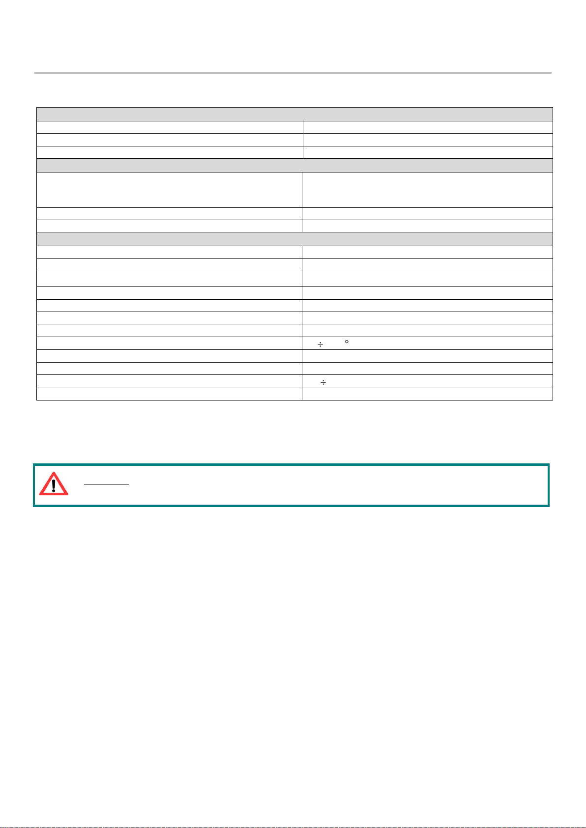
GENERAL CHARACTERISTICS
Empty weight (10 Kg tank)
62 Kg
Empty weight (30 Kg tank)
65 Kg
Empty weight pump without reservoir
42 Kg
ELECTRICAL CHARACTERISTICS
Motor power supply
3 Ph - 0,25 Kw - 230Δ/400Y 50/60 Hz – Maximum working
voltage 690V.
Motor degree of protection
IP 65
Minimum and maximum level
Capacitive-laser-ultrasounds
HYDRAULIC CHARACTERISTICS
Pumping system
Piston
Flow rate (per pumping element)
25 cc/min
Maximum operating pressures
380 bar
Outlet connection
G3/8” BSP
Tank capacity
10-30 Kg
Loading filter
Degree of filtering 300 µ
By-pass
Adjustable 0÷380 bar – precalibrated 300 bar
Temperature of use
- 5 + 50 C
Operating humidity
90 % rel. humidity
Permitted lubricants
(1)
Mineral lubricating oil min 32 cSt; grease max NLGI2
Storage temperature
-20 +65 °C
Continuous sound pressure level
< 70 dB (A)
4. TECHNICAL CHARACTERISTICS
The pump consists of a series of components with the following characteristics:
N.b. The specifications refer to the temperature of use of +20°C (+68°F)
(1)
If a different product is used, please contact Dropsa S.p.A. to ensure it is suitable for use.
4
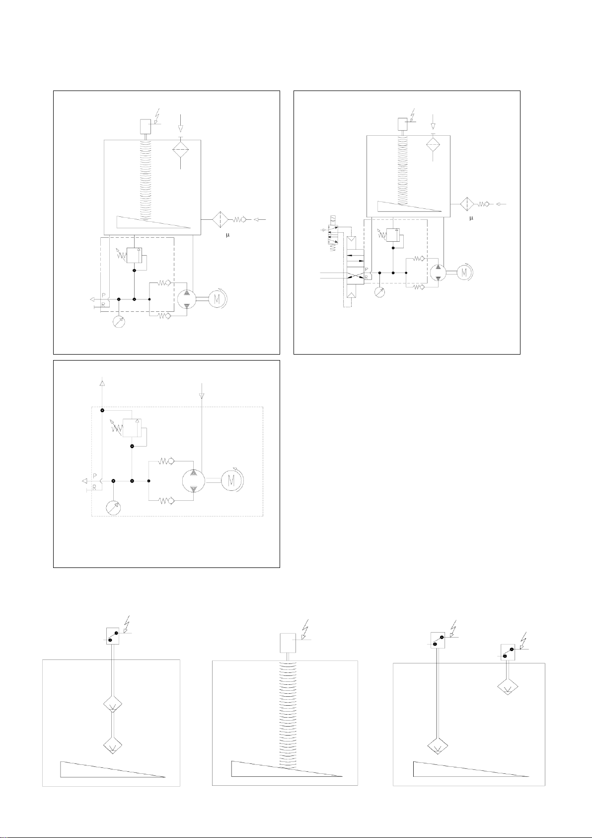
4.1 HYDRAULIC FUNCTION DIAGRAM
Hydraulic diagram for standard pump
with single grease outlet
0.18 kw – 4p
G3/8”
BSP
Hydraulic diagram for grease pump with
Electropneumatic switch – Dual line
Line 1
Line 2
0-600 BAR
0-380 BAR
0.67 cc/stroke
Pmax 380 BAR
300
Electropneumatic
switch
G½” BSP Lubricant
loading (Grease
version)
Lubricant loading
(Oil version)
0-600 BAR
0.18 kw – 4p
0-380 BAR
Hydraulic diagram for oil pump without reservoir –
single line
Linea 1
Linea 2
0.67 cc/giro
Pmax 380 BAR
G3/8”
BSP
0-380 BAR
Line 1
Line 2
0-600 BAR
0.67 cc/stroke
Pmax 380 BAR
0.18 kw – 4p
300
G½” BSP Lubricant
loading (Grease version)
G3/8”
BSP
Lubricant loading
(Oil version)
Minimum and
maxinmum floating level
Minimum and maxinmum
laser level
Minimum level capacitance
Microswitch maxinmum level
The hydraulic diagrams related to the different configurations that can be obtained using the available accessories are shown
below (see paragraph 11)
4.1.1 LEVELS AVAILABLE
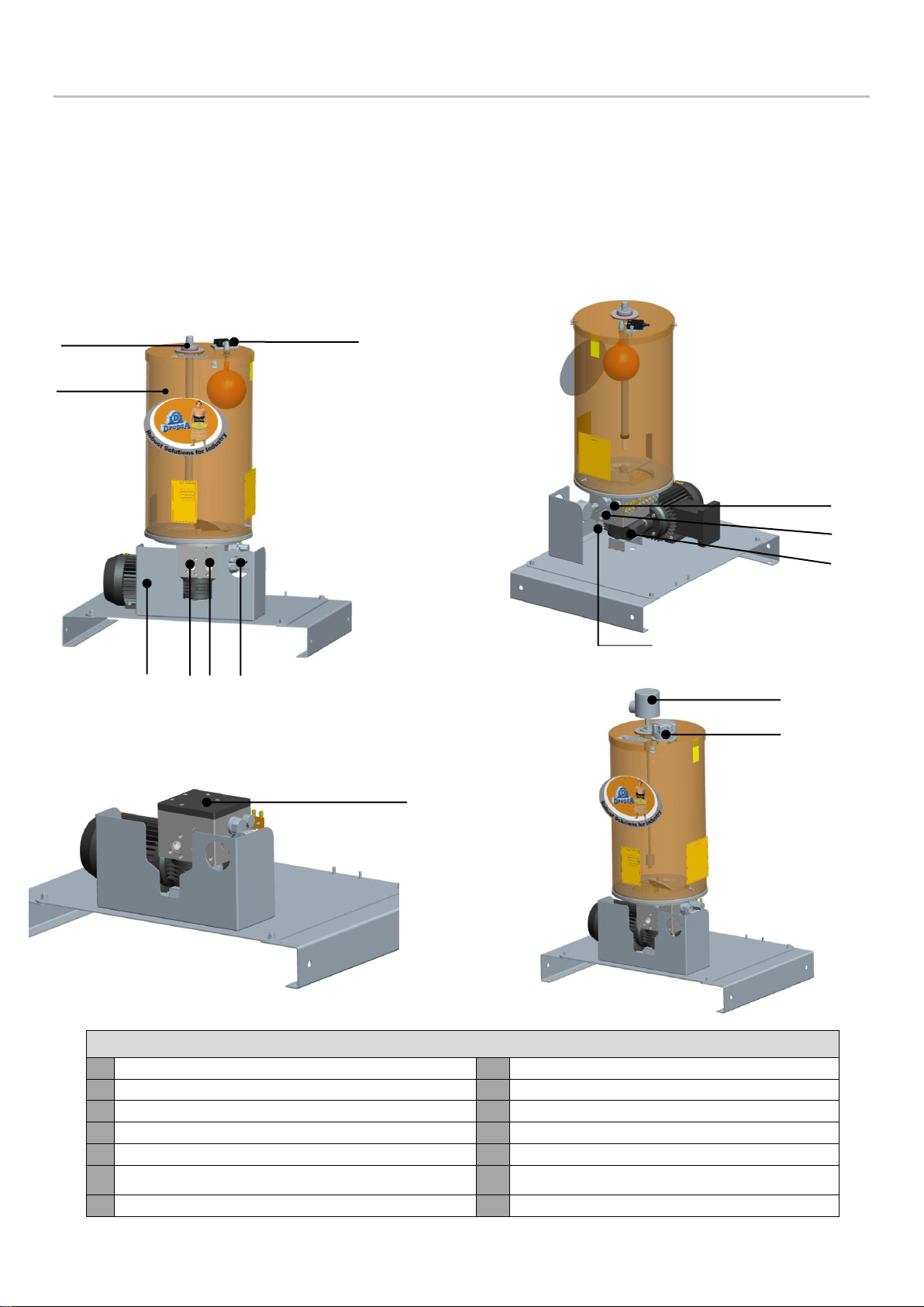
STANDARD PUMP COMPONENTS
1
Minimum capacitive level for grease pump
8
Pumping system
2
Microswitch Maximum level for grease pump
9
Pressure gauge
3
Reservoir
10
Loading (for grease pump with reservoir)
4
Ratio motor
11
Loading (for oil pump with reservoir)
5
Return
12
Minimum and maximum level indicators for oil
6
Delivery
13
Protection carter
7
By-pass
8
10
7
11
11
12
2
3
5
6
1
13
9
4
5. PUMP COMPONENTS AND ELECTRICAL CONNECTIONS
5.1 PUMPING ELEMENTS
The pump has two fixed delivery standard pumping elements (25 cm^3/ min for each pumping element).
The seal between the piston and the pumping body is of a dry type, with no gasket provided between the two.
The pumping element retention valve is of the tapered seal type. This solution is able to guarantee an optimum seal for the
system at high operating pressures (max. pressure of 380 bar).
The pumping elements are assembled onto the pump body without disconnecting the hydraulic line thanks to a threaded
cartridge design, facilitating assembly/disassembling.
Figure a – Version with reservoir
Figure b – Version without reservoir
6

5.2 MINIMUM AND MAXIMUM GREASE LEVEL INDICATORS
The standard grease pumps have two level types:
Minimum capacitive level (for 10 and 30 Kg tanks);
Max visible level (floating).
You can install a laser level type as alternative.
Minimum and maximum level are floating switch type in oil version.
5.2.1 MINIMUM CAPACITIVE LEVEL (GREASE)
The minimum level is realised by a capacitive probe that is positioned at the end of a tube mounted on the tank cover. When the
minimum level is reached, the probe signals that the lubricant is low. If the capacitive probe is replaced, the capacitive probe
must be recalibrated (see calibration procedure – CHAP. 7.2. User instructions).
5.2.2 MAX LEVEL WITH MICRO-SWITCH (GREASE)
The phase that the lubricant is loaded in the tank is realised by the operator, who uses a pump.
Once the maximum lubricant level is reached, a rod is activated that indicates that the tank is full.
5.2.3 LASER-LEVEL (OIL AND GREASE)
Inside the Ex d kit case there is a laser range sensor with connector.
It has a 4-digit alphanumeric display and a reading distance up to 10 Mt.
The device includes the programming buttons.
5.2.4 MINIMUM AND MAXIMUM LEVEL WITH A FLOAT (OIL)
The level is made with two floats at the ends of metal shaft. Lower float acts as a minimum level by closing a contact when the
low position is reached. The Upper floats acts as a maximum level by closing another contact at high position.
5.3 SPATULA FOR GREASE
Two tanks have been foreseen with capacities of 10 and 30 kg. (22 – 66.1 Lb) two for oil and two for grease.
The tanks are supplied standard with a spatula and a scraper, which must not be disassembled during their assembly or
replacement. Under the spatula, there is a standard electrogalvanised steel mesh with 0.5 mm holes (0.02 in.). The pump is
protected from possible foreign bodies that could be inadvertently present while the tank is being loaded.
5.4 PRESSURE GAUGE
The pressure gauge is glycerine type, so as protect it from any pressure spikes that may create damage. It is assembled directly
in the manifold group (placed in front of the pump).
5.5 BY-PASS
Pressure gauge is pre-calibrated to 300 bar but it can be adjustable from 0 to 380 bar.
5.6 ELECTRICAL CONNECTIONS
On the structure of the base is possible to mount a safety terminal box that contains a terminal board to connect the electrical
components of the Mini-SUMO Atex assembly (Motor, valves, level indicators, etc).
Choosing this option the pump will be supplied with wirings already connected to the terminal strip.
 Loading...