

DROPSA Dragon Series User And Maintenance Manual
PUMP SERIES
DRAGON
User and
Maintenance Manual
Warranty information
1. INTRODUCTION
2. GENERAL DESCRIPTION
3. PRODUCT-MACHINE IDENTIFICATION
4. TECHNICAL SPECIFICATIONS
5. MACHINE COMPONENTS
6. UNPACKING AND INSTALLING THE MACHINE
7. INSTRUCTIONS FOR USE
8. TROUBLESHOOTING
9. MAINTENANCE PROCEDURE
10. DISPOSAL
11. ORDERING INFORMATION
12. DIMENSIONS
13. HANDLING AND TRANSPORTATION
14. OPERATING HAZARDS
15. PRECAUTIONS
16. WARRANTY INFORMATION
17. DECLARATION OF COMPLIANCE WITH STANDARDS
18. DROPSA LOCATIONS
Manual drawn up in accordance with C2000IE– WK 17/11
EC Directive 06/42
TABLE OF CONTENTS
http://www.dropsa.com

2
1. INTRODUCTION
This manual provides instructions for the use and maintenance of the Dragone pump, which is designed for use in
lubrication systems using mineral oil or fluid grease.
The manual should be kept in a safe place in which it is protected from damage and does not deteriorate over time; it
should be easily available to any staff member who wishes to consult it.
For other copies of the manual, updates or clarifications, please contact the technical office of Dropsa SpA.
The Dragone pump may only be operated by qualified personnel who have basic hydraulic and electrical skills.
The manufacturer reserves the right to update the product and/or manual without necessarily revising the preceding
versions. It is however possible to request the latest version in use from the Dropsa SpA technical office.
The overall condition of the pump, and of any accessories attached to it, should be checked immediately after
receiving it. In the event of a complaint, immediately contact the commercial office of Dropsa SpA.
DROPSA S.p.A. is absolved from any responsibility for damage to persons or things in the event that the instructions
outlined in this manual are not followed.
Any modifications to the components of the system or any usage of the system (and its parts) differing from its
intended use without written permission from DROPSA S.p.A. will absolve the company from any responsibility for
damage to persons and/or things and will also absolve the company from any guarantee obligations.
The importer and the instructions for ordering the model desired are reported in Chapter 4.
2. GENERAL DESCRIPTION
This series of pumps is particularly suited for feeding lubrication systems. There are three basic versions:
motor-driven gear pumps:
For lubrication systems with injectors and for circulation systems with operating pressure < 20 bar (290 psi) –
system 01
With a built-in release valve, for lubrication systems equipped with “direct response” feeding devices with
operating pressure < 50 bar (750 psi) – system 33V
For progressive lubrication systems and for circulation systems controlled by progressive feeding devices
with operating pressure < 70 bar (1015 psi) – system 26
Pressure maximum:
with intermittent running is 70 bar (1015 psi) with a three-phase motor, 40 bar (580 psi) with a single-phase
motor
with continuous running is 30 bar (435 psi) with single-phase or three-phase motor.
The operating temperature is + 5 C + 40 C.
The system may only be used with mineral lubricating oil that has a viscosity of 15 1000 cSt or NGLI 000 grease (at
operating temperature); in the event that a different product is to be used, authorisation must first be received from
Dropsa S.p.A.
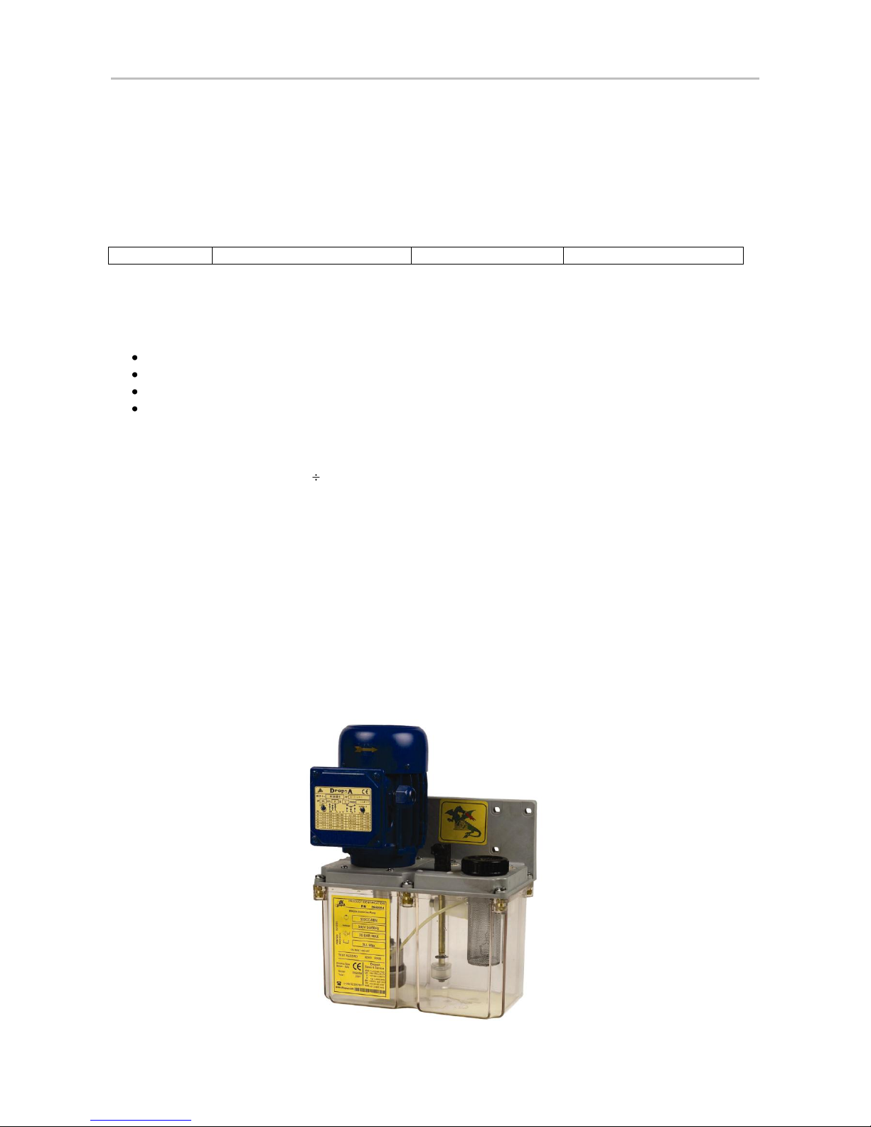
3. PRODUCT-MACHINE IDENTIFICATION
Machine identification yellow label is located on the front side of the reservoir and contains product serial number,
input voltage and details of the operating parameters.
3
4. TECHNICAL SPECIFICATIONS
4.1 Hydraulic system
Connection between the gear pump and the valve body by means of nylon tubing, external 4 mm.
4.2 Electric system
All the electrical components must be grounded. This applies both to the electrical components themselves and the
control devices. To this end, ensure that the grounding wire is correctly connected. For safety reasons, the grounding
conductor must be approx. 100 mm longer than the phase conductors. In the event of an accidental disconnection of
the cable, the grounding terminal must be the last to detach itself.
In order to avoid the danger of fulguration due to direct or indirect contacts with the live parts, it is necessary that the
electric power supply line be adequately protected by a special magnetothermal differential switch with a cut-off
threshold of 0.03 Ampere and a maximum cut-off time of 1 second.
The cut-off power of the switch must be 10 kA and the rated current In = 4 A.
TECHNICAL CHARACTERISTICS
Operating Voltage
220 Vac 50 Hz
220 440 Vac 50 - 60 Hz
Power absorption
90 W
Output Signal
Contact minimum level: 220V 3A NO/NC
Working Temperature
+ 5 + 60 C
Working Humidity
90 %
Mechanical Protection Grade
IP 55
Lubricant Viscosity
Mineral Oil 15-1000 cSt
Storage Temperature
-20 +65 °C
Sound Pressure Level
< 70 dB(A)
NOTE: At the end of all connecting operations, make sure that pipes and wires are safe from
impacts and carefully fixed.
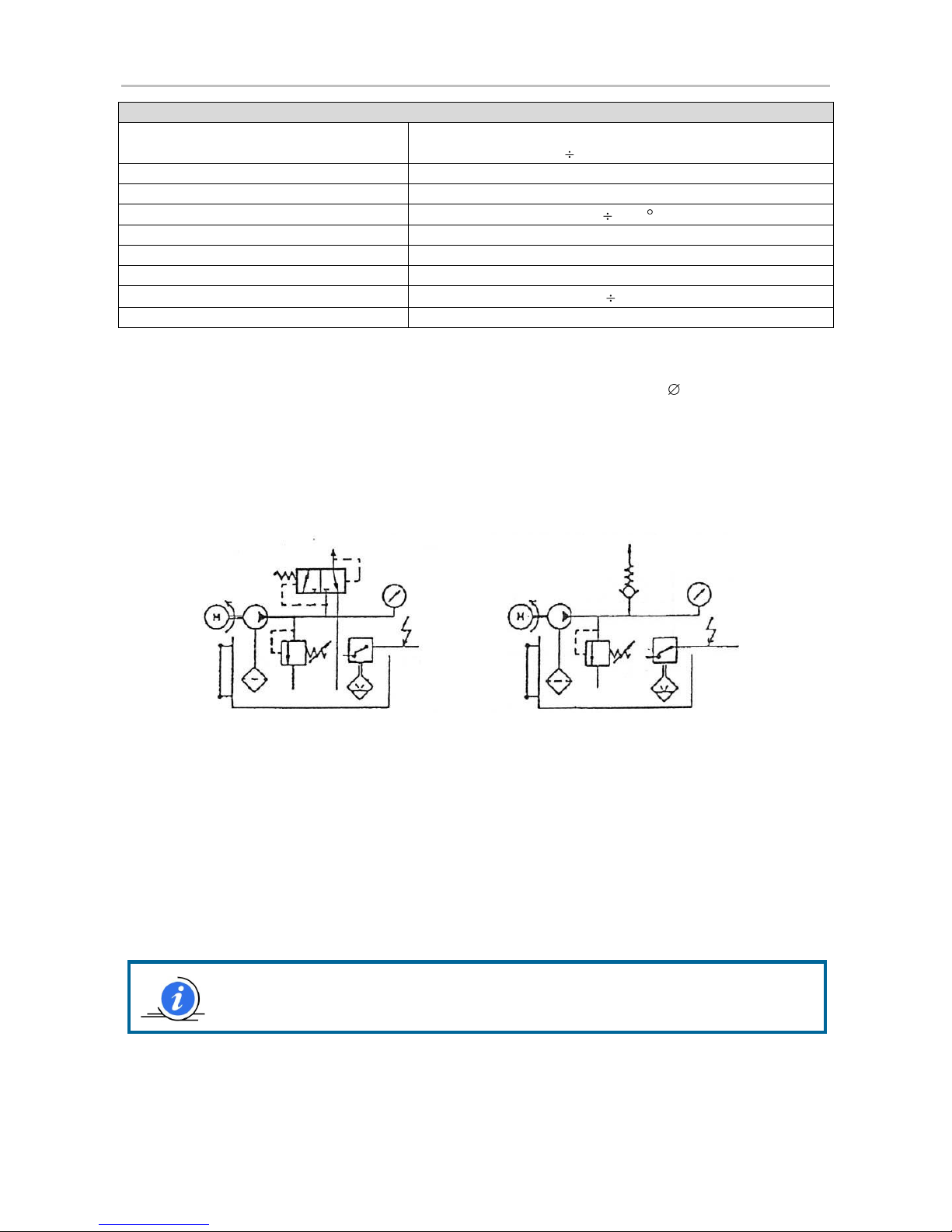
FUNCTIONAL DIAGRAM FOR SYSTEM
WITH RELEASE VALVE
FUNCTIONAL DIAGRAM FOR SYSTEM WITH NON-RETURN
VALVE
4
5. MACHINE COMPONENTS
5.1 Gear pump
Two versions available: delivery 350 cm3/min and delivey 500 cm3/min, both at 1.500 RPM.
5.2 Electric motor
Standard motor, three-phase with 4 poles multi-voltage or single-phase, as specified.
Special three-phase motor with the following voltages: 220/380 V, 240/415 V and 255/440 V, frequency 50 - 60 Hz
and power 90 W.
Single-phase motor: 220 V, 50 Hz and 90w – on request: 110 V 50/60 Hz
Size 56
IP degree of protection 55
class F insulation
Continuous running S1
24 V dc motors are available on request.
5.3 Reservoir
There are available four versions:
3 liters oil proof Transparent plastic reservoir
3 liters alluminium reservoir with visual level
6 liters oil proof Transparent plastic reservoir
6 liters painted reservoir with visual level
5.4 Indicator of minimum level
Reversible float with contact normally closed at minimum level.
Maximum commutable power 50 W 50 VA;
maximum commutable voltage 220 ac – 150 V dc, maximum current 3A;
on request, a minimum level and lubricant reserve indicator is available code 1655571.
5.5 Inductive sensor type
For oil and light grease exclusively for 3 lt tanks; minimum voltage 30 V ac and maximum voltage 250 V ac; peak
current: min. 15 mA, max. 300 mA.
5.6 Suction filter
Degree of filtration: 260 micron
5.7 Block valve
Mounted inside the tank, composed of a by-pass valve that is easily calibrated from the outside; release valve for
systems equipped with “direct response” feeding devices (04 – 06).
 Loading...