

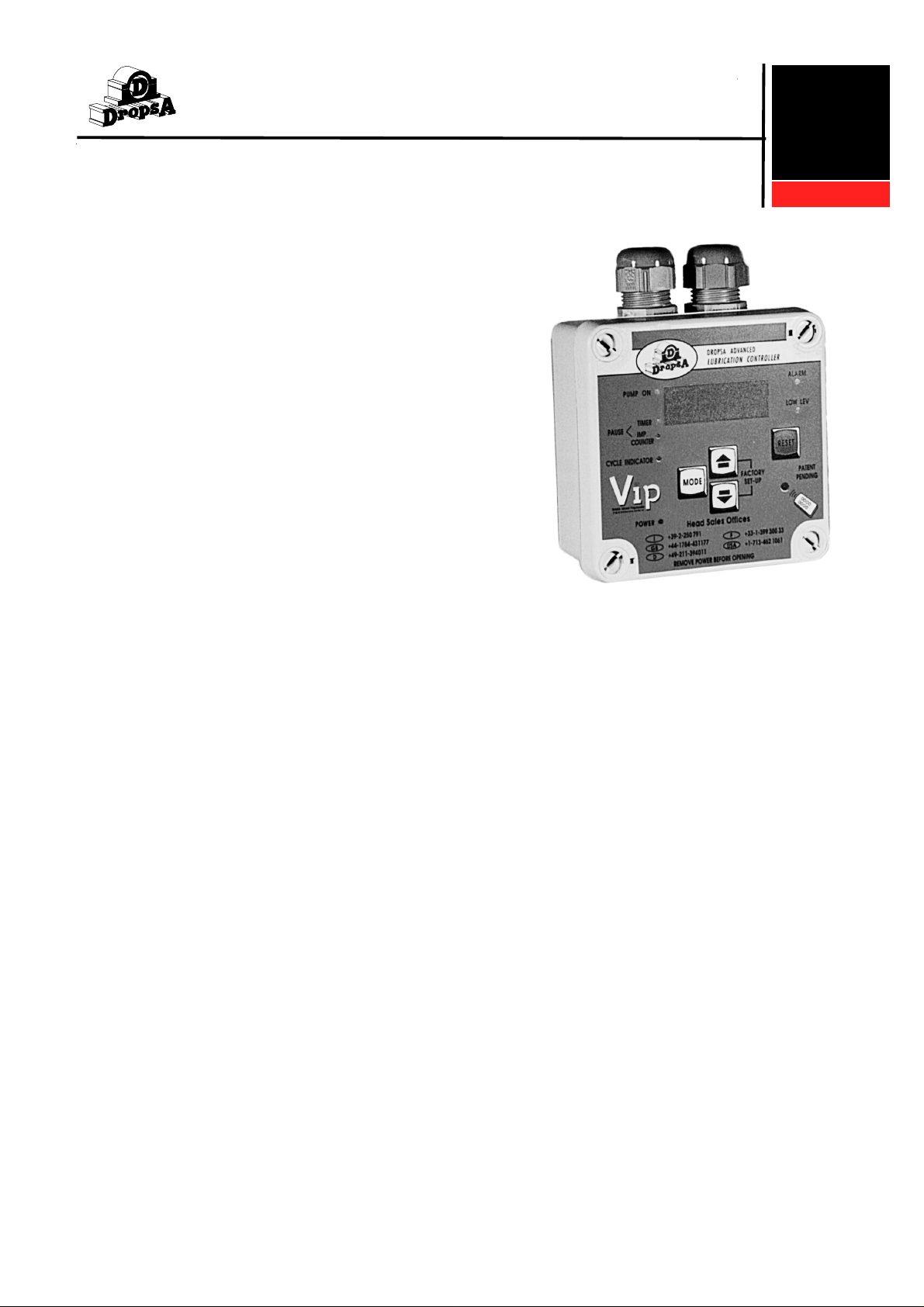
ADVANCED LUBRICATION CONTROLLER
with Quick Remote Configuration
INSTRUCTION AND PRODUCT DATA SHEET
1. DESCRIPTION:
This high performance/low cost Advanced Lubrication
Controller has been designed to control and monitor most
small to medium size lubrication systems.
The configuration parameters are all electronically stored,
in two separate menus, eliminating the need to set DIP
switches or jumpers,
The Operator Menu - is used to adjust pause and cycle
intervals.
The Factory/System Menu - is used to configure the type
of pump and lubrication system to which the controller is
connected.
In addition the controller incorporates a scanner located
under the remote control symbol on the front panel. When
used with the Transmitter Module, the configuration can
be downloaded and stored simply by positioning the module over the symbol and pressing the transmit button
This allows for a considerable time saving for OEM’s. who
use the system on a production line, eliminating the need
to individually configure each controller.
1639076
1639077
PATENT PENDING
2. SPECIFICATION:
INPUT CONTACTS:
Power:
110V/230V, 24V, 220V Single Phase
and 380V Three Phase
Power Consumption:
20 Watts.
Operating Temperature:
-5oC. to +55oC.
Control Input:
12V Max.
N.O. Pressure Switch.
Micro/Reed Switch.
Proximity (NPN/PNP Autodetection.
Oil Level:
12V Max.
Make on Low Level.
Impulse Counter:
Max. Switching Frequency;
10Hz. at 25%
OUTPUTS:
Pump/Drive Line:
110V/230V 5A 50/60Hz. or 24V
Alarm Output:
Voltage Free Contact. Max. 250V, 1A.
ENCLOSURE:
External Dimensions:
132 x 132 x 60 mm.
Fixing Dimensions:
95 x 95 mm.
Protection Grade:
IP55.
3. INSTALLATION/OPERATION:
MENU OPERATION: (Refer to table on page 2.)
ELECTRICAL CONNECTIONS AND
CIRCUIT DETAILS:
(Refer to Fig. 1.)
Note: When using the pause timer it is possible to
suspend the timer by closing contacts 14 and 15.
DIMENSIONS:
(Refer to Fig. 2.)
4. TEST PROCEDURES:
The Controller will self-diagnose on power-on and will
display any errors on the 4-digit display.
1
C1019IE-10/97
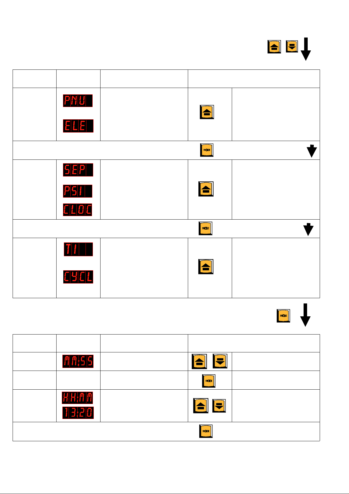
MENU OPERATION:
System Menu
The System Menu is used to configure the type of pump and
Lubrication System that is connected to the Controller
To access the System Menu press the UP and DOWN buttons together and hold for two seconds.
Parameter
Pump Type.
Press the MODE button to go to the next option.
Lubrication
System Type
Press the MODE button to go to the next option.
Pause
Interval
Selection
Screen
Display
Description Operation
The Pump receives a 4
second ON and a 4 second
OFF pulse
The Pump receives a constant
signal.
Progressive System - Monitors
switch on progressive divider.
Monitors a pressure switch on
Single Line Systems.
No monitoring, just timer.
The Pause between the Pump
ON cycle is determined by a
timer.
The Pause between Pump
cycles is determined by the
cycle switch input connected
to pulse
Press the UP button to switch
between the two options.
Press the UP button to switch
between the three options.
Press the UP button to switch
between the three options.
Operator Menu:
The Operator Menu is used to adjust the
Pump ON’ cycle and the (timer/impulse) pause interval.
To access the Operator Menu press and hold the MODE button for two seconds.
Parameters Screen
Display
Pump On
Time
Pause Timer
or
Impulse
Counter
Press the MODE button and
hold for two seconds.
2 ’VIP’ ADVANCED LUBRICATION CONTROLLER
Indicates the Minimum Pump
ON time.
Exit and go the next option. Press the MODE button and
Indicates Pause Interval.
Indicates number of impulses
between cycles.
Return to normal operating
mode
Description Operation
Use the UP and DOWN
buttons to adjust the setting.
hold for two seconds.
Use the UP and DOWN
buttons to adjust the setting.

Fig. 1. Connection Details.
Fig. 2. Fixing Details
3
Fig. 3. Panel Mounted Version.
C1019IE-10/97

trollers from the system disconnect and isolate all power
supplies.
8. OPERATING ENVIRONMENT
Controllers must not be operated in excessively corrosive
or aggressive environments. If in doubt, please contact
our Technical Office.
9. DIAGNOSTIC TABLE:
Fig. 4. Remote Transmitt Module.
5. ORDERING INFORMATION:
Part No.
1639076
1639077
1639080
1639084
1639088
1639081
1639087
Description
VIP Controller 24V Box Version.
VIP Controller 110/230V Box Version.
VIP Controller 24V Panel Mounted
Version.
VIP Controller 110/230V Panel Mounted
Version.
Remote Transmit Module.
VIP Controller 220V Single Phase in
Steel Enclosure.
VIP Controller 380V Three Phase in
Steel Enclosure.
ALARM
CODES
AO1
AO2
AO3
AO4
AO5
DESCRIPTION
OF FAULT
ACTION
No parameters set. Set parameters.
Low Level alarm. Add lubricant to the
system
The change-over
contact (in SEP
mode) has not
cycled within the
specified ’Pump
Check for loose
fittings and
blockages in
progressive system
and rectify.
ON ’ times.
PS Mode: Pressure
was already high
before the start of
Check pressure
switch and replace
if necessary.
the cycle.
PS Mode: The
system did not
achieve pressure
Check for leakage
from loose fitting
and rectify.
during the specified
cycle times.
6. SPARES
No user serviceable parts inside.
7. SAFETY REQUIREMENTS
These Controllers must be installed and operated in accordance with the requirements of this Instruction Sheet
and should not be used for any purpose than that specified
without the agreement of the suppliers.
In addition to the need to observe general safety requirements the following specific hazards apply:
Before installing or removing Advanced Lubrication Con-
ALEX/DROPSA
Vimodrone (MI)
Tel: (02) 250791
Fax: (02) 25079767
© Copyright Dropsa - all rights reserved. Reproduction of any part of this document is strictly forbidden without prior consent from Dropsa.
Dropsa reserve the right to withdraw or modify specifications without prior notice.
4 ’VIP’ ADVANCED LUBRICATION CONTROLLER
DROPSA UK LTD.
Egham, SURREY.
Tel: (01784) 431177
Fax: (01784) 438598
DROPSA GMBH
Düsseldorf, GERMANY.
Tel: (0211) 394011
Fax: (0211) 394013
DROPSA FRANCE - AME.
Garges-Les-Gonesse, CEDEX.
Tel: (01) 399.300.33
Fax: (01) 398.626.36
DROPSA CORPORATION
Houston, TEXAS.
Tel: (713) 462-1061
Fax: (713) 462-4027
 Loading...