

DROPSA 3099131, 3405000, 3406000, 3407000, 3402002 User And Maintenance Manual
...
Motor Driven Gear
User and
Maintenance Manual
Warranty Information
TABLE OF CONTENTS
1. INTRODUCTION
2. GENERAL DESCRIPTION
3. PRODUCT– MACHINE IDENTIFICATION
4. TECHNICAL SPECIFICATIONS
5. PUMP COMPONENTS
6. UNPACKING AND INSTALLING THE PUMP
7. INSTRUCTIONS FOR USE
8. TROUBLESHOOTING
9. MAINTENANCE PROCEDURE
10. DISPOSAL
11. ORDERING INFORMATION AND DIMENTIONS
12. HANDLING AND TRASPORTATION
13. OPERATING HAZARDS
14. PRECAUTIONS
15. WARRANTY INFORMATION
16. DECLARATION OF COMPLIANCE WITH STANDARDS
17. DROPSA LOCATIONS
Manual drafted in compliance with C2010IE – WK 20/11
EC Directive 06/42
http://www.dropsa.com
Pumps

2
1. INTRODUCTION
This user’s and maintenance manual refers to motor-driven gear pumps 37000-3400000, 3410-
It is recommended that this manual is carefully kept in good condition and is always available to persons requiring to consult it.
To request further copies, updates or clarifications with respect to this manual contact the Engineering Department at Dropsa
SpA.
The use of the pump referred to in this manual must be entrusted to qualified personnel with a knowledge of hydraulics and
electrical systems.
The manufacturer reserves the right to update the product and/or the user’s manual without the obligation to revise previous
versions. It is however, possible to contact the Engineering Department for the latest revision in use. You can find additional
copies and newer revisions of this document from our website http://www.dropsa.com. Alternatively contact one of our sales
offices.
The pump, and any accessories mounted on it, should be carefully checked immediately on receipt and in the event of any
discrepancy or complaint the Dropsa SpA Sales Department should be contacted without delay.
DROPSA S.p.A. declines to accept any responsibility for injuries to persons or damage to property in the event of the nonobservance of the information presented in this manual.
Any modification to component parts of the system or the different destination of use of this system or its parts without prior
written authorisation from DROPSA S.p.A. will absolve the latter from any responsibility for injury or damage to persons and/or
property and will release them from all obligations arising from the guarantee.
Instructions for the correct ordering of the required model, and a list of importers, is shown in Section 4.
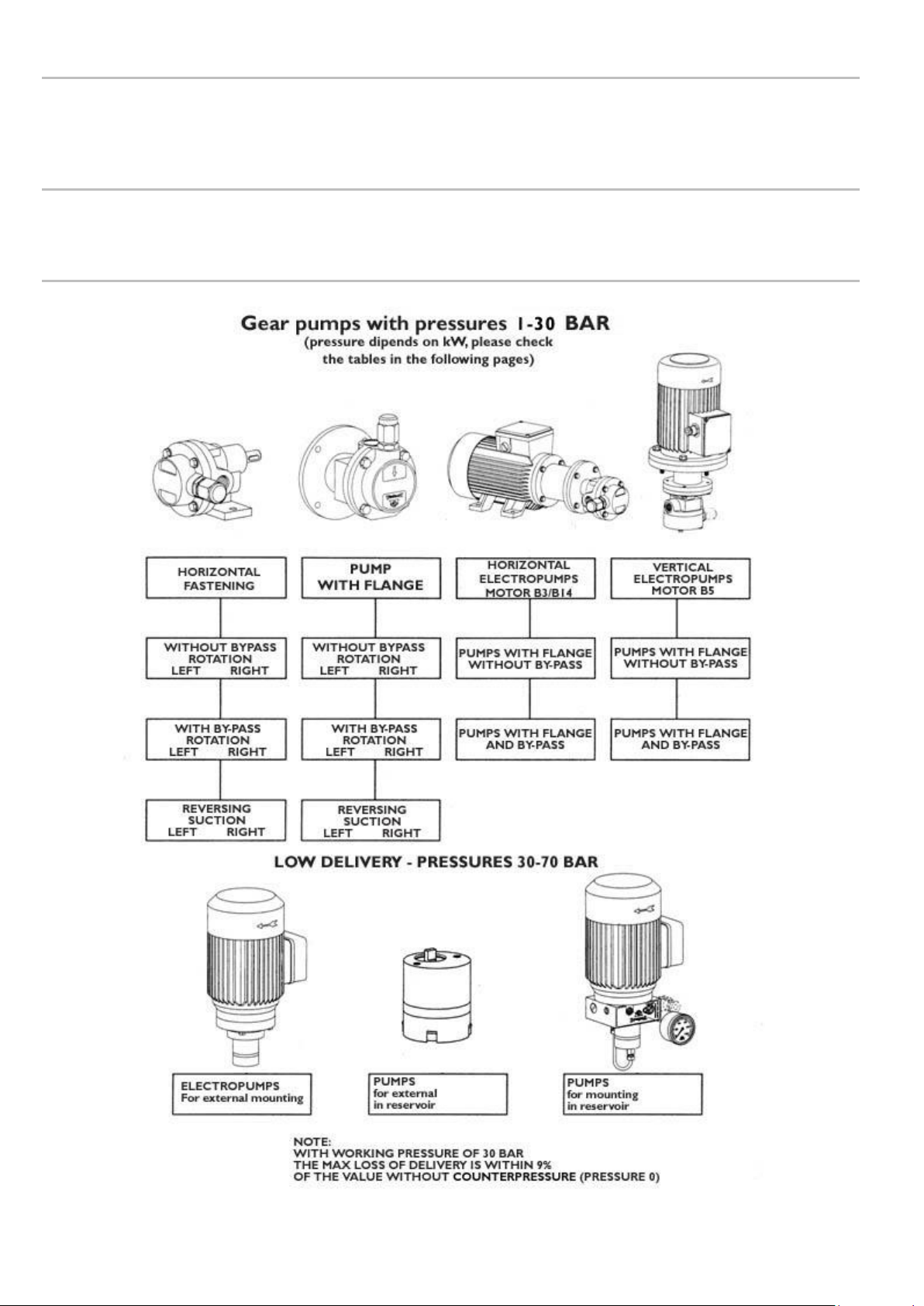
2. GENERAL DESCRIPTION
These new pump units have been designed as the result of over thirty years experience in the field of developing and
manufacturing gear pumps.
The application possibilities are numerous; the pumps are self-lubricating and are able to operate with oils or any other fluid
with proven lubricating capacity.
These pumps can therefore be utilised in the fields of lubrication, refrigeration, hydraulics and, more generally, for the
circulation of fluids for machines, motors and linear motion applications; these units can also be employed on recirculating
systems without the need for particularly fine filtering of the circulation fluid.
One of the most striking features of these pumps is the high degree of silentness in operation, obtained with the use of gears
specially designed for this type of unit.
Also, thanks to particularly precise machining and finishing, a significant improvement has been achieved in efficiencies
compared to all previous similar models produced.
To ensure an external seal the pumps have an “O” ring located between the pump body and the relative cover in addition to a
lip seal on the main shaft.
The body of the pump is produced in hydraulic cast iron and the gears and relative shafts in chrome-nickel steel – carburized,
hardened and ground.
The body of the low flow rate pump (up to 500 cc/min) is made of sintered steel; the shafts and gears in carburized and
hardened steel with a seal on the main shaft.
WARNING
For all the motor-driven pumps we have shown the applied power to the motors in function of the maximum pressure demand
indicated in the table. For higher pressures the motor must be suitably sized; accordingly, to obtain a quotation, state the
voltage, the maximum operating pressure and if the service will be continuous or intermittent. (Max pressure = 30 bar for
continuous service); (max. pressure = 60 bar for intermittent service); (For cylinder block versions from 1-30 bar it depends form
delivery and kW). Working temperature of the fluid –20 - +100 degrees with low to medium velocity oil.
On request flameproof motors can be supplied in various voltages.
Request availability from Dropsa SpA.
3
3. PRODUCT – MACHINE IDENTIFICATION
Pump identification label is located on the front side of the grease operating pump and contains pump serial number and details
of its operating parameters.
4. TECHNICAL SPECIFICATION
See chapter 11 “ORDERING INFORMATION”
5. PUMP COMPONENTS
4
6. UNPACKING AND INSTALLING THE PUMP
6.1 UNPACKING
Once a suitable location has been found to install the unit remove the pump from the packaging. Check the pump has not been
damaged during transportation or storage. No particular disposal procedures are necessary, however packing should be
disposed of in accordance with regulations that may be in force in your area or state.
6.2 INSTALLING THE PUMP
Allow sufficient space for the installation, leaving minimum 100 mm (3.9 in.) around the unit.
In order to avoid unnatural posture for personnel install the machine in a comfortable and easy-to-reach location.
Do not install the unit in aggressive/explosive/inflammable environments or on vibrating surfaces.
WARNING: At the end of all the connecting operations, make sure that pipes and wires are safe from impacts and carefully
fixed.
7. INSTRUCTIONS FOR USE
After fixing the pump at its support, fill the tank with pure oil.
Operate the pump until the oil comes out without air bubbles.
Attach the tubing to the pump taking care of blowing compressed air inside to remove any dirt.
Reactivate the pump until oil comes out from the pipes regularly and without bubbles.
Attach piping to the lubrication points
Always pay attention to the direction of rotation.
In case of direct connection, run the engine for a few seconds checking the direction of rotation, if it is wrong to
switch two power phases.
The pump must not work with the wrong direction of rotation.
In the event of a complete unit, pump with electric motor on support, they must be carefully balanced in both
directions, to ensure that whole function silently.
5
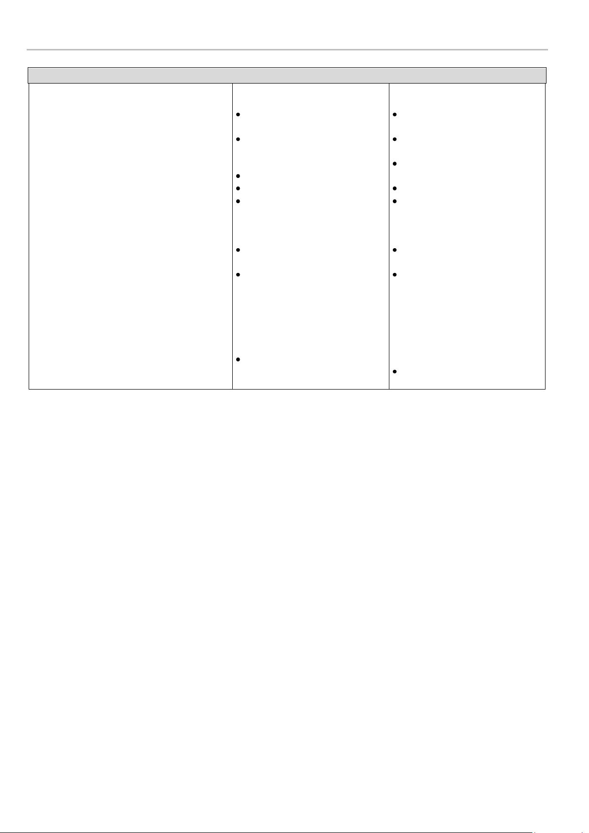
8. TROUBLESHOOTING
DIAGNOSTIC TABLE
INDICATION
The pump does not deliver oil or does not
deliver oil in the exact quantity prescribed
The pump does not deliver oil at the prescribed
pressure
PROBABLE CAUSE
Drawing in air due to the tank
being empty
The splash filter is dirty or
blocked
The connections are loose
Pump has deteriorated
Pressure regulating valve loose,
so the oil returns immediately to
the tank before flowing through
the delivery valve
Release valve damaged
Incorrect setting of the
regulating valve
Presence of dirt under the by-
pass valve
REMEDY
Refill the tank and purge air
from the system
Wash the filter and blow it
through with compressed air
Set all connections ensuring
there are no leakages
Replace the pump
Set the regulating screw until oil
exits from the delivery
Replace the valve
To the pump outlet connect a
tube approximately 30cm long
with a manometer connected to
the free end. Regulate the valve
by means of turning the screw
and reading the corresponding
pressure value on the
manometer
Disassemble the valve and clean
or replace it as necessary
 Loading...